WO2015075767A1 - 投射型映像表示装置 - Google Patents
投射型映像表示装置 Download PDFInfo
- Publication number
- WO2015075767A1 WO2015075767A1 PCT/JP2013/081131 JP2013081131W WO2015075767A1 WO 2015075767 A1 WO2015075767 A1 WO 2015075767A1 JP 2013081131 W JP2013081131 W JP 2013081131W WO 2015075767 A1 WO2015075767 A1 WO 2015075767A1
- Authority
- WO
- WIPO (PCT)
- Prior art keywords
- projection
- display
- video
- finger
- image
- Prior art date
- Legal status (The legal status is an assumption and is not a legal conclusion. Google has not performed a legal analysis and makes no representation as to the accuracy of the status listed.)
- Ceased
Links
Images
























Classifications
-
- G—PHYSICS
- G06—COMPUTING OR CALCULATING; COUNTING
- G06F—ELECTRIC DIGITAL DATA PROCESSING
- G06F3/00—Input arrangements for transferring data to be processed into a form capable of being handled by the computer; Output arrangements for transferring data from processing unit to output unit, e.g. interface arrangements
- G06F3/01—Input arrangements or combined input and output arrangements for interaction between user and computer
- G06F3/03—Arrangements for converting the position or the displacement of a member into a coded form
- G06F3/041—Digitisers, e.g. for touch screens or touch pads, characterised by the transducing means
- G06F3/042—Digitisers, e.g. for touch screens or touch pads, characterised by the transducing means by opto-electronic means
- G06F3/0425—Digitisers, e.g. for touch screens or touch pads, characterised by the transducing means by opto-electronic means using a single imaging device like a video camera for tracking the absolute position of a single or a plurality of objects with respect to an imaged reference surface, e.g. video camera imaging a display or a projection screen, a table or a wall surface, on which a computer generated image is displayed or projected
-
- G—PHYSICS
- G06—COMPUTING OR CALCULATING; COUNTING
- G06F—ELECTRIC DIGITAL DATA PROCESSING
- G06F3/00—Input arrangements for transferring data to be processed into a form capable of being handled by the computer; Output arrangements for transferring data from processing unit to output unit, e.g. interface arrangements
- G06F3/01—Input arrangements or combined input and output arrangements for interaction between user and computer
- G06F3/017—Gesture based interaction, e.g. based on a set of recognized hand gestures
-
- G—PHYSICS
- G06—COMPUTING OR CALCULATING; COUNTING
- G06F—ELECTRIC DIGITAL DATA PROCESSING
- G06F3/00—Input arrangements for transferring data to be processed into a form capable of being handled by the computer; Output arrangements for transferring data from processing unit to output unit, e.g. interface arrangements
- G06F3/01—Input arrangements or combined input and output arrangements for interaction between user and computer
- G06F3/03—Arrangements for converting the position or the displacement of a member into a coded form
- G06F3/033—Pointing devices displaced or positioned by the user, e.g. mice, trackballs, pens or joysticks; Accessories therefor
- G06F3/0346—Pointing devices displaced or positioned by the user, e.g. mice, trackballs, pens or joysticks; Accessories therefor with detection of the device orientation or free movement in a three-dimensional [3D] space, e.g. 3D mice, 6-DOF [six degrees of freedom] pointers using gyroscopes, accelerometers or tilt-sensors
-
- G—PHYSICS
- G06—COMPUTING OR CALCULATING; COUNTING
- G06F—ELECTRIC DIGITAL DATA PROCESSING
- G06F3/00—Input arrangements for transferring data to be processed into a form capable of being handled by the computer; Output arrangements for transferring data from processing unit to output unit, e.g. interface arrangements
- G06F3/01—Input arrangements or combined input and output arrangements for interaction between user and computer
- G06F3/03—Arrangements for converting the position or the displacement of a member into a coded form
- G06F3/041—Digitisers, e.g. for touch screens or touch pads, characterised by the transducing means
- G06F3/042—Digitisers, e.g. for touch screens or touch pads, characterised by the transducing means by opto-electronic means
- G06F3/0425—Digitisers, e.g. for touch screens or touch pads, characterised by the transducing means by opto-electronic means using a single imaging device like a video camera for tracking the absolute position of a single or a plurality of objects with respect to an imaged reference surface, e.g. video camera imaging a display or a projection screen, a table or a wall surface, on which a computer generated image is displayed or projected
- G06F3/0426—Digitisers, e.g. for touch screens or touch pads, characterised by the transducing means by opto-electronic means using a single imaging device like a video camera for tracking the absolute position of a single or a plurality of objects with respect to an imaged reference surface, e.g. video camera imaging a display or a projection screen, a table or a wall surface, on which a computer generated image is displayed or projected tracking fingers with respect to a virtual keyboard projected or printed on the surface
-
- G—PHYSICS
- G06—COMPUTING OR CALCULATING; COUNTING
- G06F—ELECTRIC DIGITAL DATA PROCESSING
- G06F3/00—Input arrangements for transferring data to be processed into a form capable of being handled by the computer; Output arrangements for transferring data from processing unit to output unit, e.g. interface arrangements
- G06F3/01—Input arrangements or combined input and output arrangements for interaction between user and computer
- G06F3/048—Interaction techniques based on graphical user interfaces [GUI]
-
- G—PHYSICS
- G06—COMPUTING OR CALCULATING; COUNTING
- G06F—ELECTRIC DIGITAL DATA PROCESSING
- G06F3/00—Input arrangements for transferring data to be processed into a form capable of being handled by the computer; Output arrangements for transferring data from processing unit to output unit, e.g. interface arrangements
- G06F3/01—Input arrangements or combined input and output arrangements for interaction between user and computer
- G06F3/048—Interaction techniques based on graphical user interfaces [GUI]
- G06F3/0484—Interaction techniques based on graphical user interfaces [GUI] for the control of specific functions or operations, e.g. selecting or manipulating an object, an image or a displayed text element, setting a parameter value or selecting a range
- G06F3/04845—Interaction techniques based on graphical user interfaces [GUI] for the control of specific functions or operations, e.g. selecting or manipulating an object, an image or a displayed text element, setting a parameter value or selecting a range for image manipulation, e.g. dragging, rotation, expansion or change of colour
-
- G—PHYSICS
- G06—COMPUTING OR CALCULATING; COUNTING
- G06F—ELECTRIC DIGITAL DATA PROCESSING
- G06F3/00—Input arrangements for transferring data to be processed into a form capable of being handled by the computer; Output arrangements for transferring data from processing unit to output unit, e.g. interface arrangements
- G06F3/01—Input arrangements or combined input and output arrangements for interaction between user and computer
- G06F3/048—Interaction techniques based on graphical user interfaces [GUI]
- G06F3/0487—Interaction techniques based on graphical user interfaces [GUI] using specific features provided by the input device, e.g. functions controlled by the rotation of a mouse with dual sensing arrangements, or of the nature of the input device, e.g. tap gestures based on pressure sensed by a digitiser
- G06F3/0488—Interaction techniques based on graphical user interfaces [GUI] using specific features provided by the input device, e.g. functions controlled by the rotation of a mouse with dual sensing arrangements, or of the nature of the input device, e.g. tap gestures based on pressure sensed by a digitiser using a touch-screen or digitiser, e.g. input of commands through traced gestures
-
- G—PHYSICS
- G06—COMPUTING OR CALCULATING; COUNTING
- G06F—ELECTRIC DIGITAL DATA PROCESSING
- G06F3/00—Input arrangements for transferring data to be processed into a form capable of being handled by the computer; Output arrangements for transferring data from processing unit to output unit, e.g. interface arrangements
- G06F3/01—Input arrangements or combined input and output arrangements for interaction between user and computer
- G06F3/048—Interaction techniques based on graphical user interfaces [GUI]
- G06F3/0487—Interaction techniques based on graphical user interfaces [GUI] using specific features provided by the input device, e.g. functions controlled by the rotation of a mouse with dual sensing arrangements, or of the nature of the input device, e.g. tap gestures based on pressure sensed by a digitiser
- G06F3/0488—Interaction techniques based on graphical user interfaces [GUI] using specific features provided by the input device, e.g. functions controlled by the rotation of a mouse with dual sensing arrangements, or of the nature of the input device, e.g. tap gestures based on pressure sensed by a digitiser using a touch-screen or digitiser, e.g. input of commands through traced gestures
- G06F3/04883—Interaction techniques based on graphical user interfaces [GUI] using specific features provided by the input device, e.g. functions controlled by the rotation of a mouse with dual sensing arrangements, or of the nature of the input device, e.g. tap gestures based on pressure sensed by a digitiser using a touch-screen or digitiser, e.g. input of commands through traced gestures for inputting data by handwriting, e.g. gesture or text
-
- G—PHYSICS
- G09—EDUCATION; CRYPTOGRAPHY; DISPLAY; ADVERTISING; SEALS
- G09G—ARRANGEMENTS OR CIRCUITS FOR CONTROL OF INDICATING DEVICES USING STATIC MEANS TO PRESENT VARIABLE INFORMATION
- G09G5/00—Control arrangements or circuits for visual indicators common to cathode-ray tube indicators and other visual indicators
-
- G—PHYSICS
- G09—EDUCATION; CRYPTOGRAPHY; DISPLAY; ADVERTISING; SEALS
- G09G—ARRANGEMENTS OR CIRCUITS FOR CONTROL OF INDICATING DEVICES USING STATIC MEANS TO PRESENT VARIABLE INFORMATION
- G09G5/00—Control arrangements or circuits for visual indicators common to cathode-ray tube indicators and other visual indicators
- G09G5/36—Control arrangements or circuits for visual indicators common to cathode-ray tube indicators and other visual indicators characterised by the display of a graphic pattern, e.g. using an all-points-addressable [APA] memory
-
- H—ELECTRICITY
- H04—ELECTRIC COMMUNICATION TECHNIQUE
- H04N—PICTORIAL COMMUNICATION, e.g. TELEVISION
- H04N5/00—Details of television systems
- H04N5/74—Projection arrangements for image reproduction, e.g. using eidophor
-
- H—ELECTRICITY
- H04—ELECTRIC COMMUNICATION TECHNIQUE
- H04N—PICTORIAL COMMUNICATION, e.g. TELEVISION
- H04N9/00—Details of colour television systems
- H04N9/12—Picture reproducers
- H04N9/31—Projection devices for colour picture display, e.g. using electronic spatial light modulators [ESLM]
-
- H—ELECTRICITY
- H04—ELECTRIC COMMUNICATION TECHNIQUE
- H04N—PICTORIAL COMMUNICATION, e.g. TELEVISION
- H04N9/00—Details of colour television systems
- H04N9/12—Picture reproducers
- H04N9/31—Projection devices for colour picture display, e.g. using electronic spatial light modulators [ESLM]
- H04N9/3179—Video signal processing therefor
- H04N9/3185—Geometric adjustment, e.g. keystone or convergence
-
- H—ELECTRICITY
- H04—ELECTRIC COMMUNICATION TECHNIQUE
- H04N—PICTORIAL COMMUNICATION, e.g. TELEVISION
- H04N9/00—Details of colour television systems
- H04N9/12—Picture reproducers
- H04N9/31—Projection devices for colour picture display, e.g. using electronic spatial light modulators [ESLM]
- H04N9/3191—Testing thereof
- H04N9/3194—Testing thereof including sensor feedback
-
- G—PHYSICS
- G06—COMPUTING OR CALCULATING; COUNTING
- G06F—ELECTRIC DIGITAL DATA PROCESSING
- G06F2203/00—Indexing scheme relating to G06F3/00 - G06F3/048
- G06F2203/041—Indexing scheme relating to G06F3/041 - G06F3/045
- G06F2203/04101—2.5D-digitiser, i.e. digitiser detecting the X/Y position of the input means, finger or stylus, also when it does not touch, but is proximate to the digitiser's interaction surface and also measures the distance of the input means within a short range in the Z direction, possibly with a separate measurement setup
-
- G—PHYSICS
- G06—COMPUTING OR CALCULATING; COUNTING
- G06F—ELECTRIC DIGITAL DATA PROCESSING
- G06F2203/00—Indexing scheme relating to G06F3/00 - G06F3/048
- G06F2203/048—Indexing scheme relating to G06F3/048
- G06F2203/04808—Several contacts: gestures triggering a specific function, e.g. scrolling, zooming, right-click, when the user establishes several contacts with the surface simultaneously; e.g. using several fingers or a combination of fingers and pen
-
- G—PHYSICS
- G06—COMPUTING OR CALCULATING; COUNTING
- G06F—ELECTRIC DIGITAL DATA PROCESSING
- G06F3/00—Input arrangements for transferring data to be processed into a form capable of being handled by the computer; Output arrangements for transferring data from processing unit to output unit, e.g. interface arrangements
- G06F3/01—Input arrangements or combined input and output arrangements for interaction between user and computer
- G06F3/048—Interaction techniques based on graphical user interfaces [GUI]
- G06F3/0487—Interaction techniques based on graphical user interfaces [GUI] using specific features provided by the input device, e.g. functions controlled by the rotation of a mouse with dual sensing arrangements, or of the nature of the input device, e.g. tap gestures based on pressure sensed by a digitiser
- G06F3/0488—Interaction techniques based on graphical user interfaces [GUI] using specific features provided by the input device, e.g. functions controlled by the rotation of a mouse with dual sensing arrangements, or of the nature of the input device, e.g. tap gestures based on pressure sensed by a digitiser using a touch-screen or digitiser, e.g. input of commands through traced gestures
- G06F3/04886—Interaction techniques based on graphical user interfaces [GUI] using specific features provided by the input device, e.g. functions controlled by the rotation of a mouse with dual sensing arrangements, or of the nature of the input device, e.g. tap gestures based on pressure sensed by a digitiser using a touch-screen or digitiser, e.g. input of commands through traced gestures by partitioning the display area of the touch-screen or the surface of the digitising tablet into independently controllable areas, e.g. virtual keyboards or menus
Definitions
- the present invention relates to a projection type video display device that projects an image.
- a technology has been devised for controlling the display orientation to be easy for the user to see when the projection display device projects an image on a horizontal surface such as a desk.
- a projection display device installed above a projectile includes an imaging unit, obtains a user interface image that captures an operator's motion, and controls a display screen based on the result of motion detection. Says.
- Patent Document 2 describes a method in which a display device installed above a projectile recognizes the position and operation of the user, the shape of the projectile, and controls the display position, display orientation, and the like accordingly.
- Patent Documents 1 and 2 are intended to display an image on a projectile that can be easily moved, such as a desk, from a display device installed above the projectile, and the display device according to the movement of the projectile There are issues with ease of use, such as the need for movement.
- the point to be photographed for performing movement recognition is far from the imaging unit of the display device installed above, and the point to be photographed is one of the body of the user.
- the accuracy of recognition due to the fact that it is difficult to take a picture because it is shielded by the part.
- the present invention is a projection-type image display device, wherein the projection image is projected onto a surface that is at least partially overlapped with an image projection unit that projects an image, and an image projection surface that the image projection unit projects. And at least one illumination unit that emits illumination light different from the above, an imaging unit that captures an image using reflected light of the illumination light, and an operator's finger touching the video projection surface based on an image captured by the imaging unit And a display control unit configured to control to change at least one partial video included in the video projected by the video projection unit based on a detection result by the detection unit.
- the projection type image display device is characterized in that it is installed on a surface of the image projection surface and projects the image.
- the figure explaining the determination of the approach degree by a feature point The figure explaining determination of the contact point by a feature point.
- the figure which shows the processing flow of the operation detection method The figure which shows the processing flow of the operation detection method.
- the figure which shows an example of the control according to the pointing direction The figure which shows that a user exists close to a rectangular desk.
- the figure which shows an example of the parallel movement by finger operation The figure which shows an example of the parallel movement by finger operation.
- the figure which shows an example of the rotational movement by finger operation The figure which shows an example of the rotational movement by finger operation.
- the figure which shows an example of operation which increases the number of display screens by finger operation The figure which shows an example of operation which increases the number of display screens by finger operation.
- the figure which shows an example of operation which expands the display screen by finger operation The figure which shows an example of operation which expands the display screen by finger operation.
- the figure which shows an example of multiple finger operation The figure which shows an example of multiple finger operation.
- the figure which shows an example of multiple finger operation The figure which shows an example of multiple finger operation.
- the figure which shows an example of multiple finger operation The figure which shows an example of multiple finger operation.
- the figure which shows an example of multiple finger operation The figure which shows an example of multiple finger operation.
- the figure which shows an example of multiple finger operation The figure which shows an example of multiple finger operation.
- the figure which shows an example of multiple finger operation The figure which shows an example of multiple finger operation.
- the figure which shows an example of menu or detailed information display operation. The figure which shows an example of menu or detailed information display operation.
- the figure which shows an example of menu or detailed information display operation The figure which shows an example of menu or detailed information display operation.
- the figure which shows an example of menu or detailed information display operation The figure which shows an example of menu or detailed information display operation.
- the figure which shows an example of menu or detailed information display operation The figure which shows an example of menu or detailed information display operation.
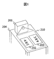
- FIG. 1 shows an example in which two images 202 and 203 with different rotation angles are projected onto a desk with a projection display device 201 installed on a desk, for a plurality of users who see different directions.
- video projection onto a “desk” is described as an example, but the “desk” is an example of a video projection surface. Therefore, the present embodiment may target other video projection surfaces (may be other structures and floors).
- the maximum range 210 in which the projection display device 205 can optically project an image is indicated by a broken line.
- the maximum projection range 210 may also be shown in the following drawings.
- the projection display device 205 projects two display screens 202 and 203 as an example. Display screens 202 and 203 correspond to OSD (on-screen display) screens to be described later. That is, the images displayed on the display screens 202 and 203 are partial images within the maximum projection range 210.
- a method of displaying the design drawing of the apparatus over the entire maximum projection range 210 and displaying the explanatory drawing of the design drawing on the display screens 202 and 203 can be considered.
- FIG. 2 shows an example of a configuration diagram of the projection display device 205 with an operation detection function in which the user controls the display screen by gesture input in such a case.
- the projection display device 205 with an operation detection function includes a camera 100, two illuminations 101 and 102, a shadow area extraction unit 104, a feature point detection unit 105, an approach degree detection unit 106, a contact point detection unit 107, a contour detection unit 108, A direction detection unit 109, a control unit 110, a display control unit 111, a drive circuit unit 112, an input terminal unit 113, an input signal processing unit 114, and a projection unit 115 are included.
- the control unit 110 generates detection result data of operation states such as the degree of finger approach to the operation surface detected by each detection unit, the contact point coordinates, and the pointing direction.
- the display control unit 111 generates display control data such as an operation mode, a pointer display position, and a pointer display direction based on the detection result, and performs display control on a video signal that passes through the input terminal 113 and the input signal processing unit 114. Perform processing based on the data.
- the processed video signal is processed by the drive circuit unit 112 for projection, and is projected from the projection unit 115 onto the projection.
- description of buffers, memories, and the like is omitted, but necessary buffers, memories, and the like may be mounted as appropriate.
- FIG. 3 is a diagram illustrating an example of a state in which the user 3 performs an operation on the display screen 203 of the projection display device 205 with an operation detection function.
- the user 3 performs a desired operation by bringing the finger 30, which is an operation unit, close to the display screen 203 of the projectile 204 and contacting a certain position. That is, for example, the display screen 203 of the projection 204 that is a desk surface is also an operation surface for the user 3 to operate the projection display device 205.
- the operation by the user 3 will be described in detail later.
- the projection display device 205 with an operation detection function includes two lights 101 and 102 and a camera 100.
- the two lights 101 and 102 irradiate the finger 30 of the user 3, and the camera 100 images the finger 30 and the vicinity thereof. Since the shadow shape of the finger 30 changes when the finger 30 approaches or comes into contact with the projectile 204, the projection display device 205 analyzes the image of the camera 100 and detects the degree of finger approach, the contact point, and the pointing direction. .
- the projection display device 205 with the operation detection function when the illuminations 101 and 102 irradiate the finger 30, the chance of light being shielded can be reduced.
- the camera 100 includes an image sensor, a lens, and the like, and captures an image including the finger 30 that is an operation unit of the user 3.
- the two illuminations 101 and 102 are composed of a light emitting diode, a circuit board, a lens, and the like.
- the projection light 204 and the finger 30 of the user 3 are irradiated with illumination light, and the shadow of the finger 30 appears in the image captured by the camera 100. Project.
- the illuminations 101 and 102 may be infrared illumination, and the camera 100 may be an infrared camera.
- the infrared light image captured by the camera 100 can be obtained separately from the visible light image that is the image of the image signal projected from the projection display device 205 with an operation detection function.
- the illumination light / imaging light may be any light outside visible light that can be separated from the projected image of the projection display device 205, and therefore, ultraviolet light may be used instead of infrared light.
- the shadow area extraction unit 104 extracts a shadow area from an image obtained by the camera 100 and generates a shadow image.
- the difference image is generated by subtracting the background image of the projectile 204 captured in advance from the captured image at the time of detecting the operation, the luminance of the difference image is binarized with a predetermined threshold Lth, and the area below the threshold is a shadow area What should I do?
- a so-called labeling process is performed in which shadow areas that are not connected to each other are distinguished from each other as different shadows. By the labeling process, it is possible to identify which finger corresponds to the extracted plurality of shadows, that is, two pairs of shadows corresponding to one finger.
- the feature point detection unit 105 detects a specific position (hereinafter referred to as a feature point) in the shadow image extracted by the shadow region extraction unit 104.
- a feature point a specific position (hereinafter referred to as a feature point) in the shadow image extracted by the shadow region extraction unit 104.
- the tip position corresponding to the fingertip position
- Various methods are used for feature point detection.
- the tip position it can be detected from the coordinate data of the pixels that make up the shadow image, or a part that matches the specific shape of the feature point is imaged. It can also be detected by recognition or the like. Since one feature point is detected from one shadow, two points are detected for one finger (two shadows).
- the proximity detection unit 106 measures a distance d between two feature points detected by the feature point detection unit 105, and detects a gap s (approach A) between the finger and the operation surface based on the distance d. Thereby, it is determined whether the finger is in contact with the operation surface or not.
- the contact point detection unit 107 detects the contact point of the finger with respect to the operation surface based on the position of the feature point, and determines the coordinates. calculate.
- the contour detection unit 108 extracts the contour of the shadow region from the shadow image extracted by the shadow region extraction unit 104.
- the contour image can be obtained by scanning the shadow image in a certain direction to determine the start pixel of the contour tracking, and tracking the neighboring pixels of the start pixel counterclockwise.
- the direction detection unit 109 extracts a substantially straight line segment from the contour line detected by the contour detection unit 108. Then, the pointing direction of the finger on the operation surface is detected based on the extracted direction of the contour line.
- each detection unit described above is not limited to the above method, and other image processing algorithms may be used.
- Each detection unit described above can be configured not only by hardware based on a circuit board but also by software.
- the control unit 110 controls the operation of the entire apparatus, and generates detection result data such as the degree of finger approach to the operation surface detected by each detection unit, contact point coordinates, and pointing direction.
- the display control unit 111 generates display control data such as an operation mode, a pointer position, and a pointer direction based on the detection result data such as the finger approach degree, the contact point coordinates, and the pointing direction generated by the control unit 110 and inputs them. Processing based on the display control data is performed on the video signal that passes through the terminal 113 and the input signal processing unit 114.
- the drive circuit unit 112 performs processing for projecting the processed video signal as a display video.
- the display image is projected from the projection unit 115 to the projectile.
- Each unit so far has been described as an example provided in one projection display device 205 with an operation detection function. However, a part of these units may be configured as separate units and connected by transmission lines. Absent.
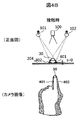
- FIG. 4A and FIG. 4B are diagrams showing the shape of the shadow of the user's finger generated by the two illuminations.
- 4A shows a state where the finger 30 and the projectile 204 are not in contact
- FIG. 4B shows a state where they are in contact.
- the finger 30 when the finger 30 is not in contact with the projectile 204 (gap s), the light from the two illuminations 101 and 102 is blocked by the finger 30, and shadows 401 and 402 (shown by diagonal lines), respectively. Is formed. In the camera image, the two shadows 401 and 402 exist on both sides of the finger 30 apart from each other.
- the two shadows 401 and 402 are close to each other at the position of the fingertip of the finger 30. .
- a partial area of the shadows 401 and 402 is hidden behind the finger 30, but this hidden part is not included in the shadow area.
- the contact between the finger 30 and the operation surface 204 is determined using the property that the shadow 401 and the shadow 402 are close to each other (especially the distance between the feature points). .
- FIG. 5 is a diagram showing the influence of the shape of the shadow depending on the operation position of the user.
- the camera images when the user's operation position is shifted from the center of the projection 204 to the left (user position 3) and when the user's operation position is shifted to the right (user position 3 ') are compared.
- the positional relationship of the shadows 401 (401 ') and 402 (402') with respect to the finger 30 (30 ') does not change in those camera images. That is, the shadows 401 (401 ') and 402 (402') always exist on both sides of the finger 30 (30 ') regardless of the user operation position.
- FIG. 6 is a diagram showing the relationship between the gap between the finger and the operation surface and the shape of the shadow.
- the distance between the two shadows 401 and 402 formed on both sides of the finger 30 varies depending on the gap s between the finger 30 and the projectile 204.
- feature points 601 and 602 are set inside the respective shadows 401 and 402, and the distance d between the feature points is measured.
- a feature point is set at the tip position (fingertip position) of the shadow.
- the distance d between the feature points 601 and 602 is the minimum value. It becomes.
- FIG. 7 is a diagram for explaining the approach degree determination in the approach degree detection unit 106.
- the finger approach degree A is determined based on the distance d between the feature points.
- four threshold values d1, d2, d3, d4 (where d1 ⁇ d2 ⁇ d3 ⁇ d4) are determined for the distance d between feature points. Accordingly, the degree of approach A is classified into five levels (levels 1 to 5), and the larger the level value, the smaller the gap s between the finger 30 and the projectile 204.
- the proximity A is classified into four levels (levels 4 to 1) using threshold values d2 to d4.
- the degree of approach A is determined to be the minimum level 1.
- the degree of approach is classified into five stages using four thresholds, but the number of degrees of approach is not limited to this, and may be set as appropriate according to the control content.
- FIG. 8 is a diagram for explaining the determination of the contact point in the contact point detection unit 107.
- the shapes of the shadows 401 and 402 when the finger 30 is in contact with the projectile 204 are shown.
- the feature points 601 and 602 are set at the tip positions of the shadows 401 and 402, respectively.
- the midpoint P of the two feature points 601 and 602 is regarded as a contact point between the finger 30 and the projectile 204, and its coordinates Can be calculated.
- the feature points 601 and 602 are set at the tip positions of the respective shadows 401 and 402.
- setting of the feature points is easy and the position of the contact point P is also set. Since it exists in the vicinity, it can be easily determined.
- FIG. 9 is a diagram showing a case where feature points are set at other positions.
- the feature points 601 and 602 are set at the tip positions of the shadows 401 and 402, whereas in FIG. 9, the feature points 601 'and 602' are set at the longitudinal intermediate positions of the shadows.
- the distance d ′ between the feature points 601 ′ and 602 ′ changes as the distance between the shadows 401 and 402 changes, it is possible to determine the proximity A between the finger 30 and the projectile 204.
- the contact point P ′ is shifted in the longitudinal direction from the position of the feature points 601 ′ and 602 ′, the distance (correction amount) from the feature points 601 ′ and 602 ′ to the expected contact point P ′. ) Is obtained in advance, and the contact point P ′ can be obtained by correcting it in advance.
- the feature points can be set at other positions in the shadows 401 and 402.
- FIG. 10 is a diagram showing the shape of a shadow when operating with a plurality of fingers.
- a plurality of fingers 31, 32... Are brought into contact with the operation surface with the hands open, the left shadows 411, 421... And the right shadows 412, 422. Is formed.
- feature points are set for each shadow.
- feature points 611 and 612 for the shadows 411 and 412 and feature points 621 and 622 for the shadows 421 and 422 are shown.
- the approaching degree and the contact point of each finger 31, 32 can be obtained.
- contact with a plurality of fingers can be detected independently even when the hand is opened, so that it can be applied to a multi-touch operation.
- FIG. 11A to 11C are diagrams for explaining determination of the pointing direction in the direction detection unit 109.
- FIG. The shapes of the shadows 401 and 402 when the direction of the finger 30 (pointing direction) is tilted are shown, and the direction of the shadows 401 and 402 also changes as the pointing direction changes.
- the contour detection unit 108 first detects contour lines 501 and 502 for the shadows 401 and 402. In detecting the contour line, a curved line portion such as a fingertip is removed to detect a contour line composed of a substantially straight line segment. Thereafter, the direction detection unit 109 determines the pointing direction by the following method.
- inner contour lines 501 and 502 with respect to the shadows 401 and 402 are used. Then, one of the inclination directions 701 and 702 of the inner contour lines 501 and 502 is determined as the pointing direction.
- outer contour lines 501 'and 502' for the shadows 401 and 402 are used. Then, one of the inclination directions 701 'and 702' of the outer contour lines 501 'and 502' is determined as the pointing direction.
- inner contour lines 501 and 502 for the shadows 401 and 402 are used. Then, the inclination direction 703 of the middle line of the inner contour lines 501 and 502 is determined as the pointing direction. In this case, since it is obtained from the average direction of the two contour lines 501 and 502, the accuracy becomes higher.
- the middle line direction of the outer contour lines 501 ′ and 502 ′ may be the pointing direction.
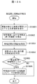
- FIG. 12A and 12B are diagrams illustrating a processing flow of the operation detection method according to the first embodiment.
- FIG. 12A is a flow of detection of the degree of approach and the contact point
- FIG. 12B is a flow of detection of the pointing direction.
- the shadow region extraction unit 104 obtains a difference image by subtracting the background from the image captured by the camera 100, and extracts a portion whose luminance is equal to or less than the threshold value Lth as a shadow region. At this time, a so-called labeling process is performed in which shadow areas that are not connected to each other are distinguished from each other as different shadows.
- the feature point detection unit 105 detects a feature point for each shadow subjected to the labeling process. For example, as shown in FIG. 6, the tip positions of the shadows 401 and 402 are detected as feature points 601 and 602.
- the distance d between the two detected feature points 601 and 602 is measured.
- the contact point detection unit 107 detects the contact point between the finger 30 and the projectile 204. For example, as shown in FIG. 8, the midpoint P of the two feature points 601 and 602 is used as a contact point, and the coordinates are calculated. If the feature point setting method is different from the above (tip position), the contact point position may be corrected according to the setting method.
- the above processing flow is repeatedly executed to detect the operation following the change in the operation state.
- the shadow area extraction unit 104 subtracts the background from the image captured by the camera 100 to obtain a difference image, and extracts a part whose luminance is equal to or less than the threshold value Lth as a shadow area. This is the same as S1001.
- the contour detection unit 108 detects a contour line (substantially straight line portion) for each shadow subjected to the labeling process. For example, as shown in FIG. 11C, contour lines 501 and 502 inside shadows 401 and 402 are detected. At this time, a curved portion such as a fingertip is removed from these contour lines, and a substantially straight line segment is detected.
- the direction detection unit 109 determines that the middle line inclination direction 703 of each of the contour lines 501 and 502 is the pointing direction. Note that the pointing direction may be determined by the method shown in FIG. 11A or 11B.
- the above processing flow is repeatedly executed to detect the operation following the change in the operation state.
- the approach and contact point detection processing of FIG. 12A and the pointing direction detection processing of FIG. 12B can be performed in parallel.
- FIG. 13 is a diagram illustrating an example of control according to the degree of finger approach in the display control unit 121.
- the operation mode and the pointer display are switched according to the degree of approach A between the finger 30 and the projectile 204.
- the contact operation mode is set at level 5 (contact state) where the degree of approach A is the highest.
- the operation mode is switched to the aerial operation mode at levels 4 and 3 where the approach degree A is relatively high, and to the operation off mode at levels 2 and 1 where the approach degree A is relatively low.
- the user 3 can operate the operation target device in a state where the user 3 is lifted from the projectile 204 in addition to the state where the finger 30 is in contact with the projectile 204.
- the operation is switched to the operation off mode, and an operation unintended by the user can be prevented.
- the pointer display switching is performed so that the pointer is displayed at levels 5 and 4 where the approach degree A is relatively high, and is not displayed at 3, 2 and 1 where the approach degree A is relatively low.
- the user 3 can confirm the pointer before the finger 30 comes into contact with the projectile 204, and the position of the pointer at the time of contact can be easily adjusted.
- the operability to the operation target device is improved.
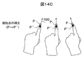
- FIG. 14A to 14C are diagrams illustrating an example of control according to the pointing direction in the display control unit 121.
- FIG. 14A to 14C are diagrams illustrating an example of control according to the pointing direction in the display control unit 121.
- FIG. 14A shows a case where the display position of the pointer 800 is corrected according to the pointing direction 700.
- the pointer 800 if the pointer 800 is displayed at the same position as the contact point P detected by the contact point detection unit 107, the pointer 800 is hidden by the finger 30 and becomes difficult to be seen by the user 3. Therefore, the pointer 800 is displayed by being shifted by a predetermined amount in front of the fingertip along the pointing direction 700 detected by the direction detecting unit 109. As a result, the pointer 800 is easy to see from the user 3.
- the display position shift amount (correction amount) of the pointer 800 may be changed in accordance with the approach degree A of the finger 30. For example, the correction amount is increased when the approach degree A is low, and the correction amount is decreased when the approach degree A is high. Thereby, as the finger 30 of the user 3 approaches the projectile 204, the position of the pointer 800 approaches the fingertip, and the user 3 can perform a highly accurate operation by using the display position of the pointer 800 as a guide.
- FIG. 14B shows a case where the display direction of the pointer 800 is corrected according to the pointing direction 700.
- the display direction of the pointer 800 is displayed in accordance with the pointing direction 700 detected by the direction detection unit 109. As a result, the discrepancy with the pointing direction 700 is eliminated, and a sense of discomfort with the user 3 can be eliminated.
- FIG. 14C shows a case where the position of the contact point is corrected according to the pointing direction 700. Since the contact point P detected by the contact point detection unit 107 is determined from the position of the feature point, it may deviate from the position where it actually contacts the projectile 204. For example, when the feature point is set as the shadow tip position, it shifts to the finger tip side (nail tip) position rather than the actual contact position (often the part of the finger belly). Therefore, the contact point position is corrected by a predetermined amount on the base side of the finger along the pointing direction 700 detected by the direction detection unit 109 (P ⁇ P ′′). Thereby, the contact point between the finger 30 and the projectile 204 is determined. It can be acquired more accurately.
- the above is the detection method of the operation content of the user 3 by the pointing detection in the projection display device 205 with an operation detection function.
- the operation can be performed if there is an elongated object including the finger. This is much easier to use than the light-emitting pen method in which a predetermined light is emitted from the pen tip and the recognition process is performed, and it is not necessary to secure a dedicated light-emitting pen or the like.
- the number of display screens before operation, display orientation, display position, display size, etc. are determined by a method such as the following example.
- a display screen setting set by default in the projection display device with operation detection function 205 may be used.
- the user may manually set the number of display screens, display orientation, display size, etc. by setting conditions.
- the direction in which the finger or arm is inserted is estimated and the position where the person exists is identified, or the number of users is identified from the number of fingers or arms that are inserted. You may make it set the display direction and the number of display screens which are easy to do.
- the number and position of users, the shape of the projectile, etc. may be recognized, and the number of display screens, display position, display orientation, display size, etc. may be determined accordingly.
- the projection display device installed on the desk is close to the recognized object or shielded from the recognized object by an obstacle. This is advantageous because it is less frequent.
- FIGS. 15 to 18 show examples of a method for determining the display orientation of the display screen by recognizing the shape of the projectile.
- FIGS. 15 and 16 show examples of projection onto a rectangular desk. As shown in FIG. 15, the fact that the user 3 is in the vicinity of the projection 204 that is a rectangular desk is photographed and recognized by the camera 100 of the projection display device 205 with an operation detection function. Furthermore, the position of the edge of the desk of the closest part 302 between the user 3 and the edge of the desk is recognized. The display direction is determined in such a direction that the edge direction of the position 302 is parallel to the bottom of the display image and the position of 302 is on the lower side, that is, the display image 202 as shown in FIG.
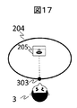
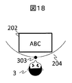
- FIGS. 17 and 18 are examples of projection onto a circular desk.
- the fact that the user 3 is in the vicinity of the projectile 204, which is a circular desk, is photographed and recognized by the camera 100 of the projection display device 205 with operation detection function. Further, the position of the desk edge of the closest part 303 between the user 3 and the desk edge is recognized.
- the display direction is determined in such a direction that the edge direction of the position 303 is parallel to the bottom of the display image and the position of 303 is on the lower side, that is, the display image 202 as shown in FIG.
- FIGS. 15 to 18 an example in which the position of the user 3 and the shape of the projectile are photographed by the camera 100 has been shown.
- the camera 100 basically photographs the operation of the user 3 by detecting the pointing. Therefore, another camera for photographing the position of the user 3 and the shape of the projectile may be provided.
- FIG. 3 when a plurality of images are displayed, the same operation is performed on the positions of a plurality of people, and the display directions are determined.
- 19 and 20 show an example in which a plurality of display images are displayed. In both cases, a plurality of persons and their positions are detected, and the display position and the display direction are determined from the position and shape of the desk edge closest to the position.
- the display direction can be automatically determined from the shape of the edge of the desk closest to the user 3.
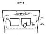
- FIGS. 21A to 24B show an example in which the display screen determined by these methods is operated by a screen operation by the user 3 gesture. It is assumed that the fingertip shown in each figure is in contact with the projectile 204.
- FIG. 21A shows a state before operation
- FIG. 21B shows a state after operation. The same applies to FIGS. 22A to 24B.
- the maximum range 210 in which the projection display device 205 can optically project an image is indicated by a broken line.
- the display screens 202 and 203 are displayed within the display range of the maximum projection range 210 like OSD. That is, the display screens 202 and 203 are partial images in the projectable range 210.
- 21A and 21B are examples of parallel movement.
- the finger touching the display screen 203 is moved in the vertical direction, the horizontal direction, or the licking direction without changing the orientation.
- the display screen in which the finger is in contact moves as much as the movement of the finger. This makes it possible to move one of the display screens to a position desired by the user.
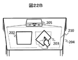
- 22A and 22B are examples of rotational movement.
- the finger touching the display screen 203 is rotated.
- FIG. 22B only the display screen in contact with the finger in the display screen rotates the display direction in accordance with the movement of the finger. This makes it possible to rotate one of the display screens in the direction desired by the user.
- the pointing direction can be detected. Therefore, as shown in FIG. 22B, the rotation operation of the display screen can be realized even when the direction of the finger is rotated without changing the position of the contact point itself. This is a rotation operation that is difficult to achieve with a touch sensor such as a tablet terminal, and can be realized only with the configuration of this embodiment.
- the size of the display screen before the rotation is determined based on the relationship between the shape of the optically projectable range of the projection display device 205 and the position and shape of the display screen to be rotated. It may not be possible to rotate. In this case, the display screen may be reduced in parallel with the rotation operation. If the display screen needs to be reduced when rotating in one direction, the display screen is reduced by rotating it halfway, and then returned to the original angle when rotated in the opposite direction. You may return to the original size.
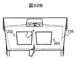
- 23A and 23B are examples of operations for increasing the number of display screens.
- the finger touching the outside of the display screen 200 is moved toward the outside of the opposite side to move the display screen in half.
- two screens that display the same content as the content displayed on the display screen 200, such as cell division, are created from where the display screen is cut in half (display screens 202 and 203). ). This makes it possible to increase the number of display screens as desired by the user.
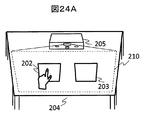
- 24A and 24B are examples of operations for enlarging the display screen. Position the two fingers in contact with the display screen 202 in FIG. 24A as if they were placed on the opposite vertices of the rectangle, and push the diagonal line connecting the opposite vertices in FIG. Increase the distance. Then, the screen is enlarged by the amount that only the operated display screen 202 is expanded. If it is moved in the reverse direction, an operation can be performed in which the screen is reduced and an area outside the display screen 202 is displayed. As a result, the display screen can be enlarged or reduced as desired by the user.
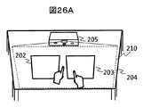
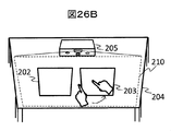
- 25A and 25B are examples of rotating the display screen 203 by operating two fingers. As shown in FIG. 25A, when both two fingers are in contact with the desk in the display screen 203, the inclination of the straight line connecting the contact points of the two fingers changes as shown in FIG. 25B. If it is detected that two fingers have moved, the projection display device with operation detection function 205 changes the display angle of the display screen 203 to correspond to the change in the tilt. As a result, the display screen can be rotated.
- both of the contact points of the two fingers are not in one display screen (for example, one In the case where only the contact point of the finger is within the display screen 203 and the contact point of the other finger is outside the display screen 203), the slope of the straight line connecting the contact points of the two fingers as shown in FIG. Even if two fingers move so as to change, the display angle of the display screen 203 may not be changed.
- the control unit 110 detects two fingers having a time difference of less than 1 second in contact with the desk, and the combinations of the two fingers are shown in FIGS. 25A to 26B. What is necessary is just to judge that it is the combination of the finger
- the contact position of these two fingers used in the determination process for the contact position of these two fingers and the range of the display screen 203 is the first position where these two fingers contact the desk from the air. May be used.
- the display screen rotation process need not be started.
- the determination of whether or not to start the rotation process can be simplified by determining only the first position where two fingers contact the desk from the air, and the control unit 110 There is an effect that the processing efficiency is improved.
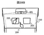
- FIGS. 27A and 27B are examples in which the display screen 202 is enlarged by operating two fingers.
- FIG. 27A when both two fingers are in contact with the desk in the display screen 202, the distance of the straight line connecting the contact points of the two fingers is increased as shown in FIG. 27B.
- the projection display device with operation detection function 205 changes the display size of the display screen 202 so as to correspond to the change in the length. Thereby, the display screen can be enlarged.
- the display screen is reduced.
- the control unit 110 may determine the target finger combination. For example, among the plurality of fingers detected by the camera 100, the control unit 110 detects two fingers having a time difference of less than 1 second in contact with the desk, and the combinations of the two fingers are shown in FIGS. 27A to 28B. What is necessary is just to judge that it is the combination of two fingers made into object by the process demonstrated by (1).
- the contact position of these two fingers and the contact position of these two fingers used in the determination process for the range of the display screen 202 described above are the first positions where these two fingers contact the desk from the air. May be used. When these fingers move from the outside of the display screen 202 while touching the desk, the display screen size changing process need not be started.
- the determination as to whether or not to start the resizing process can be simplified by determining only the first position where two fingers touch the desk from the air, and the control unit 110 can be simplified. This has the effect of improving the processing efficiency.
- the determination process described above it is possible to clearly identify the display screen that is the target of the size change processing operation among the plurality of display screens.
- the projection display device with an operation detection function that can be installed on a desk can perform an operation by pointing detection and the like with high accuracy.
- Example 2 of the present invention will be described.
- the projection display device with an operation detection function shown in FIG. 2 includes illuminations 101 and 102, and a method for detecting shadows of illumination light from two different directions is shown in Example 1. If visible light is used as the illumination light, a shadow generated by a pointing operation is reflected on the display screen, which may make it difficult to see the display screen. In view of this, it is preferable to use illumination of visible light such as infrared light as illumination light, and to use a corresponding camera such as an infrared camera as the camera 100.
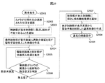
- Fig. 29 shows a flowchart for operating this function.
- the control unit 110 determines that the pointing cannot be detected from the image captured by the camera, and notifies the display control unit 111 of it.
- Detection standards include objects such as fingers that are not detected in advance for a long time, visible light is blocked over a wide area, and objects that do not move for a long time. Take as an example.
- the display control unit 111 creates a video in which a warning caption such as “abnormal pointing detection. Check for foreign objects between the camera and the illumination unit and the display screen” is inserted in the display screen, and the video created in S2005. Is displayed. This display is continued until the camera 100 captures the situation where the blocker of visible light is removed.
- control unit 110 determines from the image captured by the camera 100 whether or not the blocker of visible light is removed. If the light blocker is removed, in S2007, the control unit 110 notifies the display control unit 111 that the pointing detection function has been restored.
- the display control unit 111 creates a normal display screen from which the warning subtitle is deleted, and returns to the normal display screen in S2009.
- the above is an example of a series of operations.
- Example 3 of the present invention will be described.
- the projection display device described in the first embodiment of the present invention various screen operations can be performed by a viewer's gesture operation (pointing operation) as described above.
- the operations that can be input in the projection display device according to the present embodiment are operations that cannot be performed with a finger touch detection type tablet, and the user may be unfamiliar. Therefore, the projection display device according to the third embodiment of the present invention includes an operation guide display function in addition to the configuration and function of the projection display device according to the first or second embodiment.
- FIG. 30 shows an example of the operation guide display in the present embodiment.
- the projection display device 205 displays one display content on the display screen 3000 projected onto the desk. The vertical and horizontal directions in the display content are as shown in the figure.
- a plurality of operation guide displays 3001, 3002, and 3003 are displayed at different angles with respect to this display content.
- An example of the operation guide display is a so-called OSD (on-screen display), and the display control unit 111 is controlled by the control unit 110 based on data stored in a storage unit (not shown) inside the projection display device 205. Is superimposed on the input signal.
- OSD on-screen display
- a gesture operation can be performed on the side A. It is unlikely that there will be viewers.
- display content is displayed in an easy direction, if only the operation guide 3001 in the same direction as the top, bottom, left, and right of the display content is displayed, viewers existing on the remaining two sides (for example, sides B and D) The user does not know how to operate, and must move to the position of side C.
- each of the three sides B, C, and D is displayed. May be displayed so as to correspond to the left and right directions of the plurality of operation guide displays 3001, 3002, and 3003. If displayed in this way, for example, any of viewers existing on the other three sides B, C, and D other than the direction of one side A where the projection display device 205 is installed can be operated. It becomes easy to understand how.
- the operation guide display may be a diagram illustrating an operation gesture, a diagram illustrating the operation gesture and its explanatory text, a text describing the operation gesture, or an animation indicating the operation gesture. Or a combination of these may be used.
- the operation guide display timing may be the timing of operation input of a remote control button (not shown).
- a question mark may be displayed in a small corner at one corner of the display screen, and the operation guide display as shown in FIG. 30 may be performed at the timing when the viewer's finger touch or gesture operation on the question mark is detected.
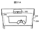
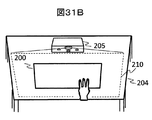
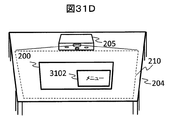
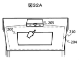
- FIGS. 31A to 31D show operations when displaying detailed information of a display image and displaying a menu screen when the projection display device 205 displays one display screen 200 on the desk 204.
- FIG. 31A to 31D show operations when displaying detailed information of a display image and displaying a menu screen when the projection display device 205 displays one display screen 200 on the desk 204.
- a gesture in which two fingers with different pointing directions are in contact as shown in FIG. 31A may be used.
- the two contact points do not have to be completely in contact with each other, and may be set to be a predetermined distance or less set in design.
- a gesture in which three fingers are in contact with the display surface as shown in FIG. 31B is used. Also good.
- gestures shown in FIGS. 31A and 31B are examples, and other gestures may be used as long as they are distinguishable from other operations.
- the control unit 110 of the projection display device 205 determines that it is a detailed information display operation, and displays detailed information 3101 as shown in FIG. 31C. To do.
- the control unit 110 of the projection display device 205 determines that the operation is a menu screen display operation, and the menu screen is displayed as shown in FIG. 31D. 3102 is displayed.
- the control unit 110 of the projection display device 205 determines that the operation is to perform both detailed information display and menu screen display.
- the detailed information 3101 shown in 31C and the menu screen 3102 shown in FIG. 31D may be displayed together.
- the display position of the detailed information 3101 shown in FIG. 31C and the display position of the menu screen 3102 shown in FIG. 31D may be displayed in a predetermined position in or near the display screen 200.
- the detailed information 3101 is displayed at a position corresponding to the contact point of the finger of the gesture shown in FIG. 31A or the position (position of the middle finger of the three fingers) where the gesture shown in FIG. 31B is detected.
- the menu screen 3102 may be displayed.
- An example of the detailed information 3101 may be the nature of the displayed video (input resolution, frame rate, interlace, progressive, etc.), and if the input video includes supplementary information such as title information. This information may be acceptable. Further, in the case of a projection display device having a plurality of input terminals and capable of inputting video from different input sources, information for identifying these input sources may be used.
- menu items displayed on the menu screen 3102 may include a language switching menu used in the menu, an image quality adjustment menu such as brightness and contrast of a display image, and a keystone correction processing menu.
- a menu item for switching the input source may be displayed.
- FIGS. 32A and 32B are gestures for increasing the number of display screens and display examples thereof similar to those in FIGS. 23A and 23B, and the description thereof is omitted because it has already been described in the first embodiment.
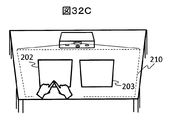
- FIG. 32C shows an example in which the gesture shown in FIG. 31A is detected at a position where the touch point of the finger is included in the display screen 202 among the plurality of display screens 202 and 203 generated by the operation for increasing the number of display screens. Show.
- the control unit 110 of the projection display device 205 displays individual detailed information or individual menu screen display about the display screen 202 in the vicinity of the display screen 202 (or within the screen). Or display combining these.
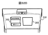
- the individual menu screen shown in FIG. 32D displays individual menu items for the display screen 202.
- an image quality adjustment menu for the display image on the display screen 202 (not for adjusting the image quality for the display image on the display screen 203) may be displayed.
- switching of the input source of the display video displayed on the display screen 202 (input about the display video on the display screen 203) Menu items for performing source switching) may be displayed.
- the menu item for keystone correction is not displayed in the individual menu display for the display screen 202. It is good also as an aspect which cannot be operated even if it displays.
- the individual detailed information shown in FIG. 32D displays individual detailed information about the display screen 202. What is necessary is just to display the information etc. which identify input sources, such as the property of the image
- the input source can be switched from the menu screen for the display screen 202 shown in FIG. 32D.
- the properties, title information, input source, and the like of the images displayed on the display screen 202 and the display screen 203 are different, it is useful for the viewer that the detailed information on each display screen can be confirmed individually. .
- FIGS. 32A to 32D the example of the gesture of FIG. 31A is used as the gesture for displaying the individual detailed information or the individual menu screen, but the gesture of FIG. 31B may be used.
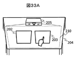
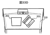
- FIG. 33A to FIG. 33D after the display screen rotation operation described in FIG. 22A, FIG. 22B, FIG. 25A, and FIG. 25B is performed, individual detailed information display or individual menu screen display for each display screen is performed. An example of performing this will be described.
- FIG. 33A and FIG. 33B are display screen rotation operation gestures similar to those shown in FIG. 22A and FIG. 22B and their display examples. Since they have already been described in the first embodiment, description thereof will be omitted.
- FIG. 33C shows a state in which one display screen 203 among the plurality of display screens 202 and 203 is rotated by the rotation operation of the display screen, and the position where the finger contact point is included in the display screen 203 is shown in FIG. An example in which the illustrated gesture is detected is illustrated.
- the control unit 110 of the projection display device 205 displays individual detailed information or individual menu screen display about the display screen 203 in the vicinity of the display screen 203 (or within the screen).
- the individual detailed information display or the individual menu screen display is performed at an angle corresponding to the display angle of the display screen 203.
- the contents of the individual detailed information display or the individual menu screen display for the display screen 203 are the same as the description for the display screen 202 in FIGS. 32A to 32D, and therefore the repetitive description is omitted.
- FIG. 33A to FIG. 33D the example of the gesture of FIG. 31B is used as the gesture for displaying the individual detailed information or the individual menu screen, but the gesture of FIG. 31A may be used.
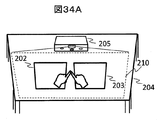
- FIGS. 34A to 34D an example will be described in which, when a plurality of display screens are displayed, an entire menu for all display screens is displayed instead of individual menus for each screen.
- the gestures similar to those of FIG. 31A or FIG. 31B are used as gestures for displaying the entire menu, as in FIGS. 32A to 32D and 33A to 33D.
- this is different from FIGS. 32A to 32D and FIGS. 33A to 33D.
- the contact point of the finger of the gesture in FIG. 31A is detected outside a plurality of display screens, it is determined as a gesture for starting the entire menu display.
- three fingers in the same gesture as in FIG. 31B are detected outside a plurality of display screens, the gesture is determined as a gesture for starting the entire menu display. This will be specifically described below with reference to the drawings.
- the projection display device 205 displays the display screen 202 and the display screen 203 on the desk 204.
- the gesture of FIG. 31A is detected, and the contact point of the finger is detected at a position that is neither the display screen 202 nor the display screen 203.
- the control unit 110 of the projection display device 205 controls the display control unit 111 to display the entire menu 3401 as shown in FIG. 34B. Further, overall detailed information 3402 that is detailed information about the entire screen may be displayed.
- the menu item of the overall menu 3401 may display a menu for overall image quality adjustment that simultaneously adjusts the image quality of display images on all display screens.
- a language switching menu item for switching the language used in the entire menu may be displayed.
- trapezoidal correction menu items that could not be used in individual menu display on individual screens may be used in the overall menu 3401.
- the number of display screens may be used. Further, in the case of a projection display device having a plurality of input terminals and capable of inputting video from different input sources, a plurality of display screens and a list of input sources may be displayed.
- the gesture of FIG. 31B may be used instead of the gesture of FIG. 31A.
- the projection display device 205 displays the display screen 202 and the display screen 203 on the desk 204, but the display screen 203 is displayed at a different angle from the display screen 202 by the rotation process.
- the gesture of FIG. 31A is detected, and the contact point of the finger is detected at a position that is neither the display screen 202 nor the display screen 203.
- the control unit 110 of the projection display device 205 controls the display control unit 111 to display the entire menu 3401 as shown in FIG. 34D.
- individual detailed information 3403 and 3404 may be displayed for each of the plurality of display screens.
- a menu item for setting ON / OFF of each gesture recognition function described in each embodiment may be provided.
- all the gesture recognition functions may be turned off.
- the projection display device 205 is operated based on an operation signal corresponding to a button operation on the remote controller or the main body.
- the one-finger movement gesture recognition process shown in FIG. 21A and the one-finger rotation gesture recognition process shown in FIG. 21B may be individually turned off. This is effective when there is a possibility of misrecognition when explaining with a stick.
- a menu item for selecting whether to recognize the one-finger rotation gesture shown in FIG. 21B or the two-finger rotation gesture shown in FIGS. 25A and 25B may be displayed.
- the projection display device 205 there are cases where there is a merit in setting ON / OFF individually for each gesture recognized by the projection display device 205.
- all the gestures described in FIG. 21A and after may be configured so that ON / OFF can be set from the menu screen.
- the ON / OFF setting of these gestures may be applied only to the corresponding display screen.
- 100 camera, 101, 102: illumination, 104: shadow area extraction unit, 105: feature point detection unit, 106: proximity detection unit, 107: contact point detection unit, 108: contour detection unit, 109: direction detection unit, 110: control unit, 111: display control unit, 112: drive circuit unit, 113: input terminal, 114: input signal processing unit, 115: projection unit, 201: projection display device, 202, 203: display screen, 204: Projection, 205: Projection display device with operation detection function, 3: User, 30, 31, 32: Finger, 401, 402, 403, 404, 405: Shadow, 501, 502: Outline, 601, 602: Features Point: 700, 701, 702, 703: Pointing direction, 800: Pointer, P: Contact point.
Landscapes
- Engineering & Computer Science (AREA)
- General Engineering & Computer Science (AREA)
- Theoretical Computer Science (AREA)
- Physics & Mathematics (AREA)
- General Physics & Mathematics (AREA)
- Human Computer Interaction (AREA)
- Multimedia (AREA)
- Signal Processing (AREA)
- Computer Hardware Design (AREA)
- Geometry (AREA)
- User Interface Of Digital Computer (AREA)
- Position Input By Displaying (AREA)
- Controls And Circuits For Display Device (AREA)
Abstract
Description
Claims (11)
- 映像を投射する映像投射部と、
前記映像投射部が投射する映像投射面と少なくとも一部が重なる面に前記投射映像とは異なる照明光を照射する少なくとも1つの照明部と、
前記照明光の反射光により撮像を行う撮像部と、
前記撮像部が撮像した画像に基づいて操作者の指が前記映像投射面に接する少なくとも位置を検出する検出部と、
前記検出部による検出結果に基づいて前記映像投射部が投射する映像の含む少なくとも一つの部分映像を変更するよう制御する表示制御部と
を有することを特徴とする投射型映像表示装置。 - 請求項1に記載の投射型映像表示装置であって、
前記検出部は、さらに、操作者の指の方向を検出する
ことを特徴とする投射型映像表示装置。 - 請求項1または請求項2に記載の投射型映像表示装置であって、
前記映像投射部が映像を投射する映像投射面と少なくとも一部が重なる面に、前記投射映像とは異なる照明光を互いに異なる位置から照射する2つの照明部
を有することを特徴とする投射型映像表示装置。 - 請求項1に記載の投射型映像表示装置であって、
前記検出部が、前記操作者の指の前記映像投射面に接する位置が移動したことを検出した場合には、
前記表示制御部は、前記映像投射部が投射する映像のうち前記指が位置する部分映像を前記指の移動に基づいて移動する
ことを特徴とする投射型映像表示装置。 - 請求項1に記載の投射型映像表示装置であって、
前記検出部が、前記操作者の指の前記映像投射面に接する方向が回転したことを検出した場合には、
前記表示制御部は、前記映像投射部が投射する映像のうち前記指が位置する部分映像を前記指の方向に基づいて回転する
ことを特徴とする投射型映像表示装置。 - 請求項1に記載の投射型映像表示装置であって、
前記検出部が、前記操作者の指が前記映像投射面に接しながら前記部分映像を横断したことを検出した場合には、
前記表示制御部は、前記映像投射部が投射する映像のうち前記部分映像を前記指が横断した位置と方向に基づいて分割する
ことを特徴とする投射型映像表示装置。 - 請求項1に記載の投射型映像表示装置であって、
前記検出部が、前記操作者の二本の指の前記映像投射面に接する位置間隔が拡大又は縮小したことを検出した場合には、
前記表示制御部は、前記映像投射部が投射する映像のうち前記二本の指が位置する部分映像を前記二本の指が移動した方向に基づいて拡大又は縮小する
ことを特徴とする投射型映像表示装置。 - 請求項1に記載の投射型映像表示装置であって、
前記映像投射部が投射する映像は、複数の前記部分映像を含み、
前記検出部において、前記操作者の指が前記部分映像に接した時に前記指の方向を含め所定の方法で接したことを検出した場合には、
前記表示制御部は、前記部分映像に固有なメニュー表示画面を前記部分映像に表示するよう前記映像投射部を制御する
ことを特徴とする投射型映像表示装置。 - 請求項1に記載の投射型映像表示装置であって、
前記映像投射部が投射する映像は、複数の前記部分映像を含み、
前記検出部において、前記操作者の指が前記部分映像のいずれにも含まれない映像投射面に接した時に前記指の方向を含め所定の方法で接したことを検出した場合には、
前記表示制御部は、前記映像表示面の全体に係るメニュー表示画面を前記映像表示面に表示するよう前記映像投射部を制御する
ことを特徴とする投射型映像表示装置。 - 請求項1に記載の投射型映像表示装置であって、
前記映像投射面の面上に設置されて前記映像を投射する
ことを特徴とする投射型映像表示装置。 - 請求項1に記載の投射型映像表示装置であって、
前記検出部が前記操作者の指の位置を検出する際の障害物を検出した場合には、
前記表示制御部は、障害物を検出したことを前記操作者に知らせるための映像を投射するよう前記映像投射部を制御する
ことを特徴とする投射型映像表示装置。
Priority Applications (6)
| Application Number | Priority Date | Filing Date | Title |
|---|---|---|---|
| US15/037,164 US9927923B2 (en) | 2013-11-19 | 2013-11-19 | Projection-type video display device |
| PCT/JP2013/081131 WO2015075767A1 (ja) | 2013-11-19 | 2013-11-19 | 投射型映像表示装置 |
| CN201380080630.8A CN105706028B (zh) | 2013-11-19 | 2013-11-19 | 投影型影像显示装置 |
| JP2015548896A JP5973087B2 (ja) | 2013-11-19 | 2013-11-19 | 投射型映像表示装置 |
| CN201810532207.1A CN108664173B (zh) | 2013-11-19 | 2013-11-19 | 投影型影像显示装置 |
| US15/889,817 US10191594B2 (en) | 2013-11-19 | 2018-02-06 | Projection-type video display device |
Applications Claiming Priority (1)
| Application Number | Priority Date | Filing Date | Title |
|---|---|---|---|
| PCT/JP2013/081131 WO2015075767A1 (ja) | 2013-11-19 | 2013-11-19 | 投射型映像表示装置 |
Related Child Applications (2)
| Application Number | Title | Priority Date | Filing Date |
|---|---|---|---|
| US15/037,164 A-371-Of-International US9927923B2 (en) | 2013-11-19 | 2013-11-19 | Projection-type video display device |
| US15/889,817 Continuation US10191594B2 (en) | 2013-11-19 | 2018-02-06 | Projection-type video display device |
Publications (1)
| Publication Number | Publication Date |
|---|---|
| WO2015075767A1 true WO2015075767A1 (ja) | 2015-05-28 |
Family
ID=53179077
Family Applications (1)
| Application Number | Title | Priority Date | Filing Date |
|---|---|---|---|
| PCT/JP2013/081131 Ceased WO2015075767A1 (ja) | 2013-11-19 | 2013-11-19 | 投射型映像表示装置 |
Country Status (4)
| Country | Link |
|---|---|
| US (2) | US9927923B2 (ja) |
| JP (1) | JP5973087B2 (ja) |
| CN (2) | CN105706028B (ja) |
| WO (1) | WO2015075767A1 (ja) |
Cited By (3)
| Publication number | Priority date | Publication date | Assignee | Title |
|---|---|---|---|---|
| CN106556963A (zh) * | 2015-09-24 | 2017-04-05 | 北京京东尚科信息技术有限公司 | 投影装置以及投影方法 |
| JP2018205478A (ja) * | 2017-06-02 | 2018-12-27 | セイコーエプソン株式会社 | 表示装置および表示装置の制御方法 |
| JP2022076371A (ja) * | 2020-11-09 | 2022-05-19 | 株式会社Nttドコモ | 情報処理装置 |
Families Citing this family (56)
| Publication number | Priority date | Publication date | Assignee | Title |
|---|---|---|---|---|
| US10001898B1 (en) | 2011-07-12 | 2018-06-19 | Domo, Inc. | Automated provisioning of relational information for a summary data visualization |
| US9792017B1 (en) | 2011-07-12 | 2017-10-17 | Domo, Inc. | Automatic creation of drill paths |
| US9202297B1 (en) * | 2011-07-12 | 2015-12-01 | Domo, Inc. | Dynamic expansion of data visualizations |
| WO2015052765A1 (ja) * | 2013-10-08 | 2015-04-16 | 日立マクセル株式会社 | 投射型映像表示装置、操作検出装置及び投射型映像表示方法 |
| WO2016018372A1 (en) * | 2014-07-31 | 2016-02-04 | Hewlett-Packard Development Company, L.P. | White flash generation from a light emitting diode (led) projector |
| EP3062142B1 (en) | 2015-02-26 | 2018-10-03 | Nokia Technologies OY | Apparatus for a near-eye display |
| US11410633B2 (en) * | 2015-11-16 | 2022-08-09 | Verizon Patent And Licensing Inc. | Orientation selection |
| US20170351415A1 (en) * | 2016-06-06 | 2017-12-07 | Jonathan K. Cheng | System and interfaces for an interactive system |
| US11076137B1 (en) * | 2016-06-20 | 2021-07-27 | Amazon Technologies, Inc. | Modifying projected images |
| WO2018042923A1 (ja) * | 2016-08-31 | 2018-03-08 | ソニー株式会社 | 情報処理システム、情報処理方法、およびプログラム |
| US10650552B2 (en) | 2016-12-29 | 2020-05-12 | Magic Leap, Inc. | Systems and methods for augmented reality |
| EP3343267B1 (en) | 2016-12-30 | 2024-01-24 | Magic Leap, Inc. | Polychromatic light out-coupling apparatus, near-eye displays comprising the same, and method of out-coupling polychromatic light |
| WO2018150757A1 (ja) * | 2017-02-17 | 2018-08-23 | ソニー株式会社 | 情報処理システム、情報処理方法、およびプログラム |
| JP6919266B2 (ja) * | 2017-03-28 | 2021-08-18 | セイコーエプソン株式会社 | 光射出装置および画像表示システム |
| US10578870B2 (en) | 2017-07-26 | 2020-03-03 | Magic Leap, Inc. | Exit pupil expander |
| JP2019060963A (ja) * | 2017-09-25 | 2019-04-18 | ソニー株式会社 | 表示処理装置、表示処理方法及びプログラム |
| CN107992191A (zh) * | 2017-10-30 | 2018-05-04 | 捷开通讯(深圳)有限公司 | 一种电子设备及其控制方法、电子设备摄像头模组 |
| CN108093232B (zh) * | 2017-11-08 | 2019-09-13 | 歌尔科技有限公司 | 一种悬挂式投影仪分屏显示的方法、装置和悬挂式投影仪 |
| JP7282090B2 (ja) | 2017-12-10 | 2023-05-26 | マジック リープ, インコーポレイテッド | 光学導波管上の反射防止性コーティング |
| CN111712751B (zh) | 2017-12-20 | 2022-11-01 | 奇跃公司 | 用于增强现实观看设备的插入件 |
| EP4415355A3 (en) | 2018-03-15 | 2024-09-04 | Magic Leap, Inc. | Image correction due to deformation of components of a viewing device |
| JP7650662B2 (ja) | 2018-05-30 | 2025-03-25 | マジック リープ, インコーポレイテッド | 小型の可変焦点構成 |
| CN112601975B (zh) | 2018-05-31 | 2024-09-06 | 奇跃公司 | 雷达头部姿势定位 |
| US10825424B2 (en) | 2018-06-05 | 2020-11-03 | Magic Leap, Inc. | Homography transformation matrices based temperature calibration of a viewing system |
| JP7421505B2 (ja) * | 2018-06-08 | 2024-01-24 | マジック リープ, インコーポレイテッド | 自動化された表面選択設置およびコンテンツ配向設置を用いた拡張現実ビューア |
| WO2020010097A1 (en) | 2018-07-02 | 2020-01-09 | Magic Leap, Inc. | Pixel intensity modulation using modifying gain values |
| US11510027B2 (en) | 2018-07-03 | 2022-11-22 | Magic Leap, Inc. | Systems and methods for virtual and augmented reality |
| US11856479B2 (en) | 2018-07-03 | 2023-12-26 | Magic Leap, Inc. | Systems and methods for virtual and augmented reality along a route with markers |
| JP7374981B2 (ja) | 2018-07-10 | 2023-11-07 | マジック リープ, インコーポレイテッド | クロス命令セットアーキテクチャプロシージャ呼出のためのスレッドウィービング |
| WO2020023543A1 (en) | 2018-07-24 | 2020-01-30 | Magic Leap, Inc. | Viewing device with dust seal integration |
| US11598651B2 (en) | 2018-07-24 | 2023-03-07 | Magic Leap, Inc. | Temperature dependent calibration of movement detection devices |
| EP4650919A3 (en) | 2018-08-02 | 2026-01-21 | Magic Leap, Inc. | A viewing system with interpupillary distance compensation based on head motion |
| EP3830631A4 (en) | 2018-08-03 | 2021-10-27 | Magic Leap, Inc. | DRIFT CORRECTION BASED ON UNMERGED LAYING OF MELTED LAYING OF A TOTEM IN A USER INTERACTION SYSTEM |
| JP7487176B2 (ja) | 2018-08-22 | 2024-05-20 | マジック リープ, インコーポレイテッド | 患者視認システム |
| USD895664S1 (en) * | 2018-08-24 | 2020-09-08 | Microsoft Corporation | Display screen with animated graphical user interface |
| USD933079S1 (en) | 2018-08-24 | 2021-10-12 | Microsoft Corporation | Display screen with animated graphical user interface |
| USD915451S1 (en) | 2018-08-24 | 2021-04-06 | Microsoft Corporation | Display screen with animated graphical user interface |
| CN113196138B (zh) | 2018-11-16 | 2023-08-25 | 奇跃公司 | 用于保持图像清晰度的图像尺寸触发的澄清 |
| USD896269S1 (en) * | 2018-12-11 | 2020-09-15 | Beijing Microlive Vision Technology Co., Ltd. | Display screen or portion thereof with an animated graphical user interface |
| CN109509407B (zh) * | 2018-12-12 | 2021-12-10 | 深圳市万普拉斯科技有限公司 | 显示装置 |
| JP7543274B2 (ja) | 2018-12-21 | 2024-09-02 | マジック リープ, インコーポレイテッド | 導波管内の全内部反射を助長するための空気ポケット構造 |
| USD904432S1 (en) * | 2019-01-04 | 2020-12-08 | Samsung Electronics Co., Ltd. | Display screen or portion thereof with transitional graphical user interface |
| USD904431S1 (en) * | 2019-01-04 | 2020-12-08 | Samsung Electronics Co., Ltd. | Display screen or portion thereof with transitional graphical user interface |
| USD920997S1 (en) * | 2019-01-04 | 2021-06-01 | Samsung Electronics Co., Ltd. | Refrigerator with transitional graphical user interface |
| EP3939030B1 (en) | 2019-03-12 | 2025-10-29 | Magic Leap, Inc. | Registration of local content between first and second augmented reality viewers |
| CN120812326A (zh) | 2019-05-01 | 2025-10-17 | 奇跃公司 | 内容提供系统和方法 |
| CN110119208B (zh) * | 2019-05-15 | 2021-04-30 | 京东方科技集团股份有限公司 | 悬浮显示成像装置及悬浮显示触控方法 |
| WO2021021670A1 (en) | 2019-07-26 | 2021-02-04 | Magic Leap, Inc. | Systems and methods for augmented reality |
| US12033081B2 (en) | 2019-11-14 | 2024-07-09 | Magic Leap, Inc. | Systems and methods for virtual and augmented reality |
| EP4058979A4 (en) | 2019-11-15 | 2023-01-11 | Magic Leap, Inc. | VISUALIZATION SYSTEM FOR USE IN A SURGICAL ENVIRONMENT |
| CN111831161B (zh) * | 2020-07-23 | 2023-10-03 | 吕嘉昳 | 基于触摸方法自动识别显示屏幕中触点位置的方法 |
| CN112306442B (zh) * | 2020-11-20 | 2023-05-12 | Oppo广东移动通信有限公司 | 跨设备的内容投屏方法、装置、设备及存储介质 |
| JP7625869B2 (ja) * | 2021-01-25 | 2025-02-04 | セイコーエプソン株式会社 | 表示装置の制御方法及び表示装置 |
| CN112929734B (zh) * | 2021-02-05 | 2023-09-05 | 维沃移动通信有限公司 | 投屏方法、装置和电子设备 |
| CN114442851B (zh) * | 2022-01-28 | 2024-11-22 | 深圳Tcl新技术有限公司 | 激光处理方法、装置、存储介质、显示设备及激光设备 |
| CN115278185B (zh) * | 2022-07-29 | 2024-07-02 | 歌尔科技有限公司 | 投影区域检测方法、装置、桌面投影机及存储介质 |
Citations (14)
| Publication number | Priority date | Publication date | Assignee | Title |
|---|---|---|---|---|
| JPH08320921A (ja) * | 1995-05-25 | 1996-12-03 | Oki Electric Ind Co Ltd | ポインティングシステム |
| JP2005148555A (ja) * | 2003-11-18 | 2005-06-09 | Ricoh Co Ltd | 画像投影表示装置、画像投影表示方法および画像投影表示プログラム |
| JP2005318268A (ja) * | 2004-04-28 | 2005-11-10 | Fuji Electric Systems Co Ltd | 投射表示装置および投射表示システム |
| JP2009064109A (ja) * | 2007-09-04 | 2009-03-26 | Canon Inc | 画像投影装置及びその制御方法 |
| JP2009237337A (ja) * | 2008-03-27 | 2009-10-15 | Sanyo Electric Co Ltd | 投写型映像表示装置及びこれを用いた投写型映像表示システム |
| JP2010237347A (ja) * | 2009-03-31 | 2010-10-21 | Hitachi Ltd | 投射型表示装置 |
| JP2011004386A (ja) * | 2009-06-19 | 2011-01-06 | Avaya Inc | プラガブルコンタクトレゾリューション |
| US20110185300A1 (en) * | 2010-01-28 | 2011-07-28 | Microsoft Corporation | Brush, carbon-copy, and fill gestures |
| WO2011118313A1 (ja) * | 2010-03-24 | 2011-09-29 | 株式会社日立ソリューションズ | 座標入力装置及びプログラム |
| JP2012104096A (ja) * | 2010-10-14 | 2012-05-31 | Nikon Corp | プロジェクタ |
| JP2012113653A (ja) * | 2010-11-26 | 2012-06-14 | Canon Inc | 制御装置、入力装置、入力判定方法、プログラム |
| WO2012120958A1 (ja) * | 2011-03-04 | 2012-09-13 | 株式会社ニコン | 投影装置 |
| JP2012238293A (ja) * | 2011-04-28 | 2012-12-06 | Nextedge Technology Inc | 入力装置 |
| JP2013114647A (ja) * | 2011-12-01 | 2013-06-10 | Exvision Inc | ジェスチャー入力システム |
Family Cites Families (24)
| Publication number | Priority date | Publication date | Assignee | Title |
|---|---|---|---|---|
| US6243074B1 (en) * | 1997-08-29 | 2001-06-05 | Xerox Corporation | Handedness detection for a physical manipulatory grammar |
| KR20030072591A (ko) * | 2001-01-08 | 2003-09-15 | 브이케이비 인코포레이티드 | 데이터 입력 디바이스 |
| JP4700539B2 (ja) | 2006-03-22 | 2011-06-15 | パナソニック株式会社 | 表示装置 |
| CN101038671A (zh) * | 2007-04-25 | 2007-09-19 | 上海大学 | 基于立体视觉三维手指运动轨迹跟踪方法 |
| JP4933389B2 (ja) | 2007-09-14 | 2012-05-16 | 株式会社リコー | 画像投影表示装置、画像投影表示方法、画像投影表示プログラム及び記録媒体 |
| JP5214223B2 (ja) * | 2007-11-15 | 2013-06-19 | 船井電機株式会社 | プロジェクタ |
| JP2009250772A (ja) | 2008-04-04 | 2009-10-29 | Sony Corp | 位置検出システム、位置検出方法、プログラム、物体判断システム、および物体判断方法 |
| JP2010224015A (ja) * | 2009-03-19 | 2010-10-07 | Sanyo Electric Co Ltd | 投写型映像表示装置及び記載ボード及び投写映像システム |
| JP5396975B2 (ja) | 2009-04-01 | 2014-01-22 | 船井電機株式会社 | 画像表示装置 |
| US20100315413A1 (en) * | 2009-06-16 | 2010-12-16 | Microsoft Corporation | Surface Computer User Interaction |
| JP5374266B2 (ja) | 2009-07-22 | 2013-12-25 | 株式会社シロク | 光学式位置検出装置 |
| EP2461237B1 (en) | 2009-07-30 | 2020-06-24 | Sharp Kabushiki Kaisha | Portable display device, control method for the same, program for the same, and storage medium for the same |
| JP2011043876A (ja) | 2009-08-19 | 2011-03-03 | Brother Industries Ltd | 画像表示装置 |
| JP5412227B2 (ja) * | 2009-10-05 | 2014-02-12 | 日立コンシューマエレクトロニクス株式会社 | 映像表示装置、および、その表示制御方法 |
| JP5141701B2 (ja) * | 2010-02-25 | 2013-02-13 | 株式会社ニコン | プロジェクタ |
| JP2012068690A (ja) | 2010-09-21 | 2012-04-05 | Univ Of Tsukuba | 手指ジェスチャ検出装置 |
| JP2012185630A (ja) | 2011-03-04 | 2012-09-27 | Nikon Corp | 投影装置 |
| JP2012194915A (ja) | 2011-03-17 | 2012-10-11 | Seiko Epson Corp | 画像表示システム |
| JP5845783B2 (ja) | 2011-09-30 | 2016-01-20 | カシオ計算機株式会社 | 表示装置、表示制御方法及びプログラム |
| US9354809B2 (en) * | 2011-10-03 | 2016-05-31 | Furuno Electric Co., Ltd. | Display device, display program and display method |
| WO2013051052A1 (ja) | 2011-10-03 | 2013-04-11 | 古野電気株式会社 | 情報表示装置、情報表示方法及び情報表示プログラム |
| JP2013148802A (ja) | 2012-01-23 | 2013-08-01 | Nikon Corp | プロジェクタ |
| JP6037900B2 (ja) * | 2013-03-11 | 2016-12-07 | 日立マクセル株式会社 | 操作検出装置及び操作検出方法 |
| KR102137240B1 (ko) * | 2013-04-16 | 2020-07-23 | 삼성전자주식회사 | 디스플레이 영역을 조절하기 위한 방법 및 그 방법을 처리하는 전자 장치 |
-
2013
- 2013-11-19 CN CN201380080630.8A patent/CN105706028B/zh active Active
- 2013-11-19 JP JP2015548896A patent/JP5973087B2/ja active Active
- 2013-11-19 CN CN201810532207.1A patent/CN108664173B/zh active Active
- 2013-11-19 WO PCT/JP2013/081131 patent/WO2015075767A1/ja not_active Ceased
- 2013-11-19 US US15/037,164 patent/US9927923B2/en active Active
-
2018
- 2018-02-06 US US15/889,817 patent/US10191594B2/en active Active
Patent Citations (14)
| Publication number | Priority date | Publication date | Assignee | Title |
|---|---|---|---|---|
| JPH08320921A (ja) * | 1995-05-25 | 1996-12-03 | Oki Electric Ind Co Ltd | ポインティングシステム |
| JP2005148555A (ja) * | 2003-11-18 | 2005-06-09 | Ricoh Co Ltd | 画像投影表示装置、画像投影表示方法および画像投影表示プログラム |
| JP2005318268A (ja) * | 2004-04-28 | 2005-11-10 | Fuji Electric Systems Co Ltd | 投射表示装置および投射表示システム |
| JP2009064109A (ja) * | 2007-09-04 | 2009-03-26 | Canon Inc | 画像投影装置及びその制御方法 |
| JP2009237337A (ja) * | 2008-03-27 | 2009-10-15 | Sanyo Electric Co Ltd | 投写型映像表示装置及びこれを用いた投写型映像表示システム |
| JP2010237347A (ja) * | 2009-03-31 | 2010-10-21 | Hitachi Ltd | 投射型表示装置 |
| JP2011004386A (ja) * | 2009-06-19 | 2011-01-06 | Avaya Inc | プラガブルコンタクトレゾリューション |
| US20110185300A1 (en) * | 2010-01-28 | 2011-07-28 | Microsoft Corporation | Brush, carbon-copy, and fill gestures |
| WO2011118313A1 (ja) * | 2010-03-24 | 2011-09-29 | 株式会社日立ソリューションズ | 座標入力装置及びプログラム |
| JP2012104096A (ja) * | 2010-10-14 | 2012-05-31 | Nikon Corp | プロジェクタ |
| JP2012113653A (ja) * | 2010-11-26 | 2012-06-14 | Canon Inc | 制御装置、入力装置、入力判定方法、プログラム |
| WO2012120958A1 (ja) * | 2011-03-04 | 2012-09-13 | 株式会社ニコン | 投影装置 |
| JP2012238293A (ja) * | 2011-04-28 | 2012-12-06 | Nextedge Technology Inc | 入力装置 |
| JP2013114647A (ja) * | 2011-12-01 | 2013-06-10 | Exvision Inc | ジェスチャー入力システム |
Cited By (4)
| Publication number | Priority date | Publication date | Assignee | Title |
|---|---|---|---|---|
| CN106556963A (zh) * | 2015-09-24 | 2017-04-05 | 北京京东尚科信息技术有限公司 | 投影装置以及投影方法 |
| JP2018205478A (ja) * | 2017-06-02 | 2018-12-27 | セイコーエプソン株式会社 | 表示装置および表示装置の制御方法 |
| JP2022076371A (ja) * | 2020-11-09 | 2022-05-19 | 株式会社Nttドコモ | 情報処理装置 |
| JP7471999B2 (ja) | 2020-11-09 | 2024-04-22 | 株式会社Nttドコモ | 情報処理装置 |
Also Published As
| Publication number | Publication date |
|---|---|
| US20180164951A1 (en) | 2018-06-14 |
| CN108664173A (zh) | 2018-10-16 |
| US10191594B2 (en) | 2019-01-29 |
| CN108664173B (zh) | 2021-06-29 |
| CN105706028B (zh) | 2018-05-29 |
| US20160274733A1 (en) | 2016-09-22 |
| CN105706028A (zh) | 2016-06-22 |
| JPWO2015075767A1 (ja) | 2017-03-16 |
| US9927923B2 (en) | 2018-03-27 |
| JP5973087B2 (ja) | 2016-08-23 |
Similar Documents
| Publication | Publication Date | Title |
|---|---|---|
| JP5973087B2 (ja) | 投射型映像表示装置 | |
| JP6791994B2 (ja) | 表示装置 | |
| US6512507B1 (en) | Pointing position detection device, presentation system, and method, and computer-readable medium | |
| US20190121227A1 (en) | Projector | |
| JP6075122B2 (ja) | システム、画像投影装置、情報処理装置、情報処理方法およびプログラム | |
| US20140218300A1 (en) | Projection device | |
| WO2016021022A1 (ja) | 投写型映像表示装置及びその制御方法 | |
| US20140139668A1 (en) | Projection capture system and method | |
| US20140176735A1 (en) | Portable projection capture device | |
| US10276133B2 (en) | Projector and display control method for displaying split images | |
| WO2012124730A1 (ja) | 検出装置、入力装置、プロジェクタ、及び電子機器 | |
| JP5817149B2 (ja) | 投影装置 | |
| JP2012185630A (ja) | 投影装置 | |
| JP6314177B2 (ja) | 投射型映像表示装置 | |
| JPH11345087A (ja) | プレゼンテ―ションシステム及び位置検出方法 | |
| JPH11345085A (ja) | ポインティング位置検出装置及び方法、プレゼンテ―ションシステム、情報記憶媒体 | |
| CN107239178A (zh) | 显示系统、信息处理装置、投影仪及信息处理方法 | |
| JP2021015637A (ja) | 表示装置 | |
| JP2013130915A (ja) | 表示装置、プロジェクター、画像表示方法及び表示システム | |
| US20150279336A1 (en) | Bidirectional display method and bidirectional display device | |
| JP2015094828A (ja) | 画像投影方法、情報入力装置及びプログラム | |
| JP2012181721A (ja) | 位置入力装置、プロジェクター、プロジェクターの制御方法、及び、表示システム | |
| JP2018085553A (ja) | プロジェクターシステム | |
| JP2012053603A (ja) | 情報表示システム | |
| JPH11345086A (ja) | ポインティング位置検出装置及び方法、カ―ソル位置制御方法、プレゼンテ―ションシステム、情報記憶媒体 |
Legal Events
| Date | Code | Title | Description |
|---|---|---|---|
| 121 | Ep: the epo has been informed by wipo that ep was designated in this application |
Ref document number: 13897765 Country of ref document: EP Kind code of ref document: A1 |
|
| ENP | Entry into the national phase |
Ref document number: 2015548896 Country of ref document: JP Kind code of ref document: A |
|
| WWE | Wipo information: entry into national phase |
Ref document number: 15037164 Country of ref document: US |
|
| NENP | Non-entry into the national phase |
Ref country code: DE |
|
| 122 | Ep: pct application non-entry in european phase |
Ref document number: 13897765 Country of ref document: EP Kind code of ref document: A1 |