WO2015072308A1 - ガス発生器 - Google Patents
ガス発生器 Download PDFInfo
- Publication number
- WO2015072308A1 WO2015072308A1 PCT/JP2014/078294 JP2014078294W WO2015072308A1 WO 2015072308 A1 WO2015072308 A1 WO 2015072308A1 JP 2014078294 W JP2014078294 W JP 2014078294W WO 2015072308 A1 WO2015072308 A1 WO 2015072308A1
- Authority
- WO
- WIPO (PCT)
- Prior art keywords
- gas
- chamber
- pressurized
- pressurized gas
- opening
- Prior art date
- Legal status (The legal status is an assumption and is not a legal conclusion. Google has not performed a legal analysis and makes no representation as to the accuracy of the status listed.)
- Ceased
Links
Images

Classifications
-
- B—PERFORMING OPERATIONS; TRANSPORTING
- B60—VEHICLES IN GENERAL
- B60R—VEHICLES, VEHICLE FITTINGS, OR VEHICLE PARTS, NOT OTHERWISE PROVIDED FOR
- B60R21/00—Arrangements or fittings on vehicles for protecting or preventing injuries to occupants or pedestrians in case of accidents or other traffic risks
- B60R21/02—Occupant safety arrangements or fittings, e.g. crash pads
- B60R21/16—Inflatable occupant restraints or confinements designed to inflate upon impact or impending impact, e.g. air bags
- B60R21/26—Inflatable occupant restraints or confinements designed to inflate upon impact or impending impact, e.g. air bags characterised by the inflation fluid source or means to control inflation fluid flow
- B60R21/268—Inflatable occupant restraints or confinements designed to inflate upon impact or impending impact, e.g. air bags characterised by the inflation fluid source or means to control inflation fluid flow using instantaneous release of stored pressurised gas
- B60R21/272—Inflatable occupant restraints or confinements designed to inflate upon impact or impending impact, e.g. air bags characterised by the inflation fluid source or means to control inflation fluid flow using instantaneous release of stored pressurised gas with means for increasing the pressure of the gas just before or during liberation, e.g. hybrid inflators
-
- B—PERFORMING OPERATIONS; TRANSPORTING
- B60—VEHICLES IN GENERAL
- B60R—VEHICLES, VEHICLE FITTINGS, OR VEHICLE PARTS, NOT OTHERWISE PROVIDED FOR
- B60R21/00—Arrangements or fittings on vehicles for protecting or preventing injuries to occupants or pedestrians in case of accidents or other traffic risks
- B60R21/02—Occupant safety arrangements or fittings, e.g. crash pads
- B60R21/16—Inflatable occupant restraints or confinements designed to inflate upon impact or impending impact, e.g. air bags
- B60R21/26—Inflatable occupant restraints or confinements designed to inflate upon impact or impending impact, e.g. air bags characterised by the inflation fluid source or means to control inflation fluid flow
- B60R21/268—Inflatable occupant restraints or confinements designed to inflate upon impact or impending impact, e.g. air bags characterised by the inflation fluid source or means to control inflation fluid flow using instantaneous release of stored pressurised gas
- B60R21/274—Inflatable occupant restraints or confinements designed to inflate upon impact or impending impact, e.g. air bags characterised by the inflation fluid source or means to control inflation fluid flow using instantaneous release of stored pressurised gas characterised by means to rupture or open the fluid source
-
- F—MECHANICAL ENGINEERING; LIGHTING; HEATING; WEAPONS; BLASTING
- F16—ENGINEERING ELEMENTS AND UNITS; GENERAL MEASURES FOR PRODUCING AND MAINTAINING EFFECTIVE FUNCTIONING OF MACHINES OR INSTALLATIONS; THERMAL INSULATION IN GENERAL
- F16K—VALVES; TAPS; COCKS; ACTUATING-FLOATS; DEVICES FOR VENTING OR AERATING
- F16K13/00—Other constructional types of cut-off apparatus; Arrangements for cutting-off
- F16K13/04—Other constructional types of cut-off apparatus; Arrangements for cutting-off with a breakable closure member
-
- F—MECHANICAL ENGINEERING; LIGHTING; HEATING; WEAPONS; BLASTING
- F42—AMMUNITION; BLASTING
- F42B—EXPLOSIVE CHARGES, e.g. FOR BLASTING, FIREWORKS, AMMUNITION
- F42B3/00—Blasting cartridges, i.e. case and explosive
- F42B3/10—Initiators therefor
-
- B—PERFORMING OPERATIONS; TRANSPORTING
- B60—VEHICLES IN GENERAL
- B60R—VEHICLES, VEHICLE FITTINGS, OR VEHICLE PARTS, NOT OTHERWISE PROVIDED FOR
- B60R21/00—Arrangements or fittings on vehicles for protecting or preventing injuries to occupants or pedestrians in case of accidents or other traffic risks
- B60R21/02—Occupant safety arrangements or fittings, e.g. crash pads
- B60R21/16—Inflatable occupant restraints or confinements designed to inflate upon impact or impending impact, e.g. air bags
- B60R21/26—Inflatable occupant restraints or confinements designed to inflate upon impact or impending impact, e.g. air bags characterised by the inflation fluid source or means to control inflation fluid flow
- B60R2021/26029—Ignitors
-
- B—PERFORMING OPERATIONS; TRANSPORTING
- B60—VEHICLES IN GENERAL
- B60R—VEHICLES, VEHICLE FITTINGS, OR VEHICLE PARTS, NOT OTHERWISE PROVIDED FOR
- B60R21/00—Arrangements or fittings on vehicles for protecting or preventing injuries to occupants or pedestrians in case of accidents or other traffic risks
- B60R21/02—Occupant safety arrangements or fittings, e.g. crash pads
- B60R21/16—Inflatable occupant restraints or confinements designed to inflate upon impact or impending impact, e.g. air bags
- B60R21/26—Inflatable occupant restraints or confinements designed to inflate upon impact or impending impact, e.g. air bags characterised by the inflation fluid source or means to control inflation fluid flow
- B60R21/268—Inflatable occupant restraints or confinements designed to inflate upon impact or impending impact, e.g. air bags characterised by the inflation fluid source or means to control inflation fluid flow using instantaneous release of stored pressurised gas
- B60R21/272—Inflatable occupant restraints or confinements designed to inflate upon impact or impending impact, e.g. air bags characterised by the inflation fluid source or means to control inflation fluid flow using instantaneous release of stored pressurised gas with means for increasing the pressure of the gas just before or during liberation, e.g. hybrid inflators
- B60R2021/2725—Inflatable occupant restraints or confinements designed to inflate upon impact or impending impact, e.g. air bags characterised by the inflation fluid source or means to control inflation fluid flow using instantaneous release of stored pressurised gas with means for increasing the pressure of the gas just before or during liberation, e.g. hybrid inflators using a fluid fuel gas generator
Definitions
- the present invention relates to a gas generator that can be used in an airbag device or the like.
- a gas generator using a combustion gas of a gas generating agent and a gas such as argon or helium is used as a gas source (US-A No. 2005/0062272).
- the bottle 14 filled with pressurized gas is connected to the cylindrical member 12 in which the pyrogas generating agent 54 and the gas treatment element 76 are accommodated near the gas treatment element 76 side. .
- the opening of the bottle 14 is closed with a burst disk 84, and an opener 90 is provided to cleave it.
- the combustion gas from the gas generating agent 54 is generated first, and after the gas treatment element 76 has been warmed, it is discharged from the gas discharge port 74, and a part of the combustion gas moves the opener 90 in the axial direction.
- the pressurized gas is discharged from the gas discharge port 74 through a passage formed in the central portion of the opener 90.
- the pressurized gas passes through the warmed gas treatment element 76, decomposition of N 2 O, which is a pressurized gas component, is promoted.
- the gas generator of 2005/0062272 is structurally exhausted from the gas outlet 74 after the combustion gas has been warmed through the gas treatment element 76 first, and the pressurized gas is warmed through the gas treatment element 76 after a delay. Then, the gas is discharged from the gas discharge port 74.
- An outer shell container is formed from a pressurized gas bottle forming a pressurized gas chamber filled with a pressurized gas and a cylindrical gas generation chamber housing, Between the pressurized gas bottle and the gas generation chamber housing is closed with a closing member,
- the gas generation chamber housing comprises: Having a gas generating chamber containing the ignition means and the gas generating agent; Between the pressurized gas chamber and the gas generating chamber, it has a gas inflow chamber into which the combustion gas flowing out from the gas generating chamber and the pressurized gas flowing out from the pressurized gas chamber flow, The gas generating chamber and the gas inflow chamber are separated by a partition wall having a breaking means for breaking the blocking member;
- the gas inflow chamber has a gas discharge port, and further has a stepped portion or a convex portion on the gas generation chamber side from the position where the gas discharge port is formed,
- the partition is A communication hole communicating the gas generation chamber and the gas inflow chamber;
- the outer peripheral surface of the partition wall is in contact with the inner
- a gas generator wherein the combustion gas generated from the gas generating chamber and the pressurized gas flowing out of the pressurized gas chamber are discharged from a gas outlet through the gas inflow chamber having a reduced volume; provide.
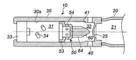
- FIG. 1 is a partial axial sectional view of a gas generator of the present invention.
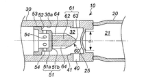
- FIG. 2 is a partially enlarged view of FIG.
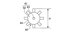
- FIG. 3 is a front view of the breaking means used in FIGS.
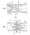
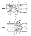
- FIG. 4 is a partial cross-sectional view for explaining changes before and after the operation of the gas generator of FIGS. 1 and 2.
- FIG. 5 is a partial cross-sectional view in the axial direction of a gas generator according to another embodiment.
- FIG. 6 is a partial cross-sectional view for explaining changes before and after the operation of the gas generator of FIG.
- the gas generator of 2005/0062272 has a structure in which combustion gas is generated and then discharged, and pressurized gas is discharged after a delay.
- US-A No. In 2005/0062272, the gas necessary for driving the opener 90 is partially discharged from the housing, the gas treatment element 76 is required for heat exchange, the gas treatment element 76 is warmed, and the opener 90 Since it is necessary to destroy the rupturable plate 84 with the needle portion 94, there is a problem that the amount of the gas generating agent increases and it is difficult to reduce the size of the gas generator. In particular, heat exchange with the gas treatment element 76 is necessary for the decomposition of the pressurized gas N 2 O. In 2005/0062272, the gas treatment element 76 is essential.
- the present invention provides a gas generator that can be miniaturized because combustion gas and pressurized gas are discharged in parallel through a narrow space.
- the gas generator of the present invention moves while the partition wall reduces the volume of the gas inflow chamber into which the combustion gas and the pressurized gas flow. For this reason, even when the combustion gas and the pressurized gas are discharged substantially simultaneously, the high-temperature combustion gas and the low-temperature pressurized gas pass through the gas inflow chamber whose volume has been reduced, and are combined into the gas. It is discharged from the outlet. For this reason, the temperature of the exhaust gas is not greatly reduced without adversely affecting the inflation of the airbag without using a coolant for exchanging heat of the gas, and the temperature of the exhaust gas is not adversely affected. There is nothing.
- the partition wall only needs to be able to separate the gas generation chamber and the gas inflow chamber and form the communication hole.
- a partition what consists of a disk, what has an annular wall extended in one direction from the circular bottom face and the said bottom periphery can be used. By adjusting the length of the annular wall, it is possible to make a dish having a shallow bottom or a cup having a deep bottom.
- the partition wall is made of a disk, a communication hole is formed through the disk in the thickness direction, and the peripheral surface of the disk is in contact with the inner peripheral wall surface of the cylindrical gas generation chamber housing. Yes.
- the partition wall has a circular bottom surface and an annular wall extending in one direction from the periphery of the bottom surface, a communication hole is formed through the circular bottom surface in the thickness direction, and the annular wall is a cylindrical gas. It is in contact with the inner peripheral wall surface of the generation chamber housing. In this case, the annular wall functions as a guide when the partition moves.
- the volume of the gas inflow chamber can be adjusted so that it reaches a predetermined volume when the stepped portion or convex portion formed in the partition wall and the gas generating chamber hits, so that the discharge of the combustion gas and the pressurized gas is hindered. It will never be done.
- the step portion is preferably an annular step portion formed by changing the inner diameter of the inner wall surface of the gas inflow chamber (gas generation chamber housing).
- the convex portion is preferably an annular convex portion protruding inward from the inner wall surface of the gas inflow chamber (gas generation chamber housing) or a plurality of independent convex portions.
- the breaking means formed on the partition wall has an outer diameter smaller than the inner diameter of the opening closed by the closing member, and a gap generated by the difference in outer diameter between the opening and the means is a pressurized gas. It becomes the discharge route.
- the breaking means formed on the partition wall only needs to be made of a material and a shape that can break and open the closing member, and may be formed integrally with the partition wall or fixed to the partition wall by means such as welding. May be good.
- the closure member should just be arrange
- a preferred embodiment 1 of the present invention is as follows.
- the partition is It has a cup part, a flange part formed in the opening part of the cup part, and an annular wall part suspended from the flange part,
- the bottom surface of the cup portion is directly opposed to the closing member at a distance, and the circumferential surface of the cup portion is directly opposed to the inner peripheral wall surface of the cylindrical gas generation chamber housing.
- the peripheral surface of the cup portion has a communication hole for communicating the gas generation chamber and the gas inflow chamber,
- the outer peripheral surface of the annular wall portion is in contact with the inner peripheral wall surface of the cylindrical gas generation chamber housing so as to be movable in the axial direction,
- the destruction means is Having an outer diameter smaller than the inner diameter of the opening closed by the closing member; It is formed on the bottom surface of the cup part so as to face the closing member with a gap therebetween,
- the flange portion of the partition stops by hitting a convex portion formed in the gas inflow chamber, Opening the pressurized gas discharge path from the pressurized gas chamber to the gas inflow chamber by the destruction means destroying the closing member;
- the combustion gas generated from the gas generating chamber and the pressurized gas flowing out from the pressurized gas chamber are discharged from the gas outlet through the gas inflow chamber having the reduced volume. It is a gas generator.
- the preferred embodiment 1 of the present invention embodies the differences that differ from the present invention only in the structure of the partition walls.
- the partition wall has an annular wall portion suspended from the flange portion, and the outer peripheral surface of the annular wall portion contacts the inner peripheral wall surface of the cylindrical gas generation chamber housing so as to be movable in the axial direction. It is touched. When the partition wall is moved, the annular wall portion functions as a guide portion.
- a preferred embodiment 2 of the present invention is as follows.
- the breaking means fixed to the partition wall has a plurality of grooves formed continuously in the length direction on the peripheral surface of the columnar molded body, According to the present invention or the present invention, the plurality of grooves serve as gas discharge paths from the pressurized gas chamber to the gas inflow chamber when the breaking means is opened by colliding with the blocking member and breaking through.
- the breaking means has an outer diameter smaller than the inner diameter of the opening closed by the closing member, and has a plurality of grooves formed in the length direction on the peripheral surface of the columnar molded body.
- the columnar molded body is a cylinder, a prism, or the like, and those having a sharp tip, a spherical shape, or a flat surface can be used.
- the columnar molded body has a plurality of grooves formed in the length direction on the peripheral surface. The depth and number of the grooves are adjusted in consideration of the strength of the columnar molded body that serves as a breaking means for the closing member.
- Preferred embodiment 3 of the present invention is as follows:
- the destruction means fixed to the partition wall is a hollow columnar shaped body,
- the hollow columnar molded body has a first opening formed on the tip end side and a second opening formed on the partition wall side, A gas discharge path from the pressurized gas chamber to the gas inflow chamber when the first opening, the hollow portion, and the second opening are opened by colliding the breaking means against the closing member and breaking through;
- the breaking means has an outer diameter smaller than the inner diameter of the opening closed by the closing member, has a hollow inside, and has a first opening and a second opening formed at different positions. It is what you are doing.
- the columnar molded body is a cylinder, a prism, or the like, and those having a sharp tip, a spherical shape, or a flat surface can be used.
- the hollow part of the columnar molded body communicates with the outside through the first opening and the second opening.
- the size of the hollow portion of the columnar molded body is adjusted in consideration of the strength of the columnar molded body serving as a means for breaking the blocking member.
- the breaking means (columnar molded body having a hollow portion) breaks through the blocking member, the pressurized gas in the pressurized gas bottle enters the hollow portion from the first opening of the columnar molded body, and further from the second opening. Go out and enter the gas inflow chamber.
- a preferred embodiment 4 of the present invention is as follows.
- the tip of the cylinder or prism is arrowhead-shaped, the tip of the cylinder or prism has a surface cut obliquely in the length direction, or from a cone or pyramid Can be used.
- the gas generator of the present invention uses both combustion gas and pressurized gas as gas sources, and a container for housing each of them is required. Since the gas is discharged in parallel through a narrow space, a part for adjusting the gas temperature is unnecessary, and therefore, the size can be reduced as compared with the conventional product.
- the gas generator 10 includes a pressurized gas bottle 20 filled with a pressurized gas and a cylindrical gas generation chamber housing 30. These are made of metals such as iron and stainless steel.
- the interior of the pressurized gas bottle 20 is a pressurized gas chamber 21 and is filled with a known gas such as argon or helium at a high pressure.
- a space between the pressurized gas bottle 20 and the gas generation chamber housing 30 is closed by a closing member 25.
- the blocking member 25 may have a weakened portion (groove or the like) formed on the surface of the pressurized gas bottle 20 side.
- the closing member 25 is fixed to one end opening of the gas generation chamber housing 30, but the closing member 25 may be fixed to the opening of the pressurized gas bottle 20.
- the closing member 25 is made of a metal disk such as iron or stainless steel.
- the closing member 25 receives a pressure in the pressurized gas chamber 21 and is deformed into a bowl shape on the gas generation chamber housing 30 side. is doing.
- the gas generation chamber housing 30 has a gas generation chamber 31 and a gas inflow chamber 32, which are separated by a partition wall 50 having a breaking means 60.
- An electric igniter 33 used in a known gas generator is fixed to the opening of the gas generation chamber 31 (the other end side opening of the gas generation chamber housing 30).
- the gas generating chamber 31 is filled with a gas generating agent 34 used in a known gas generator.
- the partition wall 50 includes a cup part 51, a flange part 52 formed in the opening of the cup part 51, and an annular wall part 53 that is suspended from the flange part 52.
- the peripheral surface 51 a of the cup portion 51 has a plurality of communication holes 54 and is opposed to the inner peripheral wall surface 30 a of the cylindrical gas generation chamber housing 30 with a gap.
- the size of the communication hole 54 is a size that prevents the gas generating agent 34 from passing through.
- the outer peripheral surface of the annular wall portion 53 is in contact with the inner peripheral wall surface 30a of the cylindrical gas generation chamber housing so as to be movable in the axial direction.
- the destruction means 60 has an outer diameter (d2) smaller than the inner diameter (d1) of the opening closed by the closing member 25, and d2 is larger than the outer diameter of the bottom surface 51b (circumferential surface 51a). It is small and protrudes toward the closing member 25 from the bottom surface 51b.
- the breaking means 60 is fixed to the bottom surface 51b of the cup portion 51 so as to face the closing member 25 at a distance.
- the destruction means 60 is composed of a columnar shaped body 61.
- the columnar molded body 61 has a plurality of grooves 64 formed continuously in the length direction on the peripheral surface 62, and the tip 63 is pointed in a conical shape.
- the plurality of grooves 64 serve as gas discharge paths from the pressurized gas bottle 20 (the pressurized gas chamber 21) to the gas inflow chamber 32 when the breaking means 60 is opened by colliding with the closing member 25 and breaking through. It is.
- the gas inflow chamber 32 is a space sandwiched between the closing member 25 and the partition wall 50, and the combustion gas that has flowed out of the gas generation chamber 31 and the pressurized gas bottle 20 (pressurized gas chamber 21). It is a space into which pressurized gas flows.
- a plurality of gas discharge ports 40 are formed in the gas generation chamber housing 30 facing the gas inflow chamber 32, and are closed from the inside with aluminum tape or the like before operation.
- An annular step 41 formed by reducing the inner diameter of the gas generation chamber housing 30 is formed in the gas inflow chamber 32 on the gas generation chamber 31 side from the position where the gas discharge port 40 is formed. Yes.
- the gas generator 10 When the electric igniter 33 is activated, the gas generating agent 34 in the gas generating chamber 31 is ignited and burned to generate combustion gas.
- the partition wall 50 moves in the axial direction (the closing member 25 side) while reducing the volume of the gas inflow chamber 32, and the flange portion 52 hits the annular stepped portion 41. The movement is stopped.
- the breaking means 60 breaks and opens the closing member 25, and the discharge path of the pressurized gas in the pressurized gas chamber 21 is opened.
- the front end side of the groove 64 of the breaking member 60 is located in the pressurized gas chamber 21, and the opposite end is located in the gas inflow chamber 32.
- the pressurized gas flows out of the pressurized gas chamber 21 through the gas discharge path formed by the groove 64 of the breaking means 60 and the cleaved blocking member 25, and collides with the cup portion bottom surface 51 b of the partition wall 50.
- the gas is discharged from the gas discharge port 40 through the gas inflow chamber 32 having a reduced volume.
- the combustion gas in the gas generation chamber 31 flows out from the communication hole 54 of the partition wall 50 and is discharged from the gas discharge port 40 through the gas inflow chamber 32 whose volume is reduced.
- the gas generator 10 is discharged from the gas discharge port 40 after passing through the gas inflow chamber 32 in which the volume is reduced by combining the high-temperature combustion gas and the low-temperature pressurized gas.
- the temperature of the gas is sufficient to inflate the airbag and can be maintained at a temperature that does not adversely affect people.
- US-A No. Since the gas treatment element 76 in the 2005/0062272 gas generator is not required, a large space for arranging the gas treatment element 76 is not required, and the amount of combustion gas required to warm the gas treatment element 76 is also not required. Since the amount of the gas generating agent can be reduced, the gas generator can be reduced in size.
- the partition wall 50 is located closer to the gas generation chamber 31 than the gas discharge port 40, the partition wall 50 can be efficiently moved by the combustion gas generated in the gas generation chamber 31. For this reason, US-A No. As in 2005/0062272, a part of the combustion gas is not discharged from the discharge port 74 before moving the opener 90, and can be operated reliably.
- the gas generator 100 in FIG. 5 differs from the gas generator 10 in FIGS. 1 and 2 only in the destruction means 160 fixed to the partition wall 50, and the others. The same.
- the destruction means 160 has an outer diameter (an outer diameter having the same dimension as d2 in FIG. 3) smaller than the inner diameter (d1) of the opening portion closed by the closing member 25.
- the breaking means 160 is fixed to the bottom surface 51b of the cup portion 51 so as to face the closing member 25 at a distance.
- the destruction means 160 consists of a hollow columnar molded body 161, and the tip 163 has a truncated cone shape.
- the hollow columnar molded body 161 has a first opening 165 formed on the peripheral surface 162 on the tip end portion 163 side and a second opening 166 formed on the peripheral surface 162 on the bottom surface 51b side. Is a hollow portion 164.
- the combination of the first opening portion 165, the hollow portion 164, and the second opening portion 166 is a combination of the pressurized gas bottle 20 (the pressurized gas chamber 21) when the breaking means 160 is opened by colliding with the closing member 25 and breaking through. This is a gas discharge path from the gas to the gas inflow chamber 32.
- the gas generator 100 When the electric igniter 33 is activated, the gas generating agent 34 in the gas generating chamber 31 is ignited and burned to generate combustion gas.
- the partition wall 50 moves in the axial direction while reducing the volume of the gas inflow chamber 32, and the movement is stopped when the flange portion 52 hits the annular step portion 41.
- the breaking means 160 breaks and opens the closing member 25, and the gas discharge path for the pressurized gas in the pressurized gas chamber 21 is opened.
- the first opening 165 of the breaking member 160 is located in the pressurized gas chamber 21, and the second opening 166 is located in the gas inflow chamber 32. Then, after the pressurized gas enters the hollow portion 164 from the first opening 165 of the breaking means 160 and enters the gas inflow chamber 32 through which the volume is reduced from the hollow portion 164 through the second opening 166, It is discharged from the gas discharge port 40. On the other hand, the combustion gas in the gas generation chamber 31 flows out from the communication hole 54 of the partition wall 50 and is discharged from the gas discharge port 40 through the gas inflow chamber 32 whose volume is reduced.
- the gas generator 100 is discharged from the gas discharge port 40 after passing through the gas inflow chamber 32 whose volume is reduced together with the high-temperature combustion gas and the low-temperature pressurized gas.
- the temperature of the gas is sufficient to inflate the airbag and can be maintained at a temperature that does not adversely affect people.
- US-A No. Since the gas treatment element 76 in the 2005/0062272 gas generator is not required, a large space for placing it is not required. Further, since the amount of combustion gas necessary for warming the gas treatment element 76 is not required, the amount of gas generating agent can be reduced. Therefore, the gas generator can be reduced in size.
- the partition wall 50 is located closer to the gas generation chamber 31 than the gas discharge port 40, the partition wall 50 can be efficiently moved by the combustion gas generated in the gas generation chamber 31. 5 and FIG. 6, the tip of the cylinder is cut obliquely as the breaking means 160, the opening on the tip side is the first opening, the inside of the cylinder is the hollow, and the bottom surface What formed the 2nd opening part in the 51b side can also be used.
Landscapes
- Engineering & Computer Science (AREA)
- Mechanical Engineering (AREA)
- Physics & Mathematics (AREA)
- Fluid Mechanics (AREA)
- General Engineering & Computer Science (AREA)
- Air Bags (AREA)
Abstract
Description
ガス源としてガス発生剤の燃焼ガスと、アルゴンやヘリウムなどのガスを利用したガス発生器が使用されている(US-A No. 2005/0062272)。
ボトル14の開口部は、バーストディスク84で閉塞され、それを開裂させるオープナー90が配置されている。
作動時には、先にガス発生剤54からの燃焼ガスが発生し、ガストリートメント要素76を温めたあとでガス排出口74から排出され、一部の燃焼ガスはオープナー90を軸方向に移動させる。
その後、オープナー90のニードル部94で破裂板84が開裂されたあと、加圧ガスがオープナー90の中央部に形成された通路を通ってガス排出口74から排出される。この過程において、温められたガストリートメント要素76を加圧ガスが通ることによって、加圧ガス成分であるN2Oの分解が促進されるようになっている。
本発明は、
加圧ガスが充填された加圧ガス室を形成する加圧ガスボトルと筒状のガス発生室ハウジングから外殻容器が形成されており、
前記加圧ガスボトルと前記ガス発生室ハウジングの間が閉塞部材で閉塞されており、
前記ガス発生室ハウジングが、
点火手段とガス発生剤が収容されたガス発生室を有し、
前記加圧ガス室と前記ガス発生室との間に、前記ガス発生室から流出した燃焼ガスと前記加圧ガス室から流出した加圧ガスが流入するガス流入室を有しており、
前記ガス発生室と前記ガス流入室が、前記閉塞部材を破壊するための破壊手段を備えた隔壁で分離されており、
前記ガス流入室が、ガス排出口を有し、さらに前記ガス排出口が形成された位置よりも前記ガス発生室側において段差部または凸部を有しており、
前記隔壁が、
前記ガス発生室と前記ガス流入室を連通する連通孔を有しており、
前記隔壁の外周縁面が、軸方向に移動可能になるように前記外殻容器の内周壁面に当接され、
前記閉塞部材と間隔をおいて正対されているものであり、
前記破壊手段が、
前記閉塞部材で閉塞された開口部の内径よりも小さな外径を有しており、
前記閉塞部材と間隔をおいて正対するようにして前記隔壁に形成されているものであり、
作動時において、
前記破壊手段を備えた隔壁が、前記ガス流入室の容積を減少させながら軸方向に移動した後で、前記隔壁の外周面が前記ガス流入室に形成された段差部または凸部に当たることで停止すると共に、前記破壊手段が前記閉塞部材を破壊することで前記加圧ガス室から前記ガス流入室への加圧ガス排出経路を開放し、
前記ガス発生室から発生した燃焼ガスと前記加圧ガス室から流出した加圧ガスが、前記容積が減少されたガス流入室を通ってガス排出口から排出されるものである、ガス発生器を提供する。
US-A No. 2005/0062272のガス発生器は、構造上、燃焼ガスを先に発生させた後で排出し、遅れて加圧ガスを排出させるようになっている。
US-A No. 2005/0062272では、オープナー90の駆動に必要なガスが一部ハウジング外に排出されること、熱交換のためにガストリートメント要素76が必要であること、ガストリートメント要素76を温め、かつオープナー90のニードル部94で破裂板84を破壊する必要があることから、ガス発生剤量が多くなり、ガス発生器の小型化が困難であるという問題がある。
特にガストリートメント要素76との熱交換は、加圧ガスであるN2Oの分解に必要であり、US-A No. 2005/0062272ではガストリートメント要素76が必須となっている。
このため、燃焼ガスと加圧ガスを実質的に同時に排出させたときであっても、高温の燃焼ガスと低温の加圧ガスは容積が減少されたガス流入室を通り、一緒になってガス排出口から排出される。このため、ガスを熱交換させるクーラントを使用せずとも排出ガスの温度が大きく低下してエアバッグの膨張に悪影響を与えることはなく、また排出ガスの温度が高くなることで人に悪影響を与えることもない。
このような隔壁としては、円板からなるもの、円形底面と前記底面周縁から一方向に伸ばされた環状壁を有するものなどを使用することができる。前記環状壁の長さを調整することで、底の浅い皿状のものや、底の深いカップ状のものにすることができる。
隔壁が円板からなるものの場合は、円板を厚さ方向に貫通して連通孔が形成されており、円板の周面が筒状のガス発生室ハウジングの内周壁面に当接されている。
隔壁が円形底面と前記底面周縁から一方向に伸ばされた環状壁を有するものの場合には、前記円形底面を厚さ方向に貫通して連通孔が形成されており、環状壁が筒状のガス発生室ハウジングの内周壁面に当接されている。この場合環状壁は隔壁が移動するときのガイドとして機能する。
段差部は、ガス流入室(ガス発生室ハウジング)の内壁面の内径を変化させることで形成された環状の段差部であることが好ましい。
凸部は、ガス流入室(ガス発生室ハウジング)の内壁面から内側に突き出された環状凸部または独立した複数の凸部であることが好ましい。
隔壁に形成された破壊手段は、閉塞部材を破壊して開口できるような材質および形状からなるものであればよく、隔壁と一体成形されたものでもよいし、隔壁に溶接などの手段で固定されたものでもよい。なお、閉塞部材は加圧ガスボトルとガス発生室ハウジングの間で配置されていればよく、固定箇所や方法は限定されない。
例えば、ステンレスや鉄からなるもので、円柱、角柱のようなもののほか、先端部が尖っているもの、球状のもの、平坦面であるものを使用することができる。
前記隔壁が、
カップ部と、前記カップ部の開口部に形成されたフランジ部と、前記フランジ部から垂設された環状壁部を有しているものであり、
前記カップ部の底面が前記閉塞部材と間隔をおいて正対され、前記カップ部の周面が前記筒状のガス発生室ハウジングの内周壁面と間隔をおいて正対されているものであり、
前記カップ部の周面が、前記ガス発生室と前記ガス流入室を連通するための連通孔を有しており、
前記環状壁部の外周面が、軸方向に移動可能になるように前記筒状のガス発生室ハウジングの内周壁面に当接されているものであり、
前記破壊手段が、
前記閉塞部材で閉塞された開口部の内径よりも小さな外径を有しており、
前記閉塞部材と間隔をおいて正対するようにして前記カップ部の底面に形成されているものであり、
作動時において、
前記破壊手段を備えた隔壁が、前記ガス流入室の容積を減少させながら軸方向に移動した後で、前記隔壁のフランジ部が前記ガス流入室に形成された凸部に当たることで停止すると共に、前記破壊手段が前記閉塞部材を破壊することで前記加圧ガス室から前記ガス流入室への加圧ガス排出経路を開放し、
前記ガス発生室から発生した燃焼ガスと前記加圧ガス室から流出した加圧ガスが、前記容積が減少されたガス流入室を通ってガス排出口から排出されるものである、上記本発明のガス発生器である。
隔壁は、フランジ部から垂設された環状壁部を有しており、環状壁部の外周面が、軸方向に移動可能になるように前記筒状のガス発生室ハウジングの内周壁面に当接されている。そして隔壁移動の際に環状壁部がガイド部として機能する。
本発明のガス発生器では、燃焼ガスは隔壁カップ部の周面に形成された連通孔を通って半径方向に流出した後で、ガス流入室を通ってガス排出口から排出され、加圧ガスは、閉塞部材の開口部を通った後で隔壁カップ部の底面部にぶつかって半径方向に向きを変え、ガス流入室を通ってガス排出口から排出される。
このため、US-A No. 2005/0062272のガス発生器のように、燃焼ガスと加圧ガス互いに逆方向から衝突するようなことはない。
前記隔壁に固定された前記破壊手段が、柱状成形体の周面において長さ方向に連続して形成された複数の溝を有しているものであり、
前記複数の溝が、前記破壊手段を前記閉塞部材に衝突させて突き破ることで開口させたとき、前記加圧ガス室から前記ガス流入室へのガス排出経路となる、上記本発明または本発明の好ましい態様1のガス発生器である。
柱状成形体は、円柱、角柱などであり、先端部が尖っているもの、球状のもの、平坦面であるものを使用することができる。
柱状成形体は、周面に長さ方向に形成された複数の溝を有している。
溝の深さと本数は、閉塞部材の破壊手段となる柱状成形体の強度を考慮して調整される。
破壊手段(柱状成形体)が閉塞部材を突き破ったとき、加圧ガスボトル内の加圧ガスは、周面にある溝を通ってガス流入室に入る。
前記隔壁に固定された前記破壊手段が中空の柱状成形体からなるものであり、
前記中空の柱状成形体が、先端部側に形成された第1開口部と前記隔壁側に形成された第2開口部を有しており、
前記第1開口部、中空部および第2開口部が、前記破壊手段を前記閉塞部材に衝突させて突き破ることで開口させたとき、前記加圧ガス室から前記ガス流入室へのガス排出経路となる、上記本発明または本発明の好ましい態様1のガス発生器である。
柱状成形体は、円柱、角柱などであり、先端部が尖っているもの、球状のもの、平坦面であるものを使用することができる。
柱状成形体の中空部は、第1開口部と第2開口部により外部と連通されている。
柱状成形体の中空部の大きさは、閉塞部材の破壊手段となる柱状成形体の強度を考慮して調整される。
破壊手段(中空部のある柱状成形体)が閉塞部材を突き破ったとき、加圧ガスボトル内の加圧ガスは、柱状成形体の第1開口部から中空部に入り、さらに第2開口部から外に出て、ガス流入室に入る。
前記破壊手段が、前記閉塞部材に面した先端部が尖っているものである、上記本発明、本発明の好ましい態様1~3のいずれか1つのガス発生器を提供する。
(1)図1~図3のガス発生器
ガス発生器10は、加圧ガスが充填された加圧ガスボトル20と筒状のガス発生室ハウジング30を有している。これらは鉄、ステンレスなどの金属からなるものである。
加圧ガスボトル20の内部は加圧ガス室21となっており、アルゴン、ヘリウムなどの公知のガスが高圧充填されている。
加圧ガスボトル20とガス発生室ハウジング30の間は、閉塞部材25で閉塞されている。閉塞部材25は、加圧ガスボトル20側の面に脆弱部(溝など)が形成されていてもよい。
図1のガス発生器10では、ガス発生室ハウジング30の一端開口部に閉塞部材25が固定されているが、加圧ガスボトル20の開口部に閉塞部材25が固定されていてもよい。
閉塞部材25は、鉄、ステンレスなどの金属製円板からなるものであり、図1、図2では、加圧ガス室21内の圧力を受けて、ガス発生室ハウジング30側に椀状に変形している。
ガス発生室31の開口部(ガス発生室ハウジング30の他端側開口部)は、公知のガス発生器で使用している電気式点火器33が固定されている。
ガス発生室31の内部には、公知のガス発生器で使用しているガス発生剤34が充填されている。
カップ部の51の周面51aは、複数の連通孔54を有しており、筒状のガス発生室ハウジング30の内周壁面30aと間隔をおいて正対されている。連通孔54の大きさは、ガス発生剤34が通り抜けない大きさである。
環状壁部53の外周面は、軸方向に移動可能になるように筒状のガス発生室ハウジングの内周壁面30aに当接されている。
破壊手段60は、閉塞部材25と間隔をおいて正対するようにしてカップ部51の底面51bに固定されている。
破壊手段60は、柱状成形体61からなるものである。
柱状成形体61は、周面62において長さ方向に連続して形成された複数の溝64を有しており、先端部63は円錐状に尖っている。
複数の溝64は、破壊手段60を閉塞部材25に衝突させて突き破ることで開口させたとき、加圧ガスボトル20(加圧ガス室21)からガス流入室32へのガス排出経路となるものである。
ガス流入室32に面したガス発生室ハウジング30には、複数のガス排出口40が形成されており、作動前は、内側からアルミニウムテープなどで閉塞されている。
ガス流入室32内には、ガス排出口40が形成された位置よりもガス発生室31側において、ガス発生室ハウジング30の内径を小さくすることで形成された環状の段差部41が形成されている。
電気式点火器33が作動すると、ガス発生室31内のガス発生剤34が着火燃焼されて燃焼ガスが発生する。
ガス発生室31内の圧力上昇を受けて隔壁50は、ガス流入室32の容積を減少させながら軸方向(閉塞部材25側)に移動して、フランジ部52が環状の段差部41に当たることで移動が停止される。
この過程において、破壊手段60が閉塞部材25を突き破って開口させ、加圧ガス室21内の加圧ガスの排出経路が開放される。このとき、破壊部材60の溝64の先端側は加圧ガス室21内に位置し、反対側端部はガス流入室32内に位置している。
そして、加圧ガスは、破壊手段60の溝64と開裂した閉塞部材25とで形成されるガス排出経路を通って加圧ガス室21から流出され、隔壁50のカップ部底面51bに衝突して半径方向に向きを変えたあと、容積が減少されたガス流入室32を通って、ガス排出口40から排出される。
一方、ガス発生室31内の燃焼ガスは、隔壁50の連通孔54から流出され、容積が減少されたガス流入室32を通って、ガス排出口40から排出される。
このため、US-A No. 2005/0062272のガス発生器におけるガストリートメント要素76が不要になることから、それを配置するための大きな空間が不要になるほか、ガストリートメント要素76を温めるために必要な燃焼ガス量も不要になりガス発生剤量も減量できることから、ガス発生器を小型化することができる。
さらには隔壁50がガス排出口40よりもガス発生室31側に存在するため、ガス発生室31で発生した燃焼ガスにより効率よく隔壁50を移動させることができる。このため、US-A No. 2005/0062272のように燃焼ガスの一部がオープナー90を移動させる前に排出口74から排出されることがなく、確実に作動させることができる。
図5のガス発生器100は、図1、図2のガス発生器10とは、隔壁50に固定された破壊手段160が異なっているだけであり、その他は同じである。
破壊手段160は、閉塞部材25と間隔をおいて正対するようにしてカップ部51の底面51bに固定されている。
破壊手段160は、中空の柱状成形体161からなるものであり、先端部163は円錐台状になっている。
中空の柱状成形体161は、先端部163側の周面162に形成された第1開口部165と、底面51b側の周面162に形成された第2開口部166を有しており、内部は中空部164となっている。
電気式点火器33が作動すると、ガス発生室31内のガス発生剤34が着火燃焼されて燃焼ガスが発生する。
ガス発生室31内の圧力上昇を受けて隔壁50は、ガス流入室32の容積を減少させながら軸方向に移動して、フランジ部52が環状の段差部41に当たることで移動が停止される。
この隔壁の移動の過程において、破壊手段160が閉塞部材25を突き破って開口させ、加圧ガス室21内の加圧ガスのガス排出経路が開放される。このとき、破壊部材160の第1開口部165は加圧ガス室21内に位置し、第2開口部166はガス流入室32内に位置している。
そして、加圧ガスは、破壊手段160の第1開口部165から中空部164内に入り、中空部164から第2開口部166を通って容積が減少されたガス流入室32に入ったあと、ガス排出口40から排出される。
一方、ガス発生室31内の燃焼ガスは、隔壁50の連通孔54から流出され、容積が減少されたガス流入室32を通って、ガス排出口40から排出される。
このため、US-A No. 2005/0062272のガス発生器におけるガストリートメント要素76が不要になることから、それを配置するための大きな空間が不要になる。またガストリートメント要素76を温めるために必要な燃焼ガス量も不要になることからガス発生剤量も減量できる。そのためガス発生器を小型化することができる。
さらには隔壁50がガス排出口40よりもガス発生室31側に存在するため、ガス発生室31で発生した燃焼ガスにより効率よく隔壁50を移動させることができる。
なお、図5、図6の実施例では、破壊手段160として筒の先端部を斜めに切断したものであり、先端部側の開口部を第1開口部とし、筒内部を中空部とし、底面51b側に第2開口部を形成したものを使用することもできる。
Claims (5)
- 加圧ガスが充填された加圧ガス室を形成する加圧ガスボトルと筒状のガス発生室ハウジングから外殻容器が形成されており、
前記加圧ガスボトルと前記ガス発生室ハウジングの間が閉塞部材で閉塞されており、
前記ガス発生室ハウジングが、
点火手段とガス発生剤が収容されたガス発生室を有し、
前記加圧ガス室と前記ガス発生室との間に、前記ガス発生室から流出した燃焼ガスと前記加圧ガス室から流出した加圧ガスが流入するガス流入室を有しており、
前記ガス発生室と前記ガス流入室が、前記閉塞部材を破壊するための破壊手段を備えた隔壁で分離されており、
前記ガス流入室が、ガス排出口を有し、さらに前記ガス排出口が形成された位置よりも前記ガス発生室側において段差部または凸部を有しており、
前記隔壁が、
前記ガス発生室と前記ガス流入室を連通する連通孔を有しており、
前記隔壁の外周縁面が、軸方向に移動可能になるように前記外殻容器の内周壁面に当接され、
前記閉塞部材と間隔をおいて正対されているものであり、
前記破壊手段が、
前記閉塞部材で閉塞された開口部の内径よりも小さな外径を有しており、
前記閉塞部材と間隔をおいて正対するようにして前記隔壁に形成されているものであり、
作動時において、
前記破壊手段を備えた隔壁が、前記ガス流入室の容積を減少させながら軸方向に移動した後で、前記隔壁の外周面が前記ガス流入室に形成された段差部または凸部に当たることで停止すると共に、前記破壊手段が前記閉塞部材を破壊することで前記加圧ガス室から前記ガス流入室への加圧ガス排出経路を開放し、
前記ガス発生室から発生した燃焼ガスと前記加圧ガス室から流出した加圧ガスが、前記容積が減少されたガス流入室を通ってガス排出口から排出されるものである、ガス発生器。 - 前記隔壁が、
カップ部と、前記カップ部の開口部に形成されたフランジ部と、前記フランジ部から垂設された環状壁部を有しているものであり、
前記カップ部の底面が前記閉塞部材と間隔をおいて正対され、前記カップ部の周面が前記筒状のガス発生室ハウジングの内周壁面と間隔をおいて正対されているものであり、
前記カップ部の周面が、前記ガス発生室と前記ガス流入室を連通するための連通孔を有しており、
前記環状壁部の外周面が、軸方向に移動可能になるように前記筒状のガス発生室ハウジングの内周壁面に当接されているものであり、
前記破壊手段が、
前記閉塞部材で閉塞された開口部の内径よりも小さな外径を有しており、
前記閉塞部材と間隔をおいて正対するようにして前記カップ部の底面に形成されているものであり、
作動時において、
前記破壊手段を備えた隔壁が、前記ガス流入室の容積を減少させながら軸方向に移動した後で、前記隔壁のフランジ部が前記ガス流入室に形成された凸部に当たることで停止すると共に、前記破壊手段が前記閉塞部材を破壊することで前記加圧ガス室から前記ガス流入室への加圧ガス排出経路を開放し、
前記ガス発生室から発生した燃焼ガスと前記加圧ガス室から流出した加圧ガスが、前記容積が減少されたガス流入室を通ってガス排出口から排出されるものである、請求項1記載のガス発生器。 - 前記隔壁に固定された前記破壊手段が、柱状成形体の周面において長さ方向に連続して形成された複数の溝を有しているものであり、
前記複数の溝が、前記破壊手段を前記閉塞部材に衝突させて突き破ることで開口させたとき、前記加圧ガス室から前記ガス流入室へのガス排出経路となる、請求項1または2記載のガス発生器。 - 前記隔壁に固定された前記破壊手段が中空の柱状成形体からなるものであり、
前記中空の柱状成形体が、先端部側に形成された第1開口部と前記隔壁側に形成された第2開口部を有しており、
前記第1開口部、中空部および第2開口部が、前記破壊手段を前記閉塞部材に衝突させて突き破ることで開口させたとき、前記加圧ガス室から前記ガス流入室へのガス排出経路となる、請求項1または2記載のガス発生器。 - 前記破壊手段が、前記閉塞部材に面した先端部が尖っているものである、請求項1~4のいずれか1項に記載のガス発生器。
Priority Applications (4)
| Application Number | Priority Date | Filing Date | Title |
|---|---|---|---|
| US15/030,420 US9751492B2 (en) | 2013-11-13 | 2014-10-24 | Gas generator |
| KR1020167011585A KR20160085252A (ko) | 2013-11-13 | 2014-10-24 | 가스 발생기 |
| CN201480057636.8A CN105658485A (zh) | 2013-11-13 | 2014-10-24 | 气体发生器 |
| DE112014005171.3T DE112014005171T5 (de) | 2013-11-13 | 2014-10-24 | Gasgenerator |
Applications Claiming Priority (2)
| Application Number | Priority Date | Filing Date | Title |
|---|---|---|---|
| JP2013-234599 | 2013-11-13 | ||
| JP2013234599A JP6219136B2 (ja) | 2013-11-13 | 2013-11-13 | ガス発生器 |
Publications (1)
| Publication Number | Publication Date |
|---|---|
| WO2015072308A1 true WO2015072308A1 (ja) | 2015-05-21 |
Family
ID=53057248
Family Applications (1)
| Application Number | Title | Priority Date | Filing Date |
|---|---|---|---|
| PCT/JP2014/078294 Ceased WO2015072308A1 (ja) | 2013-11-13 | 2014-10-24 | ガス発生器 |
Country Status (6)
| Country | Link |
|---|---|
| US (1) | US9751492B2 (ja) |
| JP (1) | JP6219136B2 (ja) |
| KR (1) | KR20160085252A (ja) |
| CN (1) | CN105658485A (ja) |
| DE (1) | DE112014005171T5 (ja) |
| WO (1) | WO2015072308A1 (ja) |
Families Citing this family (14)
| Publication number | Priority date | Publication date | Assignee | Title |
|---|---|---|---|---|
| JP6312545B2 (ja) * | 2014-07-24 | 2018-04-18 | 日本化薬株式会社 | ガス発生器 |
| JP6312571B2 (ja) * | 2014-09-29 | 2018-04-18 | 株式会社ダイセル | ガス発生器 |
| GB201707283D0 (en) * | 2014-11-09 | 2017-06-21 | Hip Hope Tech Ltd | Air bag mechanism |
| JP2016222117A (ja) * | 2015-05-29 | 2016-12-28 | 株式会社ダイセル | ガス発生器 |
| DE202016001333U1 (de) * | 2016-02-12 | 2017-05-17 | Trw Airbag Systems Gmbh | Hybridgasgenerator, Gassackmodul und Fahrzeugsicherheitssystem |
| JP6813997B2 (ja) * | 2016-09-02 | 2021-01-13 | 株式会社ダイセル | エアバッグ装置を備えた小型飛行体 |
| DE102018121999B4 (de) * | 2018-09-10 | 2023-08-31 | Autoliv Development Ab | Pyrotechnische Straffvorrichtung für einen Sicherheitsgurt einer Sicherheitsgurteinrichtung mit einer Kraftbegrenzungseinrichtung |
| CN109664857B (zh) * | 2018-12-26 | 2023-12-15 | 宁波保税区艾尔希汽车有限公司 | 一种用于侧气囊的混合式气体发生器 |
| CN110440042A (zh) * | 2019-08-16 | 2019-11-12 | 中煤科工集团重庆研究院有限公司 | 一种快开阀及应用其制备的抑爆器 |
| JP7324112B2 (ja) * | 2019-10-08 | 2023-08-09 | 株式会社ダイセル | シートフレームインフレータおよびエアバッグ装置 |
| EP4442518A4 (en) * | 2021-11-30 | 2025-11-19 | Daicel Corp | GAS GENERATOR |
| JP7726139B2 (ja) | 2022-07-06 | 2025-08-20 | 豊田合成株式会社 | 着用エアバッグ装置 |
| CN115352393B (zh) * | 2022-08-30 | 2023-09-12 | 湖北航天化学技术研究所 | 混合式气体发生器 |
| CN116085509A (zh) * | 2023-01-19 | 2023-05-09 | 哲弗智能系统(上海)有限公司 | 分控阀及消防系统 |
Citations (3)
| Publication number | Priority date | Publication date | Assignee | Title |
|---|---|---|---|---|
| JPH0958394A (ja) * | 1995-08-29 | 1997-03-04 | Matsushita Electric Ind Co Ltd | エアバッグ装置用ガス発生装置 |
| JPH10250525A (ja) * | 1997-03-07 | 1998-09-22 | Matsushita Electric Ind Co Ltd | 安全システムまたは保護システムのためのガス発生装置 |
| JP2000354756A (ja) * | 1999-05-21 | 2000-12-26 | Livbag Snc | ハイブリッドガスジェネレータ |
Family Cites Families (7)
| Publication number | Priority date | Publication date | Assignee | Title |
|---|---|---|---|---|
| KR0155087B1 (ko) * | 1995-06-30 | 1998-10-15 | 배순훈 | 장착이 용이한 차량용 에어백 |
| CN100540513C (zh) * | 2001-11-30 | 2009-09-16 | 大赛璐化学工业株式会社 | 充气器和气囊系统 |
| CN1278889C (zh) * | 2001-12-14 | 2006-10-11 | 关键安全体系股份有限公司 | 充气机 |
| US6857657B2 (en) * | 2003-04-07 | 2005-02-22 | Key Safety Systems, Inc. | Inflator having a support member capable of sliding to open the pressure vessel |
| US7192052B2 (en) | 2003-09-24 | 2007-03-20 | Autoliv Asp, Inc. | Inflation assembly with extended filling capability |
| JP2006111257A (ja) * | 2004-09-17 | 2006-04-27 | Daicel Chem Ind Ltd | ガス発生器 |
| EP2471692B2 (en) * | 2009-05-11 | 2022-01-05 | Joyson Safety Systems Germany GmbH | Gas generator for inflating a gas bag of a vehicle occupant restraint system and method of inflating a gas bag |
-
2013
- 2013-11-13 JP JP2013234599A patent/JP6219136B2/ja active Active
-
2014
- 2014-10-24 US US15/030,420 patent/US9751492B2/en not_active Expired - Fee Related
- 2014-10-24 DE DE112014005171.3T patent/DE112014005171T5/de not_active Withdrawn
- 2014-10-24 WO PCT/JP2014/078294 patent/WO2015072308A1/ja not_active Ceased
- 2014-10-24 CN CN201480057636.8A patent/CN105658485A/zh active Pending
- 2014-10-24 KR KR1020167011585A patent/KR20160085252A/ko not_active Withdrawn
Patent Citations (3)
| Publication number | Priority date | Publication date | Assignee | Title |
|---|---|---|---|---|
| JPH0958394A (ja) * | 1995-08-29 | 1997-03-04 | Matsushita Electric Ind Co Ltd | エアバッグ装置用ガス発生装置 |
| JPH10250525A (ja) * | 1997-03-07 | 1998-09-22 | Matsushita Electric Ind Co Ltd | 安全システムまたは保護システムのためのガス発生装置 |
| JP2000354756A (ja) * | 1999-05-21 | 2000-12-26 | Livbag Snc | ハイブリッドガスジェネレータ |
Also Published As
| Publication number | Publication date |
|---|---|
| US20160264092A1 (en) | 2016-09-15 |
| JP6219136B2 (ja) | 2017-10-25 |
| JP2015093596A (ja) | 2015-05-18 |
| DE112014005171T5 (de) | 2016-07-21 |
| KR20160085252A (ko) | 2016-07-15 |
| CN105658485A (zh) | 2016-06-08 |
| US9751492B2 (en) | 2017-09-05 |
Similar Documents
| Publication | Publication Date | Title |
|---|---|---|
| JP6219136B2 (ja) | ガス発生器 | |
| US8870222B2 (en) | Gas generator | |
| US20170043743A1 (en) | Gas generator | |
| JP6908619B2 (ja) | ガス発生器 | |
| US9944250B2 (en) | Gas generator | |
| JP5181971B2 (ja) | ガス発生装置 | |
| JP2008265434A (ja) | 車両の人員拘束用ガス発生器 | |
| JP2012076608A (ja) | ガス発生器 | |
| US20160207493A1 (en) | Rupturable plate and inflator using same | |
| US9566938B2 (en) | Gas generator | |
| WO2016121422A1 (ja) | ガス発生器用の閉塞部材の支持構造とそれを使用したガス発生器 | |
| JP6710167B2 (ja) | ガス発生器 | |
| JP6312571B2 (ja) | ガス発生器 | |
| WO2016051998A1 (ja) | ガス発生器 |
Legal Events
| Date | Code | Title | Description |
|---|---|---|---|
| 121 | Ep: the epo has been informed by wipo that ep was designated in this application |
Ref document number: 14861266 Country of ref document: EP Kind code of ref document: A1 |
|
| WWE | Wipo information: entry into national phase |
Ref document number: 15030420 Country of ref document: US |
|
| ENP | Entry into the national phase |
Ref document number: 20167011585 Country of ref document: KR Kind code of ref document: A |
|
| WWE | Wipo information: entry into national phase |
Ref document number: 1120140051713 Country of ref document: DE Ref document number: 112014005171 Country of ref document: DE |
|
| 122 | Ep: pct application non-entry in european phase |
Ref document number: 14861266 Country of ref document: EP Kind code of ref document: A1 |