WO2015072286A1 - 移動体の駆動制御装置 - Google Patents
移動体の駆動制御装置 Download PDFInfo
- Publication number
- WO2015072286A1 WO2015072286A1 PCT/JP2014/077771 JP2014077771W WO2015072286A1 WO 2015072286 A1 WO2015072286 A1 WO 2015072286A1 JP 2014077771 W JP2014077771 W JP 2014077771W WO 2015072286 A1 WO2015072286 A1 WO 2015072286A1
- Authority
- WO
- WIPO (PCT)
- Prior art keywords
- vehicle
- target
- deceleration
- driver
- stop
- Prior art date
Links
- 230000001172 regenerating effect Effects 0.000 claims abstract description 53
- 230000008929 regeneration Effects 0.000 claims description 5
- 238000011069 regeneration method Methods 0.000 claims description 5
- 230000001133 acceleration Effects 0.000 description 9
- 238000000034 method Methods 0.000 description 9
- 239000003550 marker Substances 0.000 description 6
- 238000001514 detection method Methods 0.000 description 4
- 238000010586 diagram Methods 0.000 description 4
- 230000006870 function Effects 0.000 description 4
- 239000003086 colorant Substances 0.000 description 2
- 238000004891 communication Methods 0.000 description 2
- 230000000994 depressogenic effect Effects 0.000 description 2
- 241000282326 Felis catus Species 0.000 description 1
- 238000010276 construction Methods 0.000 description 1
- 230000000694 effects Effects 0.000 description 1
- 239000012530 fluid Substances 0.000 description 1
- 239000000446 fuel Substances 0.000 description 1
- 230000012447 hatching Effects 0.000 description 1
- 230000001360 synchronised effect Effects 0.000 description 1
Images


Classifications
-
- B—PERFORMING OPERATIONS; TRANSPORTING
- B60—VEHICLES IN GENERAL
- B60L—PROPULSION OF ELECTRICALLY-PROPELLED VEHICLES; SUPPLYING ELECTRIC POWER FOR AUXILIARY EQUIPMENT OF ELECTRICALLY-PROPELLED VEHICLES; ELECTRODYNAMIC BRAKE SYSTEMS FOR VEHICLES IN GENERAL; MAGNETIC SUSPENSION OR LEVITATION FOR VEHICLES; MONITORING OPERATING VARIABLES OF ELECTRICALLY-PROPELLED VEHICLES; ELECTRIC SAFETY DEVICES FOR ELECTRICALLY-PROPELLED VEHICLES
- B60L7/00—Electrodynamic brake systems for vehicles in general
- B60L7/24—Electrodynamic brake systems for vehicles in general with additional mechanical or electromagnetic braking
- B60L7/26—Controlling the braking effect
-
- B—PERFORMING OPERATIONS; TRANSPORTING
- B60—VEHICLES IN GENERAL
- B60K—ARRANGEMENT OR MOUNTING OF PROPULSION UNITS OR OF TRANSMISSIONS IN VEHICLES; ARRANGEMENT OR MOUNTING OF PLURAL DIVERSE PRIME-MOVERS IN VEHICLES; AUXILIARY DRIVES FOR VEHICLES; INSTRUMENTATION OR DASHBOARDS FOR VEHICLES; ARRANGEMENTS IN CONNECTION WITH COOLING, AIR INTAKE, GAS EXHAUST OR FUEL SUPPLY OF PROPULSION UNITS IN VEHICLES
- B60K6/00—Arrangement or mounting of plural diverse prime-movers for mutual or common propulsion, e.g. hybrid propulsion systems comprising electric motors and internal combustion engines ; Control systems therefor, i.e. systems controlling two or more prime movers, or controlling one of these prime movers and any of the transmission, drive or drive units Informative references: mechanical gearings with secondary electric drive F16H3/72; arrangements for handling mechanical energy structurally associated with the dynamo-electric machine H02K7/00; machines comprising structurally interrelated motor and generator parts H02K51/00; dynamo-electric machines not otherwise provided for in H02K see H02K99/00
- B60K6/20—Arrangement or mounting of plural diverse prime-movers for mutual or common propulsion, e.g. hybrid propulsion systems comprising electric motors and internal combustion engines ; Control systems therefor, i.e. systems controlling two or more prime movers, or controlling one of these prime movers and any of the transmission, drive or drive units Informative references: mechanical gearings with secondary electric drive F16H3/72; arrangements for handling mechanical energy structurally associated with the dynamo-electric machine H02K7/00; machines comprising structurally interrelated motor and generator parts H02K51/00; dynamo-electric machines not otherwise provided for in H02K see H02K99/00 the prime-movers consisting of electric motors and internal combustion engines, e.g. HEVs
- B60K6/50—Architecture of the driveline characterised by arrangement or kind of transmission units
- B60K6/52—Driving a plurality of drive axles, e.g. four-wheel drive
-
- B—PERFORMING OPERATIONS; TRANSPORTING
- B60—VEHICLES IN GENERAL
- B60L—PROPULSION OF ELECTRICALLY-PROPELLED VEHICLES; SUPPLYING ELECTRIC POWER FOR AUXILIARY EQUIPMENT OF ELECTRICALLY-PROPELLED VEHICLES; ELECTRODYNAMIC BRAKE SYSTEMS FOR VEHICLES IN GENERAL; MAGNETIC SUSPENSION OR LEVITATION FOR VEHICLES; MONITORING OPERATING VARIABLES OF ELECTRICALLY-PROPELLED VEHICLES; ELECTRIC SAFETY DEVICES FOR ELECTRICALLY-PROPELLED VEHICLES
- B60L15/00—Methods, circuits, or devices for controlling the traction-motor speed of electrically-propelled vehicles
- B60L15/20—Methods, circuits, or devices for controlling the traction-motor speed of electrically-propelled vehicles for control of the vehicle or its driving motor to achieve a desired performance, e.g. speed, torque, programmed variation of speed
- B60L15/2009—Methods, circuits, or devices for controlling the traction-motor speed of electrically-propelled vehicles for control of the vehicle or its driving motor to achieve a desired performance, e.g. speed, torque, programmed variation of speed for braking
-
- B—PERFORMING OPERATIONS; TRANSPORTING
- B60—VEHICLES IN GENERAL
- B60W—CONJOINT CONTROL OF VEHICLE SUB-UNITS OF DIFFERENT TYPE OR DIFFERENT FUNCTION; CONTROL SYSTEMS SPECIALLY ADAPTED FOR HYBRID VEHICLES; ROAD VEHICLE DRIVE CONTROL SYSTEMS FOR PURPOSES NOT RELATED TO THE CONTROL OF A PARTICULAR SUB-UNIT
- B60W10/00—Conjoint control of vehicle sub-units of different type or different function
- B60W10/04—Conjoint control of vehicle sub-units of different type or different function including control of propulsion units
- B60W10/08—Conjoint control of vehicle sub-units of different type or different function including control of propulsion units including control of electric propulsion units, e.g. motors or generators
-
- B—PERFORMING OPERATIONS; TRANSPORTING
- B60—VEHICLES IN GENERAL
- B60W—CONJOINT CONTROL OF VEHICLE SUB-UNITS OF DIFFERENT TYPE OR DIFFERENT FUNCTION; CONTROL SYSTEMS SPECIALLY ADAPTED FOR HYBRID VEHICLES; ROAD VEHICLE DRIVE CONTROL SYSTEMS FOR PURPOSES NOT RELATED TO THE CONTROL OF A PARTICULAR SUB-UNIT
- B60W10/00—Conjoint control of vehicle sub-units of different type or different function
- B60W10/18—Conjoint control of vehicle sub-units of different type or different function including control of braking systems
- B60W10/184—Conjoint control of vehicle sub-units of different type or different function including control of braking systems with wheel brakes
- B60W10/188—Conjoint control of vehicle sub-units of different type or different function including control of braking systems with wheel brakes hydraulic brakes
-
- B—PERFORMING OPERATIONS; TRANSPORTING
- B60—VEHICLES IN GENERAL
- B60W—CONJOINT CONTROL OF VEHICLE SUB-UNITS OF DIFFERENT TYPE OR DIFFERENT FUNCTION; CONTROL SYSTEMS SPECIALLY ADAPTED FOR HYBRID VEHICLES; ROAD VEHICLE DRIVE CONTROL SYSTEMS FOR PURPOSES NOT RELATED TO THE CONTROL OF A PARTICULAR SUB-UNIT
- B60W20/00—Control systems specially adapted for hybrid vehicles
-
- B—PERFORMING OPERATIONS; TRANSPORTING
- B60—VEHICLES IN GENERAL
- B60W—CONJOINT CONTROL OF VEHICLE SUB-UNITS OF DIFFERENT TYPE OR DIFFERENT FUNCTION; CONTROL SYSTEMS SPECIALLY ADAPTED FOR HYBRID VEHICLES; ROAD VEHICLE DRIVE CONTROL SYSTEMS FOR PURPOSES NOT RELATED TO THE CONTROL OF A PARTICULAR SUB-UNIT
- B60W30/00—Purposes of road vehicle drive control systems not related to the control of a particular sub-unit, e.g. of systems using conjoint control of vehicle sub-units
- B60W30/18—Propelling the vehicle
- B60W30/18009—Propelling the vehicle related to particular drive situations
- B60W30/18109—Braking
- B60W30/18127—Regenerative braking
-
- B—PERFORMING OPERATIONS; TRANSPORTING
- B60—VEHICLES IN GENERAL
- B60L—PROPULSION OF ELECTRICALLY-PROPELLED VEHICLES; SUPPLYING ELECTRIC POWER FOR AUXILIARY EQUIPMENT OF ELECTRICALLY-PROPELLED VEHICLES; ELECTRODYNAMIC BRAKE SYSTEMS FOR VEHICLES IN GENERAL; MAGNETIC SUSPENSION OR LEVITATION FOR VEHICLES; MONITORING OPERATING VARIABLES OF ELECTRICALLY-PROPELLED VEHICLES; ELECTRIC SAFETY DEVICES FOR ELECTRICALLY-PROPELLED VEHICLES
- B60L2240/00—Control parameters of input or output; Target parameters
- B60L2240/10—Vehicle control parameters
- B60L2240/12—Speed
-
- B—PERFORMING OPERATIONS; TRANSPORTING
- B60—VEHICLES IN GENERAL
- B60L—PROPULSION OF ELECTRICALLY-PROPELLED VEHICLES; SUPPLYING ELECTRIC POWER FOR AUXILIARY EQUIPMENT OF ELECTRICALLY-PROPELLED VEHICLES; ELECTRODYNAMIC BRAKE SYSTEMS FOR VEHICLES IN GENERAL; MAGNETIC SUSPENSION OR LEVITATION FOR VEHICLES; MONITORING OPERATING VARIABLES OF ELECTRICALLY-PROPELLED VEHICLES; ELECTRIC SAFETY DEVICES FOR ELECTRICALLY-PROPELLED VEHICLES
- B60L2240/00—Control parameters of input or output; Target parameters
- B60L2240/40—Drive Train control parameters
- B60L2240/42—Drive Train control parameters related to electric machines
- B60L2240/423—Torque
-
- B—PERFORMING OPERATIONS; TRANSPORTING
- B60—VEHICLES IN GENERAL
- B60L—PROPULSION OF ELECTRICALLY-PROPELLED VEHICLES; SUPPLYING ELECTRIC POWER FOR AUXILIARY EQUIPMENT OF ELECTRICALLY-PROPELLED VEHICLES; ELECTRODYNAMIC BRAKE SYSTEMS FOR VEHICLES IN GENERAL; MAGNETIC SUSPENSION OR LEVITATION FOR VEHICLES; MONITORING OPERATING VARIABLES OF ELECTRICALLY-PROPELLED VEHICLES; ELECTRIC SAFETY DEVICES FOR ELECTRICALLY-PROPELLED VEHICLES
- B60L2240/00—Control parameters of input or output; Target parameters
- B60L2240/80—Time limits
-
- B—PERFORMING OPERATIONS; TRANSPORTING
- B60—VEHICLES IN GENERAL
- B60L—PROPULSION OF ELECTRICALLY-PROPELLED VEHICLES; SUPPLYING ELECTRIC POWER FOR AUXILIARY EQUIPMENT OF ELECTRICALLY-PROPELLED VEHICLES; ELECTRODYNAMIC BRAKE SYSTEMS FOR VEHICLES IN GENERAL; MAGNETIC SUSPENSION OR LEVITATION FOR VEHICLES; MONITORING OPERATING VARIABLES OF ELECTRICALLY-PROPELLED VEHICLES; ELECTRIC SAFETY DEVICES FOR ELECTRICALLY-PROPELLED VEHICLES
- B60L2250/00—Driver interactions
- B60L2250/16—Driver interactions by display
-
- B—PERFORMING OPERATIONS; TRANSPORTING
- B60—VEHICLES IN GENERAL
- B60L—PROPULSION OF ELECTRICALLY-PROPELLED VEHICLES; SUPPLYING ELECTRIC POWER FOR AUXILIARY EQUIPMENT OF ELECTRICALLY-PROPELLED VEHICLES; ELECTRODYNAMIC BRAKE SYSTEMS FOR VEHICLES IN GENERAL; MAGNETIC SUSPENSION OR LEVITATION FOR VEHICLES; MONITORING OPERATING VARIABLES OF ELECTRICALLY-PROPELLED VEHICLES; ELECTRIC SAFETY DEVICES FOR ELECTRICALLY-PROPELLED VEHICLES
- B60L2250/00—Driver interactions
- B60L2250/26—Driver interactions by pedal actuation
-
- B—PERFORMING OPERATIONS; TRANSPORTING
- B60—VEHICLES IN GENERAL
- B60W—CONJOINT CONTROL OF VEHICLE SUB-UNITS OF DIFFERENT TYPE OR DIFFERENT FUNCTION; CONTROL SYSTEMS SPECIALLY ADAPTED FOR HYBRID VEHICLES; ROAD VEHICLE DRIVE CONTROL SYSTEMS FOR PURPOSES NOT RELATED TO THE CONTROL OF A PARTICULAR SUB-UNIT
- B60W2555/00—Input parameters relating to exterior conditions, not covered by groups B60W2552/00, B60W2554/00
- B60W2555/60—Traffic rules, e.g. speed limits or right of way
-
- B—PERFORMING OPERATIONS; TRANSPORTING
- B60—VEHICLES IN GENERAL
- B60W—CONJOINT CONTROL OF VEHICLE SUB-UNITS OF DIFFERENT TYPE OR DIFFERENT FUNCTION; CONTROL SYSTEMS SPECIALLY ADAPTED FOR HYBRID VEHICLES; ROAD VEHICLE DRIVE CONTROL SYSTEMS FOR PURPOSES NOT RELATED TO THE CONTROL OF A PARTICULAR SUB-UNIT
- B60W2754/00—Output or target parameters relating to objects
- B60W2754/10—Spatial relation or speed relative to objects
- B60W2754/30—Longitudinal distance
-
- Y—GENERAL TAGGING OF NEW TECHNOLOGICAL DEVELOPMENTS; GENERAL TAGGING OF CROSS-SECTIONAL TECHNOLOGIES SPANNING OVER SEVERAL SECTIONS OF THE IPC; TECHNICAL SUBJECTS COVERED BY FORMER USPC CROSS-REFERENCE ART COLLECTIONS [XRACs] AND DIGESTS
- Y02—TECHNOLOGIES OR APPLICATIONS FOR MITIGATION OR ADAPTATION AGAINST CLIMATE CHANGE
- Y02T—CLIMATE CHANGE MITIGATION TECHNOLOGIES RELATED TO TRANSPORTATION
- Y02T10/00—Road transport of goods or passengers
- Y02T10/60—Other road transportation technologies with climate change mitigation effect
- Y02T10/62—Hybrid vehicles
-
- Y—GENERAL TAGGING OF NEW TECHNOLOGICAL DEVELOPMENTS; GENERAL TAGGING OF CROSS-SECTIONAL TECHNOLOGIES SPANNING OVER SEVERAL SECTIONS OF THE IPC; TECHNICAL SUBJECTS COVERED BY FORMER USPC CROSS-REFERENCE ART COLLECTIONS [XRACs] AND DIGESTS
- Y02—TECHNOLOGIES OR APPLICATIONS FOR MITIGATION OR ADAPTATION AGAINST CLIMATE CHANGE
- Y02T—CLIMATE CHANGE MITIGATION TECHNOLOGIES RELATED TO TRANSPORTATION
- Y02T10/00—Road transport of goods or passengers
- Y02T10/60—Other road transportation technologies with climate change mitigation effect
- Y02T10/64—Electric machine technologies in electromobility
-
- Y—GENERAL TAGGING OF NEW TECHNOLOGICAL DEVELOPMENTS; GENERAL TAGGING OF CROSS-SECTIONAL TECHNOLOGIES SPANNING OVER SEVERAL SECTIONS OF THE IPC; TECHNICAL SUBJECTS COVERED BY FORMER USPC CROSS-REFERENCE ART COLLECTIONS [XRACs] AND DIGESTS
- Y02—TECHNOLOGIES OR APPLICATIONS FOR MITIGATION OR ADAPTATION AGAINST CLIMATE CHANGE
- Y02T—CLIMATE CHANGE MITIGATION TECHNOLOGIES RELATED TO TRANSPORTATION
- Y02T10/00—Road transport of goods or passengers
- Y02T10/60—Other road transportation technologies with climate change mitigation effect
- Y02T10/72—Electric energy management in electromobility
Definitions
- the present invention relates to a method for regenerative control of an electric vehicle using an external recognition sensor.
- Patent Document 1 a device that controls the regenerative braking force based on the shift position, vehicle speed, obstacles, and the like has been proposed.
- the target braking force is based on at least one of the vehicle speed immediately before that, the accelerator return speed, the road surface gradient, the vehicle weight, the relative positional relationship with the front obstacle, and the friction coefficient of the road surface.
- means for controlling the regenerative braking force based on the target braking force in an electric motor vehicle capable of generating a regenerative braking force equivalent to an engine braking force, it is possible to cope with fluctuations in vehicle running resistance by controlling the regenerative braking force, and prior to brake operation. It is possible to realize a vehicle that can generate a large engine braking effect in a scene that requires a large braking force.
- Patent Document 1 Although the target regenerative braking force is controlled, there is no description of what regenerative braking force is generated at the target stop position. In addition, there is no description as to whether the vehicle is decelerating only with the regenerative braking force in the travel section up to the target stop position or the friction braking force by the foot brake is used together. (Hereinafter, deceleration caused by regenerative braking force is called regenerative deceleration.) As a result, when the target stop position is determined, the regenerative braking force can be used to stop at the target stop position, or the regenerative braking force can be used to stop before the target stop position. There are various cases, such as when it is necessary to use power together, and this may cause the driver to feel uncomfortable.
- the friction braking force there are various cases, such as when it is necessary to use the vehicle together, which may cause the driver to feel uncomfortable.
- the target stop position can be recognized by the external environment recognition device and when the regenerative braking force changes due to the case where the target stop position cannot be recognized, there is a possibility that the driver may feel uncomfortable.
- the regenerative braking force is calculated from the target stop position of the vehicle, and the regenerative deceleration caused by the regenerative braking force is controlled so as not to stop at the target stop position or to prevent the target inter-vehicle distance from being secured. It is characterized by doing.
- the regenerative braking control device keeps the regenerative braking force at a size that cannot be stopped at the target stop position or at a size that cannot secure the target inter-vehicle distance, thereby encouraging the driver to operate the brake pedal, and reducing the driver himself. Adjusting the speed can reduce the driver's uncomfortable feeling.
- FIG. 1 shows the configuration of a vehicle equipped with a braking assistance device according to an embodiment of the present invention.
- the present embodiment will be described using a passenger vehicle, the present invention can be applied to any mobile body operated by a driver such as a commercial vehicle or a construction machine.
- the vehicle includes a steering angle sensor 2, a direction indicator lever 3, an accelerator pedal 24, an accelerator pedal operation amount sensor 4, a brake pedal 25, and a brake pedal operation amount sensor 5 as driver operation amount detection means.
- a signal corresponding to the operation amount of the operator is transmitted to the controller 1.
- the controller 1 is connected to the navigation device 6, and the set route, map information, own vehicle position on the map, direction of the own vehicle, surrounding road information (signal position, stop line position, lane) Width, number of lanes, lane curve information, lane marker width, number of lane markers, lane marker curve information, speed limit, distinction between car-only road and general road, presence / absence of branch road, etc.) from navigation device 6 .
- the navigation device 6 has a communication function with the outside of the vehicle, and can acquire information on the color of the traffic light, information on timing at which the color of the traffic light changes, information on the position of other vehicles that are not visible from the vehicle, and the like.
- the vehicle is provided with wheel speed sensors 7fL, 7fR, 7rL, 7rR, and a vehicle behavior sensor 8 on the front and rear of the vehicle as means for detecting the motion state of the vehicle. Transmit to.
- the vehicle behavior sensor 8 can detect longitudinal acceleration, lateral acceleration, and yaw rate.
- the vehicle is provided with a front camera 10f, a front radar 11f, a rear camera 10r, and a rear radar 11r as means for detecting the external environment around the own vehicle, and information such as lane markers and obstacles around the own vehicle is sent to the controller 1. To transmit.
- the front camera 10f has a function as an image acquisition unit that acquires an image around the host vehicle and a lane recognition unit that recognizes a lane based on a lane marker or a road surface boundary in the acquired image.
- the front camera 10f recognizes the position of the signal, the position of the stop line, the display of the signal color, whether to turn left or right, the lane marker such as the white line, and the road boundary such as the road shoulder, and the positional relationship with the own vehicle, the own lane or the adjacent lane
- the width between the lane markers, the width between the left and right road surface boundaries, and the type of the lane marker and the road surface boundary are output.
- the road information related to the lane marker and the road surface boundary includes information at a plurality of positions in front of the host vehicle. Furthermore, road information at a plurality of positions is also provided regarding the rear and side of the host vehicle.
- the types of lane markers include types such as lines, cat's eyes, and botsdots, line colors, line types (solid lines, broken lines, dotted lines, and hatching).
- the types of road boundary are road shoulder edges, gutters, curbs, guardrails, walls, banks, and the like.
- the front camera 10f recognizes obstacles such as other vehicles and pedestrians, and outputs the positional relationship and relative speed with the own vehicle.
- the front radar 11f recognizes obstacles such as other vehicles and pedestrians, and outputs the positional relationship and relative speed with the own vehicle.
- the front radar 11f has a feature that it can accurately recognize obstacles farther than the front camera 10f.
- the front camera 10f has a feature that the detection angle is wider than that of the front radar 11f and the type of obstacle can be discriminated.
- the vehicle is provided with an engine 21 and a motor 22, and the controller 1 makes a drive request to these drive devices based on the operation amount of the driver and the external environment.
- the engine 21 and the motor 22 are requested to accelerate, and when the vehicle needs deceleration, the motor 22 is requested to decelerate.
- the motor 22 is an AC synchronous motor device connected to, for example, a rear wheel.
- the motor 22 applies a braking force to the rear wheel and applies a regenerative braking force to the vehicle.
- the kinetic energy of the vehicle is stored as electric energy in a battery (not shown), and the electric energy is reused when the motor is driven.
- the vehicle is also provided with a friction braking device 23, which transmits the operating force applied by the driver to the brake pedal 25 to the wheels via brake fluid, brake pads, and brake rotor (not shown), thereby causing the friction braking force to act on the vehicle.
- the friction braking device 23 converts the kinetic energy of the vehicle into heat energy by the brake pad and the brake rotor, and releases it to the outside of the vehicle.
- the vehicle is provided with information providing means 26 for providing information to the driver, and provides support information by image display, sound, warning light, etc. according to the type of driving support.
- the information providing means 26 is, for example, a monitor device with a built-in speaker, and may be installed not only at one place but at a plurality of places. FIG.
- the road condition acquisition unit 51 receives the signal position, stop line position, signal color, right / left turn indication, lane position, lane curvature from at least one of the front camera 10f, the front radar 11f, and the navigation device 6. It is a calculation part which acquires information, such as the width of a lane, the number of lanes.
- the target stop position calculation unit 52 is based on information from the road state acquisition unit 51 (particularly, the position of the preceding vehicle and the position of the stop line) and the position where the vehicle should stop (hereinafter referred to as the target stop position) The distance to is calculated.
- the driver intention acquisition unit 53 is a calculation unit that acquires information related to the operation of the driver based on information from the accelerator pedal operation amount sensor 4, the brake pedal operation amount sensor 5, and a travel mode setting switch (not shown).
- the deceleration intention determination unit 54 is a calculation unit that determines whether the driver has an intention to decelerate based on information from the driver intention acquisition unit 53. For example, when the foot is away from the accelerator pedal, it is determined that there is an intention to decelerate.
- the target speed and target acceleration calculation unit 55 calculates the target speed at the target stop position and the deceleration until the vehicle stops at the target stop position based on the distance to the target stop position, the driver's intention to decelerate, and the motion state of the vehicle. Calculate.
- the vehicle motion control unit 56 controls the vehicle motion based on the target deceleration from the target acceleration calculation unit 55. Specifically, a regenerative torque is applied to the motor 22 to apply a braking force to the vehicle.
- FIG. 3 is a flowchart for executing the regenerative braking control
- FIG. 4 is an example of the regenerative braking control up to the stop line 33.
- step s1 road information such as the position of the stop line 33, driver operation information, and vehicle motion information such as speed are acquired from various sensors.
- step s2 based on road information such as the position of the stop line 33, a target stop position X and a distance L to the stop line with the host vehicle 31 (target stop distance L) as shown in FIG.
- step s3 it is determined whether or not the driver permits the automatic deceleration intervention based on the operation amount information of the driver. If the driver has released the accelerator pedal, it is determined that automatic deceleration is permitted, and the process proceeds to step s4. If it is determined that the driver does not intend to permit, the control is terminated.
- step s4 the target deceleration Gx from the target stop distance L to the target stop position X is calculated.
- step s5 it is determined whether regenerative braking is necessary. If the target deceleration Gx obtained in step s4 is larger than the predetermined lower limit deceleration Gxmin, it is determined that deceleration by regenerative braking is necessary, and the process proceeds to step s6. On the other hand, if it is equal to or lower than the lower limit deceleration Gxmin, it is determined that deceleration about the running resistance is sufficient, and the control is terminated without performing regenerative braking.
- step s6 specifically, the motor 22 is driven to apply a braking force to the vehicle so that the target deceleration Gx derived in step s5 can be generated.
- the target deceleration Gx is obtained with the position of the stop line as the reference position, but the target stop position X is not limited to the stop line, but is based on the signal position, the intersection position, and the position of the preceding vehicle.
- the target deceleration Gx may be obtained for the position.
- FIG. 5 shows changes in speed and acceleration when the present invention is implemented.
- the accelerator pedal is released before the target stop position X and the brake pedal is not operated, the target deceleration Gx is calculated according to the target stop distance L and the speed V, and the deceleration is appear.
- the stop deceleration Gxs that is assumed to stop at a constant deceleration up to the target stop position X is calculated.
- Gxs V 2 / (2L) Ask from. That is, if the vehicle continues to decelerate at the stop deceleration Gxs, it can stop at the target stop position X.
- the target deceleration Gx by regenerative braking alone is Gx ⁇ Gxs
- the target deceleration Gx is set so that In this way, by setting the target deceleration Gx to be smaller than the stop deceleration, it is not possible to stop at the target stop position X with the deceleration only by regenerative braking, so the driver can be prompted to operate the brake pedal. .
- the target speed Vs when passing through the target stop position when the regenerative braking only is reduced is set by the following equation.
- Gx (V 2 ⁇ Vs 2 ) / (2L)
- the target deceleration Gx is inevitably smaller than the stop deceleration Gxs, and the driver can be prompted to operate the brake pedal.
- the change in the speed V will be like the speed change in FIG. 5B, and the vehicle will stop at the target stop position X.
- the speed changes as shown in FIG. 5A, and the speed Vs at the target stop position X is greater than zero.
- the driver intends to stop at the target stop position X, in addition to the deceleration Gx of regenerative braking, the driver generates an insufficient deceleration amount ⁇ Gx by friction braking by operating the brake pedal. Thereby, it can stop at a target stop position by combined use of regenerative braking and friction braking.
- the speed V and stop distance L at the time when the accelerator pedal is spoken can be used continuously. There is, however, not limited to the timing of releasing the accelerator pedal.
- the stop deceleration Gxs is successively calculated according to V and L that change from time to time, and the target deceleration Gx at that time is set smaller than the stop deceleration Gxs.
- the driver can be made aware that the vehicle cannot be stopped.
- FIG. 4 it is assumed that the vehicle stops on the stop line. However, in the case of a stop line accompanied by a signal, whether or not to stop at the stop line depends on the color of the signal.
- the front camera 10f is a monochrome camera, it is difficult to detect the color even if the position of the signal and the distance to the signal can be detected. If the front camera 10f is a color camera, color detection is possible. Further, if the navigation device 6 having a communication function can acquire information on the color change timing of the traffic light, whether or not the own vehicle can pass the intersection at the current speed based on the speed information of the own vehicle and the signal change timing information. Can be determined.
- the position of the traffic light can be detected, but the change in speed and deceleration when the color information is unknown is shown in Fig. 6- (a). If the color information is unknown, the probability of stopping and not having to stop is considered to be about half. At this time, by setting the target deceleration Gx to be relatively weak, the dependence on the driver's operation is increased.
- Fig. 6- (b) shows the change in speed and deceleration when the position and color of the traffic light can be detected but the color change timing cannot be detected. If the color of the traffic light can be determined to be red, the probability of stopping should be higher than the probability of not requiring stopping. Therefore, a relatively strong target deceleration Gx is set to ensure a relatively large regeneration amount. .
- Fig. 6- (c) shows the change in speed and deceleration when the change timing can be detected in addition to the signal position and color information. Since it can be almost certainly predicted that the vehicle will stop at a traffic light, if it is determined that the vehicle needs to be stopped, a larger target deceleration Gx is set than in the cases (a) and (b), and a strong regenerative braking is applied.
- the magnitude is set to be smaller than the stop deceleration Gxs, thereby prompting the driver to operate. Further, by estimating the probability of stopping according to the information of the traffic light and adjusting the target deceleration Gx, the driver's uncomfortable feeling can be reduced.
- FIG. 7 As shown in the left diagram of FIG. 7, when there is a stop vehicle (preceding vehicle 32) in front of the host vehicle 31, if the vehicle stops at the center in the host lane, the host vehicle 31 decelerates so as not to collide with it. And it is necessary to stop.
- the host vehicle 31 does not need to decelerate if the front stop vehicle stops at a position deviating from the host lane. In this way, whether or not the own vehicle 31 should stop with respect to the preceding vehicle varies depending not only on the distance from the preceding vehicle but also on the offset amount Y from the own lane. As shown in the left figure of FIG. 7, when it can be determined that the vehicle needs to be stopped with high probability, a relatively strong regenerative braking is applied to increase the regenerative amount as shown in FIG. 6- (c). On the other hand, when the necessity of stopping is low as shown in the right diagram of FIG. 7, the regenerative braking is relatively weak as shown in FIG.
- the front camera 10f or the front radar 11f can detect the preceding vehicle 32 that is traveling in front of the host vehicle at the speed Va, and the speed V of the host vehicle is higher (V> Va). In this state, the vehicle 32 is approaching.
- the target speed of the vehicle is set to the same Va as that of the preceding vehicle.
- the deceleration while approaching while decelerating is the inter-vehicle secured deceleration Gxc, which is a constant value.
- Gxc (V 2 -Va 2) / (2L) Calculate from In other words, if the vehicle continues to decelerate at the inter-vehicle securing deceleration Gxc, the vehicle can follow the target inter-vehicle distance D after an elapsed time within a predetermined time.
- the target deceleration Gx by regenerative braking alone is Gx ⁇ Gxc
- the target deceleration Gx is set so that
- the deceleration with only regenerative braking will cause the vehicle to approach the preceding vehicle beyond the target inter-vehicle distance D.
- the driver's uncomfortable feeling can be further reduced.
- the intention of the controller 1 can be presented to the driver by displaying the target speed Vs at the target stop position.
- the driver is warned by sound or warning light. As a result, it is possible to more reliably prompt the driver to operate the brake pedal.
- the regeneration deceleration can be adjusted by learning the driving pattern of each driver based on the result of the personal authentication. As a result, the uncomfortable feeling caused by the strength of the regeneration deceleration can be reduced.
- the deceleration by regenerative braking is adjusted according to the external environment such as the stop position and the preceding vehicle, the deceleration to stop at the target stop position, and the target inter-vehicle distance.
Landscapes
- Engineering & Computer Science (AREA)
- Transportation (AREA)
- Mechanical Engineering (AREA)
- Chemical & Material Sciences (AREA)
- Combustion & Propulsion (AREA)
- Power Engineering (AREA)
- Automation & Control Theory (AREA)
- Physics & Mathematics (AREA)
- Electromagnetism (AREA)
- Electric Propulsion And Braking For Vehicles (AREA)
- Regulating Braking Force (AREA)
- Hybrid Electric Vehicles (AREA)
- Control Of Driving Devices And Active Controlling Of Vehicle (AREA)
- Control Of Vehicle Engines Or Engines For Specific Uses (AREA)
Abstract
目標停止位置や目標車間距離に基づいて回生制動力を制御する場合,回生制動力のみで停止や車間距離確保を実行してしまうと,運転者に違和感を与えてしまう恐れがあるため,運転者にブレーキペダル操作を促し,運転者自身が減速度を調整することで運転者の違和感を低減するために,運転者がアクセルペダルおよびブレーキペダルの操作を行わないときのモータによる回生減速度を,前記目標停止位置で停止するために必要な減速度,または前記目標車間距離で先行車との相対速度をゼロにするために必要な減速度よりも小さく制御する。
Description
本発明は,外界認識センサを利用した電動車両の回生制御の方法に関するものである。
近年,車輪をエンジン及びモータ(電動機)による駆動して走行する電動車両が開発されている。
この電動車両においては,加速時においてはモータによってエンジンのトルクの補助を行う,もしくはモータのみにより加速し,減速時においてはモータで発電する事によりエネルギーを回収する。これにより,エンジンのエネルギー効率が悪い領域で,モータでトルクをアシスト,もしくはモータのみを使いエネルギー効率を向上させる事と,減速時に回収したエネルギーを加速時に使用する事が出来,燃費の改善を行う事が出来る。
また,衝突時の衝撃の軽減や,運転者の運転負荷を低減するための外界認識装置を利用した自動制動制御や自動車速制御装置も提案されている。この自動制動制御装置においては,外界認識装置で障害物までの距離や,車間距離,相対速度を検出し,その検出結果から適切な減速度を算出し自動で減速を行い,減速度を調整することが出来る。
この様な中で,特許文献1の回生制動制御装置の様に,シフトポジション,車速,障害物等に基づき回生制動力を制御するものが提案されている。特許文献1では,アクセルがオフされたとき、その直前の車速、アクセル戻し速度、路面勾配、車重、前方障害物との相対位置関係及び路面の摩擦係数のうち少なくともいずれかに基づき目標制動力を決定する手段と、目標制動力に基づき回生制動力を制御する手段と、を備えることを特徴としている。特許文献1によれば,エンジンブレーキ力相当の回生制動力を発生させることが可能な電動機式の車両において、この回生制動力の制御によって車両走行抵抗の変動に対処可能とし、またブレーキ操作に先立って大きな制動力を必要とする場面で大きなエンジンブレーキ効果を発生させることが可能な車両を実現することができるとしている。
しかし,特許文献1では,目標回生制動力を制御するものの,目標とする停止位置に対してどのような回生制動力を発生させるかの記載はない。加えて,目標停止位置までの走行区間において回生制動力のみで減速するのか,フットブレーキによる摩擦制動力を併用するのかの記載はない。(尚,以下では回生制動力に起因する減速度を回生減速度と呼ぶ。)
その結果として,目標とする停止位置を定めた場合に,回生制動力のみで目標停止位置に停止できる場合や,回生制動力のみで目標停止位置よりも手前で停止してしまう場合や,摩擦制動力の併用が必要な場合など,様々なケースが考えられ,運転者に違和感を与えてしまう恐れがある。また,先行車との車間距離制御においても,回生制動力のみで目標車間距離を確保できる場合や,回生制動力のみで目標車間距離よりも手前で減速を終了してしまう場合や,摩擦制動力の併用が必要な場合など,様々なケースが考えられ,運転者に違和感を与えてしまう恐れがある。また,外界認識装置で目標停止位置が認識できる場合,認識できない場合とで回生制動力に変化が生じた場合も,運転者に違和感を与えてしまう虞がある。
その結果として,目標とする停止位置を定めた場合に,回生制動力のみで目標停止位置に停止できる場合や,回生制動力のみで目標停止位置よりも手前で停止してしまう場合や,摩擦制動力の併用が必要な場合など,様々なケースが考えられ,運転者に違和感を与えてしまう恐れがある。また,先行車との車間距離制御においても,回生制動力のみで目標車間距離を確保できる場合や,回生制動力のみで目標車間距離よりも手前で減速を終了してしまう場合や,摩擦制動力の併用が必要な場合など,様々なケースが考えられ,運転者に違和感を与えてしまう恐れがある。また,外界認識装置で目標停止位置が認識できる場合,認識できない場合とで回生制動力に変化が生じた場合も,運転者に違和感を与えてしまう虞がある。
本発明では,車両の目標停止位置から回生制動力を演算し,回生制動力に起因する回生減速度を目標停止位置では停止できない大きさ,または目標車間距離を確保できない大きさに留めるように制御することを特徴とする。
本発明の回生制動制御装置は,回生制動力を目標停止位置では停止できない大きさ,または目標車間距離を確保できない大きさに留めることで,運転者のブレーキペダル操作を促し,運転者自身が減速度を調整することで運転者の違和感を低減できる。
以下、図面に基づいて本発明の実施の形態を説明する。
図1は、本発明の実施形態の制動支援装置を搭載した車両の構成である。尚,本実施例は乗用車の車両で説明するが,商用車や建設機械など運転者が操作する移動体であれば本発明を適用できる。
図1は、本発明の実施形態の制動支援装置を搭載した車両の構成である。尚,本実施例は乗用車の車両で説明するが,商用車や建設機械など運転者が操作する移動体であれば本発明を適用できる。
車両には運転者の操作量検出手段として、ステアリングの操舵角センサ2、方向指示器レバー3、アクセルペダル24,アクセルペダル操作量センサ4、ブレーキペダル25,ブレーキペダル操作量センサ5が備わり、運転者の操作量に応じた信号をコントローラ1へ伝送する。
また、コントローラ1は、ナビゲーション装置6と接続されており、設定された経路、地図情報、地図上の自車両位置、自車両の向き、周囲の道路情報(信号の位置,停止線の位置,車線の幅、車線の数、車線の曲線情報、レーンマーカの幅、レーンマーカの数、レーンマーカの曲線情報、制限速度、自動車専用道と一般道の区別、分岐路の有無など)をナビゲーション装置6から取得する。ナビゲーション装置6は,車外との通信機能を備えており,例えば信号機の色の情報や,信号機の色が変わるタイミングの情報,車両からは見えない他車両の位置に関する情報などを取得できる。
また車両には、車両の運動状態を検出する手段として、車両の前後の左右に車輪速センサ7fL、7fR、7rL、7rR、車両挙動センサ8が備わり、車両の運動状態に応じた信号をコントローラ1へ伝送する。車両挙動センサ8は、前後加速度、横加速度、ヨーレートを検出できる。
また車両には、自車両周辺の外界環境を検出する手段として、前方カメラ10f、前方レーダ11f、後方カメラ10r、後方レーダ11rが備わり、自車両周辺のレーンマーカや障害物などの情報をコントローラ1へ伝送する。前方カメラ10fは自車周辺の画像を取得する画像取得手段と、取得画像中のレーンマーカまたは路面境界に基づいて車線を認識する車線認識手段としての機能を有している。前方カメラ10fは信号の位置や停止線の位置,信号の色や右左折可否の表示,白線などのレーンマーカ、路肩などの路面境界を認識し、自車両との位置関係や、自車線または隣接車線のレーンマーカ間の幅、左右の路面境界間の幅、レーンマーカと路面境界の種類を出力する。レーンマーカと路面境界に関する道路情報は、自車両前方の複数の位置での情報を有する。さらに、自車両の後方と側方に関しても、複数の位置での道路情報を有する。レーンマーカの種類とは、線、キャッツアイ、ボッツドッツなどの種類、線の色、線の種類(実線・破線・点線・ハッチング)などのである。路面境界の種別とは、路肩の端部、側溝、縁石、ガードレール、壁、土手などである。
また、前方カメラ10fは他車両や歩行者などの障害物を認識し、自車両との位置関係や相対速度を出力する。前方レーダ11fは他車両や歩行者などの障害物を認識し、自車両との位置関係や相対速度を出力する。前方レーダ11fは、前方カメラ10fよりも遠方の障害物を精度良く認識できるという特徴をもつ。
一方、前方カメラ10fは、前方レーダ11fよりも検出角度が広く、障害物の種類を判別できるという特徴をもつ。
また車両には、エンジン21、モータ22が備わっており、コントローラ1が運転者の操作量と外界環境に基づいてこれらの駆動装置へ駆動要求を行う。車両に加速が必要な場合はエンジン21とモータ22へ加速要求を行い、車両に減速が必要な場合はモータ22へ減速要求を行う。モータ22は、例えば後輪に接続された交流同期モータ装置であり、制動要求を受けると後輪にブレーキ力を加え,車両に回生制動力を加える。モータ22の回生制動によって,車両の運動エネルギは図示しないバッテリに電気エネルギとして蓄えられ,その電気エネルギはモータ駆動時に再利用される。また,車両には摩擦制動装置23が備わり,運転者のブレーキペダル25に対する操作力を図示しないブレーキ液,ブレーキパッド,ブレーキロータを介して車輪に伝達し,摩擦制動力を車両へ作用させる。摩擦制動装置23は,車両の運動エネルギをブレーキパッドとブレーキロータによって熱エネルギへ変換し,車外へ放出する。
また、車両には運転者への情報提供を行うための情報提供手段26が備わり、走行支援の種類に応じて、画像表示、音、警告灯などによって支援の情報を提供する。情報提供手段26は例えばスピーカを内蔵したモニタ装置であり、1ヶ所だけでなく、複数箇所へ設置しても良い。
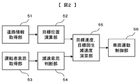
図2は、本発明の実施形態の制動支援装置に関して、主な構成要素と信号の流れを説明する図である。道路状態取得部51は、前方カメラ10f、前方レーダ11f、ナビゲーション装置6の少なくとも一つから、信号の位置,停止線の位置,信号の色,右左折可否の表示,車線の位置、車線の曲率、車線の幅、車線の数などの情報を取得する演算部である。目標停止位置演算部52は、道路状態取得部51からの情報(特に、先行車の位置、停止線の位置)に基づき、車両が停止すべき位置(以下、目標停止位置と呼ぶ)と、そこまでの距離を演算する。運転者意思取得部53は、アクセルペダル操作量センサ4、ブレーキペダル操作量センサ5や、図示しない走行モード設定スイッチからの情報によって、運転者の操作に関わる情報を取得する演算部である。減速意思判断部54は、運転者意思取得部53からの情報に基づき、運転者に減速の意思があるか否かを判断する演算部である。例えば、アクセルペダルから足が離れているときには、減速意思があると判断する。目標速度,目標加速度演算部55は、目標停止位置までの距離、運転者の減速意思,車両の運動状態に基づいて、目標停止位置での目標速度,目標停止位置で停止するまでの減速度を演算する。車両運動制御部56は、目標加速度演算部55からの目標減速度に基づいて車両運動を制御する。具体的には、モータ22に回生トルクを与えて、車両に制動力を付与する。
また、車両には運転者への情報提供を行うための情報提供手段26が備わり、走行支援の種類に応じて、画像表示、音、警告灯などによって支援の情報を提供する。情報提供手段26は例えばスピーカを内蔵したモニタ装置であり、1ヶ所だけでなく、複数箇所へ設置しても良い。
図2は、本発明の実施形態の制動支援装置に関して、主な構成要素と信号の流れを説明する図である。道路状態取得部51は、前方カメラ10f、前方レーダ11f、ナビゲーション装置6の少なくとも一つから、信号の位置,停止線の位置,信号の色,右左折可否の表示,車線の位置、車線の曲率、車線の幅、車線の数などの情報を取得する演算部である。目標停止位置演算部52は、道路状態取得部51からの情報(特に、先行車の位置、停止線の位置)に基づき、車両が停止すべき位置(以下、目標停止位置と呼ぶ)と、そこまでの距離を演算する。運転者意思取得部53は、アクセルペダル操作量センサ4、ブレーキペダル操作量センサ5や、図示しない走行モード設定スイッチからの情報によって、運転者の操作に関わる情報を取得する演算部である。減速意思判断部54は、運転者意思取得部53からの情報に基づき、運転者に減速の意思があるか否かを判断する演算部である。例えば、アクセルペダルから足が離れているときには、減速意思があると判断する。目標速度,目標加速度演算部55は、目標停止位置までの距離、運転者の減速意思,車両の運動状態に基づいて、目標停止位置での目標速度,目標停止位置で停止するまでの減速度を演算する。車両運動制御部56は、目標加速度演算部55からの目標減速度に基づいて車両運動を制御する。具体的には、モータ22に回生トルクを与えて、車両に制動力を付与する。
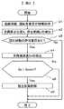
次に、本発明の実施形態の動作について、図3と図4を用いて説明する。図3は回生制動制御を実行するフローチャートであり、図4は停止線33までの回生制動制御の例である。
ステップs1にて、各種センサから、停止線33の位置などの道路情報、運転者の操作情報、速度などの車両運動情報を取得する。
ステップs2では、停止線33の位置などの道路情報に基づいて、図4に示すような、目標停止位置X,自車両31との停止線までの距離L(目標停止距離L)を求める。ステップs3では、運転者の操作量情報によって、運転者が自動減速の介入を許可している否かの判断を行う。運転者がアクセルペダルを離していれば、自動減速の許可意思があるとして、ステップs4へ進む。運転者の許可意思がないと判断すれば、制御を終了する。
ステップs4では,目標停止距離Lから、目標停止位置Xまでの目標減速度Gxを演算する。
ステップs2では、停止線33の位置などの道路情報に基づいて、図4に示すような、目標停止位置X,自車両31との停止線までの距離L(目標停止距離L)を求める。ステップs3では、運転者の操作量情報によって、運転者が自動減速の介入を許可している否かの判断を行う。運転者がアクセルペダルを離していれば、自動減速の許可意思があるとして、ステップs4へ進む。運転者の許可意思がないと判断すれば、制御を終了する。
ステップs4では,目標停止距離Lから、目標停止位置Xまでの目標減速度Gxを演算する。
ステップs5では、回生制動の要否を判断する。ステップs4で求めた目標減速度Gxが、所定の下限減速度Gxminと比較して大きければ、回生制動による減速が必要と判断し、ステップs6へ進む。一方、下限減速度Gxmin以下であれば、走行抵抗程度の減速で十分と判断し、回生制動を実施せずに制御を終了する。
ステップs6では、ステップs5で導出した目標減速度Gxを発生できるように、具体的には、モータ22を駆動して、車両に制動力を与える。
これらの処理では、停止線の位置を基準位置として、目標減速度Gxを求めたが、目標停止位置Xは停止線に限定せずに,信号の位置,交差点の位置,先行車の位置を基準位置について目標減速度Gxを求めても良い。
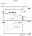
図5を用いて、本発明を実施した場合の速度、および加速度の変化を示す。図4のように、目標停止位置Xの前でアクセルペダルが離され,ブレーキペダルも操作されていないとき,目標停止距離L、速度Vに応じて、目標減速度Gxが算出され、減速度が発生する。
目標減速度Gxを算出するにあたり,目標停止位置Xまで一定の減速度で停止することを想定した停止減速度Gxsを
Gxs= V2/(2L)
から求める。すなわち停止減速度Gxsで減速を続ければ,目標停止位置Xで停止できることになる。次に,ブレーキペダルが踏まれていないときの,回生制動のみによる目標減速度Gxが,
Gx<Gxs
となるように目標減速度Gxを設定する。このように,目標減速度Gxを停止減速度よりも小さく設定することで,回生制動のみの減速度では目標停止位置Xで停止できないことになるため,運転者のブレーキペダル操作を促すことができる。
Gxs= V2/(2L)
から求める。すなわち停止減速度Gxsで減速を続ければ,目標停止位置Xで停止できることになる。次に,ブレーキペダルが踏まれていないときの,回生制動のみによる目標減速度Gxが,
Gx<Gxs
となるように目標減速度Gxを設定する。このように,目標減速度Gxを停止減速度よりも小さく設定することで,回生制動のみの減速度では目標停止位置Xで停止できないことになるため,運転者のブレーキペダル操作を促すことができる。
Gxを設定するために,回生制動のみの減速度する場合に目標停止位置を通過するときの目標速度Vsを次式で設定する。
Gx=(V2―Vs2)/(2L)
Gx=(V2―Vs2)/(2L)
目標速度Vsをゼロより大きく設定することで,目標減速度Gxは停止減速度Gxsよりも必然的に小さくなり,運転者に対してブレーキペダルの操作を促すことができる。
速度Vの変化は,停止減速度Gxsでの減速を想定すれば,図5(b)の速度変化のようになり,目標停止位置Xで停車することになる。一方,回生制動のみの減速度では,図5(a)の速度変化のようになり,目標停止位置Xでの速度Vsはゼロより大きくなる。
運転者が目標停止位置Xで停止する意思があれば,運転者は回生制動の減速度Gxに加えて,ブレーキペダル操作による摩擦制動にて減速度の不足分ΔGxを発生する。これにより,回生制動と摩擦制動の併用によって目標停止位置で停車することができる。
目標減速度Gxを,停止減速度Gxs(=V2/(2L))よりも小さく設定する場合に,アクセルペダルを話した時点の速度Vと停止距離Lを継続して使用することも可能であるが,アクセルペダル解放のタイミングに限定されるわけではない。つまり,時々刻々変化するVとLに応じて停止減速度Gxsを遂次算出し,その時点の目標減速度Gxを停止減速度Gxsよりも小さく設定することで,回生制動のみでは目標停止位置で停車できないことを運転者に認知させることができる。
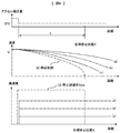
次に図6を用いて、外界情報に応じて減速度の大きさをより緻密に調整する場合の制御例を示す。図4の説明では,停止線での停車を想定したが,信号が伴う停止線の場合は,停止線で停止すべきか否かは,信号の色によって異なる。また,ある時点での信号が赤色であっても,自車両が信号が通過するタイミングで青色に変わることが予測できれば,停止線で停止する必要はなくなる。したがって,停止線で停止すべき確率(確度)に応じて減速度を変化させることによって,より運転者の運転操作に近づけることができ,回生制動制御の違和感を低減できる。
目標減速度Gxを,停止減速度Gxs(=V2/(2L))よりも小さく設定する場合に,アクセルペダルを話した時点の速度Vと停止距離Lを継続して使用することも可能であるが,アクセルペダル解放のタイミングに限定されるわけではない。つまり,時々刻々変化するVとLに応じて停止減速度Gxsを遂次算出し,その時点の目標減速度Gxを停止減速度Gxsよりも小さく設定することで,回生制動のみでは目標停止位置で停車できないことを運転者に認知させることができる。
次に図6を用いて、外界情報に応じて減速度の大きさをより緻密に調整する場合の制御例を示す。図4の説明では,停止線での停車を想定したが,信号が伴う停止線の場合は,停止線で停止すべきか否かは,信号の色によって異なる。また,ある時点での信号が赤色であっても,自車両が信号が通過するタイミングで青色に変わることが予測できれば,停止線で停止する必要はなくなる。したがって,停止線で停止すべき確率(確度)に応じて減速度を変化させることによって,より運転者の運転操作に近づけることができ,回生制動制御の違和感を低減できる。
信号の色や,色の変化は,必ずしも全ての外界センサで検出できるとは限らない。前方カメラ10fがモノクロカメラであれば,信号の位置,信号までの距離は検出できても,色の検出は難しい。また,前方カメラ10fがカラーカメラであれば,色の検出の可能となる。さらに,通信機能を備えたナビゲーション装置6が,信号機の色の変化タイミングに関する情報を取得できれば,自車両の速度と信号変化のタイミング情報から,自車両が現在の速度のまま交差点を通過できるか否かを判断できる。
図6では,(a)信号機の位置は検出できるが,色の情報が不明の場合,(b)信号機の位置も色も検出できるが,色の変化タイミングは検出できない場合,(c)信号機の位置,色の情報に加え,変化タイミングも検出できる場合,の3パターンに応じて,目標減速度Gxを変化させている。
信号機の位置は検出できるが,色の情報が不明の場合の速度と減速度の変化を図6-(a)で示す。色情報が不明の場合,停止すべき場合と停止する必要がない場合の確率は,おおよそ半々程度と考えられる。このとき比較的弱めの目標減速度Gxとすることで,運転者操作への依存度を高める。
信号機の位置と色を検出できるが,色変化タイミングは検出できない場合の速度と減速度の変化を図6-(b)で示す。信号機の色が赤色と判別できていれば,停止すべき確率は,停止不要の確率よりも高いと考えられるので,比較的強めの目標減速度Gxを設定し,比較的大きい回生量を確保する。
信号機の位置,色の情報に加え,変化タイミングも検出できる場合の速度と減速度の変化を図6-(c)で示す。信号機で停車することをほぼ確実に予測できるので,停車が必要と判断されれば,上記(a)や(b)の場合よりも大きい目標減速度Gxを設定し,強い回生制動を作用させる。
これら信号機の色で目標減速度Gxを変化させる場合においても,その大きさは,停止減速度Gxsよりも小さく設定することで,運転者の操作を促す。また,信号機の情報に応じて停止すべき確率を推定し,目標減速度Gxを調節することで,運転者の違和感を低減できる。
次に図7を用いて、外界情報に応じて減速度の大きさを調整する別の制御例を示す。図7の左図のように,自車両31の前方に停止車両(先行車32)がある場合,その車両が自車線内の中央に停車していれば,自車両31もそれに衝突しないよう減速し,停車する必要がある。しかし,図7の右図のように,前方の停止車両が自車線から逸れた位置に停車していれば,自車両31は減速する必要がない。このように,自車両31が前方の車両に対して停車すべきか否かは,前方車両との距離だけではなく,自車線からのオフセット量Yによっても変化する。
図7の左図のように,高い確率で停車が必要と判断できる場合には,図6-(c)のように,比較的強い回生制動を作用させ,回生量の増加を図る。一方,図7の右図のように,停止する必要性が低い場合は,図6-(a)のように,比較的弱い回生制動に留め,運転者の違和感を低減する。
次に図8を用いて、外界情報に応じて減速度の大きさを調整する別の制御例を示す。図8では,前方カメラ10fまたは前方レーダ11fが,自車の前方に速度Vaで走行中の先行車32を検知できており,自車の速度Vの方が速いため(V>Va),先行車32へ接近している状態である。
目標車間距離Dで追従走行することを想定し,自車の目標速度は先行車と同じVaにすることを目標とする。減速しながら接近する間の減速度を車間確保減速度Gxcとし,一定値とすると,
Gxc=(V2―Va2)/(2L)
から算出する。すなわち車間確保減速度Gxcで減速を続ければ,所定時間内の経過時間後に目標車間距離Dで追従走行できることになる。次に,ブレーキペダルが踏まれていないときの,回生制動のみによる目標減速度Gxが,
Gx<Gxc
となるように目標減速度Gxを設定する。このように,目標減速度Gxを車間確保減速度Gxcよりも小さく設定することで,回生制動のみの減速度では目標車間距離Dを越えて先行車へ接近してしまうことになるため,運転者のブレーキペダル操作を促すことができる。
以上のような回生減速度Gxの大小を,情報提示手段26で運転者に提示することで,運転者の違和感をより低減できる。また,目標停止位置での目標速度Vsを表示することで,コントローラ1の意図を運転者に提示することもできる。また,コントローラ1がドライバのブレーキペダル操作を想定しているにもかかわらず,運転者のブレーキペダル操作が行われない場合,音や警告灯によって運転者に警告する。これによって,運転者のブレーキペダル操作をより確実に促すことができる。
また,違和感低減には,運転者の個性に合わせた制御を行うことも有効である。例えば車両システムを起動するためのキーに個人認証の機能があれば,個人認証の結果に基づき,個々の運転者の運転パターンを学習して,回生減速度を調整することもできる。これによって,回生減速度の強弱に起因する違和感を低減することができる。
以上のように、本発明を適用した実施形態によれば、停止位置や先行車などの外界環境に応じて回生制動による減速度を調整し,目標停止位置で停止する減速度や,目標車間距離を確保する減速度よりも小さく設定する。これにより、運転者にブレーキペダルの操作を促すことができ,運転者に停車動作や減速度の微調整を委ねることができ,運転者の違和感を低減可能な回生制動制御装置を提供できる。
以上のように、本発明を適用した実施形態によれば、停止位置や先行車などの外界環境に応じて回生制動による減速度を調整し,目標停止位置で停止する減速度や,目標車間距離を確保する減速度よりも小さく設定する。これにより、運転者にブレーキペダルの操作を促すことができ,運転者に停車動作や減速度の微調整を委ねることができ,運転者の違和感を低減可能な回生制動制御装置を提供できる。
1…コントローラ
2…操舵角センサ
3…方向指示器レバー
4…アクセルペダル操作量センサ
5…ブレーキペダル操作量センサ
6…ナビゲーション装置
7fL,7fR,7rL,7rR…車輪速度センサ
8…車両挙動センサ
10f…前方カメラ
10r…後方カメラ
11f…前方レーダ
11r…後方レーダ
21…エンジン
22…モータ
23…摩擦制動装置
2…アクセルペダル
25…ブレーキペダル
26…情報提示手段
31…自車両
32…先行車
33…停止線
51…道路状態取得部
52…目標停止位置演算部
53…運転者意思取得部
54…減速意思判断部
55…目標加速度演算部
56…車両運動制御部
2…操舵角センサ
3…方向指示器レバー
4…アクセルペダル操作量センサ
5…ブレーキペダル操作量センサ
6…ナビゲーション装置
7fL,7fR,7rL,7rR…車輪速度センサ
8…車両挙動センサ
10f…前方カメラ
10r…後方カメラ
11f…前方レーダ
11r…後方レーダ
21…エンジン
22…モータ
23…摩擦制動装置
2…アクセルペダル
25…ブレーキペダル
26…情報提示手段
31…自車両
32…先行車
33…停止線
51…道路状態取得部
52…目標停止位置演算部
53…運転者意思取得部
54…減速意思判断部
55…目標加速度演算部
56…車両運動制御部
Claims (5)
- 運転者のブレーキペダル操作に応じて移動体の運動エネルギを熱エネルギとして放出する摩擦制動装置と,車両の運動エネルギを電気エネルギとして回生するモータと,車両が停止すべき位置または先行車との車間距離を検出する外界認識センサと,車両の目標停止位置または目標車間距離を演算する目標位置演算手段を備え,運転者がアクセルペダルおよびブレーキペダルの操作を行わないときのモータによる回生減速度を,前記目標停止位置で停止するために必要な減速度,または前記目標車間距離で先行車との相対速度をゼロにするために必要な減速度よりも小さく制御することを特徴とする車両(移動体)の駆動制御装置。
- 運転者のブレーキペダル操作に応じて移動体の運動エネルギを熱エネルギとして放出する摩擦制動装置と,車両の運動エネルギを電気エネルギとして回生するモータと,車両が停止すべき位置または先行車との車間距離を検出する外界認識センサと,車両の目標停止位置または目標車間距離を演算する目標位置演算手段を備え,運転者がアクセルペダルとブレーキペダルの操作を行わない状態で,モータによって回生減速度を発生させる場合,前記目標停止位置における車両の速度,または目標車間距離における先行車との相対速度をゼロより大きい速度に制御することを特徴とする車両(移動体)の駆動制御装置。
- 請求項1と請求項2のいずれかに記載の駆動制御装置において、運転者が目標停止位置で停止すべき確率が高いほど,モータによる回生減速度を大きく,または停止位置での速度が小さくなるように,回生制動力を制御する車両(移動体)の駆動制御装置。
- 請求項3に記載の駆動制御装置において、信号機の色が識別できる場合は,信号機の色が識別できない場合よりも,モータによる回生減速度を大きく,または停止位置での速度が小さくなるように,回生制動力を制御する車両(移動体)の駆動制御装置。
- 請求項3に記載の駆動制御装置において、車両に対する前記先行車の左右方向の位置のオフセット量が小さいほど,目標停止位置での速度が高くなるように制御 モータによる回生減速度を大きく,または停止位置での速度が小さくなるように,回生制動力を制御する車両(移動体)の駆動制御装置。
Priority Applications (3)
| Application Number | Priority Date | Filing Date | Title |
|---|---|---|---|
| EP14862782.1A EP3069947A4 (en) | 2013-11-12 | 2014-10-20 | Moving body drive control device |
| US15/035,775 US20160264003A1 (en) | 2013-11-12 | 2014-10-20 | Moving Body Drive Control Device |
| CN201480061893.9A CN105722738B (zh) | 2013-11-12 | 2014-10-20 | 移动体的驱动控制装置 |
Applications Claiming Priority (2)
| Application Number | Priority Date | Filing Date | Title |
|---|---|---|---|
| JP2013233617A JP6177666B2 (ja) | 2013-11-12 | 2013-11-12 | 移動体の駆動制御装置 |
| JP2013-233617 | 2013-11-12 |
Publications (1)
| Publication Number | Publication Date |
|---|---|
| WO2015072286A1 true WO2015072286A1 (ja) | 2015-05-21 |
Family
ID=53057228
Family Applications (1)
| Application Number | Title | Priority Date | Filing Date |
|---|---|---|---|
| PCT/JP2014/077771 WO2015072286A1 (ja) | 2013-11-12 | 2014-10-20 | 移動体の駆動制御装置 |
Country Status (5)
| Country | Link |
|---|---|
| US (1) | US20160264003A1 (ja) |
| EP (1) | EP3069947A4 (ja) |
| JP (1) | JP6177666B2 (ja) |
| CN (1) | CN105722738B (ja) |
| WO (1) | WO2015072286A1 (ja) |
Cited By (2)
| Publication number | Priority date | Publication date | Assignee | Title |
|---|---|---|---|---|
| CN106347137A (zh) * | 2015-07-15 | 2017-01-25 | 福特全球技术公司 | 自适应再生制动方法和系统 |
| JP2018173723A (ja) * | 2017-03-31 | 2018-11-08 | 株式会社Subaru | 車両の走行制御システム |
Families Citing this family (31)
| Publication number | Priority date | Publication date | Assignee | Title |
|---|---|---|---|---|
| WO2014192367A1 (ja) * | 2013-05-31 | 2014-12-04 | 日立オートモティブシステムズ株式会社 | 車両制御装置及び車両制御方法 |
| JP6233063B2 (ja) * | 2014-01-31 | 2017-11-22 | トヨタ自動車株式会社 | 車両 |
| JP6421565B2 (ja) * | 2014-11-26 | 2018-11-14 | 株式会社デンソー | 運転支援装置 |
| JP6459823B2 (ja) * | 2015-07-24 | 2019-01-30 | トヨタ自動車株式会社 | 車両制御装置 |
| JP6557560B2 (ja) * | 2015-09-07 | 2019-08-07 | 本田技研工業株式会社 | 走行制御装置 |
| CN105118015A (zh) * | 2015-09-21 | 2015-12-02 | 无锡知谷网络科技有限公司 | 用于公共场所的信息提示方法及移动服务终端 |
| KR101712285B1 (ko) * | 2015-09-23 | 2017-03-03 | 쌍용자동차 주식회사 | 하이브리드 자동차 또는 전기자동차의 회생제동 제어방법 |
| CN105730252A (zh) * | 2016-02-02 | 2016-07-06 | 江苏金坛汽车工业有限公司 | 纯电动汽车再生制动系统 |
| US10160437B2 (en) | 2016-02-29 | 2018-12-25 | Magna Electronics Inc. | Vehicle control system with reverse assist |
| EP3611591B1 (en) * | 2017-04-13 | 2021-12-22 | Panasonic Corporation | Method for controlling an electrically driven vehicle and electrically driven vehicle controlled with the method |
| DE102017004536A1 (de) * | 2017-05-11 | 2018-11-15 | Lucas Automotive Gmbh | System und Verfahren zur vorausschauenden Geschwindigkeitsbeeinflussung eines Kraftfahrzeugs |
| KR101944310B1 (ko) * | 2017-10-31 | 2019-02-01 | 쌍용자동차 주식회사 | 사륜구동 하이브리드 자동차의 코스팅 및 회생제동 제어방법 |
| US10895460B2 (en) * | 2017-11-06 | 2021-01-19 | Cybernet Systems Corporation | System and method for generating precise road lane map data |
| KR102429505B1 (ko) * | 2017-12-28 | 2022-08-05 | 현대자동차주식회사 | 차량의 회생 제동 제어 장치 및 방법 |
| JP6640887B2 (ja) * | 2018-01-04 | 2020-02-05 | 本田技研工業株式会社 | 制御装置及び制御方法 |
| DE102018203560A1 (de) * | 2018-03-08 | 2019-09-12 | Bayerische Motoren Werke Aktiengesellschaft | Verfahren und Steuereinheit zur Erkennung einer Fahrspurbegrenzung |
| CN108545069B (zh) | 2018-03-30 | 2020-03-10 | 北京图森未来科技有限公司 | 一种车辆停车控制方法及装置 |
| CN110641429B (zh) * | 2018-06-25 | 2021-09-21 | 比亚迪股份有限公司 | 一种车辆控制方法、系统及车辆 |
| EP3829943B1 (en) | 2018-08-01 | 2023-09-27 | Cummins, Inc. | System and method for regenerative braking torque scheduling |
| US11345327B2 (en) | 2018-08-06 | 2022-05-31 | Xl Hybrids, Inc. | Throttle signal controller for a dynamic hybrid vehicle |
| DE102018214953A1 (de) * | 2018-09-04 | 2020-03-05 | Robert Bosch Gmbh | Verfahren zum Betreiben eines Kraftfahrzeugs, Steuergerät, Kraftfahrzeug |
| KR102574116B1 (ko) * | 2018-11-09 | 2023-09-05 | 현대자동차주식회사 | 차량 및 그 제어 방법 |
| CN111169290B (zh) * | 2018-11-09 | 2021-11-23 | 广州汽车集团股份有限公司 | 一种车辆行驶速度控制方法和系统 |
| CN109501601B (zh) * | 2018-12-11 | 2020-06-23 | 湖南中联重科智能技术有限公司 | 高空剪叉车制动控制方法、装置及高空剪叉车 |
| KR102175793B1 (ko) * | 2018-12-28 | 2020-11-06 | 주식회사대성엘텍 | 인지 장애 경고 방법 및 장치 |
| CN112622626A (zh) * | 2019-09-24 | 2021-04-09 | 比亚迪股份有限公司 | 电动汽车的控制方法及装置,电动汽车 |
| CN110686587B (zh) * | 2019-09-27 | 2022-02-15 | 王磊 | 制动距离的检测方法及装置 |
| WO2021084574A1 (ja) * | 2019-10-28 | 2021-05-06 | 日産自動車株式会社 | 電動車両の制御方法及び電動車両の制御装置 |
| JP7452482B2 (ja) * | 2021-03-26 | 2024-03-19 | トヨタ自動車株式会社 | 車両制御装置、車両、車両制御方法及び制御プログラム |
| CN114274956A (zh) * | 2021-12-28 | 2022-04-05 | 上海集度汽车有限公司 | 车辆巡航控制方法、装置、车辆及可读存储介质 |
| CN117734655B (zh) * | 2024-02-19 | 2024-06-21 | 中汽研汽车检验中心(广州)有限公司 | 实时制动踏板力提示方法、装置、电子设备、存储介质 |
Citations (4)
| Publication number | Priority date | Publication date | Assignee | Title |
|---|---|---|---|---|
| JPH0937407A (ja) | 1995-07-18 | 1997-02-07 | Toyota Motor Corp | 回生制動制御装置 |
| JP2005039908A (ja) * | 2003-07-17 | 2005-02-10 | Mitsubishi Motors Corp | ハイブリッド車両の回生制動制御装置 |
| JP2009067350A (ja) * | 2007-09-18 | 2009-04-02 | Aisin Aw Co Ltd | 車両消費エネルギ推定装置、車両消費エネルギ推定方法及びコンピュータプログラム |
| JP2013109705A (ja) * | 2011-11-24 | 2013-06-06 | Toyota Motor Corp | 運転支援装置及び運転支援方法 |
Family Cites Families (8)
| Publication number | Priority date | Publication date | Assignee | Title |
|---|---|---|---|---|
| US7360615B2 (en) * | 2004-06-09 | 2008-04-22 | General Motors Corporation | Predictive energy management system for hybrid electric vehicles |
| JP4506741B2 (ja) * | 2006-10-11 | 2010-07-21 | マツダ株式会社 | 車両用発電機の制御装置 |
| US8073605B2 (en) * | 2008-08-13 | 2011-12-06 | GM Global Technology Operations LLC | Method of managing power flow in a vehicle |
| DE102008061821B4 (de) * | 2008-12-11 | 2024-09-12 | Bayerische Motoren Werke Aktiengesellschaft | Verfahren zur Rekuperation von Energie in einem Kraftfahrzeug |
| JP2011024353A (ja) * | 2009-07-16 | 2011-02-03 | Aisin Aw Co Ltd | 案内装置、案内方法、及び案内プログラム |
| JP2012034501A (ja) * | 2010-07-30 | 2012-02-16 | Aisin Aw Co Ltd | 運転支援装置、運転支援方法、及び運転支援プログラム |
| US8855844B2 (en) * | 2011-10-11 | 2014-10-07 | Robert Bosch Gmbh | System and method for optimal deceleration of a vehicle using regenerative braking |
| JP5880500B2 (ja) * | 2013-08-29 | 2016-03-09 | トヨタ自動車株式会社 | 車両 |
-
2013
- 2013-11-12 JP JP2013233617A patent/JP6177666B2/ja not_active Expired - Fee Related
-
2014
- 2014-10-20 EP EP14862782.1A patent/EP3069947A4/en not_active Withdrawn
- 2014-10-20 US US15/035,775 patent/US20160264003A1/en not_active Abandoned
- 2014-10-20 WO PCT/JP2014/077771 patent/WO2015072286A1/ja active Application Filing
- 2014-10-20 CN CN201480061893.9A patent/CN105722738B/zh not_active Expired - Fee Related
Patent Citations (4)
| Publication number | Priority date | Publication date | Assignee | Title |
|---|---|---|---|---|
| JPH0937407A (ja) | 1995-07-18 | 1997-02-07 | Toyota Motor Corp | 回生制動制御装置 |
| JP2005039908A (ja) * | 2003-07-17 | 2005-02-10 | Mitsubishi Motors Corp | ハイブリッド車両の回生制動制御装置 |
| JP2009067350A (ja) * | 2007-09-18 | 2009-04-02 | Aisin Aw Co Ltd | 車両消費エネルギ推定装置、車両消費エネルギ推定方法及びコンピュータプログラム |
| JP2013109705A (ja) * | 2011-11-24 | 2013-06-06 | Toyota Motor Corp | 運転支援装置及び運転支援方法 |
Non-Patent Citations (1)
| Title |
|---|
| See also references of EP3069947A4 |
Cited By (4)
| Publication number | Priority date | Publication date | Assignee | Title |
|---|---|---|---|---|
| CN106347137A (zh) * | 2015-07-15 | 2017-01-25 | 福特全球技术公司 | 自适应再生制动方法和系统 |
| CN106347137B (zh) * | 2015-07-15 | 2022-02-01 | 福特全球技术公司 | 自适应再生制动方法和系统 |
| JP2018173723A (ja) * | 2017-03-31 | 2018-11-08 | 株式会社Subaru | 車両の走行制御システム |
| US10640116B2 (en) | 2017-03-31 | 2020-05-05 | Subaru Corporation | Traveling control system and method for vehicle |
Also Published As
| Publication number | Publication date |
|---|---|
| CN105722738B (zh) | 2018-10-16 |
| EP3069947A4 (en) | 2017-06-14 |
| JP2015093560A (ja) | 2015-05-18 |
| US20160264003A1 (en) | 2016-09-15 |
| CN105722738A (zh) | 2016-06-29 |
| EP3069947A1 (en) | 2016-09-21 |
| JP6177666B2 (ja) | 2017-08-09 |
Similar Documents
| Publication | Publication Date | Title |
|---|---|---|
| JP6177666B2 (ja) | 移動体の駆動制御装置 | |
| JP6981837B2 (ja) | 車両の運転支援制御装置 | |
| KR101864938B1 (ko) | 충돌 회피 지원 장치 | |
| KR102016186B1 (ko) | 드라이빙 안정성을 향상시키는 방법 | |
| JP6332180B2 (ja) | 車両の制御装置 | |
| JP5139939B2 (ja) | 車両の減速支援装置 | |
| JP6332179B2 (ja) | 車両の制御装置 | |
| JP5598531B2 (ja) | 車両制御装置 | |
| JP5300357B2 (ja) | 衝突防止支援装置 | |
| JP6286192B2 (ja) | 移動体の駆動制御装置 | |
| WO2013072994A1 (ja) | 運転支援装置 | |
| WO2013046301A1 (ja) | 車両の運転支援システム | |
| WO2010032556A1 (ja) | 車両制御装置 | |
| WO2013073014A1 (ja) | 運転支援装置 | |
| JP2017001597A (ja) | 自動運転装置 | |
| EP2623387A1 (en) | Drive-assisting apparatus and drive-assisting method | |
| WO2019155880A1 (ja) | 車両制御装置 | |
| CN110861644A (zh) | 驱动力控制装置 | |
| CN110588640B (zh) | 碰撞减轻装置 | |
| CN110799403A (zh) | 车辆控制装置 | |
| JP2020044938A (ja) | 車両の制御システム及び車両の制御方法 | |
| WO2018186012A1 (ja) | 車両制御装置 | |
| JP2019206257A (ja) | 車両制御システム | |
| JP2019206258A (ja) | 車両制御システム | |
| JP7222343B2 (ja) | 運転支援装置 |
Legal Events
| Date | Code | Title | Description |
|---|---|---|---|
| 121 | Ep: the epo has been informed by wipo that ep was designated in this application |
Ref document number: 14862782 Country of ref document: EP Kind code of ref document: A1 |
|
| REEP | Request for entry into the european phase |
Ref document number: 2014862782 Country of ref document: EP |
|
| WWE | Wipo information: entry into national phase |
Ref document number: 15035775 Country of ref document: US Ref document number: 2014862782 Country of ref document: EP |
|
| NENP | Non-entry into the national phase |
Ref country code: DE |