WO2015072281A1 - 時刻修正システム、電子機器、時計及びプログラム - Google Patents
時刻修正システム、電子機器、時計及びプログラム Download PDFInfo
- Publication number
- WO2015072281A1 WO2015072281A1 PCT/JP2014/077682 JP2014077682W WO2015072281A1 WO 2015072281 A1 WO2015072281 A1 WO 2015072281A1 JP 2014077682 W JP2014077682 W JP 2014077682W WO 2015072281 A1 WO2015072281 A1 WO 2015072281A1
- Authority
- WO
- WIPO (PCT)
- Prior art keywords
- time
- unit
- correction amount
- time correction
- electronic device
- Prior art date
- Legal status (The legal status is an assumption and is not a legal conclusion. Google has not performed a legal analysis and makes no representation as to the accuracy of the status listed.)
- Ceased
Links
Images





Classifications
-
- G—PHYSICS
- G04—HOROLOGY
- G04R—RADIO-CONTROLLED TIME-PIECES
- G04R20/00—Setting the time according to the time information carried or implied by the radio signal
- G04R20/26—Setting the time according to the time information carried or implied by the radio signal the radio signal being a near-field communication signal
-
- G—PHYSICS
- G04—HOROLOGY
- G04C—ELECTROMECHANICAL CLOCKS OR WATCHES
- G04C10/00—Arrangements of electric power supplies in time-pieces
- G04C10/02—Arrangements of electric power supplies in time-pieces the power supply being a radioactive or photovoltaic source
-
- G—PHYSICS
- G04—HOROLOGY
- G04C—ELECTROMECHANICAL CLOCKS OR WATCHES
- G04C9/00—Electrically-actuated devices for setting the time-indicating means
-
- G—PHYSICS
- G04—HOROLOGY
- G04G—ELECTRONIC TIME-PIECES
- G04G19/00—Electric power supply circuits specially adapted for use in electronic time-pieces
-
- G—PHYSICS
- G04—HOROLOGY
- G04G—ELECTRONIC TIME-PIECES
- G04G5/00—Setting, i.e. correcting or changing, the time-indication
Definitions
- the present invention relates to a time correction system, an electronic device, a clock, and a program.
- This application claims priority based on Japanese Patent Application Nos. 2013-234254 and 2013-234255 filed in Japan on November 12, 2013, the contents of which are incorporated herein by reference.
- a dial of a watch is imaged, pointer position information indicating the position of a pointer indicating an information notation formed on the dial is generated based on a captured image of the dial, and the generated pointer position information is written in the watch.
- An apparatus is known (see, for example, Patent Document 1).
- a time adjustment system that corrects the time of a clock using a correction instruction device such as a computer is known (for example, see Patent Document 2).
- the correction instruction device receives input of instruction time data instructed by a timepiece, and transmits reference time data and instruction time data to the timepiece.
- the timepiece corrects the pointer instruction based on the reference time data and the instruction time data received from the correction instruction device.
- JP 2010-12912 A Japanese Patent No. 4200835
- the timepiece calculates the difference based on the reference time data and the instruction time data received by the timepiece.
- Some aspects of the present invention provide a time correction system, an electronic device, a clock, and a program capable of performing time correction stably without adopting a complicated configuration.
- One aspect of the present invention is a time adjustment system including a timepiece having a display unit that indicates time by hands and an electronic device, the electronic device including an acquisition unit that acquires a current time, and the display of the timepiece An input unit that receives an input of the time indicated by the unit, and a time for calculating a time correction amount for correcting the time of the clock from the difference between the time when the input unit receives the input and the current time acquired by the acquisition unit A correction amount calculation unit; and a transmission unit that transmits the time correction amount calculated by the time correction amount calculation unit to the timepiece on light, and the timepiece receives the time correction amount from the electronic device.
- a control unit controls the reception period in the receiving unit and the storage period in the power storage unit, a time correction system characterized by receiving the time correction amount in the reception period.
- FIG. 6 is a timing chart for explaining an operation example of the electronic timepiece according to the first embodiment of the present invention. It is the flowchart which showed the process sequence of the time correction process which the electronic device by the 1st Embodiment of this invention performs. It is the flowchart which showed the process sequence of the time correction process which the electronic timepiece by the 1st Embodiment of this invention performs. It is the flowchart which showed the process sequence of the time correction process which the electronic device by the 2nd Embodiment of this invention performs. It is the flowchart which showed the process sequence of the time correction process which the electronic timepiece by the 2nd Embodiment of this invention performs.
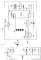
- FIG. 1 is a schematic diagram illustrating a configuration of a time correction system 1 according to the present embodiment.
- the time correction system 1 includes an electronic device 10 and an electronic timepiece 20.
- the electronic device 10 is, for example, an electronic device such as a smartphone, a mobile phone, or a tablet terminal.
- the electronic device 10 includes a time data acquisition unit 101, a control unit 102, a light source 103, an imaging unit 104, a display unit 105, and an input unit 106.
- the time data acquisition unit 101 acquires the current time (hour minute second). For example, the time data acquisition unit 101 obtains the current time by accessing a time server on the Internet, the method of acquiring the current time using GPS (Global Positioning System), and the control signal from the base station. A method for obtaining the current time is used. Note that any method may be used to acquire the current time.
- GPS Global Positioning System
- the control unit 102 controls each unit included in the electronic device 10.
- the control unit 102 (identification unit) identifies the time indicated by the pointer 2082 from the image of the display unit 208 of the electronic timepiece 20 captured by the imaging unit 104. Specifically, first, the control unit 102 extracts the hour hand, the minute hand, and the second hand from the image of the display unit 208. Then, the control unit 102 determines the time indicated by the pointer 2082 based on the positional relationship among the marks (for example, numbers 1 to 12) printed on the dial 2081, the extracted hour hand, the minute hand, and the second hand. Specify hour, minute, second).
- control unit 102 (time correction amount calculation unit) corrects the time of the electronic timepiece 20 from the difference between the time specified based on the image of the display unit 208 and the current time acquired by the time data acquisition unit 101. The time correction amount is calculated. Then, the control unit 102 outputs time correction amount data indicating the calculated time correction amount as an optical signal using the light source 103.
- the light source 103 is, for example, a flash LED (Light Emitting Diode) included in the electronic device 10 or a backlight of a liquid crystal display.
- the light source 103 operates as a transmission unit that transmits an optical signal indicating time correction amount data to the electronic timepiece 20.
- the imaging unit 104 captures an image of the subject (the display unit 208 of the electronic timepiece 20) and generates an image.
- the display unit 105 is a liquid crystal display (LCD, Liquid Crystal Display) or the like, and displays information.
- the input unit 106 includes a switch and receives an input.
- the electronic clock 20 is a clock that displays the time in an analog display.
- the electronic timepiece 20 includes a solar battery 201, a control circuit 202, a switch 203, a secondary battery 204, a diode 205, a reference signal generation circuit 206, a stepping motor 207, and a display unit 208.
- the display unit 208 includes a dial plate 2081, a pointer 2082, and a date unit 2083.
- the solar cell 201 operates as a power generation unit that receives light (sun, illumination, etc.) and converts it into electric energy during the charging period. Further, the solar cell 201 operates as a receiving unit that performs optical communication with the electronic device 10 during the communication period and receives an optical signal indicating time correction amount data from the electronic device 10. The charging period and the communication period will be described later.
- the control circuit 202 controls each part included in the electronic timepiece 20.
- the control circuit 202 controls charging of the secondary battery 204 by the solar battery 201.
- the control circuit 202 performs overcharge prevention control of the secondary battery 204.
- the control circuit 202 performs optical communication using the solar cell 201.
- the control circuit 202 operates with electric power output from the secondary battery 204 connected to the power supply terminal and the GND terminal.
- the control circuit 202 determines the charge state (full charge, overdischarge, etc.) of the secondary battery 204 by detecting the output voltage of the secondary battery 204, and performs predetermined charge control.
- control circuit 202 performs on / off control of the switch 203 by a control signal output from the control terminal in accordance with the state of charge of the secondary battery 204. Accordingly, the control circuit 202 charges the secondary battery 204 by connecting the solar battery 201 and the secondary battery 204. In addition, the control circuit 202 prevents the secondary battery 204 from being overcharged by disconnecting the solar battery 201 and the secondary battery 204.
- control circuit 202 outputs a switch control signal based on the reference signal output from the reference signal generation circuit 206, and performs on / off control of the switch 203.
- control circuit 202 connects the solar battery 201 and the secondary battery 204 and disconnects the solar battery 201 and the secondary battery 204.
- control circuit 202 detects the output voltage of the solar cell 201 input to the input terminal during the communication period, and converts the detected voltage into an electric signal, so that an external device (in this embodiment) can be used.
- the time correction amount data transmitted from the electronic device 10) by optical communication is received.
- the control circuit 202 drives the stepping motor 207 based on the received time correction amount data, and corrects the time indicated by the pointer 2082.
- the switch 203 connects the solar battery 201 and the secondary battery 204 and disconnects the solar battery 201 and the secondary battery 204 based on a switch control signal input from the control circuit 202.
- the secondary battery 204 supplies power to each unit included in the electronic timepiece 20.
- the diode 205 prevents current from flowing backward to the secondary battery 204.
- the reference signal generation circuit 206 includes an oscillation circuit (for example, 32 kHz) and a frequency dividing circuit, and generates a reference signal of 1 Hz, for example.
- the stepping motor 207 drives (rotates) the pointer 2082 and the date portion 2083 based on the pulse signal input from the control circuit 202.
- the display unit 208 displays time and date in an analog display using a dial plate 2081, a pointer 2082, and a date unit 2083.
- the display unit 208 indicates the time by a dial plate 2081 and a pointer 2082, and indicates the date by a date unit 2083.
- the storage unit 209 is a nonvolatile memory, for example, and stores data used by each unit included in the electronic timepiece 20.
- the input unit 210 receives an operation input input by a user.
- the electronic device 10 transmits data using the light source 103.
- the electronic device 10 causes the light source 103 to emit light when transmitting “1”, and turns off the light source 103 when transmitting “0”.
- the electronic timepiece 20 receives data using the solar cell 201.
- the control circuit 202 of the electronic timepiece 20 determines that “1” is received when the solar cell 201 receives light and generates a voltage, and “0” when the solar cell 201 does not generate a voltage. "Is received.
- the switch 203 is controlled to disconnect the solar battery 201 and the secondary battery 204 in order to detect the voltage generated by the solar battery 201 with higher accuracy.
- a period during which the solar battery 201 and the secondary battery 204 are disconnected is referred to as a “communication period (OFF period)”.
- the switch 203 is controlled to connect the solar battery 201 and the secondary battery 204.
- a period in which the solar battery 201 and the secondary battery 204 are connected is referred to as a “charging period (ON period)”. Thereby, data can be received with higher accuracy during the reception period.
- the electronic timepiece 20 is normally set as a charging period, and a short communication period is provided for each fixed period. If the electronic timepiece 20 receives a synchronization signal from the electronic device 10 during a short communication period, the electronic timepiece 20 continues the communication period until time correction amount data is received. On the other hand, when the electronic timepiece 20 does not receive the synchronization signal from the electronic device 10 during the communication period, the electronic timepiece 20 is set to the charging period.
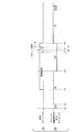
- FIG. 2A is a timing chart showing the transmission timing of the synchronization signal, the start signal, and the time correction amount data that the electronic device 10 transmits to the electronic timepiece 20.
- FIG. 2B is a timing chart showing the output timing of the switch control signal output from the control circuit 202 of the electronic timepiece 20.
- the electronic device 10 transmits a synchronization signal (time t3 to time t5) when transmitting time correction amount data. Thereafter, the electronic device 10 transmits a start signal (time t6 to time t7). Thereafter, the electronic device 10 transmits time correction amount data (time t8 to time t9).
- the electronic timepiece 20 turns off the switch 203 after the elapse of a certain time from the transition to the charging period, and shifts to the communication period (time t1).
- the electronic timepiece 20 does not receive the synchronization signal after shifting to the communication period, and after a certain time has elapsed, turns on the switch 203 and shifts to the charging period (time t2).
- the electronic timepiece 20 turns off the switch 203 after the elapse of a certain time from the transition to the charging period, and shifts to the communication period (time t4).
- time t4 since the synchronization signal is transmitted from the electronic device 10, the electronic timepiece 20 receives the synchronization signal.
- the electronic timepiece 20 By receiving the synchronization signal, the electronic timepiece 20 sets the communication period until time t9 when reception of the time correction amount data is completed. Further, when the reception of the time correction amount data is completed, the electronic timepiece 20 shifts to the charging period (time t9). Thereafter, similarly, the electronic timepiece 20 repeats the charging period and the communication period, and receives time correction amount data transmitted from the electronic device 10.
- the electronic timepiece 20 repeats the charging period and the communication period shorter than the charging period.
- the communication period is set until reception of time correction amount data is completed. Thereby, the electronic timepiece 20 can receive the optical signal with higher accuracy while extending the charging period.
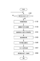
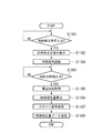
- FIG. 3 is a flowchart showing a processing procedure of time correction processing executed by the electronic device 10 in the present embodiment.
- Step S101 The user moves the electronic device 10 and the electronic timepiece 20 so that the electronic device 10 can capture an image of the display unit 208 of the electronic timepiece 20. Thereafter, the user operates the input unit 106 of the electronic device 10 to input a time correction instruction. When the input unit 106 of the electronic device 10 receives the input of the time correction instruction, the process proceeds to the process of step S102.
- Step S102 The control unit 102 controls the light source 103 and transmits a synchronization signal for a certain period. Thereafter, the process proceeds to step S103. (Step S ⁇ b> 103) After completing the transmission of the synchronization signal, the control unit 102 controls the imaging unit 104 to capture an image of the display unit 208 of the electronic timepiece 20. Thereafter, the process proceeds to step S104.
- Step S104 The control unit 102 performs image processing, and specifies the time indicated by the electronic timepiece 20 based on the captured image of the display unit 208 of the electronic timepiece 20 captured by the imaging unit 104. Thereafter, the process proceeds to step S105.
- Step S105 The time data acquisition unit 101 acquires an accurate current time. Thereafter, the process proceeds to step S106.
- Step S106 The control unit 102 calculates the difference between the time indicated by the electronic timepiece 20 specified in the process of step S104 and the current time acquired by the time data acquisition unit 101 in the process of step S105, thereby A time difference of 20 is calculated. Further, the control unit 102 calculates an amount of driving the pointer 2082 of the electronic timepiece 20 in order to eliminate the time lag of the electronic timepiece 20. That is, an amount for driving the stepping motor 207 is calculated.
- the amount of driving the stepping motor 207 of the electronic timepiece 20 is defined as a time correction amount. For example, it is assumed that the pointer 2082 advances by 1 second when the stepping motor 207 operates in one step. In this case, when the time displayed on the display unit 208 of the electronic timepiece 20 is delayed by 10 seconds, the time correction amount is “10”. Data indicating the time correction amount is set as time correction amount data. Thereafter, the process proceeds to step S107.
- Step S107 The control unit 102 controls the light source 103 and transmits a start signal. Thereafter, the process proceeds to step S108.
- Step S108 The control unit 102 controls the light source 103 and transmits time correction amount data. Thereafter, the process ends.
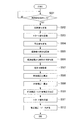
- FIG. 4 is a flowchart showing a processing procedure of time correction processing executed by the electronic timepiece 20 according to the present embodiment.
- the control circuit 202 controls the switch 203, and controls the transition between the communication period and the charging period at regular intervals. If the control circuit 202 determines that the synchronization signal has been received via the solar cell 201 during the communication period, the control circuit 202 proceeds to the process of step S202.
- Step S202 The control circuit 202 sets the communication period without switching the switch 203 from the OFF state. During the communication period, the control circuit 202 receives a start signal and time correction amount data via the solar cell 201. Thereafter, the process proceeds to step S203. (Step S203) The control circuit 202 turns on the switch 203 and shifts to the charging period. Thereafter, the process proceeds to step S204.
- Step S204 The control circuit 202 sets the time correction amount based on the time correction amount data received in the process of step S202. Thereafter, the process proceeds to step S205.
- Step S205 The control circuit 202 drives the stepping motor 207 by one step. Thereafter, the process proceeds to step S206.
- Step S206 The control circuit 202 subtracts 1 from the set time correction amount, and sets the value after subtraction as the time correction amount. Thereafter, the process proceeds to step S207.
- Step S207 The control circuit 202 determines whether or not the set time correction amount is zero. The control circuit 202 ends the process when the set time correction amount is 0, and otherwise returns to the process of step S205.
- the electronic device 10 images the display unit 208 of the electronic timepiece 20 and specifies the time indicated by the electronic timepiece 20 based on the captured image.
- the electronic device 10 calculates a time correction amount based on the difference between the current time and the time indicated by the electronic timepiece 20, and transmits the calculated time correction amount to the electronic timepiece 20.
- the electronic timepiece 20 corrects the time indicated by the display unit 208 based on the received time correction amount. Accordingly, the time indicated by the electronic timepiece 20 can be corrected to the correct time more accurately and easily without the user operating the electronic timepiece 20.
- the electronic device 10 and the electronic timepiece 20 transmit and receive the time correction amount by the optical communication method described above, a connector for connecting the electronic device 10 and the electronic timepiece 20 with a wire and an antenna for wireless communication are electronically connected. There is no need to mount it on the device 10 or the electronic timepiece 20. That is, since the electronic device 10 can communicate with the light source 103 and the electronic timepiece 20 as standard equipment such as the solar battery 201, the design of the electronic device 10 and the electronic timepiece 20 is not impaired by mounting a new device.
- the receiving electronic timepiece 20 receives the time correction amount and charges the solar cell 201 by the light emitted from the light source 103 (transmission unit) of the electronic device 10 that transmits the time correction amount. Is possible. Therefore, it is possible to charge and receive the electronic timepiece 20 simply by including the light source 103 (transmission unit) in the electronic device 10. Therefore, in the present embodiment, the electronic timepiece 20 can receive the time correction amount and charge the solar cell 201 without adopting a complicated configuration, and can further use the power of the charged solar cell 201. Therefore, the time indicated by the display unit 208 can be corrected, so that the time can be corrected stably and continuously.
- the configuration of the time correction system 1 in the present embodiment is the same as that of the first embodiment shown in FIG.
- the optical communication method of the time adjustment system 1 in the present embodiment is the same as the optical communication method shown in FIG.
- the present embodiment differs from the first embodiment in that the electronic timepiece 20 stops timing when correcting the time.
- the control unit 102 stop unit of the electronic device 10 transmits a stop signal to the electronic timepiece 20 before the imaging unit 104 images the display unit 208 of the electronic timepiece 20 to measure the time of the electronic timepiece 20. (Driving of the pointer 2082 and internal timing) are stopped. Then, the control unit 102 (additional correction amount calculation unit) calculates a time correction amount, and calculates an additional correction amount according to the time required for correction in the electronic timepiece 20 based on the calculated time correction amount.
- the additional correction amount is an amount for driving the stepping motor 207 of the electronic timepiece 20 corresponding to the time required for correcting the time in the electronic timepiece 20.
- the additional correction amount increases as the time correction amount increases, and decreases as the time correction amount decreases.
- control unit 102 outputs time correction amount data obtained by adding the additional correction amount to the time correction amount as an optical signal using the light source 103. Since the other configuration of the electronic device 10 is the same as that of the first embodiment, the description thereof is omitted.
- the control circuit 202 of the electronic timepiece 20 When the control circuit 202 of the electronic timepiece 20 receives a stop signal from the electronic device 10, the control circuit 202 stops timekeeping (driving the pointer 2082 and timekeeping inside). Thereafter, the control circuit 202 turns off the switch 203 and shifts to the communication period.
- the control circuit 202 drives the stepping motor 207 based on the received time correction amount data, corrects the time indicated by the pointer 2082, and measures the time (the driving of the pointer 2082 and the internal time). Restart (timekeeping). Since the other structure of the electronic timepiece 20 is the same as that of the first embodiment, the description thereof is omitted.
- FIG. 5 is a flowchart showing a processing procedure of time correction processing executed by the electronic apparatus 10 according to the present embodiment.
- Step S501 The user moves the electronic device 10 and the electronic timepiece 20 so that the electronic device 10 can capture an image of the display unit 208 of the electronic timepiece 20. Thereafter, the user operates the input unit 106 of the electronic device 10 to input a time correction instruction. When the input unit 106 of the electronic device 10 receives an input of a time correction instruction, the input unit 106 proceeds to the process of step S502.
- Step S502 The control unit 102 controls the light source 103 and transmits a synchronization signal for a certain period. Thereafter, the process proceeds to step S503.
- Step S503 After completing the transmission of the synchronization signal, the control unit 102 controls the light source 103 and transmits a start signal. Thereafter, the process proceeds to step S504.
- Step S504 The control unit 102 controls the light source 103 and transmits a stop signal. Thereafter, the process proceeds to step S505.
- Step S505 The control unit 102 controls the imaging unit 104 to capture an image of the display unit 208 of the electronic timepiece 20. Thereafter, the process proceeds to step S506.
- Step S506 The control unit 102 performs image processing, and specifies the time indicated by the electronic timepiece 20 based on the captured image of the display unit 208 of the electronic timepiece 20 captured by the imaging unit 104. Thereafter, the process proceeds to step S507.
- Step S507 The time data acquisition unit 101 acquires an accurate current time. Thereafter, the process proceeds to step S508.
- Step S508 The control unit 102 calculates a time correction amount based on the time indicated by the electronic timepiece 20 specified in the process of step S506 and the current time acquired by the time data acquisition unit 101 in the process of step S507. Thereafter, the process proceeds to step S509.
- Step S509 The control unit 102 calculates an additional correction amount based on the time correction amount calculated in the process of step S508. Thereafter, the process proceeds to step S510.
- Step S510 The control unit 102 adds the additional correction amount calculated in the process of step S509 to the time correction amount calculated in the process of step S508. Thereafter, the process proceeds to step S511.
- Step S511 The control unit 102 controls the light source 103 and transmits a start signal. Thereafter, the process proceeds to step S512.
- Step S512 The control unit 102 controls the light source 103 and transmits time correction amount data. Thereafter, the process ends.
- FIG. 6 is a flowchart showing a processing procedure of time correction processing executed by the electronic timepiece 20 according to the present embodiment.
- the control circuit 202 controls the switch 203, and controls the transition between the communication period and the charging period at regular intervals. If the control circuit 202 determines that the synchronization signal has been received via the solar cell 201 during the communication period, the control circuit 202 proceeds to the process of step S602.
- Step S602 The control circuit 202 sets the communication period without switching the switch 203 from the OFF state. During the communication period, the control circuit 202 receives a start signal and a stop signal via the solar cell 201. Thereafter, the process proceeds to step S603. (Step S603) The control circuit 202 stops timing. Thereafter, the process proceeds to step S604.
- Step S604 The control circuit 202 receives a start signal and time correction amount data via the solar cell 201. Thereafter, the process proceeds to step S605. (Step S605) The control circuit 202 turns on the switch 203 and shifts to the charging period. Thereafter, the process proceeds to step S606.
- Step S606 The control circuit 202 sets the time correction amount based on the time correction amount data received in the process of step S604. Thereafter, the process proceeds to step S607.
- Step S607 The control circuit 202 drives the stepping motor 207 by one step. Thereafter, the process proceeds to step S608.
- Step S608 The control circuit 202 subtracts 1 from the set time correction amount, and sets the value after subtraction as the time correction amount. Thereafter, the process proceeds to step S609.
- Step S609 The control circuit 202 determines whether or not the set time correction amount is zero. The control circuit 202 proceeds to the process of step S610 if the set time correction amount is 0, and returns to the process of step S607 otherwise. (Step S610) The control circuit 202 resumes timing. Thereafter, the process ends.
- the electronic device 10 stops the timekeeping of the electronic timepiece 20 before imaging the display unit 208 of the electronic timepiece 20.
- the electronic device 10 calculates an additional correction amount based on the calculated time correction amount, and transmits time correction amount data obtained by adding the additional correction amount to the time correction amount to the electronic timepiece 20.
- the electronic timepiece 20 corrects the time based on the received time correction amount data and restarts the time measurement. That is, since the electronic device 10 and the electronic timepiece 20 correct the time in consideration of the time required to correct the time, the time can be corrected more accurately in addition to the effects of the first embodiment.
- the configuration of the time correction system 1 in the present embodiment is the same as that of the first embodiment shown in FIG.
- the optical communication method of the time adjustment system 1 in the present embodiment is the same as the optical communication method shown in FIG.
- the present embodiment differs from the first embodiment in that the electronic timepiece 20 stops timing when correcting the time.
- the timekeeping of the electronic timepiece 20 is stopped by the stop signal.
- the timekeeping of the electronic timepiece 20 is stopped by an input from the user.
- the control unit 102 (stop unit) of the electronic device 10 instructs to stop the timekeeping of the electronic timepiece 20 (the driving of the pointer 2082 and the internal timekeeping) before the imaging unit 104 images the display unit 208 of the electronic timepiece 20. For example, “Please stop the clock” is displayed on the display unit 105.
- the user operates the input unit 210 of the electronic timepiece 20 according to the display to stop the timekeeping of the electronic timepiece 20 (driving of the hands 2082 and internal timekeeping). Then, the control unit 102 calculates a time correction amount, and calculates an additional correction amount based on the calculated time correction amount.
- control unit 102 outputs time correction amount data obtained by adding the additional correction amount to the time correction amount as an optical signal using the light source 103. Since the other configuration of the electronic device 10 is the same as that of the first embodiment, the description thereof is omitted.
- the input unit 210 of the electronic timepiece 20 receives an operation input for stopping timing (driving of the pointer 2082 and internal timing).
- the control circuit 202 of the electronic timepiece 20 stops the timekeeping (the driving of the pointer 2082 and the internal timekeeping). Thereafter, the control circuit 202 turns off the switch 203 and shifts to the communication period.
- the control circuit 202 drives the stepping motor 207 based on the received time correction amount data, corrects the time indicated by the pointer 2082, and measures the time (the driving of the pointer 2082 and the internal time). Restart (timekeeping). Since the other structure of the electronic timepiece 20 is the same as that of the first embodiment, the description thereof is omitted.
- FIG. 7 is a flowchart showing a processing procedure of time correction processing executed by the electronic apparatus 10 according to the present embodiment.
- Step S701 The user moves the electronic device 10 and the electronic timepiece 20 so that the electronic device 10 can capture an image of the display unit 208 of the electronic timepiece 20. Thereafter, the user operates the input unit 106 of the electronic device 10 to input a time correction instruction. When the input unit 106 of the electronic device 10 receives the input of the time correction instruction, the process proceeds to the process of step S702.
- Step S ⁇ b> 702 The control unit 102 displays an instruction to stop timing of the electronic timepiece 20 on the display unit 105. Thereafter, the process proceeds to step S703. (Step S703) The control unit 102 controls the light source 103 and transmits a synchronization signal for a certain period. Thereafter, the process proceeds to step S704.
- Step S704 After completing the transmission of the synchronization signal, the control unit 102 controls the imaging unit 104 to capture an image of the display unit 208 of the electronic timepiece 20. Thereafter, the process proceeds to step S705.
- Step S705 The control unit 102 performs image processing, and specifies the time indicated by the electronic timepiece 20 based on the captured image of the display unit 208 of the electronic timepiece 20 captured by the imaging unit 104. Thereafter, the process proceeds to step S706.
- Step S706 The time data acquisition unit 101 acquires an accurate current time. Thereafter, the process proceeds to step S707.
- Step S707 The control unit 102 calculates a time correction amount based on the time indicated by the electronic timepiece 20 specified in the process of step S705 and the current time acquired by the time data acquisition unit 101 in the process of step S706. Thereafter, the process proceeds to step S708.
- Step S708 The control unit 102 calculates an additional correction amount based on the time correction amount calculated in the process of step S707. Thereafter, the process proceeds to step S709.
- Step S709 The control unit 102 adds the additional correction amount calculated in the process of step S708 to the time correction amount calculated in the process of step S707. Thereafter, the process proceeds to step S710.
- Step S710 The control unit 102 controls the light source 103 and transmits a start signal. Thereafter, the process proceeds to step S711.
- Step S711 The control unit 102 controls the light source 103 and transmits time correction amount data. Thereafter, the process ends.
- FIG. 8 is a flowchart showing a processing procedure of time correction processing executed by the electronic timepiece 20 according to the present embodiment.
- the control circuit 202 controls the switch 203 to control the transition between the communication period and the charging period at regular intervals.
- the electronic device 10 displays an instruction to stop timing of the electronic timepiece 20 in the process of step S702 described above, the user operates the input unit 210 of the electronic timepiece 20 to input a timing stop instruction.
- the process proceeds to step S802.
- Step S802 The control circuit 202 stops timing. Thereafter, the process proceeds to step S803.
- Step S803 The control circuit 202 turns off the switch 203 and shifts to the communication period. If the control circuit 202 determines that the synchronization signal has been received via the solar cell 201 during the communication period, the control circuit 202 proceeds to the process of step S804.
- Step S804 The control circuit 202 receives a start signal and time correction amount data via the solar cell 201. Thereafter, the process proceeds to step S805. (Step S805) The control circuit 202 turns on the switch 203 and shifts to the charging period. Thereafter, the process proceeds to step S806.
- Step S806 The control circuit 202 sets a time correction amount based on the time correction amount data received in the process of step S804. Thereafter, the process proceeds to step S807.
- Step S807 The control circuit 202 drives the stepping motor 207 by one step. Thereafter, the process proceeds to step S808.
- Step S808 The control circuit 202 subtracts 1 from the set time correction amount, and sets the value after subtraction as the time correction amount. Thereafter, the process proceeds to step S809.
- Step S809 The control circuit 202 determines whether or not the set time correction amount is zero.
- the control circuit 202 proceeds to the process of step S810 when the set time correction amount is 0, and returns to the process of step S807 otherwise.
- Step S810 The control circuit 202 resumes timing. Thereafter, the process ends.
- the electronic device 10 stops the timekeeping of the electronic timepiece 20 before imaging the display unit 208 of the electronic timepiece 20.
- the electronic device 10 calculates an additional correction amount based on the calculated time correction amount, and transmits time correction amount data obtained by adding the additional correction amount to the time correction amount to the electronic timepiece 20.
- the electronic timepiece 20 corrects the time based on the received time correction amount data and restarts the time measurement. That is, since the electronic device 10 and the electronic timepiece 20 correct the time in consideration of the time required to correct the time, the time can be corrected more accurately in addition to the effects of the first embodiment.
- FIG. 9 is a schematic diagram illustrating the configuration of the time correction system 2 according to the present embodiment.
- the time adjustment system 2 includes an electronic device 30 and an electronic timepiece 20.
- the electronic device 30 is an electronic device such as a smartphone, a mobile phone, or a tablet terminal.
- the electronic device 30 includes a time data acquisition unit 101, a control unit 102, a light source 103, a display unit 105, and an input unit 106.
- the time data acquisition unit 101 acquires the current time (hour minute second). For example, the time data acquisition unit 101 obtains the current time by accessing a time server on the Internet, the method of acquiring the current time using GPS (Global Positioning System), and the control signal from the base station. A method for obtaining the current time is used. Note that any method may be used to acquire the current time.
- GPS Global Positioning System
- the control unit 102 controls each unit included in the electronic device 30.
- the control unit 102 (stop unit) displays an instruction (for example, “Please stop the clock”) for stopping the timekeeping of the electronic timepiece 20 (drive of the hands 2082) on the display unit 105. Timekeeping of the timepiece 20 (driving of the pointer 2082) is stopped.
- the control unit 102 (time correction amount calculation unit) corrects the time of the electronic timepiece 20 from the difference between the time of the electronic timepiece 20 input by the input unit 106 and the current time acquired by the time data acquisition unit 101. The time correction amount is calculated.
- the control unit 102 outputs time correction amount data indicating the calculated time correction amount as an optical signal using the light source 103. At this time, the control unit 102 outputs a synchronization signal, thereafter outputs a start signal, and then outputs time correction amount data.
- the light source 103 is, for example, a flash LED (Light Emitting Diode) included in the electronic device 30 or a backlight of a liquid crystal display.
- the light source 103 operates as a transmission unit that transmits an optical signal indicating time correction amount data to the electronic timepiece 20.
- the display unit 105 is a liquid crystal display (LCD, Liquid Crystal Display) or the like, and displays information.
- the input unit 106 includes a switch and receives an input.
- the electronic clock 20 is a clock that displays the time in an analog display.
- the electronic timepiece 20 includes a solar battery 201, a control circuit 202, a switch 203, a secondary battery 204, a diode 205, a reference signal generation circuit 206, a stepping motor 207, and a display unit 208.
- the display unit 208 includes a dial plate 2081, a pointer 2082, and a date unit 2083.
- the solar cell 201 operates as a power generation unit that receives light (sun, illumination, etc.) and converts it into electric energy during the charging period. Further, the solar cell 201 performs optical communication with the electronic device 30 during the communication period, and operates as a receiving unit that receives an optical signal indicating time correction amount data from the electronic device 30.
- the charging period and the communication period will be described later.
- the control circuit 202 controls each part included in the electronic timepiece 20.
- the control circuit 202 controls charging of the secondary battery 204 by the solar battery 201.
- the control circuit 202 performs overcharge prevention control of the secondary battery 204.
- the control circuit 202 performs optical communication using the solar cell 201.
- the control circuit 202 operates with electric power output from the secondary battery 204 connected to the power supply terminal and the GND terminal.
- the control circuit 202 determines the charge state (full charge, overdischarge, etc.) of the secondary battery 204 by detecting the output voltage of the secondary battery 204, and performs predetermined charge control.
- control circuit 202 performs on / off control of the switch 203 by a control signal output from the control terminal in accordance with the state of charge of the secondary battery 204. Accordingly, the control circuit 202 charges the secondary battery 204 by connecting the solar battery 201 and the secondary battery 204. In addition, the control circuit 202 prevents the secondary battery 204 from being overcharged by disconnecting the solar battery 201 and the secondary battery 204.
- control circuit 202 outputs a switch control signal based on the reference signal output from the reference signal generation circuit 206, and performs on / off control of the switch 203.
- control circuit 202 connects the solar battery 201 and the secondary battery 204 and disconnects the solar battery 201 and the secondary battery 204.
- the control circuit 202 stops the time measurement (drive of the pointer 2082). Thereafter, the control circuit 202 turns off the switch 203 and shifts to the communication period.
- control circuit 202 detects the output voltage of the solar cell 201 input to the input terminal during the communication period, and converts the detected voltage into an electric signal, so that the external device (in this embodiment) The time correction amount data transmitted from the electronic device 30) by optical communication is received.
- the control circuit 202 turns on the switch 203 and shifts to the charging period.
- the control circuit 202 drives the stepping motor 207 based on the received time correction amount data, corrects the time indicated by the pointer 2082, and restarts time measurement (drive of the pointer 2082).
- the switch 203 connects the solar battery 201 and the secondary battery 204 and disconnects the solar battery 201 and the secondary battery 204 based on a switch control signal input from the control circuit 202.
- the secondary battery 204 supplies power to each unit included in the electronic timepiece 20.
- the diode 205 prevents current from flowing backward to the secondary battery 204.
- the reference signal generation circuit 206 includes an oscillation circuit (for example, 32 kHz) and a frequency dividing circuit, and generates a reference signal of 1 Hz, for example.
- the stepping motor 207 drives (rotates) the pointer 2082 and the date portion 2083 based on the pulse signal input from the control circuit 202.
- the display unit 208 displays time and date in an analog display using a dial plate 2081, a pointer 2082, and a date unit 2083.
- the display unit 208 indicates the time by a dial plate 2081 and a pointer 2082, and indicates the date by a date unit 2083.
- the storage unit 209 is a nonvolatile memory, for example, and stores data used by each unit included in the electronic timepiece 20.
- the input unit 210 receives an operation input input by a user. For example, the input unit 210 receives an operation input for stopping timing (driving the pointer 2082).
- the electronic device 30 transmits data using the light source 103.
- the electronic device 30 causes the light source 103 to emit light when transmitting “1”, and turns off the light source 103 when transmitting “0”.
- the electronic timepiece 20 receives data using the solar cell 201.
- the control circuit 202 of the electronic timepiece 20 determines that “1” is received when the solar cell 201 receives light and generates a voltage, and “0” when the solar cell 201 does not generate a voltage. "Is received.
- the switch 203 is controlled to disconnect the solar battery 201 and the secondary battery 204 in order to detect the voltage generated by the solar battery 201 with higher accuracy.
- a period during which the solar battery 201 and the secondary battery 204 are disconnected is referred to as a “communication period (OFF period)”.
- the switch 203 is controlled to connect the solar battery 201 and the secondary battery 204.
- a period in which the solar battery 201 and the secondary battery 204 are connected is referred to as a “charging period (ON period)”. Thereby, data can be received with higher accuracy during the reception period.
- the electronic timepiece 20 is normally set as a charging period, and a short communication period is provided for each fixed period. If the electronic timepiece 20 receives a synchronization signal from the electronic device 30 during a short communication period, the electronic timepiece 20 continues the communication period until time correction amount data is received. On the other hand, when the electronic timepiece 20 does not receive the synchronization signal from the electronic device 30 during the communication period, the electronic timepiece 20 is set to the charging period.
- the optical communication method of the time adjustment system 2 in the present embodiment is the same as the optical communication method shown in FIG. That is, also in the present embodiment, as in the first embodiment, the electronic timepiece 20 repeats a charging period and a communication period shorter than the charging period. When a synchronization signal is received during a short communication period, the communication period is set until reception of time correction amount data is completed. Thereby, the electronic timepiece 20 can receive the optical signal with higher accuracy while extending the charging period.
- FIG. 10 is a flowchart showing a processing procedure of time correction processing executed by the electronic device 30 in the present embodiment.
- Step S1101 The user operates the input unit 106 of the electronic device 30 to input a time correction instruction.
- the process proceeds to the process of step S1102.
- Step S ⁇ b> 1102 The control unit 102 displays an instruction to stop the timekeeping of the electronic timepiece 20 on the display unit 105. Thereafter, the process proceeds to step S1103. (Step S1103) The control unit 102 controls the light source 103 and transmits a synchronization signal for a certain period. Thereafter, the process proceeds to step S1104.
- Step S1104 After completing the transmission of the synchronization signal, the control unit 102 receives an input of the time indicated by the pointer 2082 of the electronic timepiece 20 by the input unit 106. The user operates the input unit 106 to input the time indicated by the pointer 2082 of the electronic timepiece 20. When the input unit 106 of the electronic device 30 accepts the input of the time indicated by the electronic timepiece 20, the process proceeds to step S1105.
- Step S1105 The time data acquisition unit 101 acquires an accurate current time. Thereafter, the process proceeds to step S1106.
- Step S1106 The control unit 102 calculates the difference between the time indicated by the electronic timepiece 20 input in the process of step S1104 and the current time acquired by the time data acquisition unit 101 in the process of step S1105.
- the time lag of the clock 20 is calculated.
- the control unit 102 calculates an amount of driving the pointer 2082 of the electronic timepiece 20 in order to eliminate the time lag of the electronic timepiece 20. That is, an amount for driving the stepping motor 207 is calculated.
- the amount of driving the stepping motor 207 of the electronic timepiece 20 is defined as a time correction amount.
- the pointer 2082 advances by 1 second when the stepping motor 207 operates in one step.
- the time correction amount is “10”.
- Data indicating the time correction amount is set as time correction amount data. Thereafter, the process proceeds to step S1107.
- Step S1107 The control unit 102 controls the light source 103 and transmits a start signal. Thereafter, the process proceeds to step S1108.
- Step S1108 The control unit 102 controls the light source 103 and transmits time correction amount data. Thereafter, the process ends.
- FIG. 11 is a flowchart showing a processing procedure of time correction processing executed by the electronic timepiece 20 according to the present embodiment.
- the control circuit 202 controls the switch 203, and controls the transition between the communication period and the charging period at regular intervals.
- the electronic device 30 displays an instruction to stop timing of the electronic timepiece 20 in the process of step S1102 described above, the user operates the input unit 210 of the electronic timepiece 20 to input a timing stop instruction.
- the process proceeds to step S1202.
- Step S1202 The control circuit 202 stops timing. Thereafter, the process proceeds to step S1203.
- Step S1203 The control circuit 202 turns off the switch 203 and shifts to the communication period. Thereafter, the process proceeds to step S1204.
- Step S1204 The control circuit 202 determines whether or not a synchronization signal has been received via the solar cell 201. If it is determined that the synchronization signal has been received, the control circuit 202 proceeds to the process of step S1205, and otherwise returns to the process of step S1204. (Step S1205) The control circuit 202 receives the start signal and the time correction amount data via the solar cell 201. Thereafter, the process proceeds to step S1206. (Step S1206) The control circuit 202 turns on the switch 203 and shifts to the charging period. Thereafter, the process proceeds to step S1207.
- Step S1207 The control circuit 202 sets the time correction amount based on the time correction amount data received in the process of step S1205. Thereafter, the process proceeds to step S1208.
- Step S1208 The control circuit 202 drives the stepping motor 207 by one step. Thereafter, the process proceeds to step S1209.
- Step S1209 The control circuit 202 subtracts 1 from the set time correction amount, and sets the value after subtraction as the time correction amount. Thereafter, the process proceeds to step S1210.
- Step S1210 The control circuit 202 determines whether or not the set time correction amount is zero.
- the control circuit 202 proceeds to the process of step S1211 when the set time correction amount is 0, and returns to the process of step S1208 otherwise.
- Step S1211 The control circuit 202 resumes timing. Thereafter, the process ends.
- the electronic device 30 receives an input of the time indicated by the display unit 208 of the electronic timepiece 20, and calculates a time correction amount based on the difference between the current time and the time indicated by the electronic timepiece 20.
- the calculated time correction amount is transmitted to the electronic timepiece 20.
- the electronic timepiece 20 corrects the time indicated by the display unit 208 based on the received time correction amount. Accordingly, the time indicated by the electronic timepiece 20 can be corrected to the correct time more accurately and easily without the user operating the electronic timepiece 20.
- the electronic device 30 calculates the time correction amount, the processing load of the electronic timepiece 20 can be reduced.
- a connector for connecting the electronic device 30 and the electronic timepiece 20 with a wire and an antenna for wireless communication are electronically connected. It is not necessary to mount on the device 30 or the electronic timepiece 20. That is, since the electronic device 30 can communicate with the light source 103 and the electronic timepiece 20 as standard equipment such as the solar battery 201, the design of the electronic device 30 and the electronic timepiece 20 is not impaired by installing a new device.
- the reception-side electronic timepiece 20 receives the time correction amount and charges the solar battery 201 by the light emitted from the light source 103 (transmission unit) of the electronic device 30 that transmits the time correction amount. Is possible. Therefore, it is possible to charge and receive the electronic timepiece 20 simply by including the light source 103 (transmission unit) in the electronic device 30. Therefore, in the present embodiment, the electronic timepiece 20 can receive the time correction amount and charge the solar cell 201 without adopting a complicated configuration, and can further use the power of the charged solar cell 201. Therefore, the time indicated by the display unit 208 can be corrected, so that the time can be corrected stably and continuously.
- the configuration of the time correction system 2 in this embodiment is the same as that of the fourth embodiment shown in FIG.
- the optical communication method of the time adjustment system 2 in this embodiment is the same as the optical communication method shown in FIG.
- the timekeeping of the electronic timepiece 20 is stopped by an input from the user, but in this embodiment, the timekeeping of the electronic timepiece 20 is stopped by a stop signal from the electronic device 30.
- control unit 102 stop unit of the electronic device 30 transmits a stop signal to the electronic timepiece 20 to stop the timekeeping of the electronic timepiece 20 (drive of the pointer 2082). Since the other configuration of the electronic device 30 is the same as that of the fourth embodiment, the description thereof is omitted.
- control circuit 202 of the electronic timepiece 20 When the control circuit 202 of the electronic timepiece 20 receives a stop signal from the electronic device 30, the control circuit 202 stops timing (driving the pointer 2082). Thereafter, the control circuit 202 turns off the switch 203 and shifts to the communication period. Since the other structure of the electronic timepiece 20 is the same as that of the fourth embodiment, the description thereof is omitted.
- FIG. 12 is a flowchart showing a processing procedure of time correction processing executed by the electronic device 30 according to the present embodiment.
- Step S1301 The user operates the input unit 106 of the electronic device 30 to input a time correction instruction.
- the process proceeds to step S1302.
- Step S1302 The control unit 102 controls the light source 103 and transmits a synchronization signal for a certain period. Thereafter, the process proceeds to step S1303.
- Step S1303 After completing the transmission of the synchronization signal, the control unit 102 controls the light source 103 and transmits a start signal. Thereafter, the process proceeds to step S1304.
- Step S1304 The control unit 102 controls the light source 103 and transmits a stop signal. Thereafter, the process proceeds to step S1305.
- Step S1305 The control unit 102 receives an input of the time indicated by the hand 2082 of the electronic timepiece 20 through the input unit 106.
- the user operates the input unit 106 to input the time indicated by the pointer 2082 of the electronic timepiece 20.
- the input unit 106 of the electronic device 30 receives an input of the time indicated by the electronic timepiece 20, the process proceeds to step S1306.
- Step S1366 The time data acquisition unit 101 acquires an accurate current time. Thereafter, the process proceeds to step S1307.
- Step S1307 The control unit 102 calculates a time correction amount based on the time indicated by the electronic timepiece 20 input in the process of step S1305 and the current time acquired by the time data acquisition unit 101 in the process of step S1306. . Thereafter, the process proceeds to step S1308.
- Step S1308 The control unit 102 controls the light source 103 and transmits a start signal. Thereafter, the process proceeds to step S1309. (Step S1309) The control unit 102 controls the light source 103 and transmits time correction amount data. Thereafter, the process ends.
- the processing procedure of the time adjustment process executed by the electronic timepiece 20 in the present embodiment is the same as the processing procedure of the time adjustment process executed by the electronic timepiece 20 in the second embodiment shown in FIG. To do.
- the electronic device 30 transmits a stop signal to the electronic timepiece 20 to stop the electronic timepiece 20.
- the effort which a user stops the electronic timepiece 20 manually can be saved.
- the configuration of the time correction system 2 in this embodiment is the same as that of the fourth embodiment shown in FIG.
- the optical communication method of the time adjustment system 2 in this embodiment is the same as the optical communication method shown in FIG.
- This embodiment differs from the fourth embodiment in that the electronic device 30 adds the additional correction amount to the time correction amount and transmits the time correction amount data to the electronic timepiece 20.
- the additional correction amount is an amount for driving the stepping motor 207 of the electronic timepiece 20 corresponding to the time required for correcting the time in the electronic timepiece 20.
- the additional correction amount increases as the time correction amount increases, and decreases as the time correction amount decreases. This is because it is considered that it takes time to correct the time as the time correction amount increases.
- the control unit 102 (additional correction amount calculation unit) of the electronic device 30 calculates a time correction amount, and calculates the additional correction amount based on the calculated time correction amount. Then, the control unit 102 outputs time correction amount data obtained by adding the additional correction amount to the time correction amount as an optical signal using the light source 103. Since the other configuration of the electronic device 30 is the same as that of the fourth embodiment, the description thereof is omitted. Moreover, since the configuration of the electronic timepiece 20 is the same as that of the fourth embodiment, description thereof is omitted.
- FIG. 13 is a flowchart showing a processing procedure of time correction processing executed by the electronic device 30 according to the present embodiment.
- Step S1501 The user operates the input unit 106 of the electronic device 30 to input a time correction instruction.
- the process proceeds to step S1502.
- Step S ⁇ b> 1502 The control unit 102 displays an instruction to stop timing of the electronic timepiece 20 on the display unit 105. Thereafter, the process proceeds to step S1503. (Step S1503) The control unit 102 controls the light source 103 and transmits a synchronization signal for a certain period. Thereafter, the process proceeds to step S1504.
- Step S1504 After completing the transmission of the synchronization signal, the control unit 102 receives an input of the time indicated by the pointer 2082 of the electronic timepiece 20 by the input unit 106. The user operates the input unit 106 to input the time indicated by the pointer 2082 of the electronic timepiece 20. When the input unit 106 of the electronic device 30 receives the input of the time indicated by the electronic timepiece 20, the process proceeds to step S1505.
- Step S1505 The time data acquisition unit 101 acquires an accurate current time. Thereafter, the process proceeds to step S1506.
- Step S1506 The control unit 102 calculates a time correction amount based on the time indicated by the electronic timepiece 20 input in the process of step S1504 and the current time acquired by the time data acquisition unit 101 in the process of step S1505. . Thereafter, the process proceeds to step S1507.
- Step S1507 The control unit 102 calculates an additional correction amount based on the time correction amount calculated in the process of step S1506. Thereafter, the process proceeds to step S1508.
- Step S1508 The control unit 102 adds the additional correction amount calculated in step S1507 to the time correction amount calculated in step S1506. Thereafter, the process proceeds to step S1509.
- Step S1509 The control unit 102 controls the light source 103 and transmits a start signal. Thereafter, the process proceeds to step S1510.
- Step S1510 The control unit 102 controls the light source 103 and transmits time correction amount data. Thereafter, the process ends.
- the processing procedure of the time correction process executed by the electronic timepiece 20 in the present embodiment is the same as the processing procedure of the time correction process executed by the electronic timepiece 20 in the fourth embodiment shown in FIG. To do.
- the electronic device 30 calculates the additional correction amount based on the calculated time correction amount, and transmits the time correction amount data obtained by adding the additional correction amount to the time correction amount to the electronic timepiece 20. That is, since the electronic device 30 and the electronic timepiece 20 correct the time in consideration of the time required for correcting the time, the time can be corrected more accurately in addition to the effects of the fourth embodiment.
- the configuration of the time correction system 2 in this embodiment is the same as that of the fourth embodiment shown in FIG.
- the optical communication method of the time adjustment system 2 in this embodiment is the same as the optical communication method shown in FIG.
- This embodiment is different from the fifth embodiment in that the electronic device 30 adds the additional correction amount to the time correction amount and transmits the time correction amount data to the electronic timepiece 20.
- the control unit 102 (additional correction amount calculation unit) of the electronic device 30 calculates a time correction amount, and calculates the additional correction amount based on the calculated time correction amount. Then, the control unit 102 outputs time correction amount data obtained by adding the additional correction amount to the time correction amount as an optical signal using the light source 103. Since the other configuration of the electronic device 30 is the same as that of the fifth embodiment, the description thereof is omitted. Further, since the configuration of the electronic timepiece 20 is the same as that of the fifth embodiment, the description thereof is omitted.
- FIG. 14 is a flowchart illustrating a processing procedure of time correction processing executed by the electronic device 30 according to the present embodiment.
- Step S1701 The user operates the input unit 106 of the electronic device 30 to input a time correction instruction.
- the input unit 106 of the electronic device 30 receives the input of the time correction instruction, the input unit 106 proceeds to the process of step S1702.
- Step S1702 The control unit 102 controls the light source 103 and transmits a synchronization signal for a certain period. Thereafter, the process proceeds to step S1703.
- Step S1703 After completing the transmission of the synchronization signal, the control unit 102 controls the light source 103 and transmits a start signal. Thereafter, the process proceeds to step S1704.
- Step S1704 The control unit 102 controls the light source 103 and transmits a stop signal. Thereafter, the process proceeds to step S1705.
- Step S1705 The control unit 102 receives an input of the time indicated by the pointer 2082 of the electronic timepiece 20 by the input unit 106.
- the user operates the input unit 106 to input the time indicated by the pointer 2082 of the electronic timepiece 20.
- the process proceeds to step S1706.
- Step S1706 The time data acquisition unit 101 acquires an accurate current time. Thereafter, the process proceeds to step S1707.
- Step S1707 The control unit 102 calculates a time correction amount based on the time indicated by the electronic timepiece 20 input in the process of step S1705 and the current time acquired by the time data acquisition unit 101 in the process of step S1706. . Thereafter, the process proceeds to step S1708.
- Step S1708 The control unit 102 calculates an additional correction amount based on the time correction amount calculated in the process of step S1707. Thereafter, the process proceeds to step S1709.
- Step S1709 The control unit 102 adds the additional correction amount calculated in step S1708 to the time correction amount calculated in step S1707. Thereafter, the process proceeds to step S1710.
- Step S1710 The control unit 102 controls the light source 103 and transmits a start signal. Thereafter, the process proceeds to step S1711.
- Step S1711 The control unit 102 controls the light source 103 and transmits time correction amount data. Thereafter, the process ends.
- the processing procedure of the time adjustment process executed by the electronic timepiece 20 in the present embodiment is the same as the processing procedure of the time adjustment process executed by the electronic timepiece 20 in the second embodiment shown in FIG. To do.
- the electronic device 30 calculates the additional correction amount based on the calculated time correction amount, and transmits the time correction amount data obtained by adding the additional correction amount to the time correction amount to the electronic timepiece 20. That is, since the electronic device 30 and the electronic timepiece 20 correct the time in consideration of the time required for correcting the time, in addition to the effects of the fifth embodiment, the time can be corrected more accurately.
- each part with which the electronic devices 10 and 30 and the electronic timepiece 20 in the above-described embodiment are provided or a part thereof is recorded on a computer-readable recording medium by recording a program for realizing these functions.
- the “computer system” includes an OS and hardware such as peripheral devices.
- the “computer-readable recording medium” means a portable medium such as a flexible disk, a magneto-optical disk, a ROM, and a CD-ROM, and a storage unit such as a hard disk built in the computer system. Furthermore, the “computer-readable recording medium” dynamically holds a program for a short time like a communication line when transmitting a program via a network such as the Internet or a communication line such as a telephone line. In this case, a volatile memory inside a computer system serving as a server or a client in that case may be included and a program that holds a program for a certain period of time.
- the program may be a program for realizing a part of the functions described above, and may be a program capable of realizing the functions described above in combination with a program already recorded in a computer system.
- the electronic devices 10 and 30 transmit time correction amount data to the electronic timepiece 20, all the time correction amount data may be converted into second data and transmitted.
- the electronic timepiece 20 can quickly carry out the processing from the reception of the time correction amount data to the correction of the time indicated by the display unit 208.
- the electronic timepiece 20 has a separate hour / minute counter. Therefore, it is advantageous in terms of the circuit configuration of the narrow space of the electronic timepiece 20.
- the electronic timepiece 20 repeats the charging period and the communication period in which optical communication is performed at a predetermined period.
- the electronic timepiece 20 is not limited to this, and the switch The charging period and the communication period may be switched by controlling 203.
- the electronic timepiece 20 first detects a synchronization signal at a low communication rate, and after detecting the synchronization signal, switches to a high communication rate (for example, four times the low speed communication rate), May be received. Thereby, the power consumption of the electronic devices 10 and 30 and the electronic timepiece 20 can be reduced.
- the electronic timepiece 20 corrects only the time indicated by the display unit 208, but may correct the time indicated by the display unit 208 in addition to the time.
- the control unit 102 of the electronic device 10 extracts the date part 2083 from the image of the display unit 208, identifies the number displayed on the date part 2083, and specifies the date.
- the time data acquisition unit 101 acquires the current date and time (current time (hour / minute / second) and current date (year / month / day)).
- the control unit 102 calculates a date correction amount for correcting the date from the difference between the date determined based on the image on the display unit 208 and the current date acquired by the time data acquisition unit 101.
- control unit 102 transmits data indicating the time correction amount and the date correction amount to the electronic timepiece 20.
- the control circuit 202 of the electronic timepiece 20 corrects the time and date indicated by the display unit 208 based on the received time correction amount and date correction amount.
- the electronic timepiece 20 corrects only the time indicated by the display unit 208, but may correct the time indicated by the display unit 208 in addition to the time.
- the control unit 102 of the electronic device 30 specifies the date from the number displayed by the date unit 2083 of the electronic timepiece 20 input by the input unit 106.
- the time data acquisition unit 101 acquires the current date and time (current time (hour / minute / second) and current date (year / month / day)).
- the control unit 102 calculates a date correction amount for correcting the date from the difference between the date input to the input unit 106 and the current date acquired by the time data acquisition unit 101.
- control unit 102 transmits data indicating the time correction amount and the date correction amount to the electronic timepiece 20.
- the control circuit 202 of the electronic timepiece 20 corrects the time and date indicated by the display unit 208 based on the received time correction amount and date correction amount.
- the embodiment of the present invention provides a time correction system.
- the time correction system includes at least a clock and an electronic device.
- the electronic device includes at least an acquisition unit, an input unit, a time correction amount calculation unit, and a transmission unit.
- the timepiece includes at least a receiving unit, a power storage unit, a driving unit, and a control unit.
- the acquisition unit acquires a current time.
- the input unit receives an input of time indicated by the display unit of the timepiece.
- the time correction amount calculation unit calculates a time correction amount for correcting the time of the clock from a difference between a time when the input unit receives an input and a current time acquired by the acquisition unit.
- the transmission unit transmits the time correction amount calculated by the time correction amount calculation unit to the timepiece on light.
- the receiving unit receives the time correction amount from the electronic device.
- the power storage unit is stored with electric power to which the light is converted.
- the driving unit drives the pointer.
- the control unit corrects the time indicated by the pointer based on the time correction amount received by the receiving unit.
- the control unit controls a power storage period in the power storage unit and a reception period in the reception unit, and receives the time correction amount in the reception period.
- the transmission unit of the electronic device may transmit the current time together with the time correction amount.
- the receiving unit of the timepiece may receive the current time together with the time correction amount.
- the timepiece may include a timer unit that measures the current time.
- the control unit of the timepiece may correct the current time measured by the time measuring unit based on the current time received by the receiving unit.
- the electronic device may include a stop unit that stops the driving of the hands of the timepiece.
- the timepiece control unit may resume driving of the hands when the receiving unit receives the time correction amount.
- the electronic device calculates an additional correction amount according to a time required for correction in the timepiece based on the time correction amount calculated by the time correction amount calculation unit, and uses the calculated additional correction amount as the time correction amount. You may provide the additional correction amount calculation part to add.
- the stop unit of the electronic device may transmit a stop signal for stopping the driving of the hands to the watch.
- the control unit of the timepiece may stop driving the hands when receiving the stop signal.
- the electronic device may include a display unit.
- the stop unit of the electronic device may display an instruction to stop driving the pointer on the display unit.
- the timepiece may include an input unit that receives an operation input.
- the control unit of the timepiece may stop driving of the hands when the input unit receives an operation input for stopping the driving of the hands.
- the transmission unit of the electronic device may be a light source that transmits an optical signal.
- the receiving unit of the timepiece may be a solar cell that receives an optical signal.
- the input unit may include a switch. You may receive the input of the time which the said display part of the said clock shows by operation of the said switch.
- an imaging unit that images the display unit of the timepiece
- a specifying unit that specifies the time indicated by the display unit of the timepiece from an image captured by the imaging unit
- the input unit accepts input of a time indicated by the display unit of the timepiece specified by the specifying unit.
- Embodiment of this invention provides the said electronic device in the time correction system provided with the timepiece which has a display part which shows time with a pointer
- the electronic device includes at least an acquisition unit, an input unit, a time correction amount calculation unit, and a transmission unit.
- the acquisition unit acquires a current time.
- the input unit receives an input of time indicated by the display unit of the timepiece.
- the time correction amount calculation unit calculates a time correction amount for correcting the time of the clock from a difference between a time when the input unit receives an input and a current time acquired by the acquisition unit.
- the transmission unit transmits the time correction amount calculated by the time correction amount calculation unit to the timepiece on light.
- Embodiment of this invention provides the said timepiece in the time correction system provided with the timepiece which has a display part which shows time with a pointer
- the timepiece includes at least a receiving unit, a power storage unit, a driving unit, and a control unit.
- the receiving unit receives a time correction amount for correcting a time transmitted from the electronic device on light.
- the power storage unit is stored with electric power to which the light is converted.
- the driving unit drives the pointer.
- the control unit corrects the time indicated by the pointer based on the time correction amount received by the receiving unit.
- the control unit controls a power storage period in the power storage unit and a reception period in the reception unit, and receives the time correction amount in the reception period.
- An embodiment of the present invention includes an acquisition step of acquiring a current time in a computer as the electronic device in a time adjustment system including a timepiece having a display unit that indicates time by hands and an electronic device, and the display of the timepiece A time for calculating a time correction amount for correcting the time of the clock from an input step for receiving an input of time indicated by the unit, and a difference between the time at which the input is received at the input step and the current time acquired at the acquisition step There is provided a program for executing a correction amount calculation step and a transmission step of transmitting the time correction amount calculated in the time correction amount calculation step to the timepiece on light.
Landscapes
- Physics & Mathematics (AREA)
- General Physics & Mathematics (AREA)
- Engineering & Computer Science (AREA)
- Power Engineering (AREA)
- Electric Clocks (AREA)
- Electromechanical Clocks (AREA)
- Telephone Function (AREA)
Abstract
Description
本願は、2013年11月12日に、日本に出願された特願2013-234254および特願2013-234255に基づき優先権を主張し、その内容をここに援用する。
まず、本発明の第1の実施形態について説明する。図1は、本実施形態による時刻修正システム1の構成を示した概略図である。図示する例では、時刻修正システム1は、電子機器10と電子時計20とを含んでいる。電子機器10は、例えば、スマートフォンや、携帯電話機や、タブレット端末等の電子機器である。図示する例では、電子機器10は、時刻データ取得部101と、制御部102と、光源103と、撮像部104と、表示部105と、入力部106とを備えている。
(ステップS103)制御部102は、同期信号の送信を完了した後、撮像部104を制御し、電子時計20の表示部208の画像を撮像する。その後、ステップS104の処理に進む。
(ステップS108)制御部102は、光源103を制御し、時刻補正量データを送信する。その後、処理を終了する。
(ステップS201)制御回路202は、スイッチ203を制御し、一定期間毎に通信期間と充電期間との移行を制御する。制御回路202は、通信期間中に、太陽電池201を介して同期信号を受信したと判定した場合、ステップS202の処理に進む。
(ステップS203)制御回路202は、スイッチ203をONの状態とし、充電期間に移行する。その後、ステップS204の処理に進む。
(ステップS205)制御回路202は、ステッピングモータ207を1ステップ駆動する。その後、ステップS206の処理に進む。
次に、本発明の第2の実施形態について説明する。本実施形態における時刻修正システム1の構成は、図1に示す第1の実施形態と同様である。また、本実施形態における時刻修正システム1の光通信方法は、図2に示す光通信方法と同様である。本実施形態と第1の実施形態とは、時刻を修正する際に、電子時計20が計時を停止する点で異なる。
(ステップS503)制御部102は、同期信号の送信を完了した後、光源103を制御し、スタート信号を送信する。その後、ステップS504の処理に進む。
(ステップS504)制御部102は、光源103を制御し、停止信号を送信する。その後、ステップS505の処理に進む。
(ステップS510)制御部102は、ステップS508の処理で算出した時刻補正量に、ステップS509の処理で算出した付加補正量を加算する。その後、ステップS511の処理に進む。
(ステップS512)制御部102は、光源103を制御し、時刻補正量データを送信する。その後、処理を終了する。
(ステップS601)制御回路202は、スイッチ203を制御し、一定期間毎に通信期間と充電期間との移行を制御する。制御回路202は、通信期間中に、太陽電池201を介して同期信号を受信したと判定した場合、ステップS602の処理に進む。
(ステップS603)制御回路202は、計時を停止する。その後、ステップS604の処理に進む。
(ステップS605)制御回路202は、スイッチ203をONの状態とし、充電期間に移行する。その後、ステップS606の処理に進む。
(ステップS607)制御回路202は、ステッピングモータ207を1ステップ駆動する。その後、ステップS608の処理に進む。
(ステップS610)制御回路202は、計時を再開する。その後、処理を終了する。
次に、本発明の第3の実施形態について説明する。本実施形態における時刻修正システム1の構成は、図1に示す第1の実施形態と同様である。また、本実施形態における時刻修正システム1の光通信方法は、図2に示す光通信方法と同様である。本実施形態と第1の実施形態とは、時刻を修正する際に、電子時計20が計時を停止する点で異なる。上述した第2の実施形態では、停止信号により電子時計20の計時を停止しているが、本実施形態では、ユーザからの入力により電子時計20の計時を停止する。
(ステップS703)制御部102は、光源103を制御し、一定期間、同期信号を送信する。その後、ステップS704の処理に進む。
(ステップS709)制御部102は、ステップS707の処理で算出した時刻補正量に、ステップS708の処理で算出した付加補正量を加算する。その後、ステップS710の処理に進む。
(ステップS711)制御部102は、光源103を制御し、時刻補正量データを送信する。その後、処理を終了する。
(ステップS801)制御回路202は、スイッチ203を制御し、一定期間毎に通信期間と充電期間との移行を制御する。ユーザは、上述したステップS702の処理で電子機器10が電子時計20の計時を停止する指示を表示すると、電子時計20の入力部210を操作し、計時停止指示の入力を行う。電子時計20の入力部210は、計時停止指示の入力を受け付けた場合、ステップS802の処理に進む。
(ステップS803)制御回路202は、スイッチ203をOFFの状態とし、通信期間に移行する。制御回路202は、通信期間中に、太陽電池201を介して同期信号を受信したと判定した場合、ステップS804の処理に進む。
(ステップS805)制御回路202は、スイッチ203をONの状態とし、充電期間に移行する。その後、ステップS806の処理に進む。
(ステップS807)制御回路202は、ステッピングモータ207を1ステップ駆動する。その後、ステップS808の処理に進む。
(ステップS810)制御回路202は、計時を再開する。その後、処理を終了する。
次に、本発明の第4の実施形態について説明する。図9は、本実施形態による時刻修正システム2の構成を示した概略図である。図示する例では、時刻修正システム2は、電子機器30と電子時計20とを含んでいる。電子機器30は、例えば、スマートフォンや、携帯電話機や、タブレット端末等の電子機器である。図示する例では、電子機器30は、時刻データ取得部101と、制御部102と、光源103と、表示部105と、入力部106とを備えている。
(ステップS1103)制御部102は、光源103を制御し、一定期間、同期信号を送信する。その後、ステップS1104の処理に進む。
(ステップS1108)制御部102は、光源103を制御し、時刻補正量データを送信する。その後、処理を終了する。
(ステップS1201)制御回路202は、スイッチ203を制御し、一定期間毎に通信期間と充電期間との移行を制御する。ユーザは、上述したステップS1102の処理で電子機器30が電子時計20の計時を停止する指示を表示すると、電子時計20の入力部210を操作し、計時停止指示の入力を行う。電子時計20の入力部210は、計時停止指示の入力を受け付けた場合、ステップS1202の処理に進む。
(ステップS1203)制御回路202は、スイッチ203をOFFの状態とし、通信期間に移行する。その後、ステップS1204の処理に進む。
(ステップS1205)制御回路202は、太陽電池201を介してスタート信号と時刻補正量データとを受信する。その後、ステップS1206の処理に進む。
(ステップS1206)制御回路202は、スイッチ203をONの状態とし、充電期間に移行する。その後、ステップS1207の処理に進む。
(ステップS1208)制御回路202は、ステッピングモータ207を1ステップ駆動する。その後、ステップS1209の処理に進む。
(ステップS1211)制御回路202は、計時を再開する。その後、処理を終了する。
次に、本発明の第5の実施形態について説明する。本実施形態における時刻修正システム2の構成は、図9に示す第4の実施形態と同様である。また、本実施形態における時刻修正システム2の光通信方法は、図2に示す光通信方法と同様である。第4の実施形態では、ユーザからの入力により電子時計20の計時を停止しているが、本実施形態では、電子機器30からの停止信号により電子時計20の計時を停止する。
(ステップS1303)制御部102は、同期信号の送信を完了した後、光源103を制御し、スタート信号を送信する。その後、ステップS1304の処理に進む。
(ステップS1304)制御部102は、光源103を制御し、停止信号を送信する。その後、ステップS1305の処理に進む。
(ステップS1309)制御部102は、光源103を制御し、時刻補正量データを送信する。その後、処理を終了する。
次に、本発明の第6の実施形態について説明する。本実施形態における時刻修正システム2の構成は、図9に示す第4の実施形態と同様である。また、本実施形態における時刻修正システム2の光通信方法は、図2に示す光通信方法と同様である。本実施形態と第4の実施形態とは、電子機器30が時刻補正量に付加補正量を加算して、時刻補正量データを電子時計20に送信する点で異なる。付加補正量とは、電子時計20において時刻を修正するために要する時間に対応する、電子時計20のステッピングモータ207を駆動する量である。付加補正量は、時刻補正量が大きいほど大きく、時刻補正量が小さいほど小さい。これは、時刻補正量が大きいほど時刻を修正するために時間を要すると考えられるためである。
(ステップS1503)制御部102は、光源103を制御し、一定期間、同期信号を送信する。その後、ステップS1504の処理に進む。
(ステップS1508)制御部102は、ステップS1506の処理で算出した時刻補正量に、ステップS1507の処理で算出した付加補正量を加算する。その後、ステップS1509の処理に進む。
(ステップS1510)制御部102は、光源103を制御し、時刻補正量データを送信する。その後、処理を終了する。
次に、本発明の第7の実施形態について説明する。本実施形態における時刻修正システム2の構成は、図9に示す第4の実施形態と同様である。また、本実施形態における時刻修正システム2の光通信方法は、図2に示す光通信方法と同様である。本実施形態は、第5の実施形態に対して、電子機器30が時刻補正量に付加補正量を加算して、時刻補正量データを電子時計20に送信する点で異なる。
(ステップS1703)制御部102は、同期信号の送信を完了した後、光源103を制御し、スタート信号を送信する。その後、ステップS1704の処理に進む。
(ステップS1704)制御部102は、光源103を制御し、停止信号を送信する。その後、ステップS1705の処理に進む。
(ステップS1709)制御部102は、ステップS1707の処理で算出した時刻補正量に、ステップS1708の処理で算出した付加補正量を加算する。その後、ステップS1710の処理に進む。
(ステップS1711)制御部102は、光源103を制御し、時刻補正量データを送信する。その後、処理を終了する。
Claims (12)
- 指針により時刻を示す表示部を有する時計と、電子機器とを備える時刻修正システムであって、
前記電子機器は、
現在時刻を取得する取得部と、
前記時計の前記表示部が示す時刻の入力を受け付ける入力部と、
前記入力部が入力を受け付けた時刻と前記取得部が取得した現在時刻との差分から前記時計の時刻を補正するための時刻補正量を算出する時刻補正量算出部と、
前記時刻補正量算出部が算出した前記時刻補正量を光にのせて前記時計に送信する送信部と、
を備え、
前記時計は、
前記電子機器から前記時刻補正量を受信する受信部と、
前記光が変換される電力により蓄電される蓄電部と、
前記指針を駆動する駆動部と、
前記受信部が受信した前記時刻補正量に基づいて前記指針が示す時刻を修正する制御部と、
を備え、
前記制御部は、前記蓄電部における蓄電期間と前記受信部における受信期間とを制御し、前記受信期間において前記時刻補正量を受信する
ことを特徴とする時刻修正システム。 - 前記電子機器の前記送信部は、前記時刻補正量とともに前記現在時刻を送信し、
前記時計の前記受信部は、前記時刻補正量とともに前記現在時刻を受信し、
前記時計は、現在時刻を計時する計時部を備え、
前記時計の前記制御部は、前記受信部が受信した現在時刻に基づいて、前記計時部が計時する現在時刻を修正する
ことを特徴とする請求項1に記載の時刻修正システム。 - 前記電子機器は、前記時計の前記指針の駆動を停止させる停止部を備え、
前記時計の制御部は、前記受信部が前記時刻補正量を受信すると、前記指針の駆動を再開する
ことを特徴とする請求項1または2に記載の時刻修正システム。 - 前記電子機器は、
前記時刻補正量算出部が算出した前記時刻補正量に基づいて、前記時計において修正に要する時間に応じた付加補正量を算出し、算出した付加補正量を前記時刻補正量に加算する付加補正量算出部を備えることを特徴とする請求項3に記載の時刻修正システム。 - 前記電子機器の前記停止部は、前記指針の駆動を停止させるための停止信号を前記時計に送信し、
前記時計の前記制御部は、前記停止信号を受信すると、前記指針の駆動を停止する
ことを特徴とする請求項3または4に記載の時刻修正システム。 - 前記電子機器は、表示部を備え、
前記電子機器の前記停止部は、前記指針の駆動を停止する指示を前記表示部に表示し、
前記時計は、操作入力を受け付ける入力部を備え、
前記時計の前記制御部は、前記入力部が前記指針の駆動を停止するための操作入力を受け付けると、前記指針の駆動を停止する
ことを特徴とする請求項3または4に記載の時刻修正システム。 - 前記電子機器の前記送信部は、光信号を送信する光源であり、
前記時計の前記受信部は、光信号を受信する太陽電池である
ことを特徴とする請求項1から6いずれか1項に記載の時刻修正システム。 - 前記入力部はスイッチを備え、当該スイッチの操作により、前記時計の前記表示部が示す時刻の入力を受け付ける
ことを特徴とする請求項1から7いずれか1項に記載の時刻修正システム。 - 前記時計の前記表示部を撮像する撮像部と、
前記撮像部が撮像した画像から前記時計の前記表示部が示す時刻を特定する特定部と、
を備え、
前記入力部は、前記特定部が特定した前記時計の前記表示部が示す時刻の入力を受け付ける
ことを特徴とする請求項1から7いずれか1項に記載の時刻修正システム。 - 指針により時刻を示す表示部を有する時計と、電子機器とを備える時刻修正システムにおける前記電子機器であって、
現在時刻を取得する取得部と、
前記時計の前記表示部が示す時刻の入力を受け付ける入力部と、
前記入力部が入力を受け付けた時刻と前記取得部が取得した現在時刻との差分から前記時計の時刻を補正するための時刻補正量を算出する時刻補正量算出部と、
前記時刻補正量算出部が算出した時刻補正量を光にのせて前記時計に送信する送信部と、
を備えることを特徴とする電子機器。 - 指針により時刻を示す表示部を有する時計と、電子機器とを備える時刻修正システムにおける前記時計であって、
前記電子機器から光にのせて送信される、時刻を補正するための時刻補正量を受信する受信部と、
前記光が変換される電力により蓄電される蓄電部と、
前記指針を駆動する駆動部と、
前記受信部が受信した時刻補正量に基づいて前記指針が示す時刻を修正する制御部と、
を備え、
前記制御部は、前記蓄電部における蓄電期間と前記受信部における受信期間とを制御し、前記受信期間において前記時刻補正量を受信する
ことを特徴とする時計。 - 指針により時刻を示す表示部を有する時計と、電子機器とを備える時刻修正システムにおける前記電子機器としてのコンピュータに、
現在時刻を取得する取得ステップと、
前記時計の前記表示部が示す時刻の入力を受け付ける入力ステップと、
前記入力ステップで入力を受け付けた時刻と前記取得ステップで取得した現在時刻との差分から前記時計の時刻を補正するための時刻補正量を算出する時刻補正量算出ステップと、
前記時刻補正量算出ステップで算出した前記時刻補正量を光にのせて前記時計に送信する送信ステップと、
を実行させるためのプログラム。
Priority Applications (3)
| Application Number | Priority Date | Filing Date | Title |
|---|---|---|---|
| US15/035,691 US10067480B2 (en) | 2013-11-12 | 2014-10-17 | Time correction system, electronic device, timepiece, and program |
| JP2015547702A JP6510981B2 (ja) | 2013-11-12 | 2014-10-17 | 時刻修正システム及び時計 |
| CN201480061627.6A CN105723286B (zh) | 2013-11-12 | 2014-10-17 | 时刻修正系统、电子设备、钟表以及记录介质 |
Applications Claiming Priority (4)
| Application Number | Priority Date | Filing Date | Title |
|---|---|---|---|
| JP2013-234255 | 2013-11-12 | ||
| JP2013234255 | 2013-11-12 | ||
| JP2013234254 | 2013-11-12 | ||
| JP2013-234254 | 2013-11-12 |
Publications (1)
| Publication Number | Publication Date |
|---|---|
| WO2015072281A1 true WO2015072281A1 (ja) | 2015-05-21 |
Family
ID=53057223
Family Applications (1)
| Application Number | Title | Priority Date | Filing Date |
|---|---|---|---|
| PCT/JP2014/077682 Ceased WO2015072281A1 (ja) | 2013-11-12 | 2014-10-17 | 時刻修正システム、電子機器、時計及びプログラム |
Country Status (4)
| Country | Link |
|---|---|
| US (1) | US10067480B2 (ja) |
| JP (1) | JP6510981B2 (ja) |
| CN (1) | CN105723286B (ja) |
| WO (1) | WO2015072281A1 (ja) |
Cited By (10)
| Publication number | Priority date | Publication date | Assignee | Title |
|---|---|---|---|---|
| EP3220213A1 (de) * | 2016-03-16 | 2017-09-20 | Biegert & Funk Product GmbH & Co. KG | Verfahren und computerprogrammprodukt zum stellen einer uhr |
| WO2018181467A1 (ja) * | 2017-03-29 | 2018-10-04 | シチズン時計株式会社 | アナログ電子時計システムおよびアナログ電子時計 |
| JP2018155756A (ja) * | 2017-03-20 | 2018-10-04 | ウーテーアー・エス・アー・マニファクチュール・オロロジェール・スイス | クォーツ時計の設定方法 |
| CN108700848A (zh) * | 2016-02-26 | 2018-10-23 | Eta瑞士钟表制造股份有限公司 | 用于自动调节表上的时间信息的方法 |
| JP2018169297A (ja) * | 2017-03-30 | 2018-11-01 | シチズン時計株式会社 | アナログ電子時計システムおよびアナログ電子時計 |
| JP2018191228A (ja) * | 2017-05-10 | 2018-11-29 | シチズン時計株式会社 | 双方向通信システムおよび情報端末および電子装置 |
| JP2018205311A (ja) * | 2017-06-06 | 2018-12-27 | イーエム・ミクロエレクトロニク−マリン・エス アー | データを受信可能な電子的携帯型時計 |
| KR20190117699A (ko) * | 2017-03-20 | 2019-10-16 | 에타 쏘시에떼 아노님 마누팍투레 홀로게레 스위세 | 전자 시계의 동작 주파수를 설정하는 방법 |
| KR20200034613A (ko) * | 2018-09-20 | 2020-03-31 | 에타 쏘시에떼 아노님 마누팍투레 홀로게레 스위세 | 전자 시계에 통합된 타임 베이스의 평균 주파수를 조정하기 위한 방법 |
| JP2020516206A (ja) * | 2017-04-25 | 2020-05-28 | ウーテーアー・エス・アー・マニファクチュール・オロロジェール・スイス | 電子デバイスから電子携行式時計へとデータを同期送信する方法 |
Families Citing this family (6)
| Publication number | Priority date | Publication date | Assignee | Title |
|---|---|---|---|---|
| JP6547379B2 (ja) * | 2015-04-10 | 2019-07-24 | セイコーエプソン株式会社 | 通信システム、電子時計および通信装置 |
| EP3309630A1 (fr) * | 2016-10-17 | 2018-04-18 | The Swatch Group Research and Development Ltd | Remise a l'heure d'une piece d'horlogerie mecanique |
| WO2018210029A1 (zh) * | 2017-05-18 | 2018-11-22 | 广东乐源数字技术有限公司 | 一种可通过图像识别进行手表对时的系统及对时方法 |
| CN107024860B (zh) * | 2017-05-18 | 2020-01-07 | 广东乐源数字技术有限公司 | 一种可通过图像识别进行手表对时的系统 |
| CN107367928B (zh) * | 2017-07-14 | 2020-03-10 | 成都天奥电子股份有限公司 | 一种用于构建室内外主从钟卫星授时系统的室外主钟及其工作方法 |
| CN108519734B (zh) * | 2018-03-26 | 2019-09-10 | 广东乐芯智能科技有限公司 | 一种确定表面指针位置的系统 |
Citations (4)
| Publication number | Priority date | Publication date | Assignee | Title |
|---|---|---|---|---|
| JPS5875297A (ja) * | 1981-10-28 | 1983-05-06 | 富士電機株式会社 | 放射線モニタ |
| JP2001099964A (ja) * | 1999-09-30 | 2001-04-13 | Seiko Epson Corp | 電子時計および電子時計の制御方法 |
| JP2004093557A (ja) * | 2002-07-08 | 2004-03-25 | Seiko Epson Corp | 時刻修正システム、時刻修正指示装置、指針式時計、および時刻修正方法 |
| JP2010261905A (ja) * | 2009-05-11 | 2010-11-18 | Seiko Instruments Inc | アナログ時計、携帯情報機器及び運針制御方法 |
Family Cites Families (9)
| Publication number | Priority date | Publication date | Assignee | Title |
|---|---|---|---|---|
| US4800543A (en) * | 1987-12-03 | 1989-01-24 | Ramtron Corporation | Timepiece communication system |
| WO1997021153A1 (en) * | 1995-12-06 | 1997-06-12 | Citizen Watch Co., Ltd. | Radio-calibrated timepiece |
| DE29718454U1 (de) * | 1997-10-17 | 1999-02-11 | Junghans Uhren Gmbh, 78713 Schramberg | Solarbetriebene Funkuhr |
| US6850468B2 (en) * | 1999-09-17 | 2005-02-01 | Seiko Epson Corporation | Electronic timepiece, control method for electronic timepiece, regulating system for electronic timepiece, and regulating method for electronic timepiece |
| CN1701283A (zh) * | 2003-07-04 | 2005-11-23 | 精工爱普生株式会社 | 时刻校正系统、时刻校正指示装置、指针式表、及时刻校正方法 |
| US20050216215A1 (en) * | 2004-03-26 | 2005-09-29 | Yau Wei-Guan | Timer system and method capable of dynamically compensating a difference between a count value and a threshold value for the imprecision of a timer |
| JP2010112914A (ja) * | 2008-11-10 | 2010-05-20 | Casio Computer Co Ltd | 指針位置情報生成装置 |
| JP5353303B2 (ja) * | 2009-03-02 | 2013-11-27 | セイコーエプソン株式会社 | 電子機器および電子機器の衛星信号受信方法 |
| CN102866621B (zh) * | 2012-09-12 | 2014-05-28 | 北京控制工程研究所 | 一种航天器gps整秒脉冲高精度校时器及其校时方法 |
-
2014
- 2014-10-17 US US15/035,691 patent/US10067480B2/en active Active
- 2014-10-17 JP JP2015547702A patent/JP6510981B2/ja active Active
- 2014-10-17 CN CN201480061627.6A patent/CN105723286B/zh active Active
- 2014-10-17 WO PCT/JP2014/077682 patent/WO2015072281A1/ja not_active Ceased
Patent Citations (4)
| Publication number | Priority date | Publication date | Assignee | Title |
|---|---|---|---|---|
| JPS5875297A (ja) * | 1981-10-28 | 1983-05-06 | 富士電機株式会社 | 放射線モニタ |
| JP2001099964A (ja) * | 1999-09-30 | 2001-04-13 | Seiko Epson Corp | 電子時計および電子時計の制御方法 |
| JP2004093557A (ja) * | 2002-07-08 | 2004-03-25 | Seiko Epson Corp | 時刻修正システム、時刻修正指示装置、指針式時計、および時刻修正方法 |
| JP2010261905A (ja) * | 2009-05-11 | 2010-11-18 | Seiko Instruments Inc | アナログ時計、携帯情報機器及び運針制御方法 |
Cited By (17)
| Publication number | Priority date | Publication date | Assignee | Title |
|---|---|---|---|---|
| CN108700848A (zh) * | 2016-02-26 | 2018-10-23 | Eta瑞士钟表制造股份有限公司 | 用于自动调节表上的时间信息的方法 |
| EP3220213A1 (de) * | 2016-03-16 | 2017-09-20 | Biegert & Funk Product GmbH & Co. KG | Verfahren und computerprogrammprodukt zum stellen einer uhr |
| EP3451082A1 (de) * | 2016-03-16 | 2019-03-06 | Biegert & Funk Product GmbH & Co. KG | Verfahren und computerprogrammprodukt zum stellen einer uhr |
| KR102277882B1 (ko) * | 2017-03-20 | 2021-07-15 | 에타 쏘시에떼 아노님 마누팍투레 홀로게레 스위세 | 전자 시계의 동작 주파수를 설정하는 방법 |
| JP2018155756A (ja) * | 2017-03-20 | 2018-10-04 | ウーテーアー・エス・アー・マニファクチュール・オロロジェール・スイス | クォーツ時計の設定方法 |
| US11874633B2 (en) | 2017-03-20 | 2024-01-16 | Eta Sa Manufacture Horlogère Suisse | Method for adjusting the operating frequency of an electronic watch |
| KR20190117699A (ko) * | 2017-03-20 | 2019-10-16 | 에타 쏘시에떼 아노님 마누팍투레 홀로게레 스위세 | 전자 시계의 동작 주파수를 설정하는 방법 |
| WO2018181467A1 (ja) * | 2017-03-29 | 2018-10-04 | シチズン時計株式会社 | アナログ電子時計システムおよびアナログ電子時計 |
| US11226593B2 (en) | 2017-03-29 | 2022-01-18 | Citizen Watch Co., Ltd. | Analog electronic watch system and analog electronic watch |
| CN110462529A (zh) * | 2017-03-29 | 2019-11-15 | 西铁城时计株式会社 | 模拟电子表系统以及模拟电子表 |
| JPWO2018181467A1 (ja) * | 2017-03-29 | 2020-02-06 | シチズン時計株式会社 | アナログ電子時計システムおよびアナログ電子時計 |
| JP2018169297A (ja) * | 2017-03-30 | 2018-11-01 | シチズン時計株式会社 | アナログ電子時計システムおよびアナログ電子時計 |
| JP2020516206A (ja) * | 2017-04-25 | 2020-05-28 | ウーテーアー・エス・アー・マニファクチュール・オロロジェール・スイス | 電子デバイスから電子携行式時計へとデータを同期送信する方法 |
| JP2018191228A (ja) * | 2017-05-10 | 2018-11-29 | シチズン時計株式会社 | 双方向通信システムおよび情報端末および電子装置 |
| JP2018205311A (ja) * | 2017-06-06 | 2018-12-27 | イーエム・ミクロエレクトロニク−マリン・エス アー | データを受信可能な電子的携帯型時計 |
| KR102226104B1 (ko) | 2018-09-20 | 2021-03-10 | 에타 쏘시에떼 아노님 마누팍투레 홀로게레 스위세 | 전자 시계에 통합된 타임 베이스의 평균 주파수를 조정하기 위한 방법 |
| KR20200034613A (ko) * | 2018-09-20 | 2020-03-31 | 에타 쏘시에떼 아노님 마누팍투레 홀로게레 스위세 | 전자 시계에 통합된 타임 베이스의 평균 주파수를 조정하기 위한 방법 |
Also Published As
| Publication number | Publication date |
|---|---|
| JPWO2015072281A1 (ja) | 2017-03-16 |
| CN105723286A (zh) | 2016-06-29 |
| US10067480B2 (en) | 2018-09-04 |
| CN105723286B (zh) | 2018-11-13 |
| US20160266554A1 (en) | 2016-09-15 |
| JP6510981B2 (ja) | 2019-05-08 |
Similar Documents
| Publication | Publication Date | Title |
|---|---|---|
| JP6510981B2 (ja) | 時刻修正システム及び時計 | |
| JP6410729B2 (ja) | 時刻修正システム、電子機器及びプログラム | |
| US9941733B2 (en) | Electronic device, communication system, and method of controlling electronic device | |
| CN102118555A (zh) | 电子装置、定位设备、信息处理方法和程序 | |
| US8699304B2 (en) | Electronic device, electronic device control method, and electronic device control program | |
| JP6342766B2 (ja) | 時刻補正システム、電子機器、時計及びプログラム | |
| KR20180060531A (ko) | 무선 충전 방법 및 이를 지원하는 전자 장치 | |
| CN105607461A (zh) | 电子钟表和电子钟表的控制方法 | |
| JP6400400B2 (ja) | 電子機器、時刻処理システム、時刻処理方法、及び時刻処理プログラム | |
| JP6404046B2 (ja) | 電子時計、時刻処理システム、及び時刻処理方法 | |
| JP2016050892A (ja) | 通信システム、電子機器、時計及びプログラム | |
| JP2019096421A (ja) | 携帯型情報処理装置、集積回路、及び、電池パック | |
| JP2019086431A (ja) | 電子機器および時刻修正システム | |
| US20180217563A1 (en) | Timepiece and control method of timepiece | |
| US9526072B1 (en) | Method, device, and system for operating a multi-function voice-collaboration device to manage battery life | |
| JP2016008921A (ja) | 電子機器及びプログラム | |
| JP2016102742A (ja) | 電子時計、電子機器、プログラム及び通信システム | |
| WO2016170949A1 (ja) | 電子機器及び充電方法 | |
| JP6763737B2 (ja) | 電子機器、および電子機器の制御方法 | |
| JP2016105064A (ja) | 電子時計、電子機器、プログラム及び通信システム | |
| KR102299569B1 (ko) | 시계의 전기 소비를 관리하기 위한 방법 | |
| JP6415537B2 (ja) | 通信システム | |
| JP2012190598A (ja) | 情報処理装置 | |
| US9800333B2 (en) | Electronic device, communication method and recording medium | |
| JP2016063364A (ja) | 通信システム、電子機器、通信方法及びプログラム |
Legal Events
| Date | Code | Title | Description |
|---|---|---|---|
| 121 | Ep: the epo has been informed by wipo that ep was designated in this application |
Ref document number: 14863004 Country of ref document: EP Kind code of ref document: A1 |
|
| ENP | Entry into the national phase |
Ref document number: 2015547702 Country of ref document: JP Kind code of ref document: A |
|
| WWE | Wipo information: entry into national phase |
Ref document number: 15035691 Country of ref document: US |
|
| NENP | Non-entry into the national phase |
Ref country code: DE |
|
| 122 | Ep: pct application non-entry in european phase |
Ref document number: 14863004 Country of ref document: EP Kind code of ref document: A1 |