WO2015072069A1 - ドライバ監視装置 - Google Patents
ドライバ監視装置 Download PDFInfo
- Publication number
- WO2015072069A1 WO2015072069A1 PCT/JP2014/005135 JP2014005135W WO2015072069A1 WO 2015072069 A1 WO2015072069 A1 WO 2015072069A1 JP 2014005135 W JP2014005135 W JP 2014005135W WO 2015072069 A1 WO2015072069 A1 WO 2015072069A1
- Authority
- WO
- WIPO (PCT)
- Prior art keywords
- driver
- unit
- recognized
- state
- recognition
- Prior art date
- Legal status (The legal status is an assumption and is not a legal conclusion. Google has not performed a legal analysis and makes no representation as to the accuracy of the status listed.)
- Ceased
Links
Images



Classifications
-
- A—HUMAN NECESSITIES
- A61—MEDICAL OR VETERINARY SCIENCE; HYGIENE
- A61B—DIAGNOSIS; SURGERY; IDENTIFICATION
- A61B5/00—Measuring for diagnostic purposes; Identification of persons
- A61B5/16—Devices for psychotechnics; Testing reaction times ; Devices for evaluating the psychological state
- A61B5/18—Devices for psychotechnics; Testing reaction times ; Devices for evaluating the psychological state for vehicle drivers or machine operators
-
- A—HUMAN NECESSITIES
- A61—MEDICAL OR VETERINARY SCIENCE; HYGIENE
- A61B—DIAGNOSIS; SURGERY; IDENTIFICATION
- A61B5/00—Measuring for diagnostic purposes; Identification of persons
- A61B5/0059—Measuring for diagnostic purposes; Identification of persons using light, e.g. diagnosis by transillumination, diascopy, fluorescence
- A61B5/0077—Devices for viewing the surface of the body, e.g. camera, magnifying lens
-
- A—HUMAN NECESSITIES
- A61—MEDICAL OR VETERINARY SCIENCE; HYGIENE
- A61B—DIAGNOSIS; SURGERY; IDENTIFICATION
- A61B5/00—Measuring for diagnostic purposes; Identification of persons
- A61B5/103—Measuring devices for testing the shape, pattern, colour, size or movement of the body or parts thereof, for diagnostic purposes
- A61B5/11—Measuring movement of the entire body or parts thereof, e.g. head or hand tremor or mobility of a limb
- A61B5/1103—Detecting muscular movement of the eye, e.g. eyelid movement
-
- A—HUMAN NECESSITIES
- A61—MEDICAL OR VETERINARY SCIENCE; HYGIENE
- A61B—DIAGNOSIS; SURGERY; IDENTIFICATION
- A61B5/00—Measuring for diagnostic purposes; Identification of persons
- A61B5/103—Measuring devices for testing the shape, pattern, colour, size or movement of the body or parts thereof, for diagnostic purposes
- A61B5/11—Measuring movement of the entire body or parts thereof, e.g. head or hand tremor or mobility of a limb
- A61B5/1126—Measuring movement of the entire body or parts thereof, e.g. head or hand tremor or mobility of a limb using a particular sensing technique
- A61B5/1128—Measuring movement of the entire body or parts thereof, e.g. head or hand tremor or mobility of a limb using a particular sensing technique using image analysis
-
- A—HUMAN NECESSITIES
- A61—MEDICAL OR VETERINARY SCIENCE; HYGIENE
- A61B—DIAGNOSIS; SURGERY; IDENTIFICATION
- A61B5/00—Measuring for diagnostic purposes; Identification of persons
- A61B5/48—Other medical applications
- A61B5/4806—Sleep evaluation
-
- A—HUMAN NECESSITIES
- A61—MEDICAL OR VETERINARY SCIENCE; HYGIENE
- A61B—DIAGNOSIS; SURGERY; IDENTIFICATION
- A61B5/00—Measuring for diagnostic purposes; Identification of persons
- A61B5/74—Details of notification to user or communication with user or patient; User input means
- A61B5/7455—Details of notification to user or communication with user or patient; User input means characterised by tactile indication, e.g. vibration or electrical stimulation
-
- A—HUMAN NECESSITIES
- A61—MEDICAL OR VETERINARY SCIENCE; HYGIENE
- A61B—DIAGNOSIS; SURGERY; IDENTIFICATION
- A61B5/00—Measuring for diagnostic purposes; Identification of persons
- A61B5/74—Details of notification to user or communication with user or patient; User input means
- A61B5/746—Alarms related to a physiological condition, e.g. details of setting alarm thresholds or avoiding false alarms
-
- B—PERFORMING OPERATIONS; TRANSPORTING
- B60—VEHICLES IN GENERAL
- B60K—ARRANGEMENT OR MOUNTING OF PROPULSION UNITS OR OF TRANSMISSIONS IN VEHICLES; ARRANGEMENT OR MOUNTING OF PLURAL DIVERSE PRIME-MOVERS IN VEHICLES; AUXILIARY DRIVES FOR VEHICLES; INSTRUMENTATION OR DASHBOARDS FOR VEHICLES; ARRANGEMENTS IN CONNECTION WITH COOLING, AIR INTAKE, GAS EXHAUST OR FUEL SUPPLY OF PROPULSION UNITS IN VEHICLES
- B60K28/00—Safety devices for propulsion-unit control, specially adapted for, or arranged in, vehicles, e.g. preventing fuel supply or ignition in the event of potentially dangerous conditions
- B60K28/02—Safety devices for propulsion-unit control, specially adapted for, or arranged in, vehicles, e.g. preventing fuel supply or ignition in the event of potentially dangerous conditions responsive to conditions relating to the driver
- B60K28/06—Safety devices for propulsion-unit control, specially adapted for, or arranged in, vehicles, e.g. preventing fuel supply or ignition in the event of potentially dangerous conditions responsive to conditions relating to the driver responsive to incapacity of driver
-
- G—PHYSICS
- G08—SIGNALLING
- G08B—SIGNALLING SYSTEMS, e.g. PERSONAL CALLING SYSTEMS; ORDER TELEGRAPHS; ALARM SYSTEMS
- G08B21/00—Alarms responsive to a single specified undesired or abnormal condition and not otherwise provided for
- G08B21/02—Alarms for ensuring the safety of persons
- G08B21/06—Alarms for ensuring the safety of persons indicating a condition of sleep, e.g. anti-dozing alarms
Definitions
- the present disclosure relates to a driver monitoring device that monitors a driver of a vehicle.
- an object of the present disclosure is to enable a driver monitoring apparatus that monitors a driver of a vehicle to maintain the driver's awake state even when the awake state cannot be recognized correctly.
- a driver monitoring device of one example of the present disclosure made to achieve such an object is provided to have a control circuit that controls driver monitoring.
- the control circuit includes a state recognition unit, a recognition stability determination unit, an operation request unit, and an operation detection unit.
- the state recognition unit recognizes the state of the driver, and the recognition stability determination unit determines the recognition stability by the state recognition unit.
- the operation request unit requests the driver to perform an operation different from the case where the recognition stability is equal to or higher than the reference value when the recognition stability is less than a preset reference value, or the same operation Even so, the driver is requested at different timings.
- the operation detection unit detects the operation of the driver corresponding to the request.
- the driver monitoring device when the recognition stability is less than the reference value, the driver is requested to perform some operation. Therefore, even if the driver state such as the awake state cannot be correctly recognized, Awakened state can be maintained.
- the “operation different from the case where the recognition stability is equal to or higher than the reference value” includes a case where no operation is requested when the recognition stability is equal to or higher than the reference value. That is, when the recognition stability is less than the reference value, an operation that has not been obtained when the recognition stability is more than the reference value may be requested.
- a driver monitoring program product stored in a non-transition computer-readable storage medium as a method executed by a computer including instructions to be realized as each unit included in the driver monitoring device May be provided as
- FIG. 1 It is a block diagram showing a schematic configuration of a driver monitoring system to which an embodiment of the present disclosure is applied, It is a flowchart showing a task assignment process executed by the control circuit, It is a flowchart which shows an image recognition process, It is explanatory drawing which shows the specific example at the time of recognizing face parts and face direction, It is a flowchart which shows an image analysis process.
- the driver monitoring system 1 to which the embodiment of the present disclosure is applied is mounted on a vehicle such as a passenger car, for example.
- a vehicle such as a passenger car
- the driver Is a system for monitoring the awakening state.
- the driver monitoring system 1 alerts the driver when the driver's wakefulness level is low (the driver feels sleepy) and requests the driver to perform some action when the driver's wakefulness is unknown. It has a function to do.
- the vehicle on which the driver monitoring system 1 is mounted is also referred to as a host vehicle or a main vehicle.
- the driver monitoring system 1 includes a control circuit 10, a camera 21, a lighting device 22, an autopilot system 25, a push button 26, an alarm device 31, a seat vibration device 32, and an air conditioning change device 33. I have.
- the camera 21 is disposed in front of the driver inside the vehicle, and is set so that the driver's face is within the imaging range.
- the lighting device 22 functions as an auxiliary light source for the camera 21 and irradiates, for example, infrared light toward the driver's face.
- the infrared light irradiation timing may be always turned on, or the light emission timing may be controlled by the control circuit 10 so as to be synchronized with the imaging cycle by the camera 21.
- the autopilot system 25 is a system that controls the vehicle (automatic operation) without controlling the driver by controlling acceleration / deceleration and steering of the vehicle.
- the autopilot system 25 sends a signal indicating whether or not automatic operation is being performed to the control circuit 10.
- the autopilot system 25 may be set to perform semi-automatic driving for controlling one of acceleration / deceleration and steering of the vehicle.
- the push button 26 is configured as a physical switch arranged within the reach of the driver. When the push button 26 is operated, this operation is set to be recognized by the control circuit 10.
- the alarm device 31 is configured to alert the driver with sound and light, and operates in response to a command from the control circuit 10.
- the seat vibration device 32 is configured as a vibrator embedded in the driver's seat, and operates in response to a command from the control circuit 10.
- the air conditioning change device 33 has a function of changing the air volume, the wind direction, or the set temperature of the air conditioner in the vehicle in response to a command from the control circuit 10.
- the control circuit 10 can also be supplied as part of a driver monitoring device included in the driver monitoring system.
- the control circuit 10 is configured as a well-known computer including a CPU 11 and a memory 12 such as a ROM and a RAM.
- the CPU 11 performs various processes to be described later or flowchart processes according to the program recorded in the memory 12.
- each section is expressed as S10, for example.
- each section can be divided into a plurality of subsections, while a plurality of sections can be combined into one section.
- each section can be referred to as a device, module, or means.
- each of the above sections or a combination thereof includes not only (i) a section of software combined with a hardware unit (eg, a computer), but also (ii) hardware (eg, an integrated circuit, As a section of (wiring logic circuit), it can be realized with or without the function of related devices.
- the hardware section can be included inside the microcomputer.
- the control circuit 10 performs a task assignment process shown in FIG.
- a task instruction
- the driver in order to reduce the load on the driver, no task is given when the driver's awake state is clear, and the driver's awakening when the driver's awake state is unclear. It is set to give a task to check the status.
- the task assignment process is a process that is started when the power of the autopilot system 25 is turned on, for example.
- an image recognition process is performed (S10).
- the image recognition process is a process for recognizing a driver state from an image captured by the camera 21.
- a captured image from the camera 21 is acquired (S110).
- a face area is extracted from the captured image (S115), and a face part is further extracted (S120).
- a region that seems to be a face shape is recognized by image processing of a captured image, and a rectangular region including this region is recognized as a face region.
- an edge is detected in the face region, and the face part is identified by recognizing the shape.
- the head posture is estimated (S125).
- the face direction is estimated as shown in FIG.
- an eye opening degree is estimated (S130).
- attention is paid to the eye part of the face part, and for example, the curvature radius of the eyelid curve (the upper edge of the eyeball) is obtained. It is determined that the eye opening degree is lower as the radius of curvature is larger.
- the eye opening degree estimation result is recorded in the memory (S135).
- a face part cannot be extracted or the degree of eye opening cannot be estimated, that fact is recorded in the memory.
- the image analysis process is a process of recognizing the state of an image using a recognition result obtained by the image recognition process and requesting an operation from the driver as necessary. Moreover, it is a process which alerts a driver as needed.
- the driver state is estimated (S210).
- the driver state indicates a driver's arousal state.
- the awake state is one of the driver states.
- the driver's health state such as the occurrence of a heart attack, the driver by operating the mobile phone, the car navigation device, etc. You may show the side-viewing driving state.
- the average degree of eye opening and the number of blinks in the past 5 seconds are obtained from the degree of eye opening recorded in the memory 12, and If the threshold is less than the set threshold, the arousal level is low (the driver feels sleepy), and if the average eye opening degree or the number of blinks is equal to or greater than the threshold, the arousal level is high (the driver does not feel sleepy).
- the threshold is less than the set threshold, the arousal level is low (the driver feels sleepy), and if the average eye opening degree or the number of blinks is equal to or greater than the threshold, the arousal level is high (the driver does not feel sleepy).
- the recognition rate of the driver state is compared with a preset determination recognition rate (S215).
- the determination recognition rate is a reference for determining whether or not the driver state is reliable, and is set to a value of about 70 to 90%, for example.
- the recognition rate of the driver state represents a rate at which the recognition result of the eye opening degree is recorded in the memory 12. More specifically, the recognition rate of the driver state represents, for example, the ratio of the number of frames in which the average eye opening degree can be normally recognized with respect to the number of captured images (number of frames) obtained in the past 5 seconds.
- the driver state when it can be recognized, it is configured to be recorded in the memory 12.
- a recognition state flag (likelihood of recognition probability) may be output.
- the driver state estimation result is recorded in the memory 12 (S220).
- the estimation result here records that the driver state is OK when the arousal level is high, and records that the driver state is NG (NO GOOD) when the arousal level is low.
- the recognition rate of the driver state is less than the determination threshold (S215: NO)
- the operation continuation time t represents the time since the driver state was last recognized or the operation corresponding to the request to the driver was last recognized. That is, the driving duration t is reset when the driver state is recognized (whether the process of S220 is performed) or when the operation for the request to the driver is recognized (when the process of S340 is performed). .
- the image task request time t1 indicates a cycle for requesting a driver operation that can be recognized by image processing, and is set to a preset value. Note that this value can be changed by processing to be described later.
- the image processing task indicates a request for detecting the operation of the driver through image processing, such as causing the driver to open his mouth, changing the orientation of the face, or winking. More specifically, this indicates that a request is made to change the positional relationship of the facial part relative to the camera 21 in the captured image.
- the operation duration t is compared with the non-image task request interval t2 (S235).
- the non-image task request interval t2 indicates a cycle for requesting a driver operation that can be recognized without using image processing, and is set to a value equal to or less than the image task request time t1.
- the non-image processing task requests an operation for detecting the operation of the driver without using image processing, and in this embodiment, requests to push the push button 26. Subsequently, the operation for the request is recognized (S315). In this process, a signal from the push button 26 is detected.
- the image task request time t1 is increased by ⁇ ( ⁇ is a value of about 1 minute, for example) (S60), and the process returns to S10. If the determination result is NG (S25: NG), the NG level is determined (S30).
- the NG level is given a predetermined value depending on the frequency of the NG determination and the type of processing at the time of the NG determination (whether the NG determination is based on the degree of eye opening, the operation for the request is not obtained, etc.).
- the value exceeds a reference threshold value, it is determined that the NG level is high.
- NG level is low (S30: NO)
- a low level caution is output (S35).
- Low level attention indicates, for example, a warning by the alarm device 31.
- a high level caution is output (S40).
- the high level attention indicates that, in addition to the warning by the alarm device 31, processing for applying vibration to the seat by the seat vibration device 32, processing for applying cold air to the driver's face by the air conditioning change device 33, and the like are performed. In other words, the high level attention gives a stronger warning than the low level attention, so that the driver is strongly cautioned.
- the control circuit 10 recognizes the state of the driver and determines recognition stability. Further, when the recognition stability is less than a preset reference value, the driver is requested to perform an operation different from the case where the recognition stability is equal to or more than the reference value, or the same operation is different. Request the driver at the timing. Then, the operation of the driver corresponding to the request is detected.
- the driver when the recognition stability is less than the reference value, the driver is requested to take some action, so even if the driver state such as the wakeful state cannot be correctly recognized, the driver's wakefulness state Can be maintained.
- the control circuit 10 acquires a captured image obtained by capturing the driver's face, and recognizes components of the driver's face from the captured image.
- the control circuit 10 determines that the driver's Request non-image motion to detect motion.
- the control circuit 10 when the control circuit 10 can recognize a set part (face part) among the components of the driver's face, the control circuit 10 requests an operation from the driver for each reference period (t1). When the set part cannot be recognized, the driver is requested to operate every shortening period (t2) shorter than the reference period.
- the set part means a face part necessary for estimating the face direction, for example, a combination of a face width and a nose, a combination of both eyes and a nose, or the like.
- the set site in the case of sleepiness estimation can be the eye opening degree of at least one of the left and right eyes.
- the driver monitoring system 1 when the set site cannot be recognized, the period for requesting the driver to operate is shortened, so that the driver's awakening state can be easily maintained.
- the control circuit 10 requests an operation for changing the set part when the set part can be recognized, and detects a driver operation when the set part cannot be recognized. An operation that can be detected by the (push button 26) is requested.
- control circuit 10 determines that the driver's operation for the request cannot be detected, and that the recognized driver state is a state that may impede driving. Call attention to it.
- driver monitoring system 1 it is possible to call attention so that the driver does not interfere with driving.
- the control circuit 10 prohibits alerting within a preset alerting interval time after alerting.
- alerting is performed.
- Such a driver monitoring system 1 can reduce the annoyance caused by frequent alerts.
- control circuit 10 changes the alerting interval time to a longer time when the driver's operation can be detected, and increases the alerting interval time when alerting is performed. Change to a shorter time.
- the driver monitoring system 1 by changing the alerting interval time, it is possible to make both the driver uncomfortable and maintain the arousal state.
- alerting interval time may be changed to a longer time even when the driver state is recognized by the state recognition process.
- a configuration for detecting the operation of the driver without using image processing a configuration is adopted in which the push button 26 is requested to be pressed and the operation on the push button 26 is detected.
- the push button 26 is requested to be pressed and the operation on the push button 26 is detected.
- an operation of a pedal or a steering may be requested, and this operation may be detected by a sensor provided on the pedal or the steering.
- the driver is not requested to operate when the driver state is clear. However, some operation may be obtained every certain time even when the driver state is clear. . In this case, a configuration in which the cycle for requesting the operation is longer than that in the case where the driver state is unclear, or a configuration in which a lighter operation that does not impose a burden on the driver may be employed.
- the push button 26 in the above embodiment is also referred to as a detector or a sensing device / means.
- the processes of S30, S35, and S40 are also referred to as an alerting unit / device / means
- the processes of S45 and S60 are the interval time changing unit / device. / Also referred to as means.
- the process of S110 is also referred to as a captured image acquisition unit / device / means
- the process of S120 is also referred to as a face recognition unit / device / means.
- the process of S210 is also referred to as a state recognition unit / device / means
- the process of S215 is also referred to as a recognition stability determination unit / device / means.
- the processes of S230, S235, S240, S260, and S310 among the processes performed by the control circuit 10 are also referred to as operation request units / devices / means, and the processes of S235, S240, and S250 are , Also referred to as cautionary prohibition / device / means.
- the processing of S270 and S315 is also referred to as an operation detection unit / device / means.
Landscapes
- Health & Medical Sciences (AREA)
- Life Sciences & Earth Sciences (AREA)
- Engineering & Computer Science (AREA)
- Biomedical Technology (AREA)
- Pathology (AREA)
- Biophysics (AREA)
- Physics & Mathematics (AREA)
- Heart & Thoracic Surgery (AREA)
- Medical Informatics (AREA)
- Molecular Biology (AREA)
- Surgery (AREA)
- Animal Behavior & Ethology (AREA)
- General Health & Medical Sciences (AREA)
- Public Health (AREA)
- Veterinary Medicine (AREA)
- Physiology (AREA)
- Dentistry (AREA)
- Oral & Maxillofacial Surgery (AREA)
- Child & Adolescent Psychology (AREA)
- Psychology (AREA)
- Social Psychology (AREA)
- Ophthalmology & Optometry (AREA)
- Psychiatry (AREA)
- Hospice & Palliative Care (AREA)
- Educational Technology (AREA)
- Developmental Disabilities (AREA)
- Nuclear Medicine, Radiotherapy & Molecular Imaging (AREA)
- Computer Vision & Pattern Recognition (AREA)
- Radiology & Medical Imaging (AREA)
- Mechanical Engineering (AREA)
- Transportation (AREA)
- Combustion & Propulsion (AREA)
- Chemical & Material Sciences (AREA)
- Traffic Control Systems (AREA)
- Measurement Of The Respiration, Hearing Ability, Form, And Blood Characteristics Of Living Organisms (AREA)
- Emergency Alarm Devices (AREA)
Abstract
ドライバ監視システム(1)は、ドライバの状態を認識し(S210)、認識安定性を判定する(S215)。また、認識安定性が予め設定された基準値未満である場合に、認識安定性が基準値以上である場合とは異なる動作を行うようドライバに要求する(S230、S235、S240、S260、S310)。そして、要求に対応するドライバの動作を検出する(S270、S315)。この構成では、覚醒状態等のドライバ状態が正しく認識できない場合であっても、ドライバの覚醒状態を維持することができる。
Description
本開示は、2013年11月13日に出願された日本出願番号2013-235105号に基づくもので、ここにその記載内容を援用する。
本開示は、車両のドライバを監視するドライバ監視装置に関する。
上記のドライバ監視装置として、ドライバの覚醒状態を維持するために、ドライバの覚醒レベルが低いときにドライバに特定の動作を要求するものが知られている(例えば、特許文献1参照)。
上記のドライバ監視装置では、覚醒状態が正しく認識できない場合であっても、ドライバの覚醒状態を維持したいという要求がある。
そこで、車両のドライバを監視するドライバ監視装置において、覚醒状態が正しく認識できない場合であっても、ドライバの覚醒状態を維持できるようにすることを本開示の目的とする。
かかる目的を達成するために成された本開示の一つの例のドライバ監視装置は、ドライバ監視を制御する制御回路を有するように提供される。制御回路は、状態認識部、認識安定性判定部、動作要求部、動作検出部を含む。状態認識部はドライバの状態を認識し、認識安定性判定部は、状態認識部による認識安定性を判定する。また、動作要求部は、認識安定性が予め設定された基準値未満である場合に、認識安定性が基準値以上である場合とは異なる動作を行うようドライバに要求するか、あるいは同一の動作であっても異なるタイミングでドライバに要求する。そして、動作検出部は、要求に対応するドライバの動作を検出する。
このようなドライバ監視装置によれば、認識安定性が基準値未満である場合にドライバに対して何らかの動作を要求するので、覚醒状態等のドライバ状態が正しく認識できない場合であっても、ドライバの覚醒状態を維持することができる。
なお、「前記認識安定性が前記基準値以上である場合とは異なる動作」には、認識安定性が基準値以上の場合に動作の要求を行わない場合を含む。つまり、認識安定性が基準値未満の場合の際に、認識安定性が基準値以上の場合には求めなかった動作を要求すればよい。
また、上記目的を達成するためには、ドライバ監視装置に含まれる各部として実現するためのインストラクションを含みコンピュータによって実行される方法として非遷移のコンピュータ読取可能な記憶媒体に保存されたドライバ監視プログラム製品として提供されてもよい。
本開示についての上記目的およびその他の目的、特徴や利点は、添付の図面を参照しながら下記の詳細な記述により、より明確になる。
本開示の実施形態が適用されたドライバ監視システムの概略構成を示すブロック図であり、
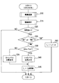
制御回路が実行するタスク付与処理を示すフローチャートであり、
画像認識処理を示すフローチャートであり、
顔部品や顔方向を認識する際の具体例を示す説明図であり、
画像解析処理を示すフローチャートである。
以下に本開示にかかる実施形態を図面と共に説明する。
[本実施形態の構成]
本開示の実施形態が適用されたドライバ監視システム1は、例えば乗用車等の車両において搭載されており、この車両を自動または半自動で走行制御するオートパイロットシステム25の作動時に、車両のドライバ(運転者)の覚醒状態を監視するシステムである。このドライバ監視システム1では、ドライバの覚醒レベルが低い状態(ドライバが眠気を感じている状態)を認識すると注意喚起を行い、ドライバの覚醒状態が不明である場合にドライバに何らかの動作を行うよう要求する機能を備えている。なお、上記のドライバー監視システム1が搭載される車両は、ホスト車両あるいは主車両とも言及される。
本開示の実施形態が適用されたドライバ監視システム1は、例えば乗用車等の車両において搭載されており、この車両を自動または半自動で走行制御するオートパイロットシステム25の作動時に、車両のドライバ(運転者)の覚醒状態を監視するシステムである。このドライバ監視システム1では、ドライバの覚醒レベルが低い状態(ドライバが眠気を感じている状態)を認識すると注意喚起を行い、ドライバの覚醒状態が不明である場合にドライバに何らかの動作を行うよう要求する機能を備えている。なお、上記のドライバー監視システム1が搭載される車両は、ホスト車両あるいは主車両とも言及される。
詳細にはドライバ監視システム1は、図1に示すように、制御回路10、カメラ21、照明機器22、オートパイロットシステム25、押ボタン26、警報機器31、シート振動機器32、空調変更機器33を備えている。
カメラ21は、車両の内部においてドライバの前方に配置されており、ドライバの顔が撮像範囲内になるよう設定されている。
照明機器22は、カメラ21のための補助光源として機能し、ドライバの顔に向けて例えば赤外光を照射する。赤外光の照射タイミングについては、常時点灯していてもよいし、カメラ21による撮像周期と同期するよう、発光タイミングが制御回路10によって制御されるよう構成されていてもよい。
オートパイロットシステム25は、車両の加減速および操舵を制御することでドライバが操作を行うことなく車両を制御(自動運転)するシステムである。オートパイロットシステム25は、自動運転を行っているか否かを示す信号を制御回路10に送る。なお、オートパイロットシステム25は、車両の加減速および操舵のうちの一方を制御する半自動運転を行うよう設定されていてもよい。
押ボタン26は、ドライバの手の届く範囲に配置された物理的なスイッチとして構成されている。押ボタン26が操作された場合、この操作は制御回路10にて認識されるよう設定されている。
警報機器31は、音や光でドライバに注意を促すための構成であり、制御回路10からの指令を受けて作動する。
シート振動機器32は、ドライバのシートに埋め込まれたバイブレータとして構成されており、制御回路10からの指令を受けて作動する。
空調変更機器33は、制御回路10からの指令を受けて、車両における空調装置の風量や風向、或いは設定温度を変更する機能を有する。
制御回路10は、ドライバ監視システムに含まれるドライバ監視装置の一部として供給されることもできる。制御回路10は、CPU11、およびROM、RAM等のメモリ12を備えた周知のコンピュータとして構成されている。CPU11は、メモリ12に記録されたプログラムに従って後述する各種処理あるいはフローチャートの処理を実施する。
ここで、この出願に記載されるフローチャート、あるいは、フローチャートの処理は、複数のセクション(あるいはステップと言及される)を含み、各セクションは、たとえば、S10と表現される。さらに、各セクションは、複数のサブセクションに分割されることができる、一方、複数のセクションが合わさって一つのセクションにすることも可能である。さらに、各セクションは、デバイス、モジュール、ミーンズとして言及されることができる。また、上記の複数のセクションの各々あるいは組合わさったものは、(i)ハードウエアユニット(例えば、コンピュータ)と組み合わさったソフトウエアのセクションのみならず、(ii)ハードウエア(例えば、集積回路、配線論理回路)のセクションとして、関連する装置の機能を含みあるいは含まずに実現できる。さらに、ハードウエアのセクションは、マイクロコンピュータの内部に含まれることもできる。
[本実施形態の処理]
このように構成されたドライバ監視システム1において、制御回路10は、図2に示すタスク付与処理を実施する。タスク付与処理では、オートパイロットシステム25の作動中に、ドライバが眠っていないことを確認するために、ドライバに何らかの動作を行うようタスク(指示)を与える。ただし、本実施形態においては、ドライバに対する負荷を軽減するために、ドライバの覚醒状態が明確である場合にはタスクを与えることはなく、ドライバの覚醒状態が不明確である場合に、ドライバの覚醒状態を確認するためにタスクを与えるよう設定している。
このように構成されたドライバ監視システム1において、制御回路10は、図2に示すタスク付与処理を実施する。タスク付与処理では、オートパイロットシステム25の作動中に、ドライバが眠っていないことを確認するために、ドライバに何らかの動作を行うようタスク(指示)を与える。ただし、本実施形態においては、ドライバに対する負荷を軽減するために、ドライバの覚醒状態が明確である場合にはタスクを与えることはなく、ドライバの覚醒状態が不明確である場合に、ドライバの覚醒状態を確認するためにタスクを与えるよう設定している。
なお、タスク付与処理は、例えばオートパイロットシステム25の電源が投入されると開始される処理である。
詳細には、図2に示すように、まず、画像認識処理を実施する(S10)。画像認識処理は、カメラ21による撮像画像からドライバの状態を認識する処理である。この画像認識処理では、図3に示すように、まず、カメラ21からの撮像画像を取得する(S110)。
続いて、撮像画像中から顔領域を抽出し(S115)、さらに顔部品を抽出する(S120)。これらの処理は、図4(a)に示すように、撮像画像を画像処理することで顔の形状らしい領域を認識し、この領域を含む矩形の領域を顔領域として認識する。そして、この顔領域内においてエッジ(隣接する画素の輝度差が基準値以上の部位)を検出し、形状を認識することで顔部品を特定する。
続いて、頭部姿勢を推定する(S125)。この処理では、顔部品の位置関係に基づいて図4(b)に示すように顔の方向を推定する。
次に、開眼度を推定する(S130)。この処理では、顔部品のうちの目の部分に着目し、例えば瞼のカーブ(眼球の上側のエッジ)の曲率半径を求める。なお、この曲率半径が大きくなるほど開眼度が低いと判定される。
続いて、開眼度の推定結果をメモリに記録させる(S135)。ただし、顔部品が抽出できなかった場合や、開眼度を推定できなかった場合には、その旨をメモリに記録させる。
このような処理が終了すると画像認識処理を終了する。画像認識処理が終了すると、図2に戻り画像解析処理を実施する(S15)。画像解析処理は、画像認識処理による認識結果を利用して画像の状態を認識するとともに、必要に応じてドライバに対して動作を要求する処理である。また、必要に応じてドライバに対して注意喚起を行う処理である。
画像認識処理では、図5に示すように、まず、ドライバ状態を推定する(S210)。ここで、ドライバ状態とは、ドライバの覚醒状態を示す。ただし、覚醒状態はドライバ状態の1つであり、覚醒状態以外に、例えば、心臓発作が発生したことと等のドライバの健康状態や、携帯電話やカーナビゲーション装置等をドライバが操作することによるドライバの脇見運転状態等を示してもよい。
本実施形態において、ドライバの覚醒状態を推定するには、まず、例えば過去5秒間の平均開眼度や瞬き回数等を、メモリ12に記録された開眼度から求め、平均開眼度や瞬き回数が予め設定された閾値未満であれば、覚醒レベルが低く(ドライバが眠気を感じている状態)、平均開眼度や瞬き回数が閾値以上であれば覚醒レベルが高い(ドライバが眠気を感じていない状態)と判断する。
続いて、ドライバ状態の認識率と予め設定された判定認識率とを比較する(S215)。判定認識率はドライバ状態が信頼できるものか否かを判断するための基準であり、例えば70~90%程度の値に設定される。
ドライバ状態の認識率は、開眼度の認識結果がメモリ12に記録された割合を表す。より具体的には、ドライバ状態の認識率は、例えば過去5秒間に得られる撮像画像の数(フレーム数)に対する平均開眼度が正常に認識できたフレーム数の割合を表す。
なお、本実施形態では、ドライバ状態が認識できた場合はメモリ12に記録するよう構成しているが、例えば、認識状態フラグ(認識の確からしさの尤度)を出力するようにしてもよい。
ドライバ状態の認識率が判定閾値以上であれば(S215:YES)、ドライバ状態の推定結果をメモリ12に記録する(S220)。ここでの推定結果は、覚醒レベルが高い場合にドライバ状態がOKである旨が記録され、覚醒レベルが低い場合にドライバ状態がNG(NO GOOD)である旨が記録される。S220の処理が終了すると、画像解析処理を終了する。
ドライバ状態の認識率が判定閾値未満であれば(S215:NO)、最新の撮像画像において顔部品が認識できているか否かを判定する(S230)。顔部品が認識できていれば(S230:YES)、運転継続時間tと画像タスク要求間隔t1とを比較する(S235)。
ここで、運転継続時間tは、ドライバ状態が最後に認識されてから、或いは、ドライバへの要求に対する動作が最後に認識されてからの時間を表す。つまり、運転継続時間tは、ドライバ状態が認識されるか(S220の処理が実施されるか)、ドライバへの要求に対する動作を認識したとき(S340の処理が実施されたとき)にリセットされる。
また、画像タスク要求時間t1は、画像処理にて認識可能なドライバ動作を要求する周期を示し、予め設定された値とされている。なお、この値は、後述する処理にて変更可能とされている。
運転継続時間tが画像タスク要求時間t1以下であれば(S235:NO)、メモリ12に記録されたドライバ状態の判定結果や後述する要求に対する動作の判定結果をクリアし(S250)、画像解析処理を終了する。
また、運転継続時間tが画像タスク要求時間t1を超えていれば(S235:YES)、画像処理タスクを要求する(S260)。ここで、画像処理タスクとは、ドライバに口を開けさせたり、顔の向きを変更させたり、ウインクさせたりというように、画像処理によってドライバの動作を検出するための要求を示す。より詳細には、撮像画像においてカメラ21に対する顔部品の位置関係を変更させるよう要求することを示す。
続いて、前述の画像認識処理を再度実施し(S265)、その後、要求に対する動作を認識する(S270)。すなわち、要求の前後における顔部品の位置関係の変化を認識することで、ドライバが要求に応答したことを認識する。
そして、要求に対する動作を認識できたか否かを判定する(S275)。要求に対する動作を認識できていれば(S275:YES)、要求に対する動作が認識できた旨(OK)をメモリ12に記録させる(S340)。
また、要求に対する動作が認識できていなければ(S275:NO)、要求を行ってから、ドライバが動作を行うまでのタイムラグ(遅れ時間)に余裕時間を付加した待機時間が経過したか否かを判定する(S280)。待機時間が経過していなければ(S280:NO)、S265の処理に戻る。
待機時間が経過していれば(S280:YES)、要求に対する動作が認識できなかった旨(NG)をメモリ12に記録させる(S345)。このような処理が終了すると、画像解析処理を終了する。
ところで、S230の処理にて、顔部品が認識できていなければ(S230:NO)、運転継続時間tと非画像タスク要求間隔t2とを比較する(S235)。ここで、非画像タスク要求間隔t2は、画像処理によらずに認識可能なドライバの動作を要求する周期を示し、画像タスク要求時間t1以下の値に設定されている。
運転継続時間tが非画像タスク要求時間t2以下であれば(S240:NO)、前述のS25の処理に移行する。また、運転継続時間tが非画像タスク要求時間t2以下であれば(S240:YES)、非画像処理タスクを要求する(S310)。
非画像処理タスクは、画像処理によらずにドライバの動作を検出するための動作を要求するものであり、本実施形態では押ボタン26を押すよう要求する。続いて、要求に対する動作を認識する(S315)。この処理では、押ボタン26からの信号を検出する。
続いて、要求に対する動作を認識できたか否かを判定する(S320)。要求に対する動作を認識できていれば(S320:YES)、前述のS340の処理に移行する。また、要求に対する動作を認識できていなければ(S320:NO)、要求を行ってから待機時間が経過したか否かを判定する(S325)。待機時間が経過していなければ(S325:NO)、S315の処理に戻る。
また、待機時間が経過していれば(S325:YES)、前述のS345の処理に移行する。
このような画像解析処理が終了すると、図2に戻りメモリ12においてOKまたはNGの判定結果が記録されているか否かを判定する(S20)。この処理では前述のS250の処理にて判定結果がクリアされている場合には否定判定され、その他の場合には肯定判定される。
判定結果が記録されていなければ(S20:NO)、S10の処理に戻る。また、判定結果が記録されていれば(S20:YES)、判定結果の種別(OKまたはNG)を判定する(S25)。
判定結果がOKであれば(S25:OK)、画像タスク要求時間t1をα(αは例えば1分程度の値)だけ増加させ(S60)、S10の処理に戻る。また、判定結果がNGであれば(S25:NG)、NGレベルを判定する(S30)。
ここで、NGレベルは、NG判定された頻度やNG判定された際の処理の種別(開眼度によってNG判定されたか、要求に対する動作が得られなかったか等)によって所定の値が付与され、この値が基準となる閾値を超えるとNGレベルが高いと判定される。
NGレベルが低ければ(S30:NO)、ローレベル注意を出力する(S35)。ローレベル注意は、例えば、警報機器31による警告を示す。
また、NGレベルが高ければ(S30:YES)、ハイレベル注意を出力する(S40)。ハイレベル注意は、警報機器31による警告に加えて、シート振動機器32によってシートに振動を与える処理、および空調変更機器33によって運転者の顔に冷風を当てる処理等を行うことを示す。すなわち、ハイレベル注意では、ローレベル注意よりも強い警告を与えることで、ドライバに強く注意を促す。
S35またはS40の処理にて注意喚起を行う処理を終了すると、画像タスク要求時間t1を初期値に戻し(S45)、S10の処理に戻る。
[本実施形態による効果]
以上のように詳述したドライバ監視システム1において、制御回路10はドライバの状態を認識し、認識安定性を判定する。また、認識安定性が予め設定された基準値未満である場合に、認識安定性が基準値以上である場合とは異なる動作を行うようドライバに要求するか、あるいは同一の動作であっても異なるタイミングでドライバに要求する。そして、要求に対応するドライバの動作を検出する。
以上のように詳述したドライバ監視システム1において、制御回路10はドライバの状態を認識し、認識安定性を判定する。また、認識安定性が予め設定された基準値未満である場合に、認識安定性が基準値以上である場合とは異なる動作を行うようドライバに要求するか、あるいは同一の動作であっても異なるタイミングでドライバに要求する。そして、要求に対応するドライバの動作を検出する。
このような構成によれば、認識安定性が基準値未満である場合にドライバに対して何らかの動作を要求するので、覚醒状態等のドライバ状態が正しく認識できない場合であっても、ドライバの覚醒状態を維持することができる。
また、画像処理で顔部品を常時安定的に認識することは容易ではなく、外乱光(太陽光による顔面への直射やアンバランスな照射)やメガネへの風景の映り込みなどで、認識が連続的または断続的に誤検知や未検知に陥ることが考えられる。しかしながら本実施形態では、そのような場合では、ドライバに煩わしくても非画像処理タスクを実行することで安全性を確保することができる。
また、上記のドライバ監視システム1において制御回路10は、ドライバの顔を撮像した撮像画像を取得し、撮像画像からドライバの顔の構成要素を認識する。そして、制御回路10は、認識安定性が予め設定された基準値未満であって、ドライバの顔の構成要素のうちの予め設定された設定部位を認識できない場合、画像処理によらずにドライバの動作を検出するための非画像動作を要求する。
このようなドライバ監視システム1によれば、画像処理を用いないでドライバの動作を検出するための動作(非画像動作)を要求するのでドライバの動作を良好に検出することができる。
さらに、上記のドライバ監視システム1において制御回路10は、ドライバの顔の構成要素のうちの設定部位(顔部品)を認識できた場合に、基準周期(t1)毎にドライバに動作を要求し、設定部位を認識できなかった場合に、基準周期よりも短い短縮周期(t2)毎にドライバに動作を要求する。
ここで、設定部位とは、顔向き方向を推定するために最低限必要な顔部品、例えば、顔幅と鼻との組み合わせや、両目と鼻との組み合わせ等を意味する。また、眠気推定の場合の設定部位は、左右の目の少なくとも片方の開眼度とすることができる。
このようなドライバ監視システム1によれば、設定部位を認識できなかった場合にはドライバに動作を要求する周期を短くするので、ドライバの覚醒状態を維持しやすくすることができる。
また、上記のドライバ監視システム1において制御回路10は、設定部位を認識できた場合に、設定部位に変化を与える動作を要求し、設定部位を認識できなかった場合に、ドライバ操作を検知するディテクタ(押ボタン26)にて検知可能な動作を要求する。
このようなドライバ監視システム1によれば、設定部位を認識できる場合には画像で認識できる動作を要求することでドライバの負担を軽くし、一方で設定部位を認識できない場合にはディテクタにて検知可能な動作を要求するので、確実にドライバによる動作を検出することができる。
さらに、上記のドライバ監視システム1において制御回路10は、要求に対するドライバの動作が検出できなかった場合、および認識したドライバの状態が運転に支障を及ぼす可能性がある状態である場合に、ドライバに対して注意喚起を行う。
このようなドライバ監視システム1によれば、ドライバが運転に支障を及ぼさないように注意を促すことができる。また、要求に対するドライバの動作が検出されたときや、ドライバの状態が運転に支障を及ぼさない場合に注意喚起を行わないようにすることで、ドライバに対する不要な警告が実施されにくくすることができる。
また、上記のドライバ監視システム1において制御回路10は、注意喚起を行ってから予め設定された注意喚起間隔時間以内には、注意喚起を禁止する。ただし本実施形態では、ドライバの状態が「運転に支障を及ぼす可能性がある状態」である場合が認識された場合には、注意喚起を行う。
このようなドライバ監視システム1によれば、頻繁に注意喚起が実施されることによる煩わしさを軽減することができる。
さらに、上記のドライバ監視システム1において制御回路10は、ドライバの動作が検出できた場合に、注意喚起間隔時間をより長い時間に変更し、注意喚起を行った場合に、注意喚起間隔時間をより短い時間に変更する。
このようなドライバ監視システム1によれば、注意喚起間隔時間を変更することで、ドライバに煩わしくないようにすること、および覚醒状態を維持することを両立することができる。
なお、状態認識の処理によってドライバの状態が認識できた場合にも注意喚起間隔時間をより長い時間に変更するようにしてもよい。
[その他の実施形態]
本開示は、上記の実施形態によって何ら限定して解釈されない。次のような構成としても提供される。なお、下記の記載において、上記の実施形態とは異なる構成以外は、上記実施形態と同様であり、よって、上記の実施形態で説明に使用された図も同様に参照されることができる。
本開示は、上記の実施形態によって何ら限定して解釈されない。次のような構成としても提供される。なお、下記の記載において、上記の実施形態とは異なる構成以外は、上記実施形態と同様であり、よって、上記の実施形態で説明に使用された図も同様に参照されることができる。
例えば、上記実施形態において、画像処理を用いることなくドライバの操作を検出するための構成として、押ボタン26を押すよう要求し、押ボタン26への操作を検出する構成を採用したが、押ボタン26に限らず、例えば、ペダルやステアリングの操作を要求し、この操作をペダルやステアリングに設けられたセンサによって検出してもよい。
また、上記実施形態では、ドライバ状態が明確である場合にはドライバに動作を求めないよう構成したが、ドライバ状態が明確である場合にも、ある時間毎に何らかの動作を求めるようにしてもよい。この場合、ドライバ状態が不明確である場合よりも動作を要求する周期を長くする構成や、ドライバの負担にならないより軽い動作を要求する構成を採用してもよい。
つまり、ドライバ状態が明確である場合にも動作を要求する場合、ドライバ状態が不明確である場合とは異なる動作を求めればよい。
なお、次の点が注記される。上記実施形態における押ボタン26は、ディテクターあるいは検知デバイス/ミーンズとも言及される。また、上記実施形態において制御回路10が実施する処理のうちの、S30、S35、S40の処理は、注意喚起部/デバイス/ミーンズとも言及され、S45、S60の処理は、間隔時間変更部/デバイス/ミーンズとも言及される。
さらに、上記実施形態において、制御回路10が実施する処理のうちの、S110の処理は、撮像画像取得部/デバイス/ミーンズとも言及され、S120の処理は、顔認識部/デバイス/ミーンズとも言及される。また、S210の処理は、状態認識部/デバイス/ミーンズとも言及され、S215の処理は、認識安定性判定部/デバイス/ミーンズとも言及される。
さらに、上記実施形態において、制御回路10が実施する処理のうちの、S230、S235、S240、S260、S310の処理は、動作要求部/デバイス/ミーンズとも言及され、S235、S240、S250の処理は、注意禁止部/デバイス/ミーンズとも言及される。また、S270、S315の処理は、動作検出部/デバイス/ミーンズとも言及される。
本開示は、実施例に準拠して記述されたが、本開示は当該実施例や構造に限定されるものではないと理解される。本開示は、様々な変形例や均等範囲内の変形をも包含する。加えて、様々な組み合わせや形態、さらには、それらに一要素のみ、それ以上、あるいはそれ以下、を含む他の組み合わせや形態をも、本開示の範疇や思想範囲に入るものである。
Claims (7)
- 車両のドライバを監視するドライバ監視装置であって、
ドライバ監視を制御する制御回路(10)を有し、
前記制御回路は、
ドライバの状態を認識する状態認識部(S210)と、
前記状態認識部による認識安定性を判定する認識安定性判定部(S215)と、
前記認識安定性が予め設定された基準値未満である場合に、前記認識安定性が前記基準値以上である場合とは異なる動作を行うよう前記ドライバに要求するか、あるいは同一の動作であっても異なるタイミングで前記ドライバに要求する動作要求部(S230、S235、S240、S260、S310)と、
前記要求に対応するドライバの動作を検出する動作検出部(S270、S315)と、を含む
ドライバ監視装置。 - 請求項1に記載のドライバ監視装置において、前記制御回路は、
ドライバの顔を撮像した撮像画像を取得する撮像画像取得部(S110)と、
前記撮像画像からドライバの顔の構成要素を認識する顔認識部(S120)と、
を含み、
前記動作要求部は、前記認識安定性が予め設定された基準値未満であって、ドライバの顔の構成要素のうちの予め設定された設定部位を認識できない場合、画像処理によらずにドライバの動作を検出するための動作である非画像動作を要求する
ドライバ監視装置。 - 請求項2に記載のドライバ監視装置において、
前記動作要求部は、前記設定部位を認識できた場合に、基準周期毎に前記ドライバに動作を要求し、前記設定部位を認識できなかった場合に、前記基準周期よりも短い短縮周期毎に前記ドライバに動作を要求する
ドライバ監視装置。 - 請求項2または請求項3に記載のドライバ監視装置において、
前記動作要求部は、前記設定部位を認識できた場合に、前記設定部位に変化を与える動作を要求し、前記設定部位を認識できなかった場合に、ドライバ操作を検知するディテクタ(26)にて検知可能な動作を要求する
ドライバ監視装置。 - 請求項1~請求項4の何れか1項に記載のドライバ監視装置において、前記制御回路は、
前記動作検出部にて前記要求に対するドライバの動作が検出できなかった場合、および前記状態認識部にて認識したドライバの状態が運転に支障を及ぼす可能性がある状態である場合に、前記ドライバに対して注意喚起を行う注意喚起部(S30、S35、S40)、を含む
ドライバ監視装置。 - 請求項5に記載のドライバ監視装置において、前記制御回路は、
前記注意喚起を行ってから予め設定された注意喚起間隔時間以内には、前記注意喚起部による注意喚起を禁止する注意禁止部(S235、S240、S250)、
を含む
ドライバ監視装置。 - 請求項6に記載のドライバ監視装置において、前記制御回路は、
前記動作検出部によって前記ドライバの動作が検出できた場合に、前記注意喚起間隔時間をより長い時間に変更し、前記注意喚起部によって注意喚起を行った場合に、前記注意喚起間隔時間をより短い時間に変更する間隔時間変更部(S45、S60)、
を含む
ドライバ監視装置。
Priority Applications (1)
| Application Number | Priority Date | Filing Date | Title |
|---|---|---|---|
| US15/034,144 US9888875B2 (en) | 2013-11-13 | 2014-10-09 | Driver monitoring apparatus |
Applications Claiming Priority (2)
| Application Number | Priority Date | Filing Date | Title |
|---|---|---|---|
| JP2013235105A JP6314435B2 (ja) | 2013-11-13 | 2013-11-13 | ドライバ監視装置 |
| JP2013-235105 | 2013-11-13 |
Publications (1)
| Publication Number | Publication Date |
|---|---|
| WO2015072069A1 true WO2015072069A1 (ja) | 2015-05-21 |
Family
ID=53057025
Family Applications (1)
| Application Number | Title | Priority Date | Filing Date |
|---|---|---|---|
| PCT/JP2014/005135 Ceased WO2015072069A1 (ja) | 2013-11-13 | 2014-10-09 | ドライバ監視装置 |
Country Status (3)
| Country | Link |
|---|---|
| US (1) | US9888875B2 (ja) |
| JP (1) | JP6314435B2 (ja) |
| WO (1) | WO2015072069A1 (ja) |
Cited By (1)
| Publication number | Priority date | Publication date | Assignee | Title |
|---|---|---|---|---|
| US9888875B2 (en) | 2013-11-13 | 2018-02-13 | Denso Corporation | Driver monitoring apparatus |
Families Citing this family (15)
| Publication number | Priority date | Publication date | Assignee | Title |
|---|---|---|---|---|
| JP6510454B2 (ja) * | 2016-03-30 | 2019-05-08 | 本田技研工業株式会社 | 車両用覚醒検知装置 |
| US20210291817A1 (en) | 2016-06-23 | 2021-09-23 | State Farm Mutual Automobile Insurance Company | Systems and methods for environmental analysis based upon vehicle sensor data |
| JP6801274B2 (ja) | 2016-07-11 | 2020-12-16 | 株式会社デンソー | 運転支援装置、及び運転支援方法 |
| JP6665748B2 (ja) * | 2016-09-29 | 2020-03-13 | トヨタ自動車株式会社 | 車両用覚醒システム |
| JP6888542B2 (ja) * | 2017-12-22 | 2021-06-16 | トヨタ自動車株式会社 | 眠気推定装置及び眠気推定方法 |
| JP6418342B1 (ja) * | 2018-02-07 | 2018-11-07 | オムロン株式会社 | データ処理装置、モニタリングシステム、覚醒システム、データ処理方法、及びデータ処理プログラム |
| JP6418341B1 (ja) * | 2018-02-07 | 2018-11-07 | オムロン株式会社 | データ処理装置、モニタリングシステム、覚醒システム、データ処理方法、及びデータ処理プログラム |
| US10776644B1 (en) * | 2018-03-07 | 2020-09-15 | State Farm Mutual Automobile Insurance Company | Image analysis technologies for assessing safety of vehicle operation |
| US10275670B1 (en) | 2018-03-07 | 2019-04-30 | State Farm Mutual Automobile Insurance Company | Image analysis technologies for identifying abnormal vehicle conditions |
| US11254270B1 (en) | 2018-05-02 | 2022-02-22 | State Farm Mutual Automobile Insurance Company | Technologies for using image analysis to facilitate adjustments of vehicle components |
| US11430264B2 (en) * | 2018-07-16 | 2022-08-30 | Honor Device Co., Ltd. | Eye open or closed state detection method and electronic device |
| DE102018214935B4 (de) * | 2018-09-03 | 2023-11-02 | Bayerische Motoren Werke Aktiengesellschaft | Verfahren, Vorrichtung, Computerprogramm und Computerprogrammprodukt zum Ermitteln einer Aufmerksamkeit eines Fahrers eines Fahrzeuges |
| JP7328089B2 (ja) * | 2019-09-05 | 2023-08-16 | トヨタ自動車株式会社 | 閉眼判定装置 |
| JP7127661B2 (ja) * | 2020-03-24 | 2022-08-30 | トヨタ自動車株式会社 | 開眼度算出装置 |
| JP7264121B2 (ja) | 2020-07-01 | 2023-04-25 | トヨタ自動車株式会社 | 車両の表示・音声出力制御システム |
Citations (6)
| Publication number | Priority date | Publication date | Assignee | Title |
|---|---|---|---|---|
| JP2007219578A (ja) * | 2006-02-14 | 2007-08-30 | Omron Corp | 異常検出装置および方法、記録媒体、並びに、プログラム |
| JP2007264883A (ja) * | 2006-03-28 | 2007-10-11 | Mitsubishi Fuso Truck & Bus Corp | 車両用覚醒度情報出力装置 |
| JP2008137639A (ja) * | 2006-11-06 | 2008-06-19 | Quality Kk | 車両制御装置および車両制御プログラム |
| JP2009031905A (ja) * | 2007-07-25 | 2009-02-12 | Nissan Motor Co Ltd | 居眠り運転防止装置 |
| JP2009048605A (ja) * | 2007-07-24 | 2009-03-05 | Nissan Motor Co Ltd | 居眠り運転防止装置 |
| JP2012011810A (ja) * | 2010-06-29 | 2012-01-19 | Honda Motor Co Ltd | 車両用顔画像撮像装置 |
Family Cites Families (17)
| Publication number | Priority date | Publication date | Assignee | Title |
|---|---|---|---|---|
| JP3158663B2 (ja) * | 1992-06-25 | 2001-04-23 | いすゞ自動車株式会社 | 居眠り運転防止装置 |
| US5570698A (en) * | 1995-06-02 | 1996-11-05 | Siemens Corporate Research, Inc. | System for monitoring eyes for detecting sleep behavior |
| US6542081B2 (en) * | 1996-08-19 | 2003-04-01 | William C. Torch | System and method for monitoring eye movement |
| US5867587A (en) * | 1997-05-19 | 1999-02-02 | Northrop Grumman Corporation | Impaired operator detection and warning system employing eyeblink analysis |
| JPH11185200A (ja) | 1997-12-22 | 1999-07-09 | Mitsubishi Motors Corp | 自動走行制御可能な車両におけるドライバの意識レベル判定方法 |
| US6724920B1 (en) * | 2000-07-21 | 2004-04-20 | Trw Inc. | Application of human facial features recognition to automobile safety |
| US6950027B2 (en) * | 2000-08-23 | 2005-09-27 | Siemens Vdo Automotive Corporation | Method to alert drowsy driver |
| US7027621B1 (en) * | 2001-03-15 | 2006-04-11 | Mikos, Ltd. | Method and apparatus for operator condition monitoring and assessment |
| JP3632088B2 (ja) | 2002-03-29 | 2005-03-23 | 国土交通省国土技術政策総合研究所長 | 車両検出方法 |
| DE10322458A1 (de) | 2003-05-16 | 2004-12-02 | Daimlerchrysler Ag | Verfahren und Vorrichtung zur Beeinflussung der Beanspruchung eines Fahrers in einem Kraftfahrzeug |
| JP5056067B2 (ja) | 2007-02-26 | 2012-10-24 | 株式会社デンソー | 居眠り警報装置 |
| US7652583B2 (en) * | 2007-03-20 | 2010-01-26 | Deere & Company | Method and system for maintaining operator alertness |
| US7719431B2 (en) * | 2007-10-05 | 2010-05-18 | Gm Global Technology Operations, Inc. | Systems, methods and computer products for drowsy driver detection and response |
| JP2010020618A (ja) | 2008-07-11 | 2010-01-28 | Toyota Motor Corp | 運転者覚醒装置 |
| JP5298923B2 (ja) | 2009-02-17 | 2013-09-25 | 日産自動車株式会社 | 居眠り防止装置及び居眠り防止方法 |
| JP5774409B2 (ja) | 2011-08-19 | 2015-09-09 | ダイムラー・アクチェンゲゼルシャフトDaimler AG | 運転支援制御装置 |
| JP6314435B2 (ja) | 2013-11-13 | 2018-04-25 | 株式会社デンソー | ドライバ監視装置 |
-
2013
- 2013-11-13 JP JP2013235105A patent/JP6314435B2/ja not_active Expired - Fee Related
-
2014
- 2014-10-09 US US15/034,144 patent/US9888875B2/en active Active
- 2014-10-09 WO PCT/JP2014/005135 patent/WO2015072069A1/ja not_active Ceased
Patent Citations (6)
| Publication number | Priority date | Publication date | Assignee | Title |
|---|---|---|---|---|
| JP2007219578A (ja) * | 2006-02-14 | 2007-08-30 | Omron Corp | 異常検出装置および方法、記録媒体、並びに、プログラム |
| JP2007264883A (ja) * | 2006-03-28 | 2007-10-11 | Mitsubishi Fuso Truck & Bus Corp | 車両用覚醒度情報出力装置 |
| JP2008137639A (ja) * | 2006-11-06 | 2008-06-19 | Quality Kk | 車両制御装置および車両制御プログラム |
| JP2009048605A (ja) * | 2007-07-24 | 2009-03-05 | Nissan Motor Co Ltd | 居眠り運転防止装置 |
| JP2009031905A (ja) * | 2007-07-25 | 2009-02-12 | Nissan Motor Co Ltd | 居眠り運転防止装置 |
| JP2012011810A (ja) * | 2010-06-29 | 2012-01-19 | Honda Motor Co Ltd | 車両用顔画像撮像装置 |
Cited By (1)
| Publication number | Priority date | Publication date | Assignee | Title |
|---|---|---|---|---|
| US9888875B2 (en) | 2013-11-13 | 2018-02-13 | Denso Corporation | Driver monitoring apparatus |
Also Published As
| Publication number | Publication date |
|---|---|
| JP6314435B2 (ja) | 2018-04-25 |
| US20160262682A1 (en) | 2016-09-15 |
| JP2015095162A (ja) | 2015-05-18 |
| US9888875B2 (en) | 2018-02-13 |
Similar Documents
| Publication | Publication Date | Title |
|---|---|---|
| JP6314435B2 (ja) | ドライバ監視装置 | |
| JP6341055B2 (ja) | 車載制御装置 | |
| JP5125745B2 (ja) | 運転支援装置、運転支援方法 | |
| JP5326521B2 (ja) | 覚醒状態判断装置及び覚醒状態判断方法 | |
| US9526448B2 (en) | State estimation device and state estimation program | |
| WO2019073708A1 (ja) | 車両用運転支援装置 | |
| US20140121927A1 (en) | Vehicle emergency evacuation device | |
| JP5666383B2 (ja) | 眠気推定装置及び眠気推定方法 | |
| CN115335269B (zh) | 信息提示控制装置以及功能控制装置 | |
| JP6090129B2 (ja) | 視認領域推定装置 | |
| JP6926636B2 (ja) | 状態推定装置 | |
| JP6579014B2 (ja) | 自動ブレーキ制御装置及びコンピュータプログラム | |
| WO2015122158A1 (ja) | 運転支援装置 | |
| JP2014144096A (ja) | 覚醒度検出装置、および覚醒度検出方法 | |
| JP2009244959A (ja) | 運転支援装置、運転支援方法 | |
| CN111409551B (zh) | 注意提醒装置及注意提醒系统 | |
| JP6730096B2 (ja) | 乗員状態監視装置 | |
| JP6256433B2 (ja) | 運転者状態検出装置 | |
| JP2008305190A (ja) | 居眠り警告装置及び自動車 | |
| US11048951B2 (en) | Occupant state recognition apparatus | |
| JP2018133007A (ja) | 警報装置 | |
| JP5447335B2 (ja) | 報知システム | |
| JP7046748B2 (ja) | 運転者状態判定装置および運転者状態判定方法 | |
| JP6958982B2 (ja) | 覚醒機能を備えた電子装置、覚醒プログラムおよび覚醒方法 | |
| JP2018143285A (ja) | 生体状態判定装置、生体状態判定システム、及び、生体状態判定方法 |
Legal Events
| Date | Code | Title | Description |
|---|---|---|---|
| 121 | Ep: the epo has been informed by wipo that ep was designated in this application |
Ref document number: 14861583 Country of ref document: EP Kind code of ref document: A1 |
|
| WWE | Wipo information: entry into national phase |
Ref document number: 15034144 Country of ref document: US |
|
| NENP | Non-entry into the national phase |
Ref country code: DE |
|
| 122 | Ep: pct application non-entry in european phase |
Ref document number: 14861583 Country of ref document: EP Kind code of ref document: A1 |