WO2015068489A1 - バルブ - Google Patents
バルブ Download PDFInfo
- Publication number
- WO2015068489A1 WO2015068489A1 PCT/JP2014/075583 JP2014075583W WO2015068489A1 WO 2015068489 A1 WO2015068489 A1 WO 2015068489A1 JP 2014075583 W JP2014075583 W JP 2014075583W WO 2015068489 A1 WO2015068489 A1 WO 2015068489A1
- Authority
- WO
- WIPO (PCT)
- Prior art keywords
- valve
- chamber
- piston
- seat
- chamber side
- Prior art date
- Legal status (The legal status is an assumption and is not a legal conclusion. Google has not performed a legal analysis and makes no representation as to the accuracy of the status listed.)
- Ceased
Links
Images







Classifications
-
- F—MECHANICAL ENGINEERING; LIGHTING; HEATING; WEAPONS; BLASTING
- F16—ENGINEERING ELEMENTS AND UNITS; GENERAL MEASURES FOR PRODUCING AND MAINTAINING EFFECTIVE FUNCTIONING OF MACHINES OR INSTALLATIONS; THERMAL INSULATION IN GENERAL
- F16F—SPRINGS; SHOCK-ABSORBERS; MEANS FOR DAMPING VIBRATION
- F16F9/00—Springs, vibration-dampers, shock-absorbers, or similarly-constructed movement-dampers using a fluid or the equivalent as damping medium
- F16F9/32—Details
- F16F9/34—Special valve constructions; Shape or construction of throttling passages
- F16F9/348—Throttling passages in the form of annular discs or other plate-like elements which may or may not have a spring action, operating in opposite directions or singly, e.g. annular discs positioned on top of the valve or piston body
- F16F9/3484—Throttling passages in the form of annular discs or other plate-like elements which may or may not have a spring action, operating in opposite directions or singly, e.g. annular discs positioned on top of the valve or piston body characterised by features of the annular discs per se, singularly or in combination
-
- F—MECHANICAL ENGINEERING; LIGHTING; HEATING; WEAPONS; BLASTING
- F16—ENGINEERING ELEMENTS AND UNITS; GENERAL MEASURES FOR PRODUCING AND MAINTAINING EFFECTIVE FUNCTIONING OF MACHINES OR INSTALLATIONS; THERMAL INSULATION IN GENERAL
- F16F—SPRINGS; SHOCK-ABSORBERS; MEANS FOR DAMPING VIBRATION
- F16F9/00—Springs, vibration-dampers, shock-absorbers, or similarly-constructed movement-dampers using a fluid or the equivalent as damping medium
- F16F9/32—Details
- F16F9/34—Special valve constructions; Shape or construction of throttling passages
- F16F9/348—Throttling passages in the form of annular discs or other plate-like elements which may or may not have a spring action, operating in opposite directions or singly, e.g. annular discs positioned on top of the valve or piston body
- F16F9/3481—Throttling passages in the form of annular discs or other plate-like elements which may or may not have a spring action, operating in opposite directions or singly, e.g. annular discs positioned on top of the valve or piston body characterised by shape or construction of throttling passages in piston
-
- F—MECHANICAL ENGINEERING; LIGHTING; HEATING; WEAPONS; BLASTING
- F16—ENGINEERING ELEMENTS AND UNITS; GENERAL MEASURES FOR PRODUCING AND MAINTAINING EFFECTIVE FUNCTIONING OF MACHINES OR INSTALLATIONS; THERMAL INSULATION IN GENERAL
- F16K—VALVES; TAPS; COCKS; ACTUATING-FLOATS; DEVICES FOR VENTING OR AERATING
- F16K15/00—Check valves
- F16K15/14—Check valves with flexible valve members
- F16K15/16—Check valves with flexible valve members with tongue-shaped laminae
-
- F—MECHANICAL ENGINEERING; LIGHTING; HEATING; WEAPONS; BLASTING
- F16—ENGINEERING ELEMENTS AND UNITS; GENERAL MEASURES FOR PRODUCING AND MAINTAINING EFFECTIVE FUNCTIONING OF MACHINES OR INSTALLATIONS; THERMAL INSULATION IN GENERAL
- F16K—VALVES; TAPS; COCKS; ACTUATING-FLOATS; DEVICES FOR VENTING OR AERATING
- F16K31/00—Actuating devices; Operating means; Releasing devices
- F16K31/12—Actuating devices; Operating means; Releasing devices actuated by fluid
- F16K31/122—Actuating devices; Operating means; Releasing devices actuated by fluid the fluid acting on a piston
- F16K31/1226—Actuating devices; Operating means; Releasing devices actuated by fluid the fluid acting on a piston the fluid circulating through the piston
-
- F—MECHANICAL ENGINEERING; LIGHTING; HEATING; WEAPONS; BLASTING
- F16—ENGINEERING ELEMENTS AND UNITS; GENERAL MEASURES FOR PRODUCING AND MAINTAINING EFFECTIVE FUNCTIONING OF MACHINES OR INSTALLATIONS; THERMAL INSULATION IN GENERAL
- F16K—VALVES; TAPS; COCKS; ACTUATING-FLOATS; DEVICES FOR VENTING OR AERATING
- F16K47/00—Means in valves for absorbing fluid energy
- F16K47/04—Means in valves for absorbing fluid energy for decreasing pressure or noise level, the throttle being incorporated in the closure member
-
- Y—GENERAL TAGGING OF NEW TECHNOLOGICAL DEVELOPMENTS; GENERAL TAGGING OF CROSS-SECTIONAL TECHNOLOGIES SPANNING OVER SEVERAL SECTIONS OF THE IPC; TECHNICAL SUBJECTS COVERED BY FORMER USPC CROSS-REFERENCE ART COLLECTIONS [XRACs] AND DIGESTS
- Y10—TECHNICAL SUBJECTS COVERED BY FORMER USPC
- Y10T—TECHNICAL SUBJECTS COVERED BY FORMER US CLASSIFICATION
- Y10T137/00—Fluid handling
- Y10T137/7722—Line condition change responsive valves
- Y10T137/7771—Bi-directional flow valves
- Y10T137/7779—Axes of ports parallel
Definitions
- the present invention relates to a valve.
- the valve controls the flow direction and flow rate of fluid such as liquid and gas.
- the valve disclosed in JP2001-082526A is embodied as a piston valve of a shock absorber, and is held by a rod that enters and exits a cylindrical cylinder and is inserted into the cylinder so as to be movable in the axial direction.
- the piston valve includes a piston that is a valve disk that is formed in a cylinder and divides an expansion side chamber and a pressure side chamber filled with hydraulic oil, and an annular plate-like leaf valve that is stacked on both sides in the axial direction of the piston. It has. Furthermore, the piston is formed on both sides in the axial direction to form an annular boss portion that supports the leaf valve, a seat that is formed on the outer peripheral side of each boss portion, on which the leaf valve is seated, and an opening that is surrounded by each seat. And an extension side passage that communicates the extension side chamber and the opening on the compression side chamber side, and a pressure side passage that communicates the opening on the compression side chamber and the extension side chamber.
- the expansion side chamber When the expansion side chamber is pressurized during the extension of the shock absorber and the pressure in the expansion side chamber reaches the valve opening pressure of the leaf valve on the compression side chamber, the outer periphery of the leaf valve moves away from the seat on the compression side chamber side. Since the passage of the passage is allowed, the shock absorber generates an extension side damping force due to resistance when the hydraulic oil moves from the extension side chamber to the compression side chamber through the extension side passage.
- the compression side chamber is pressurized and the pressure side chamber pressure reaches the valve opening pressure of the leaf valve on the expansion side chamber during compression of the shock absorber, the outer periphery of the leaf valve is separated from the seat on the expansion side and the pressure side Since the passage of the passage is allowed, the shock absorber generates a compression side damping force due to the resistance when the hydraulic oil passes through the compression side passage and moves from the compression side chamber to the extension side chamber.
- the piston disclosed in JP2001-082526A is a molded piston integrated with a synthetic resin piston ring attached to the outer periphery thereof, and smoothly slides inside the cylinder by slidingly contacting the inner peripheral surface of the cylinder via the piston ring. Can be moved to.
- a piston ring is formed by vertically stacking pistons mounted on the outer periphery of an annular plate-shaped base material that will later become a piston ring, and sequentially pushing the piston into a heated mold. At the same time, the piston ring and the piston are integrated. At this time, a large force is applied to the piston and pushed into the mold.
- the boss portions of the overlapping pistons may not contact each other.
- the contact area of the piston may be extremely small.
- the problems associated with the deformation of the seat described above are handled by stacking the valve discs vertically, regardless of whether the valve disc is used for a shock absorber, the seat shape, the presence or absence of the piston ring, and the mounting method. In this case, this may occur when the boss portions cannot be brought into contact with each other, and the outer diameters of the seats on both sides (the distance from the valve disk to the outer peripheral edge of each seat) are different.
- the object of the present invention is to provide a valve capable of suppressing the deformation of the seat even when the bosses are not in contact with each other and the outer diameters of the seats on both sides are different when handling the valve discs vertically. It is to be.
- a valve disk that divides one chamber and the other chamber, and an annular plate-shaped leaf valve that is stacked on the one chamber side and the other chamber side of the valve disk, respectively.
- the valve disc is formed on the one chamber side and the other chamber side, respectively, and is formed on the outer peripheral side of the boss portion on each of the one chamber side and the other chamber side to support the leaf valve.
- the other passage that communicates with the opening, and at least one of the sheets on the one chamber side and the other chamber side is disposed so as to protrude from the boss portion,
- the sheet The outer peripheral end is disposed on the outer peripheral side of the outer peripheral end of the seat on the other chamber side, and the valve disk is formed on the outer peripheral side of the seat on the other chamber side, and is the same height as the seat on the other chamber side
- a valve including an auxiliary seat protruding from the seat on the other chamber side is provided.
- FIG. 1 is a longitudinal sectional view showing a main part of a shock absorber provided with a piston valve (valve) according to an embodiment of the present invention.
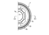
- FIG. 2A is a plan view showing a piston (valve disk) in the piston valve (valve) according to the embodiment of the present invention.
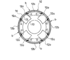
- FIG. 2B is a bottom view of the piston (valve disk) in the piston valve (valve) according to the embodiment of the present invention.
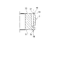
- 2C is a cross-sectional view taken along the line IIC-IIC in FIG. 2B.
- FIG. 3 is an enlarged view of a part of FIG. 2C.
- FIG. 1 is a longitudinal sectional view showing a main part of a shock absorber provided with a piston valve (valve) according to an embodiment of the present invention.
- FIG. 2A is a plan view showing a piston (valve disk) in the piston valve (valve) according to the embodiment of the present invention.
- FIG. 2B is a bottom view of the piston (
- FIG. 4 shows a boss portion and a seat of one piston that overlap each other when the piston (valve disk) in the piston valve (valve) according to the embodiment of the present invention is coaxially stacked. It is explanatory drawing which showed the state with which a sheet
- FIG. 5 is an explanatory view showing a process of attaching a piston ring to a piston (valve disk) in the piston valve (valve) according to the embodiment of the present invention.
- FIG. 6A is a plan view showing a piston (valve disk) in a piston valve (valve) according to a comparative example.
- FIG. 6B is a bottom view of a piston (valve disk) in a piston valve (valve) according to a comparative example.
- FIG. 6C is a cross-sectional view taken along the line VIC-VIC in FIG. 6B.
- FIG. 7 shows a state where a piston (valve disk) in a piston valve (valve) according to a comparative example is overlapped on the same axis, and a boss portion of one piston and a seat overlap with a seat of the other piston. It is explanatory drawing.
- the valve according to the present embodiment is embodied as a piston valve V of the shock absorber D.
- the piston valve V includes a piston (valve disk) 1 that partitions an extension side chamber (one chamber) A and a pressure side chamber (other chamber) B, and rings that are stacked on the extension side chamber A side and the pressure side chamber B side of the piston 1, respectively.
- the piston 1 is formed on the extending side chamber A side and the pressure side chamber B side, respectively, to form the annular boss portions 10 and 11 for supporting the leaf valves 2 and 3, and on the outer peripheral side of the boss portions 10 and 11, respectively.
- 2 and 3 seats 12 and 13, the opening portions 14 and 15 surrounded by the respective seats 12 and 13, and the extension side passages that communicate the extension side chamber A and the opening portion 15 on the compression side chamber B side (one side)
- a pressure side passage (the other passage) 5 that communicates the pressure side chamber B and the opening 14 on the extension side chamber A side.
- the pressure side chamber B side sheet 13 is disposed at a position higher than the boss portion 11 on the same side, that is, protrudes, and as shown in FIG. 3, the outer peripheral edge of the sheet 12 on the extension side chamber A side.
- the outer peripheral end t1 of the arc portion 12b is arranged on the outer peripheral side with respect to the outer peripheral end t3 of the sheet 13 on the compression side chamber B side.
- the “high position” in the piston 1 means that the piston 1 protrudes in the axial direction from the end face of the piston 1, and means that it is located on the side opposite to the piston from the comparative configuration.
- the “same side” in the piston 1 refers to the same end surface side of the piston 1 in the axial direction of the piston 1.
- the piston 1 includes an auxiliary seat 16 that is formed on the outer peripheral side of the seat 13 on the pressure side chamber B side and is disposed at substantially the same height as the seat 13.
- the “height” in the piston 1 means a positional relationship in the axial direction of the piston 1. That is, the “same height” in the piston 1 means that the axial position of the piston 1 is the same.
- the shock absorber D is, as shown in FIG. 1, a cylindrical cylinder C, a rod R that enters and exits the cylinder C, and a tip of the rod R that is held in the cylinder C in the axial direction.
- a movable piston valve V, an extension side chamber A formed on the rod R side of the piston valve V in the cylinder C, and a pressure side chamber B formed on the opposite rod side of the piston valve V in the cylinder C are provided.
- the extension side chamber A and the compression side chamber B are filled with hydraulic oil, but other fluids may be filled as long as a damping force can be generated.
- the shock absorber D includes a partition body such as a free piston or a bladder that divides an air chamber in which gas is enclosed and can be expanded and contracted, into the cylinder C.
- the change in the cylinder volume corresponding to the volume of the rod R entering and exiting C can be compensated.
- the configuration of the shock absorber D can be changed as appropriate.
- the shock absorber D includes an outer cylinder standing on the outer periphery of the cylinder C and is set to a double cylinder type.
- the reservoir is formed between the outer cylinder and the cylinder C and stores hydraulic oil. May be compensated.
- the shock absorber D includes a base valve that supplies the hydraulic oil corresponding to the volume of the rod entering and exiting the cylinder C from the reservoir to the cylinder C, and discharges the hydraulic oil from the cylinder C to the reservoir.
- This embodiment may be embodied.
- the shock absorber D is a single rod type shock absorber in which the rod R stands only on one side of the piston valve V, but the double rod type shock absorber in which the rod R stands on both sides of the piston valve V. It may be.
- the piston valve V includes an annular piston 1 that is a valve disk that partitions the expansion side chamber A and the pressure side chamber B, a plurality of annular plate-shaped leaf valves 2 stacked on the expansion side chamber A side of the piston 1, and a piston And a plurality of leaf valves 3 stacked on the one pressure side chamber B side.
- tip part in the rod R and smaller diameter than the other part is each penetrated by the piston 1 and the center hole 1a, 2a, 3a of each leaf valve 2,3, and an attachment part A nut N is screwed to the tip of r1.
- the piston valve V is held at the tip of the rod R.
- the number of leaf valves 2 and 3 stacked on the extension side chamber A side and the pressure side chamber B side is not limited to the figure, and can be changed as appropriate.
- the piston 1 has a smaller diameter than the cylinder C. On the outer periphery of the piston 1, a plurality of irregularities 1b and 1c are formed. A piston ring 6 made of synthetic resin is integrally attached to the outer periphery of the piston 1 by using these irregularities 1b and 1c.
- the piston 1 in the present embodiment is a molded piston. The piston 1 is in sliding contact with the inner peripheral surface of the cylinder C through the piston ring 6 and can move smoothly in the axial direction in the cylinder 1.
- the piston 1 includes an annular boss portion 10 formed on the extension side chamber A side which is the upper side in FIG. 2C and supporting the inner peripheral portion of the leaf valve 2 on the same side, and the boss portion 10 2 is formed on the pressure side chamber B side, which is the lower side in FIG. 2C, and the leaf on the same side.
- An annular boss portion 11 that supports the inner peripheral portion of the valve 3, a seat 13 that is formed on the outer peripheral side of the boss portion 11 and on which the outer peripheral portion of the leaf valve 3 is attached and detached, an opening 15 that is surrounded by the seat 13, and an extension A plurality of expansion side passages 4 communicating with the side chamber A and the opening 15 on the pressure side chamber B side, a plurality of pressure side passages 5 communicating with the pressure side chamber B and the opening 14 on the expansion side chamber A side, and the pressure side chamber B side And an auxiliary sheet 16 formed on the outer peripheral side of the sheet 13.
- the bosses 10 and 11 are support surfaces with which the leaf valves 2 and 3 abut, and the seats 12 and 13 are seat surfaces with which the leaf valves 2 and 3 are seated.
- the boss portion 10 on the extension side chamber A side is formed along the opening edge on the upper side in FIG. 2C of the center hole 1a.
- the sheet 12 formed on the outer peripheral side of the boss part 10 is formed in a petal shape, and connects the plurality of branch parts 12a radially extending from the boss part 10 to the outer peripheral side and the outer peripheral ends of the adjacent branch parts 12a.
- the boss part 10 and a plurality of arcuate arc parts 12b arranged at predetermined intervals are provided on the outer periphery of the part 10.
- the one branch part 12a is connected with the arc part 12b only with one branch part 12a among the branch parts 12a arrange
- Openings 14 are independently formed between the boss portion 10 on the extension side chamber A side, the arc portion 12b in the sheet 12 on the same side, and the pair of branch portions 12a connected by the arc portion 12b. Yes. A plurality of openings 14 are provided at predetermined intervals in the circumferential direction. Further, the leaf valve 2 on the extension side chamber A side is fixed to the rod R in a state in which the inner peripheral portion is seated on the boss portion 10 in the assembled state, and the outer peripheral portion is separable from the seat 12. For this reason, in the state where the outer peripheral portion of the leaf valve 2 is seated on the seat 12, the opening portion 14 is disconnected from the extension side chamber A by the leaf valve 2.
- the leaf valve 2 when the outer peripheral part of the leaf valve 2 bends to the anti-piston side and moves away from the seat 12, communication with the extension side chamber A is allowed. Since the pressure side passage 5 is connected to each opening 14 on the extension side chamber A side, the leaf valve 2 can allow or block the communication between the pressure side passage 5 and the extension side chamber A.
- the inner peripheral portion of the leaf valve 2 is not separated from the boss portion 10, but the assembly structure of the leaf valve 2 can be changed as appropriate.
- the inner peripheral portion of the leaf valve 2 may be separated from the boss portion 10.
- openings 17 are respectively formed between the pair of branch portions 12a that are not connected by the arc portion 12b in the sheet 12 on the same side on the outer peripheral side of the boss portion 10 on the extension side chamber A side.
- Each of the openings 17 is connected to the extending side passage 4. Even when the leaf valve 2 is seated on the seat 12, the communication between the opening 17 and the extension side chamber A is not blocked by the leaf valve 2. That is, the extension side passage 4 always communicates with the extension side chamber A through the opening 17.
- a plurality of openings 17 are provided at predetermined intervals in the circumferential direction.
- the boss portion 11 on the pressure side chamber B side is formed along the opening edge on the lower side in FIG. 2C of the center hole 1a.
- hub part 11 is formed in cyclic
- An annular opening 15 is formed between the boss 11 on the pressure side chamber B side and the sheet 13 on the same side. Further, the leaf valve 3 on the pressure side chamber B side is fixed to the rod R in a state in which the inner peripheral portion is seated on the boss portion 11 in the assembled state, and the outer peripheral portion can be separated from and seated on the seat 13. For this reason, in the state where the outer peripheral portion of the leaf valve 3 is seated on the seat 13, the opening 15 is disconnected from the pressure side chamber B by the leaf valve 3. On the other hand, when the outer peripheral portion of the leaf valve 3 bends to the anti-piston side and moves away from the seat 13, communication with the pressure side chamber B is allowed. Since the plurality of expansion side passages 4 are connected to the opening 15 on the compression side chamber B side, the leaf valve 3 can permit or block communication between the expansion side passage 4 and the compression side chamber B at the same time.
- the inner peripheral portion of the leaf valve 3 is not separated from the boss portion 11, but the assembly structure of the leaf valve 3 can be changed as appropriate.
- the inner peripheral portion of the leaf valve 3 may be separated from the boss portion 11.
- annular groove 1d is formed along the circumferential direction on the pressure side chamber B side of the outer periphery of the piston 1 with respect to the piston ring 6.
- the groove 1 d communicates with the pressure side passage 5. Even when the leaf valve 3 is seated on the seat 13, the groove 1 d is not blocked by the leaf valve 3 from the pressure side chamber B and is not blocked by the piston ring 6. . That is, the pressure side passage 5 is always in communication with the pressure side chamber B through the gap between the groove 1d and the cylinder C.
- the seat 13 on the pressure side chamber B side is disposed so as to protrude from the boss portion 11, and the initial deflection can be given to the leaf valve 3 seated on the seat 13.
- the shock absorber D in which the rod R is withdrawn from the cylinder C is extended, the extension side chamber A is pressurized, and the leaf valve 2 on the extension side chamber A side is pressed against the seat 12 on the same side so Block 5 Further, when the pressure in the expansion side chamber A reaches the valve opening pressure of the leaf valve 3 on the pressure side chamber B side, the outer peripheral portion of the leaf valve 3 bends to the anti-piston side and allows the expansion side passage 4 to communicate. Therefore, the shock absorber D generates an extension side damping force due to the resistance of the leaf valve 3 when the hydraulic oil passes through the extension side passage 4 and moves from the extension side chamber A to the compression side chamber B at the time of extension. To do. As described above, since the initial deflection is given to the leaf valve 3, the valve opening pressure of the leaf valve 3 can be increased.
- the shock absorber D in which the rod R enters the cylinder C, is compressed, the pressure side chamber B is pressurized, and the leaf valve 3 on the pressure side chamber B side is pressed against the seat 13 on the same side, so Cut off. Further, when the pressure in the pressure side chamber B reaches the valve opening pressure of the leaf valve 2 on the expansion side chamber A side, the outer peripheral portion of the leaf valve 2 bends to the anti-piston side, allowing the pressure side passage 5 to communicate. For this reason, the shock absorber D generates a compression-side damping force due to the resistance of the leaf valve 2 when the hydraulic oil passes through the compression-side passage 5 and moves from the compression-side chamber B to the expansion-side chamber A during compression.
- the outer peripheral end t1 of the arc portion 12b that is the outer peripheral end of the sheet 12 on the stretch side chamber A side and the inner peripheral end t2 of the arc portion 12b are both of the sheet 13 on the compression side chamber B side. It arrange
- the outer peripheral end t1 of the circular arc part 12b is an arcuate edge located on the outermost peripheral side in the circular arc part 12b.
- the inner peripheral end t2 of the arc part 12b is an arcuate edge located on the innermost side in the arc part 12b.
- the outer peripheral edge t3 of the sheet 13 is an annular edge located on the outermost side in the sheet 13.
- the auxiliary sheet 16 is formed in an annular shape on the outer periphery of the sheet 13 on the pressure side chamber B side, and is arranged with a predetermined gap from the sheet 13.
- the auxiliary sheet 16 is disposed at substantially the same height as the sheet 13.
- the outer peripheral end t4 of the auxiliary sheet 16 is disposed at substantially the same position as the outer peripheral end t1 of the sheet 12 (arc portion 12b) on the extension side chamber A side, and the inner peripheral end t5 of the auxiliary sheet 16 is the inner peripheral end of the arc portion 12b. It is disposed at substantially the same position as t2.
- the outer peripheral edge t4 of the auxiliary sheet 16 is an annular edge located on the outermost side of the auxiliary sheet 16.
- the inner peripheral end t5 of the auxiliary sheet 16 is an annular edge located on the innermost side in the auxiliary sheet 16.
- the boss portion 11 and the seat 13 on the compression side chamber B side there is a step between the boss portion 11 and the seat 13 on the compression side chamber B side, and when the plurality of pistons 1 are vertically stacked on the same axis, the boss portion of one piston 1 10 and the boss part 11 of the other piston 1 do not contact.
- the branch portion 12a of one of the overlapping pistons 1 comes into contact with the sheet 13 at a portion where the other piston 1 intersects with the sheet 13 and Since the entire arc portion 12b abuts on the auxiliary seat 16 of the other piston 1, the contact area of the overlapping pistons 1 can be increased.
- FIG. 4 is a diagram illustrating a state in which a plurality of pistons 1 are vertically stacked on the same axis and a boss portion 10 and a sheet 12 of one overlapping piston 1 overlap a sheet 13 and an auxiliary sheet 16 of the other piston 1.
- FIG. The hatched portions are shown in portions a and b where one piston 1 and the other piston 1 are in contact.
- the outer peripheral end t4 of the auxiliary sheet 16 is disposed at the same position as the outer peripheral end t1 of the arc portion 12b on the extension side chamber A side or on the outer peripheral side of the outer peripheral end t1, and the inner peripheral end t5 of the auxiliary sheet 16 is an arc portion. If the piston 1 is vertically stacked, the entire arc portion 12b of one piston 1 is supported by the other piston 1 when the piston 1 is vertically stacked if it is disposed at the same position as the inner peripheral end t2 of 12b or on the inner peripheral side of the inner peripheral end t2. It can be brought into contact with the sheet 16. Further, if the arc portion 12b of one piston 1 and the auxiliary sheet 16 of the other piston 1 can be brought into contact with each other, the auxiliary sheet 16 may be formed in an arc shape.
- the auxiliary sheet 16 may be arranged at a position higher than the sheet 13 on the compression side chamber B side, that is, so as to protrude.
- the branch portion 12a of one piston 1 and the seat 13 of the other piston 1 do not come into contact with each other, but the arc portion 12b of one piston 1 contacts the auxiliary seat 16. Since contact can be made, the contact area can be increased.
- the auxiliary seat 16 since the leaf valve 3 is not seated on the auxiliary seat 16, the auxiliary seat 16 does not affect the extension side damping force.
- FIG. 6A a piston valve (valve) according to a comparative example will be described with reference to FIGS. 6A, 6B, 6C, and 7.
- FIG. 6A, 6B, 6C, and 7 a piston valve (valve) according to a comparative example will be described with reference to FIGS. 6A, 6B, 6C, and 7.
- a sheet 72 formed on the extending side chamber side of the piston 7 is formed in a petal shape.
- the piston 7 includes a plurality of branch portions 72a extending from the boss portion 70 on the same side to the outer peripheral side, and a plurality of arc-shaped arc portions 72b connecting the outer peripheral ends of the branch portions 72a.
- the sheet 73 formed on the pressure side chamber side of the piston 7 is formed in an annular shape, and is arranged on the outer periphery of the boss portion 71 on the same side with a predetermined distance from the boss portion 71.
- outer peripheral end t6 and the inner peripheral end t7 of the arc portion 72b on the extension side chamber side are arranged on the outer peripheral side with respect to the outer peripheral end t8 of the compression side chamber side sheet 73, and the compression side chamber side sheet 73 is on the same side boss. It is arranged at a position higher than the portion 71 (on the opposite piston side).
- the leaf valve can be formed with a small diameter, the pressure receiving surface can be made smaller, and the expansion side damping force can be made larger than the compression side damping force. Therefore, when a shock absorber equipped with a piston valve having the above-described structure is interposed between the vehicle body and the wheel, the shock absorber extends after a thrust input from the road surface is applied with a low compression side damping force. When turning to the process, high extension side damping force can be exhibited.
- FIG. 7 is an explanatory view showing a state in which the sheet 73 of the other piston 7 overlaps the boss 70 and the sheet 72 of one overlapping piston 7 when the plurality of pistons 7 are vertically stacked on the same axis.
- the part a to be shown is hatched.
- the piston (valve disk) 1 is a molded piston integrated with an annular piston ring 6 attached to the outer periphery thereof.
- the piston (valve disk) 1 can smoothly move in the cylinder C by sliding the piston ring 6 on the inner peripheral surface of the cylinder C.
- the attachment method of the piston ring 6 is not limited to the above, and can be appropriately changed.
- the valve disk may be other than the piston, and the piston ring 6 may be eliminated.
- the auxiliary sheet 16 is formed in an annular shape, and is arranged on the outer periphery of the sheet 13 on the pressure side chamber (other chamber) B side with a predetermined distance from the sheet 13. Then, the outer peripheral end t4 of the auxiliary sheet 16 is disposed at substantially the same position as the outer peripheral end t1 of the arc portion 12b, and the inner peripheral end t5 of the auxiliary sheet 16 is disposed at substantially the same position as the inner peripheral end t2 of the arc portion 12b. Has been.
- the outer peripheral end t4 of the auxiliary sheet 16 is the same as the outer peripheral end t1 of the arc portion 12b or is arranged on the outer peripheral side of the outer peripheral end t1, and the inner peripheral end t5 of the auxiliary sheet 16 is the inner peripheral end of the arc portion 12b. If it is the same as t2 or arranged on the inner peripheral side with respect to the inner peripheral end t2, the above effect can be achieved.
- the shape of the auxiliary sheet 16 is not limited to the above, and may be formed in an arc shape or other shapes as long as the piston 1 can be brought into contact with the arc portion 12b when stacked.
- seat 12 of the extending side chamber (one chamber) A side is formed in the petal shape, and adjoins the several branch part 12a extended in the outer peripheral side from the boss
- both the sheets 12 and 13 of the piston (valve disk) 1 can be appropriately changed.
- both the sheets 12 and 13 may be formed in a ring shape or a petal shape.
- the piston (valve disk) 1 includes an auxiliary seat 16 that is formed on the outer peripheral side of the seat 13 on the pressure side chamber B side and is disposed at substantially the same height as the seat 13.
- the outer diameter of the seat 13 on the compression side chamber (the other chamber) B side is smaller than the outer diameter of the leaf valve 2 seated on the seat 12 on the extension side chamber (one chamber) A side, Since the outer diameter of the leaf valve 3 that is separated from the seat 13 on the pressure side chamber (the other chamber) B side is smaller than the outer diameter of the leaf valve 2 that is seated on the seat 12 on the extension side chamber (one chamber) A side, The side damping force can be increased compared to the compression side damping force.
- the auxiliary sheet 16 is disposed at substantially the same position as the sheet 13 on the pressure side chamber (other chamber) B side, but is disposed at the same position as the sheet 13 or higher than the sheet 13. It only has to be.
- the sheet 13 on the pressure side chamber (other chamber) B side is disposed at a position higher than the boss portion 11 on the pressure side chamber B side (same side), that is, so as to protrude.
- the sheet 12 on the extension side chamber (one chamber) A side may be arranged at a position higher than the boss part 10 on the extension side chamber A side (same side), and both the sheets 12 and 13 on both sides are the boss part on the same side. You may arrange
- the extension side chamber A is one chamber and the compression side chamber B is the other chamber, but the opposite may be possible.
- the compression side damping force can be made higher than the extension side damping force.
Landscapes
- Engineering & Computer Science (AREA)
- General Engineering & Computer Science (AREA)
- Mechanical Engineering (AREA)
- Fluid-Damping Devices (AREA)
Abstract
Description
Claims (4)
- バルブであって、
一方室と他方室とを区画するバルブディスクと、
前記バルブディスクの前記一方室側と前記他方室側にそれぞれ積層される環板状のリーフバルブと、を備え、
前記バルブディスクは、
前記一方室側と前記他方室側にそれぞれ形成されて前記リーフバルブを支える環状のボス部と、
前記一方室側と前記他方室側それぞれの前記ボス部の外周側に形成されて前記リーフバルブが離着座するシートと、
前記各シートで囲われる開口部と、
前記一方室と前記他方室側の前記開口部とを連通する一方通路と、
前記他方室と前記一方室側の前記開口部とを連通する他方通路と、を有し、
前記一方室側及び前記他方室側の前記シートの少なくとも一方は、前記ボス部よりも突出するように配置され、
前記一方室側の前記シートの外周端が前記他方室側の前記シートの外周端よりも外周側に配置され、
前記バルブディスクは、前記他方室側の前記シートの外周側に形成され前記他方室側の前記シートと同じ高さ、あるいは、前記他方室側の前記シートより突出する補助シートを有するバルブ。 - 請求項1に記載のバルブであって、
前記一方室側の前記シートは、前記一方室側の前記ボス部から外周側に延びる複数の枝部と、隣り合う前記枝部の外周端をつなぐ複数の円弧状の円弧部と、を備えるバルブ。 - 請求項2に記載のバルブであって、
前記補助シートは、環状に形成され、前記他方室側の前記シートの外周に、前記他方室側の前記シートと所定の間隔を開けて配置されており、
前記補助シートの外周端が前記円弧部の外周端と同じか、前記円弧部の前記外周端よりも外周側に配置されるとともに、前記補助シートの内周端が前記円弧部の内周端と同じか、前記円弧部の前記内周端よりも内周側に配置されているバルブ。 - 請求項1に記載のバルブであって、
前記バルブディスクは、その外周に取り付けられる環状のピストンリングと一体化されたモールドピストンであるバルブ。
Priority Applications (3)
| Application Number | Priority Date | Filing Date | Title |
|---|---|---|---|
| US15/030,441 US10138976B2 (en) | 2013-11-08 | 2014-09-26 | Valve |
| DE112014005104.7T DE112014005104T5 (de) | 2013-11-08 | 2014-09-26 | Ventil |
| CN201480057430.5A CN105658988B (zh) | 2013-11-08 | 2014-09-26 | 阀 |
Applications Claiming Priority (2)
| Application Number | Priority Date | Filing Date | Title |
|---|---|---|---|
| JP2013232139A JP5783646B2 (ja) | 2013-11-08 | 2013-11-08 | バルブ |
| JP2013-232139 | 2013-11-08 |
Publications (1)
| Publication Number | Publication Date |
|---|---|
| WO2015068489A1 true WO2015068489A1 (ja) | 2015-05-14 |
Family
ID=53041272
Family Applications (1)
| Application Number | Title | Priority Date | Filing Date |
|---|---|---|---|
| PCT/JP2014/075583 Ceased WO2015068489A1 (ja) | 2013-11-08 | 2014-09-26 | バルブ |
Country Status (5)
| Country | Link |
|---|---|
| US (1) | US10138976B2 (ja) |
| JP (1) | JP5783646B2 (ja) |
| CN (1) | CN105658988B (ja) |
| DE (1) | DE112014005104T5 (ja) |
| WO (1) | WO2015068489A1 (ja) |
Families Citing this family (5)
| Publication number | Priority date | Publication date | Assignee | Title |
|---|---|---|---|---|
| JP6642207B2 (ja) * | 2016-03-30 | 2020-02-05 | 株式会社ショーワ | 緩衝器、及び減衰力発生装置 |
| DE102016223497A1 (de) * | 2016-11-28 | 2018-05-30 | Volkswagen Aktiengesellschaft | Ventileinheit und Kompressor mit einer solchen Ventileinheit |
| DE102017010876B4 (de) * | 2017-11-24 | 2023-06-01 | Günther Zimmer | Zylinder-Kolben-Einheit mit lastabhängiger Drossel |
| US11255399B2 (en) * | 2018-03-14 | 2022-02-22 | Zf Friedrichshafen Ag | Damping valve for a vibration damper |
| JP2025047262A (ja) * | 2023-09-21 | 2025-04-03 | カヤバ株式会社 | バルブおよび緩衝器 |
Citations (3)
| Publication number | Priority date | Publication date | Assignee | Title |
|---|---|---|---|---|
| JPH03199732A (ja) * | 1989-12-27 | 1991-08-30 | Kayaba Ind Co Ltd | 油圧緩衝器のバルブ装置 |
| JP2001082526A (ja) * | 1999-09-17 | 2001-03-27 | Kayaba Ind Co Ltd | 油圧緩衝器用モールドピストンの製造方法 |
| JP2012229784A (ja) * | 2011-04-27 | 2012-11-22 | Hitachi Automotive Systems Ltd | 緩衝器 |
Family Cites Families (13)
| Publication number | Priority date | Publication date | Assignee | Title |
|---|---|---|---|---|
| US2648405A (en) * | 1949-12-17 | 1953-08-11 | Patent Dev Company | Piston assembly for shock absorbers |
| JP3009151B2 (ja) * | 1988-04-04 | 2000-02-14 | 株式会社ユニシアジェックス | 液圧緩衝器 |
| JPH02168038A (ja) * | 1988-09-30 | 1990-06-28 | Tokico Ltd | 油圧緩衝器 |
| GB2226620B (en) * | 1988-10-25 | 1992-11-04 | Tokico Ltd | Hydraulic damper |
| US5226512A (en) * | 1989-02-22 | 1993-07-13 | Atsugi Unisia Corporation | Variable damping force shock absorber with variable orifice for adjusting damping characteristics |
| US5219414A (en) * | 1989-04-24 | 1993-06-15 | Atsugi Unisia Corporation | Variable damping force shock absorber with stroke dependent variation characteristics of damping force |
| SE9602507L (sv) * | 1996-06-25 | 1997-12-26 | Oehlins Racing Ab | Stötdämpare |
| JP5115814B2 (ja) * | 2008-05-30 | 2013-01-09 | 日立オートモティブシステムズ株式会社 | 緩衝器 |
| CN101857036B (zh) * | 2009-04-10 | 2012-07-25 | 萱场工业株式会社 | 铁道车辆用线性减震器 |
| JP5941359B2 (ja) * | 2012-07-10 | 2016-06-29 | Kyb株式会社 | 緩衝器のバルブ構造 |
| JP6014444B2 (ja) * | 2012-09-28 | 2016-10-25 | 日立オートモティブシステムズ株式会社 | 緩衝器 |
| JP6071646B2 (ja) * | 2012-11-30 | 2017-02-01 | 日立オートモティブシステムズ株式会社 | 緩衝器 |
| NL2010038C2 (en) * | 2012-12-21 | 2014-06-24 | Koni Bv | Shock absorber. |
-
2013
- 2013-11-08 JP JP2013232139A patent/JP5783646B2/ja active Active
-
2014
- 2014-09-26 WO PCT/JP2014/075583 patent/WO2015068489A1/ja not_active Ceased
- 2014-09-26 CN CN201480057430.5A patent/CN105658988B/zh active Active
- 2014-09-26 DE DE112014005104.7T patent/DE112014005104T5/de not_active Withdrawn
- 2014-09-26 US US15/030,441 patent/US10138976B2/en not_active Expired - Fee Related
Patent Citations (3)
| Publication number | Priority date | Publication date | Assignee | Title |
|---|---|---|---|---|
| JPH03199732A (ja) * | 1989-12-27 | 1991-08-30 | Kayaba Ind Co Ltd | 油圧緩衝器のバルブ装置 |
| JP2001082526A (ja) * | 1999-09-17 | 2001-03-27 | Kayaba Ind Co Ltd | 油圧緩衝器用モールドピストンの製造方法 |
| JP2012229784A (ja) * | 2011-04-27 | 2012-11-22 | Hitachi Automotive Systems Ltd | 緩衝器 |
Also Published As
| Publication number | Publication date |
|---|---|
| US20160245361A1 (en) | 2016-08-25 |
| CN105658988B (zh) | 2018-07-13 |
| US10138976B2 (en) | 2018-11-27 |
| DE112014005104T5 (de) | 2016-09-01 |
| JP2015094378A (ja) | 2015-05-18 |
| CN105658988A (zh) | 2016-06-08 |
| JP5783646B2 (ja) | 2015-09-24 |
Similar Documents
| Publication | Publication Date | Title |
|---|---|---|
| WO2015068489A1 (ja) | バルブ | |
| JP6466905B2 (ja) | 面シールおよび圧力逃がしポートを備える2位置弁 | |
| US20140150897A1 (en) | Shock absorber | |
| US10183657B2 (en) | Master cylinder | |
| JP5325763B2 (ja) | 緩衝器 | |
| JP5783647B2 (ja) | バルブ | |
| WO2018163444A1 (ja) | 圧力緩衝装置 | |
| JP6487804B2 (ja) | 緩衝器のバルブ構造 | |
| US10253840B2 (en) | Cylinder apparatus | |
| JP2008138696A (ja) | 油圧緩衝器の分割ピストン構造 | |
| US9772000B2 (en) | Piston and shock absorber including piston | |
| CN104903610A (zh) | 缓冲器 | |
| JP6628143B2 (ja) | 弁機構、減衰力発生装置、及び緩衝器 | |
| CN103363009B (zh) | 液压缓冲器的阻尼力产生装置以及前叉 | |
| JP6628144B2 (ja) | 弁機構、減衰力発生装置、及び緩衝器 | |
| JP6628145B2 (ja) | 弁機構、減衰力発生装置、及び緩衝器 | |
| JP5764054B2 (ja) | バルブ装置 | |
| JP2020056484A (ja) | フロントフォーク | |
| WO2019189560A1 (ja) | バルブシート部材、バルブ、及び緩衝器 | |
| WO2020026362A1 (ja) | 弁機構および緩衝器 | |
| US20250109778A1 (en) | Piston for buffer device and buffer device | |
| JP6006621B2 (ja) | 緩衝器 | |
| JP6594790B2 (ja) | 圧力緩衝装置 | |
| JP6401862B2 (ja) | ピストン | |
| KR20200141743A (ko) | 쇽업소버 |
Legal Events
| Date | Code | Title | Description |
|---|---|---|---|
| 121 | Ep: the epo has been informed by wipo that ep was designated in this application |
Ref document number: 14860170 Country of ref document: EP Kind code of ref document: A1 |
|
| WWE | Wipo information: entry into national phase |
Ref document number: 15030441 Country of ref document: US |
|
| WWE | Wipo information: entry into national phase |
Ref document number: 112014005104 Country of ref document: DE Ref document number: 1120140051047 Country of ref document: DE |
|
| 122 | Ep: pct application non-entry in european phase |
Ref document number: 14860170 Country of ref document: EP Kind code of ref document: A1 |