WO2015068375A1 - 燃料供給装置 - Google Patents
燃料供給装置 Download PDFInfo
- Publication number
- WO2015068375A1 WO2015068375A1 PCT/JP2014/005536 JP2014005536W WO2015068375A1 WO 2015068375 A1 WO2015068375 A1 WO 2015068375A1 JP 2014005536 W JP2014005536 W JP 2014005536W WO 2015068375 A1 WO2015068375 A1 WO 2015068375A1
- Authority
- WO
- WIPO (PCT)
- Prior art keywords
- fuel
- valve
- passage
- case
- residual pressure
- Prior art date
- Legal status (The legal status is an assumption and is not a legal conclusion. Google has not performed a legal analysis and makes no representation as to the accuracy of the status listed.)
- Ceased
Links
Images







Classifications
-
- F—MECHANICAL ENGINEERING; LIGHTING; HEATING; WEAPONS; BLASTING
- F02—COMBUSTION ENGINES; HOT-GAS OR COMBUSTION-PRODUCT ENGINE PLANTS
- F02M—SUPPLYING COMBUSTION ENGINES IN GENERAL WITH COMBUSTIBLE MIXTURES OR CONSTITUENTS THEREOF
- F02M37/00—Apparatus or systems for feeding liquid fuel from storage containers to carburettors or fuel-injection apparatus; Arrangements for purifying liquid fuel specially adapted for, or arranged on, internal-combustion engines
- F02M37/04—Feeding by means of driven pumps
- F02M37/08—Feeding by means of driven pumps electrically driven
- F02M37/10—Feeding by means of driven pumps electrically driven submerged in fuel, e.g. in reservoir
- F02M37/106—Feeding by means of driven pumps electrically driven submerged in fuel, e.g. in reservoir the pump being installed in a sub-tank
-
- F—MECHANICAL ENGINEERING; LIGHTING; HEATING; WEAPONS; BLASTING
- F02—COMBUSTION ENGINES; HOT-GAS OR COMBUSTION-PRODUCT ENGINE PLANTS
- F02M—SUPPLYING COMBUSTION ENGINES IN GENERAL WITH COMBUSTIBLE MIXTURES OR CONSTITUENTS THEREOF
- F02M37/00—Apparatus or systems for feeding liquid fuel from storage containers to carburettors or fuel-injection apparatus; Arrangements for purifying liquid fuel specially adapted for, or arranged on, internal-combustion engines
- F02M37/04—Feeding by means of driven pumps
- F02M37/14—Feeding by means of driven pumps the pumps being combined with other apparatus
-
- F—MECHANICAL ENGINEERING; LIGHTING; HEATING; WEAPONS; BLASTING
- F02—COMBUSTION ENGINES; HOT-GAS OR COMBUSTION-PRODUCT ENGINE PLANTS
- F02M—SUPPLYING COMBUSTION ENGINES IN GENERAL WITH COMBUSTIBLE MIXTURES OR CONSTITUENTS THEREOF
- F02M37/00—Apparatus or systems for feeding liquid fuel from storage containers to carburettors or fuel-injection apparatus; Arrangements for purifying liquid fuel specially adapted for, or arranged on, internal-combustion engines
- F02M37/0011—Constructional details; Manufacturing or assembly of elements of fuel systems; Materials therefor
- F02M37/0023—Valves in the fuel supply and return system
- F02M37/0029—Pressure regulator in the low pressure fuel system
-
- F—MECHANICAL ENGINEERING; LIGHTING; HEATING; WEAPONS; BLASTING
- F02—COMBUSTION ENGINES; HOT-GAS OR COMBUSTION-PRODUCT ENGINE PLANTS
- F02M—SUPPLYING COMBUSTION ENGINES IN GENERAL WITH COMBUSTIBLE MIXTURES OR CONSTITUENTS THEREOF
- F02M37/00—Apparatus or systems for feeding liquid fuel from storage containers to carburettors or fuel-injection apparatus; Arrangements for purifying liquid fuel specially adapted for, or arranged on, internal-combustion engines
- F02M37/02—Feeding by means of suction apparatus, e.g. by air flow through carburettors
- F02M37/025—Feeding by means of a liquid fuel-driven jet pump
-
- F—MECHANICAL ENGINEERING; LIGHTING; HEATING; WEAPONS; BLASTING
- F02—COMBUSTION ENGINES; HOT-GAS OR COMBUSTION-PRODUCT ENGINE PLANTS
- F02M—SUPPLYING COMBUSTION ENGINES IN GENERAL WITH COMBUSTIBLE MIXTURES OR CONSTITUENTS THEREOF
- F02M37/00—Apparatus or systems for feeding liquid fuel from storage containers to carburettors or fuel-injection apparatus; Arrangements for purifying liquid fuel specially adapted for, or arranged on, internal-combustion engines
- F02M37/22—Arrangements for purifying liquid fuel specially adapted for, or arranged on, internal-combustion engines, e.g. arrangements in the feeding system
-
- F—MECHANICAL ENGINEERING; LIGHTING; HEATING; WEAPONS; BLASTING
- F02—COMBUSTION ENGINES; HOT-GAS OR COMBUSTION-PRODUCT ENGINE PLANTS
- F02M—SUPPLYING COMBUSTION ENGINES IN GENERAL WITH COMBUSTIBLE MIXTURES OR CONSTITUENTS THEREOF
- F02M37/00—Apparatus or systems for feeding liquid fuel from storage containers to carburettors or fuel-injection apparatus; Arrangements for purifying liquid fuel specially adapted for, or arranged on, internal-combustion engines
- F02M37/22—Arrangements for purifying liquid fuel specially adapted for, or arranged on, internal-combustion engines, e.g. arrangements in the feeding system
- F02M37/32—Arrangements for purifying liquid fuel specially adapted for, or arranged on, internal-combustion engines, e.g. arrangements in the feeding system characterised by filters or filter arrangements
- F02M37/44—Filters structurally associated with pumps
-
- F—MECHANICAL ENGINEERING; LIGHTING; HEATING; WEAPONS; BLASTING
- F02—COMBUSTION ENGINES; HOT-GAS OR COMBUSTION-PRODUCT ENGINE PLANTS
- F02M—SUPPLYING COMBUSTION ENGINES IN GENERAL WITH COMBUSTIBLE MIXTURES OR CONSTITUENTS THEREOF
- F02M37/00—Apparatus or systems for feeding liquid fuel from storage containers to carburettors or fuel-injection apparatus; Arrangements for purifying liquid fuel specially adapted for, or arranged on, internal-combustion engines
- F02M37/22—Arrangements for purifying liquid fuel specially adapted for, or arranged on, internal-combustion engines, e.g. arrangements in the feeding system
- F02M37/32—Arrangements for purifying liquid fuel specially adapted for, or arranged on, internal-combustion engines, e.g. arrangements in the feeding system characterised by filters or filter arrangements
- F02M37/46—Filters structurally associated with pressure regulators
-
- F—MECHANICAL ENGINEERING; LIGHTING; HEATING; WEAPONS; BLASTING
- F02—COMBUSTION ENGINES; HOT-GAS OR COMBUSTION-PRODUCT ENGINE PLANTS
- F02M—SUPPLYING COMBUSTION ENGINES IN GENERAL WITH COMBUSTIBLE MIXTURES OR CONSTITUENTS THEREOF
- F02M37/00—Apparatus or systems for feeding liquid fuel from storage containers to carburettors or fuel-injection apparatus; Arrangements for purifying liquid fuel specially adapted for, or arranged on, internal-combustion engines
- F02M37/22—Arrangements for purifying liquid fuel specially adapted for, or arranged on, internal-combustion engines, e.g. arrangements in the feeding system
- F02M37/32—Arrangements for purifying liquid fuel specially adapted for, or arranged on, internal-combustion engines, e.g. arrangements in the feeding system characterised by filters or filter arrangements
- F02M37/50—Filters arranged in or on fuel tanks
-
- F—MECHANICAL ENGINEERING; LIGHTING; HEATING; WEAPONS; BLASTING
- F02—COMBUSTION ENGINES; HOT-GAS OR COMBUSTION-PRODUCT ENGINE PLANTS
- F02M—SUPPLYING COMBUSTION ENGINES IN GENERAL WITH COMBUSTIBLE MIXTURES OR CONSTITUENTS THEREOF
- F02M37/00—Apparatus or systems for feeding liquid fuel from storage containers to carburettors or fuel-injection apparatus; Arrangements for purifying liquid fuel specially adapted for, or arranged on, internal-combustion engines
- F02M37/04—Feeding by means of driven pumps
- F02M37/12—Feeding by means of driven pumps fluid-driven, e.g. by compressed combustion-air
-
- F—MECHANICAL ENGINEERING; LIGHTING; HEATING; WEAPONS; BLASTING
- F02—COMBUSTION ENGINES; HOT-GAS OR COMBUSTION-PRODUCT ENGINE PLANTS
- F02M—SUPPLYING COMBUSTION ENGINES IN GENERAL WITH COMBUSTIBLE MIXTURES OR CONSTITUENTS THEREOF
- F02M37/00—Apparatus or systems for feeding liquid fuel from storage containers to carburettors or fuel-injection apparatus; Arrangements for purifying liquid fuel specially adapted for, or arranged on, internal-combustion engines
- F02M37/22—Arrangements for purifying liquid fuel specially adapted for, or arranged on, internal-combustion engines, e.g. arrangements in the feeding system
- F02M37/32—Arrangements for purifying liquid fuel specially adapted for, or arranged on, internal-combustion engines, e.g. arrangements in the feeding system characterised by filters or filter arrangements
- F02M37/34—Arrangements for purifying liquid fuel specially adapted for, or arranged on, internal-combustion engines, e.g. arrangements in the feeding system characterised by filters or filter arrangements by the filter structure, e.g. honeycomb, mesh or fibrous
Definitions
- the present disclosure relates to a fuel supply device that supplies fuel in a fuel tank to an internal combustion engine side.
- a fuel supply device that supplies fuel pumped from a fuel tank by a fuel pump through a fuel filter in a filter case and supplies the fuel from the case to the internal combustion engine side is widely used by being mounted on a vehicle. ing.
- a filter case is illustrated as being configured from a bottomed case body that forms a fuel filter housing chamber and a case cap that covers an opening of the case body. Yes.
- the residual pressure holding valve is assembled to the case body from the bottom side.
- the present disclosure has been made in view of the above points, and an object of the present disclosure is to improve the productivity of a fuel supply device that exhibits a function of maintaining the residual pressure of fuel supplied to the internal combustion engine.
- the first disclosure includes a fuel pump and a filter case that accommodates a fuel filter, and the fuel pumped from the fuel tank by the fuel pump is filtered by the fuel filter and supplied from the filter case to the internal combustion engine side.
- the filter case includes a bottomed case body that forms a fuel filter housing chamber, a case cap that covers the opening of the case body by being joined to the case body, and a case A residual pressure holding valve which is provided at a boundary between the main body and the case cap and holds the pressure of the fuel supplied from the inside of the filter case to the internal combustion engine side when the fuel pump is stopped.
- the residual pressure holding valve is provided at the junction boundary between the bottomed case main body and the case cap, so that the case cap is assembled to the case main body and the residual pressure holding valve to the case main body. Can be implemented at a common location. Therefore, it is possible to improve the productivity of the fuel supply device that exhibits the function of holding the residual pressure of the fuel supplied to the internal combustion engine by the residual pressure holding valve.
- the residual pressure holding valve is joined to the case body and the case cap and forms a valve seat, and is accommodated in the valve housing so as to be separable from the valve seat.
- a valve element that holds the pressure of the fuel supplied to the internal combustion engine side by being seated on the valve seat is combined.
- the valve housing that houses the valve element in the residual pressure holding valve of the second disclosure is joined to the case body and the case cap at the joining boundary between the case body and the case cap. Therefore, by performing the operation of joining the valve housing to the case main body and the case cap, the assembly of the case cap to the case main body and the assembly of the residual pressure holding valve to the case main body can be realized simultaneously at a common location.
- the valve element is seated on the valve seat of the valve housing as the fuel pump stops, so that the pressure of the fuel supplied to the internal combustion engine can be reliably maintained. As a result, the productivity of the fuel supply device can be increased together with the reliability of the residual pressure holding function.
- valve housing is joined on a virtual plane common to the case body and the case cap.
- the joint of the valve housing with the case main body and the case cap is performed on a common virtual plane, so that not only the joining work is facilitated but also poor joining is less likely to occur. According to this, it becomes possible to increase the yield as well as the productivity of the fuel supply device.
- the residual pressure holding valve is a springless external residual pressure holding valve that holds the pressure of the fuel supplied to the internal combustion engine side when the fuel pump is stopped, and opens when the fuel pump operates.
- an external residual pressure holding valve having a valve element that is locked to the valve stopper, and has a communication port that communicates with the storage chamber on the downstream side of the fuel filter, from the communication port toward the internal combustion engine side.
- a fuel passage for distributing the fuel to be discharged is provided in the filter case, and as a spring-biased internal residual pressure holding valve that holds the fuel pressure in the storage chamber with the stoppage of the fuel pump, with the operation of the fuel pump
- An internal residual pressure holding valve having a valve element that opens against the spring reaction force is provided in the filter case, and the communication port is an internal residual pressure in the fuel passage.
- An external passage portion that opens at a misaligned position from the holding valve toward the external residual pressure holding valve and allows fuel to be discharged toward the internal combustion engine to flow from the communication port toward the external residual pressure holding valve
- the internal passage portion that restricts the flow of fuel flowing from the communication port toward the internal residual pressure holding valve side than the external passage portion is formed in the fuel passage, and the cross-sectional area of the internal passage portion is cylindrical.
- the external residual pressure holding valve is a springless type having a valve element that is opened by the operation of the fuel pump and locked to the valve stopper. Therefore, even if pressure pulsation occurs due to fuel pumping from the fuel pump, the locked valve element is unlikely to vibrate.
- the internal residual pressure holding valve is a spring-biased type having a valve element that opens against a spring reaction force when the fuel pump is operated.
- the communication port communicating with the storage chamber on the downstream side of the fuel filter is displaced from the internal residual pressure holding valve to the external residual pressure holding valve side. Open at the position of the misalignment.
- the internal passage portion that restricts the fuel flow from the communication port to the internal residual pressure holding valve side rather than the external passage portion from which the fuel flows from the communication port to the external residual pressure holding valve side the above-mentioned L
- the length L can be increased so as to satisfy the relational expression / D ⁇ 3.
- the pressure pulsation generated by the fuel pumping from the fuel pump can be attenuated in the internal passage portion that is narrowed down to the spring-biased internal residual pressure holding valve.
- the vibration of the valve element at the valve can also be damped.
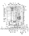
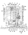
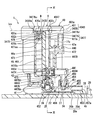
- FIG. 4 is a view showing the pump unit of FIG. 1 and is a cross-sectional view taken along line II-II of FIG.
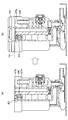
- FIG. 1st embodiment it is a schematic diagram explaining the assembly
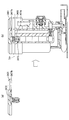
- 2nd embodiment it is a schematic diagram explaining the assembly
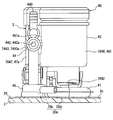
- FIG. 12 is a view corresponding to FIG. 2 showing a pump unit of a fuel supply device according to a fourth embodiment, and is a cross-sectional view taken along the line IX-IX in FIG. 11.
- FIG. 10 is a sectional view taken along line XX in FIG. 9. It is a top view which shows the pump unit of FIG. It is a top view which shows the pump unit of the fuel supply apparatus by 5th embodiment. It is sectional drawing which shows the modification of FIG. FIG.
- FIG. 17 is a view showing a fuel supply device according to a sixth embodiment, and is a cross-sectional view taken along line XIV-XIV in FIG. 16.
- FIG. 17 is a diagram showing the pump unit of FIG. 14 and is a cross-sectional view taken along line XV-XV of FIG. It is the XVI-XVI sectional view taken on the line of FIG. It is a fragmentary sectional view which shows the fuel supply apparatus of FIG.
- It is a schematic diagram for demonstrating the fuel supply apparatus by 6th embodiment. It is a characteristic view for demonstrating the effect of the fuel supply apparatus by 6th embodiment. It is a characteristic view for demonstrating the effect of the fuel supply apparatus by 6th embodiment.
- the device 1 supplies the fuel in the fuel tank 2 directly to the fuel injection valve of the internal combustion engine 3 or indirectly through a high-pressure pump or the like.
- the fuel tank 2 on which the apparatus 1 is mounted is formed in a hollow shape with resin or metal, and stores fuel to be supplied to the internal combustion engine 3 side.
- the internal combustion engine 3 that supplies fuel from the device 1 may be a gasoline engine or a diesel engine.
- the vertical direction of the device 1 shown in FIGS. 1 and 2 substantially coincides with the vertical direction of the vehicle on a horizontal plane.
- the apparatus 1 includes a flange 10, a sub tank 20, an adjustment mechanism 30, and a pump unit 40.
- the flange 10 is formed in a disk shape with resin and is attached to the top plate portion 2 a of the fuel tank 2.
- the flange 10 closes the through hole 2b formed in the portion 2a by sandwiching the packing 10a between the flange 10 and the top plate portion 2a.
- the flange 10 integrally includes a fuel supply pipe 12 and an electrical connector 14.
- the fuel supply pipe 12 protrudes upward and downward from the flange 10.
- the fuel supply pipe 12 communicates with the pump unit 40 via a flexible tube 12a that can be bent. With this communication mode, the fuel supply pipe 12 supplies the fuel pumped from the fuel tank 2 by the fuel pump 42 of the pump unit 40 to the internal combustion engine 3 side outside the fuel tank 2.
- the electrical connector 14 also protrudes upward and downward from the flange 10. The electrical connector 14 electrically connects the fuel pump 42 to an external circuit (not shown). With this electrical connection, the fuel pump 42 is controlled by an external circuit.
- the sub tank 20 is formed of a resin into a bottomed cylindrical shape and is accommodated in the fuel tank 2.
- the bottom 20 a of the sub tank 20 is placed on the bottom 2 c of the fuel tank 2.
- a concave bottom portion 20b that is recessed upward in the bottom portion 20a secures an inflow space 22 between the bottom portion 2c.
- inflow ports 24 and 25 are formed in the concave bottom portion 20b. The inflow ports 24 and 25 communicate with the fuel tank 2 through the inflow space 22. Under such a communication mode, the one inlet 24 allows the fuel that the jet pump 45 of the pump unit 40 transfers from the fuel tank 2 to flow into the sub tank 20.
- the other inflow port 25 allows fuel oil supplied into the tank 2 to flow into the sub tank 20 when fueling the empty fuel tank 2.
- the fuel flowing in through the inlets 24 and 25 is stored in the internal space 26 (see also FIG. 1) of the sub tank 20 including the periphery of the fuel pump 42.
- a reed valve 27 that opens the inlet 24 when a negative pressure from the jet pump 45, which will be described in detail later, and an inlet 25 are opened when the hydraulic pressure is applied.
- a reed valve 28 is provided.
- the adjusting mechanism 30 includes a holding member 32, a pair of support posts 34, an elastic member 36, and the like.
- the holding member 32 is formed in an annular shape with resin, and is mounted on the upper portion 20 c of the sub tank 20 in the fuel tank 2.
- Each column 34 is formed of a metal in a cylindrical shape, is accommodated in the fuel tank 2, and extends in the vertical direction. The upper end portion of each column 34 is fixed to the flange 10. Below each upper end, each column 34 is slidably guided in the vertical direction by the holding member 32 in a state of entering the sub tank 20.
- the elastic member 36 is formed of a metal in a coil spring shape and is accommodated in the fuel tank 2.
- the elastic member 36 is coaxially disposed around the corresponding one column 34.
- the elastic member 36 is interposed between the corresponding column 34 and the holding member 32 in the vertical direction.
- the elastic member 36 presses the bottom portion 20a of the sub tank 20 toward the bottom portion 2c of the fuel tank 2 through the holding member 32 by such an interposition form.
- the pump unit 40 is accommodated in the fuel tank 2.
- the pump unit 40 includes a suction filter 41, a fuel pump 42, a filter case 43, a port member 44, a jet pump 45, and the like.
- the suction filter 41 is, for example, a nonwoven fabric filter or the like, and is placed on the bottom 20a in the sub tank 20.
- the suction filter 41 filters the fuel sucked into the fuel pump 42 from the internal space 26 of the sub tank 20, thereby removing large foreign matters in the suction target fuel.
- the fuel pump 42 is disposed above the suction filter 41 in the sub tank 20.
- the cylindrical fuel pump 42 as a whole has its axial direction substantially aligned with the vertical direction.
- the fuel pump 42 is an electric pump.
- the fuel pump 42 is electrically connected to the electrical connector 14 via a flexible wiring 42a that can be bent.
- the fuel pump 42 operates by receiving drive control from an external circuit through the electrical connector 14.
- the operating fuel pump 42 sucks the fuel stored around it through the suction filter 41, and further regulates the sucked fuel by internal pressurization.
- the fuel pump 42 has a delivery valve 421 integrally with a delivery port 420 that delivers fuel.
- the delivery valve 421 is a springless check valve. While the fuel is pressurized with the operation of the fuel pump 42, the delivery valve 421 is opened. When the valve is opened, fuel is pumped from the delivery port 420 into the filter case 43. On the other hand, when the pressurization of the fuel is stopped as the fuel pump 42 is stopped, the delivery valve 421 is closed. When the valve is closed, the fuel pumping into the filter case 43 is also stopped.
- the filter case 43 is formed in a hollow shape with resin, and is arranged across the inside and outside of the sub tank 20 in the vertical direction.
- the filter case 43 is positioned with respect to the sub tank 20 by being held by the holding member 32.
- the accommodating portion 46 of the filter case 43 is formed in a double cylindrical shape from the inner cylindrical portion 460 and the outer cylindrical portion 461, and is disposed coaxially around the fuel pump 42.
- the axial direction of the filter case 43 is along the up-and-down direction due to the arrangement form of the accommodating portions 46.
- the accommodating portion 46 forms a communication chamber 462 communicating with the delivery port 420 above the inner cylinder portion 460 and the outer cylinder portion 461 in a flat space shape.
- the accommodating portion 46 forms an accommodating chamber 463 that communicates with the communication chamber 462 between the inner cylinder portion 460 and the outer cylinder portion 461 in a cylindrical hole shape.
- a cylindrical fuel filter 464 is accommodated in the accommodation chamber 463.
- the fuel filter 464 is a honeycomb filter or the like, for example, and removes fine foreign matters in the pressurized fuel by filtering the pressurized fuel sent from the delivery port 420 to the accommodation chamber 463 via the communication chamber 462. .
- the protrusion 47 of the filter case 43 protrudes in the radially outward direction from the outer tube portion 461 toward the specific portion S in the circumferential direction.
- a fuel passage 470, a partition wall 471, a discharge passage 472, an external residual pressure holding valve 473, a branch passage 474, an internal residual pressure holding valve 475, and a relief passage 476 are housed in the protrusion 47.
- the protrusion 47 has the elements 470, 471, 472, 473, 474, 475, and 476 integrally with the specific portion S in the circumferential direction.
- the fuel passage 470 is formed in a space that extends the protrusion 47 in an inverted U shape.
- the fuel passage 470 is partitioned by a partition wall 471 so that it is folded back in the axial direction of the filter case 43 along the vertical direction.
- the fuel passage 470 is linearly partitioned by a flat strip-like partition wall 471.
- the upstream straight portion 470b and the downstream straight portion 470c respectively extend downward from both ends of the uppermost folded portion 470a into a straight, substantially rectangular hole shape.
- the fuel passage 470 is constituted by the folded portion 470a, the upstream straight portion 470b at a location upstream from the portion 470a, and the downstream straight portion 470c at a location downstream from the portion 470a.
- the fuel passage 470 is disposed downstream of the fuel filter 464 by connecting the upstream straight portion 470b to the fuel outlet 463a of the storage chamber 463 as shown in FIGS.
- the fuel passage 470 having such an arrangement allows the pressurized fuel filtered by the fuel filter 464 and led out from the fuel outlet 463a to flow toward the most downstream end 470d side of the downstream straight portion 470c.
- the discharge passage 472 is formed in a cylindrical shape at an intermediate portion in the vertical direction of the protrusion 47.
- the discharge passage 472 branches from the downstream straight portion 470 c downstream of the fuel outlet 463 a in the fuel passage 470 in a direction orthogonal to the axial direction of the filter case 43.
- the discharge passage 472 communicates with the discharge port 440 of the port member 44, thereby discharging the fuel flowing through the fuel passage 470 to the internal combustion engine 3 side through the flexible tube 12a and the fuel supply pipe 12 (see FIG. 1).
- the fuel diverted from the flow toward the internal combustion engine 3 side by the discharge passage 472 flows in the downstream side of the passage 472.
- the external residual pressure holding valve 473 is provided in the upstream straight portion 470b upstream of the discharge passage 472 and downstream of the fuel outlet 463a. That is, the external residual pressure holding valve 473 is disposed in the middle of the fuel passage 470 from the fuel outlet 463a toward the discharge passage 472.
- the external residual pressure holding valve 473 is a springless check valve in this embodiment.
- the external residual pressure holding valve 473 functions as one of “a plurality of opening / closing valves” in order to open / close the fuel passage 470 including the upstream straight portion 470b.
- the external residual pressure holding valve 473 is opened while the filtered pressurized fuel is led out from the fuel outlet 463a as the fuel pump 42 is operated. When the valve is opened, the pressurized fuel led to the fuel passage 470 flows toward the discharge passage 472 and the most downstream end 470d. On the other hand, when the derivation of fuel from the fuel outlet 463a stops as the fuel pump 42 stops, the external residual pressure holding valve 473 closes.
- the valve When the valve is closed, the flow of fuel toward the discharge passage 472 and the most downstream end 470d is also stopped, so that the pressure of the fuel supplied to the internal combustion engine 3 side by the discharge before the valve closing from the discharge passage 472 is maintained. Will be. That is, the residual pressure holding function is exerted on the fuel supplied to the internal combustion engine 3 through the fuel passage 470 by the closed external residual pressure holding valve 473. Note that the holding pressure by the residual pressure holding function of the external residual pressure holding valve 473 is the pressure adjusted when the fuel pump 42 is stopped.
- the fuel passage 470 communicates with the internal combustion engine 3 via the external residual pressure holding valve 473 and the discharge passage 472.
- a fuel passage 470 is formed across the case main body 430 and the case cap 431 included in the filter case 43 and the valve housing 477 included in the external residual pressure holding valve 473. Yes.
- the case main body 430 includes a bottomed portion that forms the storage chamber 463 in the storage portion 46 and a bottomed portion that forms the straight portions 470 b and 470 c of the protrusion 47.
- the shaped part is integrally formed of resin.
- the case main body 430 has openings 432a, 432b, and 432c that open in a cylindrical hole shape, and a press-fit recess 433 that opens in a flat space.
- the accommodation opening 432 a is formed at a position corresponding to the accommodation chamber 463.
- the upstream opening 432b is formed at a position corresponding to the upstream straight portion 470b.
- the downstream opening 432c is formed at a position corresponding to the downstream straight portion 470c.
- the press-fit recess 433 is formed across the periphery of the upstream opening 432b and the periphery of the downstream opening 432c.
- the case cap 431 is formed by integrally molding a concave portion that forms the communication chamber 462 in the housing portion 46 and a concave portion that forms the folded portion 470a in the protrusion 47 with resin.
- the case cap 431 covers all the openings 432a, 432b, and 432c of the main body 430 by being bonded to the case main body 430 by welding.
- the upper surface portion 430a of the case body 430 and the lower surface portion 431a of the case cap 431 are both formed in a planar shape, and are joined to each other on a common virtual plane Icv. Yes.
- the virtual plane Icv of the present embodiment is set perpendicular to the axial direction of the filter case 43 along the vertical direction, so that the space between the case main body 430 in the sub tank 20 and the case cap 431 outside the tank 20 is set.
- the junction boundary B on the plane Icv is formed.
- the valve housing 477 is formed by integrally molding a cylindrical housing body 477a and a flat joint plate 477b with resin.
- the housing body 477a is fitted into the upstream opening 432b. With this fitting form, a part of the upstream straight portion 470b penetrates the housing body 477a in the vertical direction.
- the housing body 477a has a conical surface around the upstream straight portion 470b.
- the valve seat 477as has a diameter that decreases toward the bottom.
- the joining plate 477b provided continuously to the upper part of the housing main body 477a protrudes from the main body 477a in a direction orthogonal to the axial direction of the filter case 43.
- the joining plate 477b is press-fitted into a press-fit recess 433 around the openings 432b and 432c.
- the upper surface portion 477bu and the lower surface portion 477bl of the joining plate 477b are both formed in a planar shape. With this shape, the upper surface portion 477bu is joined to the inner peripheral edge portion of the press-fit recess 433 in the upper surface portion 430a of the case body 430 and the lower surface portion 431a of the case cap 431 by welding on the common virtual plane Icv.
- the external residual pressure holding valve 473 is further combined with a valve element 478 as shown in FIGS.
- the valve element 478 is formed in a cylindrical shape from a composite material of resin and rubber or a composite material of metal and rubber, and is accommodated coaxially in the housing body 477a. With this accommodation form, the valve element 478 can be attached to and detached from the valve seat 477as at a location where the upstream straight portion 470b penetrates. Therefore, the external residual pressure holding valve 473 opens as the valve element 478 is separated from the valve seat 477as, and closes as the valve element 478 is seated on the valve seat 477as.
- the steps shown in FIG. 4 are sequentially performed.
- the housing body 477a is fitted into the case body 430, and the joining plate 477b is press-fitted.
- the case cap 431 is overlapped and welded to the case main body 430 and the joining plate 477b on the common virtual plane Icv, thereby joining the elements 431, 430, and 477b.
- the external residual pressure holding valve 473 is provided at the junction boundary B between the case main body 430 and the case cap 431 in the filter case 43 as shown in FIGS.
- the branch passage 474 is formed in a stepped cylindrical hole shape at the lower end portion located below the discharge passage 472 and the most downstream end 470 d in the protrusion 47.
- the branch passage 474 branches in the upstream straight portion 470 b from the upstream side of the external residual pressure holding valve 473 in a direction orthogonal to the axial direction of the filter case 43.
- the branch passage 474 of the first embodiment branches from the upstream straight portion 470b toward the lower side of the most downstream end 470d, and does not intersect the downstream straight portion 470c.
- the branch passage 474 communicates with the jet port 441 of the port member 44 to guide the fuel discharged from the fuel passage 470 through the internal residual pressure holding valve 475 to the jet pump 45.
- the internal residual pressure holding valve 475 is provided in the branch passage 474.
- the internal residual pressure holding valve 475 is a spring biased check valve in the present embodiment.
- the internal residual pressure holding valve 475 functions as one of “a plurality of open / close valves” in order to open and close the fuel passage 470 that communicates with the branch passage 474. While the fuel pump 42 is operated, the internal residual pressure holding valve 475 is opened while fuel having a pressure equal to or higher than the set pressure is derived from the fuel outlet 463a. When the valve is opened, the pressurized fuel that has been branched from the fuel passage 470 to the branch passage 474 flows toward the jet pump 45.
- the derivation stops whereby the internal residual pressure holding valve 475 is stopped. Closes.
- the valve is closed, the flow of fuel toward the jet pump 45 is also stopped. Therefore, particularly when the fuel pump 42 is stopped, the pressure of the fuel in the housing portion 46 is also taken into account when the delivery valve 421 is closed. Is held at the set pressure of the internal residual pressure holding valve 475. That is, the internal residual pressure holding valve 475 which is closed provides a residual pressure holding function for the fuel in the housing location of the fuel filter 464.
- the holding pressure by the residual pressure holding function of the internal residual pressure holding valve 475 is set to be 250 kPa, for example.
- the relief passage 476 is formed in a cylindrical hole shape at an intermediate portion located between the passages 472 and 474 in the vertical direction of the protrusion 47.
- the relief passage 476 branches from the downstream side of the discharge passage 472 in the downstream straight portion 470 c in a direction orthogonal to the axial direction of the filter case 43.
- the relief passage 476 communicates with the relief port 442 of the port member 44, and thus the fuel that is separated from the flow toward the internal combustion engine 3 side downstream of the external residual pressure holding valve 473 in the filter case 43. Then, it guides to the relief valve 443.
- the port member 44 is formed in a hollow shape with resin and is disposed in the sub tank 20. As shown in FIGS. 2 and 3, the port member 44 is joined to the protrusion 47 of the specific location S by welding.
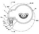
- the side surface 44a of the port member 44 and the side surface 47a of the protrusion 47 are both formed in a planar shape, and are joined to each other on a common virtual plane Ifp. Since the virtual plane Ifp of the present embodiment is set along the axial direction of the filter case 43, the port member 44 is joined in a posture that projects from the protrusion 47 in a direction orthogonal to the axial direction.
- the port member 44 of the present embodiment protrudes in the tangential direction of the circular contour with respect to the outer peripheral surface 461a of the outer cylinder portion 461 that is curved in a cylindrical shape as a “curved surface”.
- the diameter of the circumscribed circle C in FIG. 3 that contacts the outer periphery of the filter case 43 including the outer periphery of the protrusion 47 that is the outer periphery of the specific portion S and also contacts the outer periphery of the port member 44 is The overhang amount of the port member 44 is set so as to be as small as possible.
- the port member 44 integrally includes a discharge port 440, a jet port 441, a relief port 442, and a relief valve 443 outside the filter case 43.
- the discharge port 440 is formed in an L-shaped space at the top of the port member 44 in the vertical direction. As shown in FIG. 2, the discharge port 440 communicates with a discharge passage 472 that opens to the side surface 47a. At the same time, the discharge port 440 communicates with the flexible tube 12a (see FIG. 1) by directing the most downstream end upward on the side opposite to the communication portion of the discharge passage 472. With these communication modes, the discharge port 440 communicates with the fuel passage 470 in the filter case 43 via the discharge passage 472, and on the internal combustion engine 3 side outside the filter case 43 via the flexible tube 12 a and the fuel supply pipe 12. Through.
- the discharge port 440 functioning as one of “a plurality of fuel ports” allows the fuel flowing from the fuel passage 470 to the discharge passage 472 to flow to the internal combustion engine 3 side. Dispense toward.
- the jet port 441 is formed in an inverted L-shaped space at the lower end portion of the port member 44 located below the discharge port 440.
- the jet port 441 communicates with the branch passage 474 that opens to the side surface 47a, and communicates with the jet pump 45 on the side opposite to the communication location.
- the jet port 441 communicates with the fuel passage 470 in the filter case 43 via the branch passage 474 and directly communicates with the jet pump 45 outside the filter case 43.
- the jet port 441 functioning as one of “a plurality of fuel ports” allows the discharged fuel from the fuel passage 470 through the internal residual pressure holding valve 475 to be discharged.
- the guide action toward the jet pump 45 is exhibited.
- the relief port 442 is formed in a stepped cylindrical hole shape at an intermediate portion located between the ports 440 and 441 in the vertical direction of the port member 44.
- the relief port 442 communicates with the relief passage 476 that opens to the side surface 47a, and communicates with the relief valve 443 on the side opposite to the communicating portion.
- the relief port 442 communicates with the fuel passage 470 in the filter case 43 via the relief passage 476 and directly communicates with the relief valve 443 outside the filter case 43.
- the relief port 442 functioning as one of the “plurality of fuel ports” by passing through the inside and outside of the filter case 43 in this way allows the fuel to be separated from the flow toward the internal combustion engine 3 in the fuel passage 470.
- the guide action toward the relief valve 443 is exhibited.
- the relief valve 443 is provided in the relief port 442 and communicates with the fuel passage 470 via the relief passage 476. Further, the relief valve 443 communicates with the internal space 26 of the sub tank 20 through the most downstream end 442 a of the relief port 442, so that the guide fuel in the relief passage 476 can be discharged to the space 26.
- the relief valve 443 is a spring biased check valve in the present embodiment.
- the relief valve 443 opens and closes the fuel passage 470 that communicates with the relief port 442.
- the relief valve 443 is closed while the normal state of the fuel supply path from the fuel passage 470 to the internal combustion engine 3 is maintained and the pressure of the relief port 442 becomes less than the relief pressure regardless of the operation and stop of the fuel pump 42. I speak.
- the fuel pressure-regulated by the operation of the fuel pump 42 when the valve is closed is discharged through the discharge passage 472 in the filter case 43 and the discharge port 440 outside the case 43, thereby supplying fuel to the internal combustion engine 3 side. Become.
- the relief valve 443 is Open the valve.
- the guide fuel to the relief valve 443 is discharged into the internal space 26 of the sub tank 20 and is thus released until the pressure of the fuel supplied to the internal combustion engine 3 reaches the relief pressure. That is, the relief function by the opened relief valve 443 is exerted on the fuel supplied to the internal combustion engine 3 side.
- the relief pressure by the relief function of the relief valve 443 is set to be 650 kPa, for example.
- the jet pump 45 is formed in a hollow shape with resin and is disposed below the port member 44 in the sub tank 20.
- the jet pump 45 is placed on the bottom 20a of the sub tank 20 particularly on the concave bottom 20b. With such a mounting form, the jet pump 45 and the port member 44 overlap the inflow port 24 in the axial direction of the filter case 43 on the bottom 20a.
- the jet pump 45 integrally includes a pressurizing unit 450, a nozzle unit 451, a suction unit 452, and a diffuser unit 453.
- the pressurizing unit 450 has a pressurizing passage 454 formed in a stepped cylindrical hole extending along the axial direction of the filter case 43.
- the pressurizing passage 454 is located below the port member 44 and communicates with the jet port 441. Under such a communication form, the pressurized fuel discharged from the fuel passage 470 in the filter case 43 through the branch passage 474 in the case 43 passes through the jet port 441 outside the case 43 to the pressurized passage 454. Guided.
- the nozzle portion 451 forms a nozzle passage 455 in a cylindrical hole shape extending in a direction orthogonal to the axial direction of the filter case 43.
- the nozzle passage 455 is located below the pressurizing unit 450 and communicates with the pressurizing passage 454. Further, the nozzle passage 455 is narrower in the passage cross-sectional area than the pressurizing passage 454. Under these communication and throttle configurations, the pressurized fuel guided to the pressurized passage 454 flows into the nozzle passage 455.
- the suction portion 452 forms a suction passage 456 in a flat space extending in a direction orthogonal to the axial direction of the filter case 43.
- the suction passage 456 is located below the pressurizing part 450 and the nozzle part 451 and communicates with the inflow port 24. Under such a communication mode, the fuel that has flowed into the sub tank 20 through the inflow port 24 flows through the suction passage 456.
- the diffuser portion 453 forms a diffuser passage 457 in a cylindrical hole shape extending in a direction orthogonal to the axial direction of the filter case 43.
- the diffuser passage 457 is located below the pressurizing unit 450 and communicates with the nozzle passage 455 and communicates with the internal space 26 of the sub tank 20 on the side opposite to the communication portion. Further, the diffuser passage 457 has a passage sectional area larger than that of the nozzle passage 455. Under these communication and expansion modes, when the pressurized fuel that has flowed into the nozzle passage 455 is ejected into the diffuser passage 457 and a negative pressure is generated around the ejection flow, the fuel in the fuel tank 2 flows from the inlet 24.
- the air is sequentially sucked into the suction passage 456 and the diffuser passage 457.
- the fuel thus sucked is subjected to a diffuser action in the diffuser passage 457 and is pumped to be transferred to the internal space 26 including the periphery of the fuel pump 42.
- the diffuser passage 457 having a large-diameter circular cross section is eccentric upward with respect to the nozzle passage 455 having a small-diameter circular cross section.
- the most downstream end 457a communicating with the internal space 26 in the diffuser passage 457 of the present embodiment is spaced upward from the deepest bottom portion 20d surrounding the concave bottom portion 20b of the bottom portion 20a of the sub tank 20. .
- the external residual pressure holding valve 473 is provided at the junction boundary B between the bottomed case body 430 and the case cap 431. Thereby, the assembly of the case cap 431 to the case main body 430 and the assembly of the external residual pressure holding valve 473 to the case main body 430 can be performed at a common location. Therefore, it is possible to improve the productivity of the apparatus 1 that exhibits the function of holding the residual pressure of the fuel supplied to the internal combustion engine 3 side by the external residual pressure holding valve 473.
- the valve housing 477 that accommodates the valve element 478 in the external residual pressure holding valve 473 is joined to the elements 430 and 431 at the joining boundary B between the case main body 430 and the case cap 431. It is done. Therefore, by performing the operation of joining the valve housing 477 to the elements 430 and 431, the assembly of the case cap 431 to the case body 430 and the assembly of the external residual pressure holding valve 473 to the case body 430 are performed at a common location. It can be realized at the same time. Moreover, after such joining work, the valve element 478 is seated on the valve seat 477as of the valve housing 477 as the fuel pump 42 stops, so that the pressure of the fuel supplied to the internal combustion engine 3 can be reliably maintained. From these things, it becomes possible to raise the productivity of the apparatus 1 with the reliability of a residual pressure holding function.
- the joint of the valve housing 477 with the elements 430 and 431 is performed on the common virtual plane Icv, so that not only the joining work is facilitated, but also poor joining is hardly caused. Become. According to this, it is possible to increase the yield of the apparatus 1 as well as the productivity.
- valve housing 477 press-fitted into the case main body 430 is used for joining with the elements 430 and 431, so that not only the joining work is facilitated, but also the positional deviation of the valve housing 477 is poor. Can be suppressed. According to this, it is possible to increase the yield of the apparatus 1 as well as the productivity.
- valve housing 477 positioned by being sandwiched between the case main body 430 and the case cap 431 can be joined to the elements 430 and 431. According to this, not only the joining work is facilitated, but also misalignment of the valve housing 477 can be suppressed, so that it is possible to increase the yield as well as the productivity of the device 1.
- the fuel passage 470 communicating with the internal combustion engine 3 via the external residual pressure holding valve 473 is folded in the axial direction of the filter case 43.
- the fuel passage 470 has a valve at the upstream side and the downstream side formed in the case body 430 rather than the folded portion 470a formed in the case cap 431, that is, at the upstream straight portion 470b and the downstream straight portion 470c. It penetrates the housing 477. According to such a penetration form, the fuel passage 470 can be reliably secured in the filter case 43 including the elements 430 and 431 with the valve housing 477 interposed therebetween.
- the valve element 478 is separated from the valve seat 477as at the upstream straight portion 470b penetrating the valve housing 477, so that the residual pressure holding function by the external residual pressure holding valve 473 is reliably exhibited. it can. According to these, the arrangement range of the fuel passage 470 and the external residual pressure holding valve 473 can be set small in the radial direction of the filter case 43, and the apparatus 1 that exhibits the residual pressure holding function can be downsized. . (Second embodiment) As shown in FIG. 5, the second embodiment of the present disclosure is a modification of the first embodiment.
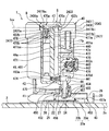
- a press-fit recess 2433 having a flat space shape is formed around the opening of the folded portion 470a in the lower portion of the case cap 2431.
- the joint plate 2477b of the valve housing 2477 is press-fitted into the press-fit recess 2433.
- the lower surface portion 2477bl and the upper surface portion 2477bu of the joining plate 2477b are both formed in a planar shape. With this shape, the lower surface portion 2477bl is joined to the inner peripheral edge portion of the press-fit recess 2433 and the upper surface portion 2430a of the case main body 2430 of the lower surface portion 2431a of the case cap 2431 by welding on the common virtual plane Icv. Yes.
- the joining plate 2477b sandwiched between the case body 2430 and the case cap 2431 and entered into the cap 2431 has a part of the upstream straight part 470b and a part of the downstream straight part 470c. Penetrates in the vertical direction.
- the steps as shown in FIG. 6 are sequentially executed.
- the joining plate 2477 b is press-fitted into the case cap 2431.
- the joint body 2477b and the case cap 2431 are overlapped on the common virtual plane Icv and welded to the case body 2430 while the housing body 477a is fitted.
- 2430, 2477b, and 2431 are joined.
- the external residual pressure holding valve 2473 is provided at the junction boundary B between the case body 2430 and the case cap 2431 in the filter case 2043 as shown in FIG.
- the valve housing 2477 press-fitted into the case cap 2431 is used for joining with the elements 2430 and 2431, so that not only the joining work is facilitated, but also the valve housing 2477 Misalignment can be suppressed. According to this, it is possible to increase the yield of the apparatus 1 as well as the productivity. In other respects, the same effects as the first embodiment can be exhibited by the configuration of the second embodiment.
- the third embodiment of the present disclosure is a modification of the first embodiment.
- the press-fitting recess 3433 of the third embodiment is formed in a flat space only around the upstream opening 432b corresponding to the upstream straight portion 470b in the upper part of the case body 3430.
- valve housing 3477 of the third embodiment is formed by integrally forming a joining flange 3477b instead of the joining plate 477b together with the housing main body 477a using a resin.
- the joint flange 3477b provided continuously with the upper portion of the housing main body 477a is formed in an annular collar shape along the outer periphery of the main body 477a.
- the joining flange 3477b is press-fitted into the press-fit recess 3433.
- the upper surface portion 3477bu and the lower surface portion 3477bl of the joining flange 3477b are both formed in a planar shape.
- the upper surface portion 3477bu is joined to the inner peripheral edge portion of the press-fit recess 3433 in the upper surface portion 3430a of the case body 3430 and the lower surface portion 431a of the case cap 431 by welding on the common virtual plane Icv. Yes.
- a part of the upstream straight portion 470b penetrates in the vertical direction in the joining flange 3477b sandwiched between the case main body 3430 and the case cap 431.
- the steps shown in FIG. 8 are sequentially performed.
- the housing main body 477a is fitted into the case main body 3430 and the joining flange 3477b is press-fitted.
- the case cap 431 is overlapped and welded to the case main body 3430 and the joint flange 3477b on the common virtual plane Icv, thereby joining the elements 431, 3430, and 3477b.
- the external residual pressure holding valve 3473 is provided at the junction boundary B between the case body 3430 and the case cap 431 in the filter case 3043.
- the fuel passage 470 passes through the valve housing 3477 in the upstream straight portion 470 b formed in the case main body 3430. According to such a penetration form, the fuel passage 470 can be reliably secured in the filter case 3043 including the elements 3430 and 431 with the valve housing 3477 interposed therebetween.
- the valve element 478 is separated from the valve seat 477as at the upstream straight portion 470b penetrating the valve housing 3477, so that the residual pressure holding function by the external residual pressure holding valve 3473 is provided. Can be demonstrated reliably.
- the fourth embodiment of the present disclosure is a modification of the third embodiment.
- the downstream straight portion 4470c of the fourth embodiment extends the most downstream end 4470d at the protrusion 4047 to a position lower than the branch passage 4474.
- the branch passage 4474 is provided so as to intersect with the downstream straight portion 4470c, particularly in the present embodiment, substantially orthogonal.
- the passage wall 4474a of the branch passage 4474 secures a passage cross-sectional area toward the most downstream end 4470d side between the passage wall 4470cw of the downstream straight portion 4470c entering by the intersection. .
- the relief passage 4476 of the fourth embodiment is formed in a stepped cylindrical hole shape at the lower end portion of the protrusion 4047 that extends downward from the branch passage 4474. Yes.
- the relief passage 4476 further extends in the axial direction of the filter case 4043 from the most downstream end 4470d of the fuel passage 4470.
- the port member 4044 of the fourth embodiment is joined to the protrusion 4047 of the filter case 4043 to form the discharge port 440 and the jet port 441, but the relief port 442 is formed.
- the relief valve 4443 of the fourth embodiment is provided in the relief passage 4476 in the filter case 4043 and communicates with the fuel passage 4470 to open and close the passage 4470. It functions as one of "multiple open / close valves". Further, the relief valve 4443 communicates with the internal space 26 of the sub tank 20 through the most downstream end 4476a of the relief passage 4476.
- the relief valve 4443 can discharge the guide fuel into the internal space 26 by guiding the fuel separated from the flow toward the internal combustion engine 3 in the filter case 4043 from the relief passage 4476. It has become.
- the operation of the relief valve 4443 is substantially the same as that of the relief valve 443 described in the first embodiment.
- the fifth embodiment of the present disclosure is a modification of the fourth embodiment.
- the port member 5044 of the fifth embodiment is inclined from the tangential direction of the circular outline to the same surface 461a side with respect to the cylindrical outer peripheral surface 461a of the accommodating portion 46 of the filter case 4043, and protrudes from the protrusion 4047. ing.
- the port member 5044 forms the discharge port 5440 and the jet port 5441 along the outer peripheral surface 461a by this projecting form.
- the sixth embodiment of the present disclosure is a modification of the first embodiment.
- the pressure of the pressurized fuel discharged from the fuel pump 7042 of the sixth embodiment is variably adjusted, for example, within a range of 300 kPa to 600 kPa.
- a relay passage 7465 communicating with the housing chamber 463 is formed in a substantially rectangular hole shape that is inclined with respect to the axial direction of the filter case 43 along the vertical direction.
- the relay passage 7465 communicates with the fuel outlet 463 a that opens below the fuel filter 464 in the accommodation chamber 463.
- the relay passage 7465 is inclined more obliquely upward as it is separated from the fuel outlet 463a in the radially outward direction.
- the inclined relay passage 7465 guides the fuel that is filtered by the fuel filter 464 and led out from the fuel outlet 463a obliquely upward.
- a fuel passage 7470 of the sixth embodiment forms a communication port 7470e so as to open at an intermediate portion in the vertical direction of the upstream straight portion 7470b.
- the upstream straight portion 7470b is disposed on the downstream side of the fuel filter 464 by allowing the communication port 7470e to communicate with the storage chamber 463 through the relay passage 7465. With this arrangement, the pressurized fuel guided through the relay passage 7465 is led out from the communication port 7470e to the upstream straight portion 7470b.
- the upstream straight portion 7470b forms an external passage portion 7470f where the communication port 7470e opens and an internal passage portion 7470g which communicates with the communication port 7470e via the external passage portion 7470f.
- the external passage portion 7470f and the internal passage portion 7470g are housed in the projecting portion 7047 together with the elements 471, 472, 7473, 7474, 7475, and 476 of the specific portion S.
- the external passage portion 7470f causes the fuel led out from the communication port 7470e to flow to the external residual pressure holding valve 7473 side above the port 7470e.
- the fuel flow direction in the relay passage 7465 is inclined with respect to the fuel flow direction in the external passage portion 7470f as shown in FIG.
- the cross-sectional area of the external passage portion 7470f is larger than the cross-sectional area of the relay passage 7465 that relays between the communication port 7470e and the storage chamber 463.
- the external passage portion 7470f having such an enlarged form guides the pressurized fuel from the communication port 7470e toward the downstream straight portion 470c in order to be discharged through the discharge passage 472.
- the fuel guided by the relay passage 7465 and led out from the communication port 7470e is returned to the internal residual pressure holding valve 7475 side through the external passage portion 7470f, and flows toward the internal passage portion 7470g.
- the fuel circulation direction in the relay passage 7465 is also inclined with respect to the fuel circulation direction in the internal passage portion 7470g.
- the passage sectional area of the inner passage portion 7470g is smaller than the passage sectional area of the relay passage 7465 and the passage sectional area of the outer passage portion 7470f. With such a reduced form, the fuel flow toward the internal residual pressure holding valve 7475 side in the internal passage portion 7470g is restricted more than in the external passage portion 7470f.
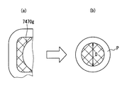
- the minimum cross-sectional area of the internal passage portion 7470g shown with cross-hatching in FIG. 18A is taken as the cross-sectional area of the cylindrical pipe P shown with cross-hatching in FIG. 18B. , Convert virtually.
- the passage diameter D of the cylindrical pipe P obtained from the converted passage cross-sectional area, and the length L of the internal passage portion 7470g that is the distance from the external passage portion 7470f to the internal residual pressure holding valve 7475 shown in FIG. Is set so as to satisfy the relational expression of L / D ⁇ 3.
- the reason why the passage diameter D and the length L are set so as to satisfy the relational expression L / D ⁇ 3 will be described in detail later.
- the internal residual pressure holding valve 7475 located on the downstream side of the internal passage portion 7470g is disposed to be spaced downward from the external residual pressure holding valve 7473 as shown in FIGS.
- a communication port 7470e is opened at a position R that is displaced from the internal residual pressure holding valve 7475 to the external residual pressure holding valve 7473 side, and more than the position deviation position R.
- An internal passage portion 7470g is opened downward.
- the opening of the internal passage portion 7470g is located in a separation portion Q of the external passage portion 7470f that is spaced radially outward from the relay passage 7465 with the internal residual pressure holding valve 7475 interposed therebetween. Is provided.
- the configuration of the fuel passage 7470 other than that described above conforms to the configuration of the fuel passage 470 described in the first embodiment.
- the external residual pressure holding valve 7473 which is a springless check valve as one of “a plurality of on-off valves” is more than the communication port 7470e in the upstream straight portion 470b.
- the external passage portion 7470 f is provided on the downstream side and on the upstream side of the discharge passage 472. That is, the external residual pressure holding valve 7473 is disposed in the middle of the fuel passage 7470 from the communication port 7470e toward the discharge passage 7472.
- the external residual pressure holding valve 7473 includes a valve stopper 7479 together with the valve housing 477 and the valve element 478 described in the first embodiment.
- the valve stopper 7479 is formed of a resin in a cylindrical shape, and is coaxially fixed in the housing main body 477a.
- the valve stopper 7479 supports the valve element 478 so as to be able to reciprocate.
- the valve stopper 7479 locks the valve element 478 at the time of valve opening separated from the valve seat 477as.
- the external residual pressure holding valve 7473 opens and closes the fuel passage 7470. Specifically, as the fuel pump 7042 is operated, the valve element 478 of the external residual pressure holding valve 7473 is opened while the pressurized fuel is led out from the communication port 7470e to the external passage portion 7470f. When the valve is opened, the pressurized fuel led out to the external passage portion 7470f moves toward the most downstream end 470d side of the discharge passage 472 and the downstream straight portion 470c while the valve element 478 is locked to the valve stopper 7479. Fluid. On the other hand, the valve element 478 is closed when the fuel pump 7042 stops and the fuel is stopped from being led out from the communication port 7470e.
- the closed external residual pressure holding valve 7473 provides a residual pressure holding function for the fuel supplied to the internal combustion engine 3 through the fuel passage 7470.
- the holding pressure by the residual pressure holding function of the external residual pressure holding valve 7473 is the pressure that was adjusted when the fuel pump 7042 was stopped.
- the configuration of the external residual pressure holding valve 7473 other than that described above conforms to the configuration of the external residual pressure holding valve 473 described in the first embodiment.
- the branch passage 7474 of the sixth embodiment is a spatial shape extending from the portion sandwiched between the relay passage 7465 and the internal passage portion 7470g at the radially spaced portion Q in the protrusion 7047 to the port member 44 side. Is formed.
- the branch passage 7474 branches from the lower end of the internal passage portion 7470g opposite to the external passage portion 7470f so as to be folded upward.
- the branch passage 7474 having such a branching shape does not intersect the downstream straight portion 470c.
- the branch passage 7474 opens to the side surface 47a of the projection 7047 and communicates with the jet port 441, thereby guiding the fuel discharged from the internal passage portion 7470g through the internal residual pressure holding valve 7475 to the jet pump 45. .
- the fuel thus guided flows into the nozzle passage 7455 whose passage cross-sectional area is narrower than that of the upstream internal passage portion 7470 g and the pressurization passage 454.
- the flow rate is reduced and ejected into the diffuser passage 457.
- the diffuser passage 457 having a large diameter circular cross section is aligned with the nozzle passage 7455 having a small circular cross section.
- an umbrella valve 7027 that opens the inlet 24 when a negative pressure from the jet pump 45 is applied. Is provided.
- an internal residual pressure holding valve 7475 which is a spring-biased check valve, is provided in the branch passage 7474 as another “a plurality of open / close valves”.
- the internal residual pressure holding valve 7475 has a valve housing 7475a, a valve element 7475b, and a valve spring 7475c.
- the valve housing 7475a is formed in a stepped cylindrical shape from a metal composite material, and is fitted into the protrusion 7047. A part of the branch passage 7474 passes through the valve housing 7475a.
- the valve housing 7475a forms a planar valve seat 7475as in the branch passage 7474.
- an annular plate-shaped flange portion 7475af is provided so as to overlap the lower portion of the relay passage 7465 and the lower portion of the internal passage portion 7470g, thereby positioning the internal residual pressure holding valve 7475 by the protrusion 7047 and the device. 1 is miniaturized.
- the valve element 7475b is formed in a cylindrical shape from a metal composite material, and is coaxially accommodated in the valve housing 7475a. With this accommodation form, the valve element 7475b can be separated from and seated on the valve seat 7475as by reciprocating movement. Therefore, the internal residual pressure holding valve 7475 opens in response to the valve element 7475b separating from the valve seat 7475as, and closes in response to the valve element 7475b seating on the valve seat 7475as.
- the valve spring 7475c is formed of a metal in a coil shape, and is coaxially locked in the valve housing 7475a.
- the valve spring 7475c biases the valve element 7475b toward the valve seat 7475as by a spring reaction force.
- the internal residual pressure holding valve 7475 opens and closes the fuel passage 7470 that communicates with the branch passage 7474.
- the valve element 7475 b of the internal residual pressure holding valve 7475 is connected to the valve spring 7475 c while the fuel of the set pressure or higher is led out from the communication port 7470 e to the passage portions 7470 f and 7470 g.
- the valve opens against the spring reaction force.
- the valve element 7475b is moved to the spring. Closes due to reaction force.
- the pressure of the fuel in the storage chamber 463 is also taken into account when the delivery valve 421 is closed. Is held at the set pressure of the internal residual pressure holding valve 7475. That is, the internal pressure maintaining valve 7475 which is closed provides a residual pressure maintaining function for the staying fuel in the storage chamber 463.
- the holding pressure by the residual pressure holding function of the internal residual pressure holding valve 7475 is set to be 250 kPa, for example.
- the valve element 7475b has a pressure pulsation generated by the fuel pumping from the fuel pump 7042 when the lift amount (separation amount) from the valve seat 7475as is small.
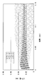
- the passage diameter D of the cylindrical pipe P converted from the passage cross-sectional area of the internal passage portion 7470g and the length L of the passage portion 7470g are L / D ⁇ 3. Is set so as to satisfy the relational expression. As a result of such setting, the vibration of the valve element 7475b due to pressure pulsation is attenuated to substantially zero level as time passes, as shown in FIG.
- the relief valve 7443 which is a spring biased check valve is provided in the relief port 442.
- the relief valve 7443 communicates with the fuel passage 7470 through a relief passage 476 that opens to the side surface 47 a of the projection 7047.
- the relief valve 7443 communicates with the internal space 26 of the sub tank 20 through the most downstream end 442a of the relief port 442. As a result, the guide fuel from the relief passage 476 to the relief port 442 can be discharged into the space 26.
- the relief valve 7443 includes a valve retainer 7443a, a valve element 7443b, and a valve spring 7443c.
- valve retainer 7443a is formed in a cylindrical shape from resin and is fitted into the port member 44.
- the valve retainer 7443a passes through the most downstream end 442a downstream of the stepped portion of the relief port 442 that forms the valve seat 7442s in a planar shape.
- the valve element 7443b is formed in a disc shape from a composite material of resin and rubber, and is accommodated coaxially in the relief port 442. With this accommodation form, the valve element 7443b can be separated from and seated on the valve seat 7442s by reciprocating movement. Accordingly, the relief valve 7443 is opened in response to the valve element 7443b being separated from the valve seat 7442s, and is closed in response to the valve element 7443b being seated on the valve seat 7442s.
- the valve spring 7443c is formed in a coil shape from metal.
- the valve spring 7443c is accommodated coaxially in the relief port 442, and is locked by the valve retainer 7443a.
- the valve spring 7443c urges the valve element 7443b toward the valve seat 7442s by a spring reaction force.
- the relief valve 7443 opens and closes the fuel passage 7470 that communicates with the relief port 442 via the relief passage 476. Specifically, while the normal state of the fuel supply path from the fuel passage 7470 to the internal combustion engine 3 is maintained and the pressure of the relief port 442 becomes less than the relief pressure regardless of the operation and stop of the fuel pump 7042, The valve element 7443b of the relief valve 7443 is closed by the spring reaction force of the valve spring 7443c. The fuel pressure-adjusted by the operation of the fuel pump 7042 when the valve is closed is discharged through the discharge passage 472 in the filter case 43 and the discharge port 440 outside the case 43, thereby supplying fuel to the internal combustion engine 3 side. Become.
- the valve element 7443b is The valve opens against the spring reaction force.
- the guide fuel to the relief valve 7443 is discharged into the internal space 26 of the sub tank 20 while the valve element 7443b is elastically supported by the valve spring 7443c. Therefore, the fuel is released until the pressure of the fuel supplied to the internal combustion engine 3 reaches the relief pressure. That is, the relief function by the opened relief valve 7443 is exerted on the fuel supplied to the internal combustion engine 3 side.
- the relief pressure by the relief function of the relief valve 7443 is set to be 650 kPa, for example.
- the external residual pressure holding valve 7473 is a springless type having a valve element 478 that is opened by the operation of the fuel pump 7042 and locked to the valve stopper 7479. For this reason, even if pressure pulsation occurs due to fuel pumping from the fuel pump 7042, the locked valve element 478 is unlikely to vibrate.
- the internal residual pressure holding valve 7475 is a spring-biased type having a valve element 7475b that opens against the spring reaction force when the fuel pump 7042 is operated.
- the communication port 7470e that communicates with the storage chamber 463 downstream of the fuel filter 464 is connected to the external residual pressure from the internal residual pressure holding valve 7475.
- An opening is made at a position R where the holding valve 7473 is displaced.
- the length L can be increased to satisfy the equation.
- the pressure pulsation generated by the fuel pumping from the fuel pump 7042 can be damped by the internal passage portion 7470g which is narrowed down to the spring biased valve 7475.
- the vibration of element 7475b can also be damped.
- the communication port 7470e relayed between the storage chamber 463 by the relay passage 7465 opens at the misalignment location R.
- the length L can be increased so as to satisfy the relational expression of L / D ⁇ 3 for the internal passage portion 7470g for restricting the fuel flow from the communication port 7470e to the valve 7475
- the length of the relay passage 7465 from 463 to the same port 7470e can also be increased.
- the pressure pulsation generated by the fuel pumping from the fuel pump 7042 can be attenuated by the long relay passage 7465 and the long internal passage portion 7470g until it goes to the spring biased valve 7475. . Therefore, the noise reduction effect can be enhanced.
- the communication port 7470e that opens to the external passage portion 7470f at the misalignment location R communicates with the internal passage portion 7470g via the passage portion 7470f.
- the fuel flow in the internal passage portion 7470g is narrower than that in the external passage portion 7470f, the flow rate of fuel flowing through the external passage portion 7470f for the discharge to the internal combustion engine 3 side is secured while the internal flow portion 7470g is secured. Noise can be reduced by attenuating the pressure pulsation at the passage portion 7470g.
- the internal passage portion 7470g opens in a separation portion Q between the relay passage 7465 and the valve 7475 in the external passage portion 7470f.
- the distance from the communication port 7470e to the location Q in the external passage portion 7470f can be increased along with the length of the relay passage 7465.
- the pressure pulsation generated by the fuel pumping from the fuel pump 7042 is long between the long relay passage 7465 and each of the locations R and Q where the distance is secured until the pressure pulsation is directed to the spring biased valve 7475. It can be attenuated by the narrowed internal passage portion 7470g. Therefore, the noise reduction effect can be enhanced.
- the fuel flow direction in the relay passage 7465 is inclined with respect to the fuel flow direction in the internal passage portion 7470g.
- the fuel flow from the relay passage 7465 toward the internal passage portion 7470g through the external passage portion 7470f is smoothly turned back, so that the fuel flow is separated from the inner wall surfaces forming the passage portions 7470f and 7470g. It becomes difficult to do. Therefore, it is possible to suppress the generation of a negative pressure due to such separation of the fuel flow and causing noise.
- the relief valve 7443 is supplied to the internal combustion engine 3 side by guiding the fuel separated from the flow toward the internal combustion engine 3 side in the fuel passage 7470 by the relief passage 476. Relieve fuel pressure. According to such a relief function, the durability of the internal combustion engine 3 can be guaranteed.
- a relief valve 7443 of a spring bias type in which the valve element 7443b is opened against the spring reaction force for pressure relief is provided with a relief from the downstream side of the external residual pressure holding valve 7473 in the fuel passage 7470. Fuel is guided through the passage 476.
- the valve 7443 can suppress the pressure pulsation from being amplified by the vibration of the valve element 7443b. As a result, it is possible to enhance the effect of reducing noise generated in the path from the fuel passage 7470 to the internal combustion engine 3.
- the jet pump 45 of the sixth embodiment causes the exhausted fuel that has passed through the valve 7475 to be further squeezed and ejected from the internal passage portion 7470g that has been squeezed long by satisfying the relational expression of L / D ⁇ 3.
- the fuel in the fuel tank 2 is transferred around the fuel pump 7042.
- the jet pump 45 the fuel whose pressure pulsation is attenuated can be ejected from the internal passage portion 7470g. For this reason, it is possible to stably exhibit the fuel transfer function and to suppress generation of noise that is annoying to humans due to intermittent fuel ejection.
- external residual pressure holding valves 473, 2473, 3743, 7473 may be provided at the joining boundary B set at a place other than the specific place S.
- a part other than the specific part S for example, a part of the filter case 43, 2043, 3043, 4043 in the circumferential direction as a non-contained part that does not contain the fuel filter 464 may be adopted.
- a spring for urging the valve element 478 toward the valve seat 477as is used as an external residual pressure holding valve 473, 2473. , 3743 may be provided. That is, spring-biased check valves may be employed for the external residual pressure holding valves 473, 2473, and 3743.
- valve housings 477, 2477, 3477, the case main bodies 430, 2430, 3430, and the case caps 431, 2431 are arranged in steps other than the virtual plane Icv. You may make it join.
- the valve housings 477, 2477, 3477 may not be joined to the case main bodies 430, 2430, 3430 or the case caps 431, 2431.
- valve housings 477 and 3477 may be press-fitted into the case cap 431 according to the second embodiment. Further, as a sixth modified example related to the first to sixth embodiments, the valve housings 477, 2477, 3477 are inserted into the case main bodies 430, 2430, 3430 or the case caps 431, 2431, and the press-fitting allowance is substantially zero. Or it is good also as a loose insertion state which opened the clearance gap.
- the fuel passages 470, 4470, 7470 may be formed in a shape that is not folded back in the axial direction.
- both the upstream straight portion 470b and the downstream straight portion 470c may be formed through the valve housing 3477 in accordance with the first embodiment.
- valve housings 477, 2477, 3477 are not sandwiched between the case main bodies 430, 2430, 3430 and the case caps 431, 2431. Also good.
- FIG. 13 which shows the modification 9 of 3rd embodiment, the joining flange 3477b is not connected with the housing main body 477a, and the press-fit recessed part 3433 is not formed in the case main body 3430.
- the valve housing 3477 is not press-fitted into the case main body 3430 or the case cap 431.
- FIG. 13 which shows the modification 9 of 3rd embodiment
- the fuel outlet 463a of the storage chamber 463 may be substantially coincident with the communication port 7470e without providing the relay passage 7465 in the filter case 43.
- the fuel flow direction in the relay passage 7465 may be set substantially orthogonal to or substantially parallel to the fuel flow direction in the internal passage portion 7470g. .
- an internal residual pressure holding valve 7475 is provided at a separation point Q separated from the relay passage 7465 with the internal passage portion 7470g interposed therebetween, and the separation portion Q of the external passage portion 7470f.
- the internal passage portion 7470g may be opened at a location closer to the relay passage 7465.
- the communication port 7470e is opened to the internal passage portion 7470g at the misalignment point R, so that the external passage portion 7470f is connected to the communication port 7470e via the internal passage portion 7470g. You may communicate with.
- a non-accommodating portion that does not accommodate the fuel filter 464 in the filter case 43 is provided in a part of the circumferential direction in a configuration in which the protrusion 7047 is not provided. May be set as the specific location S.
- at least one of the external residual pressure holding valve 7473 and the internal residual pressure holding valve 7475 may be provided in a part of the filter case 43 other than the protrusion 7047 at the specific location S. Good.
- the most downstream ends of the discharge ports 440 and 5440 may be directed in the lateral direction.
- electromagnetically driven relief valves 443, 4443, 7443 such as solenoid valves may be provided, or the relief valves 443, 4443, 7443 themselves may not be provided. Also good.
- fuel other than that discharged from the fuel passages 470, 4470, 7470 through the internal residual pressure holding valves 475, 7475 may be ejected by the jet pump 45.
- fuel other than that discharged from the fuel passages 470, 4470, 7470 through the internal residual pressure holding valves 475, 7475 may be ejected by the jet pump 45.
- exhaust fuel from the fuel pumps 42, 7042, return fuel from the internal combustion engine 3 side, and the like are employed as the fuel for ejection from the jet pump 45.
- the jet pump 45 may not be provided.
- port members 44, 4044, 5044 divided for each of the ports 440, 5440, 441, 5441, 442 may be adopted.
- a port member 44 divided corresponding to one and two of the ports 440, 441, and 442 may be employed.
Landscapes
- Engineering & Computer Science (AREA)
- Chemical & Material Sciences (AREA)
- Combustion & Propulsion (AREA)
- Mechanical Engineering (AREA)
- General Engineering & Computer Science (AREA)
- Fuel-Injection Apparatus (AREA)
- Cooling, Air Intake And Gas Exhaust, And Fuel Tank Arrangements In Propulsion Units (AREA)
Abstract
Description
(第一実施形態)
図1,2に示すように、本開示の第一実施形態による燃料供給装置1は、車両の燃料タンク2に搭載される。装置1は、燃料タンク2内の燃料を、内燃機関3の燃料噴射弁へ直接的に又は高圧ポンプ等を介して間接的に供給する。ここで、装置1の搭載される燃料タンク2は、樹脂又は金属により中空状に形成されることで、内燃機関3側へ供給する燃料を貯留する。また、装置1から燃料を供給する内燃機関3としては、ガソリンエンジンであってもよいし、ディーゼルエンジンであってもよい。尚、図1,2に示す装置1の上下方向は、水平面上における車両の上下方向と実質一致している。
以下、装置1の構成及び作動を説明する。
以上説明した第一実施形態の作用効果を、以下に説明する。
(第二実施形態)
図5に示すように本開示の第二実施形態は、第一実施形態の変形例である。第二実施形態において、ケースキャップ2431の下部のうち折り返し部470aの開口部周囲には、扁平形空間状の圧入凹部2433が形成される。この圧入凹部2433に対して、バルブハウジング2477の接合プレート2477bが圧入されている。ここで、接合プレート2477bの下面部2477blと上面部2477buとは、いずれも平面状に形成されている。かかる形状により下面部2477blは、ケースキャップ2431の下面部2431aのうち圧入凹部2433の内周縁部と、ケース本体2430の上面部2430aとに対して、共通仮想平面Icv上での溶着により接合されている。これらの圧入及び接合形態下、ケース本体2430及びケースキャップ2431間に挟持されて同キャップ2431内へと入り込んだ接合プレート2477bには、上流ストレート部470bの一部と下流ストレート部470cの一部とが上下方向に貫通している。
(第三実施形態)
図7に示すように本開示の第三実施形態は、第一実施形態の変形例である。第三実施形態の圧入凹部3433は、ケース本体3430の上部のうち上流ストレート部470bの対応位置となる上流開口部432bの周囲のみに、扁平形空間状に形成されている。
(第四実施形態)
図9,10に示すように本開示の第四実施形態は、第三実施形態の変形例である。第四実施形態の下流ストレート部4470cは、突部4047において最下流端4470dを、分岐通路4474よりも下方にまで延長させている。かかる延長形態により分岐通路4474は、下流ストレート部4470cと交差、特に本実施形態では実質直交して設けられている。ここで図10に示すように、分岐通路4474の通路壁4474aは、交差により入り込んだ下流ストレート部4470cの通路壁4470cwとの間に、最下流端4470d側への通路断面積を確保している。
(第五実施形態)
図12に示すように本開示の第五実施形態は、第四実施形態の変形例である。第五実施形態のポート部材5044は、フィルタケース4043の収容部46のうち円筒面状の外周面461aに対して、その円形輪郭の接線方向から同面461a側に傾いて、突部4047から張り出している。かかる張り出し形態によりポート部材5044は、吐出ポート5440とジェットポート5441とを、外周面461aに沿って形成している。
(第六実施形態)
図14に示すように本開示の第六実施形態は、第一実施形態の変形例である。第六実施形態の燃料ポンプ7042から吐出される加圧燃料の圧力は、例えば300kPa~600kPaの範囲内で可変調整される。
(他の実施形態)
以上、本開示の複数の実施形態について説明したが、本開示は、それらの実施形態に限定して解釈されるものではなく、本開示の要旨を逸脱しない範囲内において種々の実施形態及び組み合わせに適用することができる。
Claims (13)
- 燃料ポンプ(42,7042)と、燃料フィルタ(464)を収容するフィルタケース(43,2043,3043,4043)とを、備え、前記燃料ポンプにより燃料タンク(2)内から圧送された燃料を、前記燃料フィルタにより濾過して前記フィルタケース内から内燃機関(3)側へ供給する燃料供給装置であって、
前記フィルタケースは、
前記燃料フィルタの収容室(463)を形成する有底状のケース本体(430,2430,3430)と、
前記ケース本体に接合されることより、前記ケース本体の開口部(432a,432b,432c)を覆蓋するケースキャップ(431,2431)と、
前記ケース本体と前記ケースキャップとの接合境界(B)に設けられ、前記フィルタケース内から前記内燃機関側へ供給された燃料の圧力を前記燃料ポンプの停止に伴い保持する残圧保持バルブ(473,2473,3743,7473)とを、有する燃料供給装置。 - 前記残圧保持バルブは、
前記ケース本体及び前記ケースキャップと接合され、弁座(477as)を形成するバルブハウジング(477,2477,3477)と、
前記バルブハウジング内に前記弁座に対して離着座可能に収容され、前記フィルタケース内から前記内燃機関側へ供給された燃料の圧力を、前記弁座に対する着座により保持するバルブエレメント(478)とを、組み合わせてなる請求項1に記載の燃料供給装置。 - 前記バルブハウジングは、前記ケース本体及び前記ケースキャップと共通の仮想平面上(Icv)にて接合される請求項2に記載の燃料供給装置。
- 前記バルブハウジングは、前記ケース本体又は前記ケースキャップに圧入される請求項2又は3に記載の燃料供給装置。
- 前記バルブハウジングは、前記ケース本体及び前記ケースキャップの間に挟持される請求項2~4のいずれか一項に記載の燃料供給装置。
- 前記フィルタケースは、軸方向にて折り返されることにより、前記残圧保持バルブを経由して前記内燃機関側に通じる燃料通路(470,4470,7470)を、有し、
前記燃料通路は、前記ケースキャップに形成される折り返し部(470a)よりも、前記ケース本体に形成される上流側箇所(470b,7470b)及び下流側箇所(470c,4470c)の少なくとも一方にて、前記バルブハウジングを貫通し、
前記バルブハウジングを貫通する前記上流側箇所又は前記下流側箇所にて、前記バルブエレメントが前記弁座に対して離着座する請求項5に記載の燃料供給装置。 - 前記残圧保持バルブは、前記内燃機関側へ供給された燃料の圧力を前記燃料ポンプ(7042)の停止に伴い保持するスプリングレス式の外部残圧保持バルブ(7473)として、前記燃料ポンプの作動に伴い開弁してバルブストッパ(7479)に係止されるバルブエレメント(478)を有した外部残圧保持バルブであり、
前記燃料フィルタよりも下流側にて前記収容室と連通する連通口(7470e)を有し、前記連通口から前記内燃機関側へ向かって吐出させる燃料を流通させる燃料通路(7470)が、前記フィルタケース(43)に設けられると共に、
前記収容室における燃料の圧力を前記燃料ポンプの停止に伴い保持するスプリング付勢式の内部残圧保持バルブ(7475)として、前記燃料ポンプの作動に伴いスプリング反力に抗して開弁するバルブエレメント(7475b)を有した内部残圧保持バルブが、前記フィルタケースに設けられ、
前記連通口は、前記燃料通路のうち前記内部残圧保持バルブから前記外部残圧保持バルブ側へ位置ずれした位置ずれ箇所(R)に開口し、
前記内燃機関側へ向かって吐出させるための燃料を前記連通口から前記外部残圧保持バルブ側へ向かって流通させる外部用通路部(7470f)と、前記連通口から前記内部残圧保持バルブ側へ向かって流通させる燃料の流れを前記外部用通路部よりも絞る内部用通路部(7470g)とは、前記燃料通路に形成され、
前記内部用通路部の通路断面積を円筒管(P)の通路断面積として変換した場合に、当該円筒管の通路直径Dと、前記内部用通路部の長さLとは、L/D≧3の関係式を満たす請求項1~6のいずれか一項に記載の燃料供給装置。 - 前記燃料通路を通して前記内燃機関側へ供給された燃料の圧力を逃がすスプリング付勢式のリリーフバルブ(7443)として、当該圧力逃がしのためにスプリング反力に抗して開弁するバルブエレメント(7443b)を有したリリーフバルブを、備え、
前記フィルタケースは、前記燃料通路のうち前記外部残圧保持バルブよりも下流側にて前記内燃機関側へ向かう流れとは分流された燃料を、前記リリーフバルブへ案内するリリーフ通路(476)を、有する請求項7に記載の燃料供給装置。 - 前記フィルタケースは、前記収容室及び前記連通口の間を中継する中継通路(7465)を、有する請求項7又は8に記載の燃料供給装置。
- 前記連通口は、前記位置ずれ箇所にて前記外部用通路部に開口し、
前記内部用通路部は、前記外部用通路部のうち前記中継通路から前記内部残圧保持バルブを挟んで離間した離間箇所(Q)に開口することにより、前記外部用通路部を介して前記連通口と連通する請求項9に記載の燃料供給装置。 - 前記中継通路における燃料の流通方向が前記内部用通路部における燃料の流通方向に対して傾斜することにより、前記中継通路からの燃料流れは、前記外部用通路部を通して折り返されて前記内部用通路部へ向かう請求項10に記載の燃料供給装置。
- 前記連通口は、前記位置ずれ箇所にて前記外部用通路部に開口することにより、前記外部用通路部を介して前記内部用通路部と連通する請求項7~11のいずれか一項に記載の燃料供給装置。
- 前記内部用通路部から前記内部残圧保持バルブを通して排出される燃料を絞って噴出させることにより、前記燃料タンク内の燃料を前記燃料ポンプの周囲へ移送するジェットポンプ(45)を、備える請求項7~12のいずれか一項に記載の燃料供給装置。
Priority Applications (4)
| Application Number | Priority Date | Filing Date | Title |
|---|---|---|---|
| DE112014005072.5T DE112014005072T5 (de) | 2013-11-05 | 2014-11-03 | Kraftstoffzufuhrvorrichtung |
| US15/031,094 US10024282B2 (en) | 2013-11-05 | 2014-11-03 | Fuel supply device |
| KR1020167012908A KR101869837B1 (ko) | 2013-11-05 | 2014-11-03 | 연료 공급 장치 |
| CN201480060584.XA CN105705764B (zh) | 2013-11-05 | 2014-11-03 | 燃料供给装置 |
Applications Claiming Priority (4)
| Application Number | Priority Date | Filing Date | Title |
|---|---|---|---|
| JP2013-229597 | 2013-11-05 | ||
| JP2013229597 | 2013-11-05 | ||
| JP2014175195A JP6248868B2 (ja) | 2013-11-05 | 2014-08-29 | 燃料供給装置 |
| JP2014-175195 | 2014-08-29 |
Publications (1)
| Publication Number | Publication Date |
|---|---|
| WO2015068375A1 true WO2015068375A1 (ja) | 2015-05-14 |
Family
ID=53041170
Family Applications (1)
| Application Number | Title | Priority Date | Filing Date |
|---|---|---|---|
| PCT/JP2014/005536 Ceased WO2015068375A1 (ja) | 2013-11-05 | 2014-11-03 | 燃料供給装置 |
Country Status (6)
| Country | Link |
|---|---|
| US (1) | US10024282B2 (ja) |
| JP (1) | JP6248868B2 (ja) |
| KR (1) | KR101869837B1 (ja) |
| CN (1) | CN105705764B (ja) |
| DE (1) | DE112014005072T5 (ja) |
| WO (1) | WO2015068375A1 (ja) |
Cited By (1)
| Publication number | Priority date | Publication date | Assignee | Title |
|---|---|---|---|---|
| US9915234B2 (en) | 2014-02-07 | 2018-03-13 | Kyosan Denki Co., Ltd. | Valve structure and fuel supply device |
Families Citing this family (8)
| Publication number | Priority date | Publication date | Assignee | Title |
|---|---|---|---|---|
| JP5571366B2 (ja) * | 2009-12-04 | 2014-08-13 | 愛三工業株式会社 | フィルタ装置 |
| JP6354463B2 (ja) * | 2013-11-05 | 2018-07-11 | 株式会社デンソー | 燃料供給装置 |
| JP6318987B2 (ja) * | 2013-11-05 | 2018-05-09 | 株式会社デンソー | 燃料供給装置 |
| JP6327067B2 (ja) * | 2014-08-29 | 2018-05-23 | 株式会社デンソー | 燃料供給装置 |
| JP6380363B2 (ja) * | 2015-12-17 | 2018-08-29 | 株式会社デンソー | 燃料ポンプユニット |
| JP6380364B2 (ja) * | 2015-12-17 | 2018-08-29 | 株式会社デンソー | 燃料ポンプ及び燃料ポンプモジュール |
| JP6696356B2 (ja) * | 2016-08-26 | 2020-05-20 | 株式会社デンソー | フィルタモジュール、および、これを用いた燃料ポンプモジュール |
| US10596899B2 (en) * | 2017-11-22 | 2020-03-24 | Kenneth C. Koch | Fuel tank filter assembly and fuel system |
Citations (2)
| Publication number | Priority date | Publication date | Assignee | Title |
|---|---|---|---|---|
| JP2002155823A (ja) * | 2000-09-06 | 2002-05-31 | Mitsubishi Electric Corp | 燃料供給装置 |
| JP2012035776A (ja) * | 2010-08-09 | 2012-02-23 | Honda Motor Co Ltd | 車両用燃料供給装置 |
Family Cites Families (27)
| Publication number | Priority date | Publication date | Assignee | Title |
|---|---|---|---|---|
| JP3734281B2 (ja) * | 1993-09-10 | 2006-01-11 | 株式会社デンソー | インタンク式燃料ポンプ |
| DE4430852A1 (de) * | 1994-08-31 | 1995-04-27 | Knecht Filterwerke Gmbh | Druckregelventil für in die Brennräume eines Verbrennungsmotors einzuspritzenden Kraftstoff |
| JP2003155963A (ja) | 2001-11-20 | 2003-05-30 | Kyosan Denki Co Ltd | フューエルポンプモジュールにおける脈動減衰装置 |
| JP2003293875A (ja) * | 2002-04-03 | 2003-10-15 | Aisan Ind Co Ltd | リザーブ容器ユニット |
| JP4051564B2 (ja) | 2002-10-18 | 2008-02-27 | 株式会社デンソー | 燃料供給装置 |
| WO2005035969A1 (de) * | 2003-09-18 | 2005-04-21 | A. Kayser Automotive Systems Gmbh | Filterbaueinheit und ventil für ein kraftstoffversorgungssystem |
| JP2007239682A (ja) | 2006-03-10 | 2007-09-20 | Denso Corp | 燃料供給装置 |
| JP2007255378A (ja) | 2006-03-24 | 2007-10-04 | Denso Corp | 燃料供給装置 |
| US7757671B2 (en) * | 2006-09-29 | 2010-07-20 | Denso Corporation | Fuel feed apparatus |
| US7631634B2 (en) * | 2007-11-08 | 2009-12-15 | Denso International America, Inc. | Fuel delivery module for high fuel pressure for engines |
| JP5136919B2 (ja) * | 2010-04-08 | 2013-02-06 | 株式会社デンソー | 高圧ポンプ |
| JP2012097640A (ja) | 2010-11-01 | 2012-05-24 | Denso Corp | 燃料供給装置 |
| JP5880979B2 (ja) * | 2013-08-28 | 2016-03-09 | 株式会社デンソー | 燃料ポンプモジュール |
| JP5983564B2 (ja) * | 2013-08-28 | 2016-08-31 | 株式会社デンソー | 燃料ポンプモジュール |
| JP5880978B2 (ja) * | 2013-08-28 | 2016-03-09 | 株式会社デンソー | 燃料ポンプモジュール |
| JP5880977B2 (ja) * | 2013-08-28 | 2016-03-09 | 株式会社デンソー | 燃料ポンプモジュールの製造方法 |
| JP5880976B2 (ja) * | 2013-08-28 | 2016-03-09 | 株式会社デンソー | 燃料ポンプモジュール |
| JP6354463B2 (ja) * | 2013-11-05 | 2018-07-11 | 株式会社デンソー | 燃料供給装置 |
| JP6318987B2 (ja) * | 2013-11-05 | 2018-05-09 | 株式会社デンソー | 燃料供給装置 |
| JP6311537B2 (ja) * | 2013-11-05 | 2018-04-18 | 株式会社デンソー | 燃料供給装置 |
| JP2015148214A (ja) * | 2014-02-07 | 2015-08-20 | 京三電機株式会社 | バルブ構造体及び燃料供給装置 |
| JP6162078B2 (ja) * | 2014-06-17 | 2017-07-12 | 愛三工業株式会社 | 燃料供給装置 |
| JP6327067B2 (ja) * | 2014-08-29 | 2018-05-23 | 株式会社デンソー | 燃料供給装置 |
| JP6432217B2 (ja) * | 2014-08-29 | 2018-12-05 | 株式会社デンソー | 燃料供給装置 |
| JP6365180B2 (ja) * | 2014-09-25 | 2018-08-01 | 株式会社デンソー | リリーフバルブ及び燃料供給システム |
| JP6331980B2 (ja) * | 2014-11-06 | 2018-05-30 | 株式会社デンソー | 燃料供給装置 |
| US10056800B2 (en) * | 2015-07-30 | 2018-08-21 | Delphi Technologies Ip Limited | Fluid delivery module |
-
2014
- 2014-08-29 JP JP2014175195A patent/JP6248868B2/ja not_active Expired - Fee Related
- 2014-11-03 CN CN201480060584.XA patent/CN105705764B/zh not_active Expired - Fee Related
- 2014-11-03 US US15/031,094 patent/US10024282B2/en not_active Expired - Fee Related
- 2014-11-03 WO PCT/JP2014/005536 patent/WO2015068375A1/ja not_active Ceased
- 2014-11-03 KR KR1020167012908A patent/KR101869837B1/ko active Active
- 2014-11-03 DE DE112014005072.5T patent/DE112014005072T5/de not_active Withdrawn
Patent Citations (2)
| Publication number | Priority date | Publication date | Assignee | Title |
|---|---|---|---|---|
| JP2002155823A (ja) * | 2000-09-06 | 2002-05-31 | Mitsubishi Electric Corp | 燃料供給装置 |
| JP2012035776A (ja) * | 2010-08-09 | 2012-02-23 | Honda Motor Co Ltd | 車両用燃料供給装置 |
Cited By (1)
| Publication number | Priority date | Publication date | Assignee | Title |
|---|---|---|---|---|
| US9915234B2 (en) | 2014-02-07 | 2018-03-13 | Kyosan Denki Co., Ltd. | Valve structure and fuel supply device |
Also Published As
| Publication number | Publication date |
|---|---|
| US20160245246A1 (en) | 2016-08-25 |
| JP6248868B2 (ja) | 2017-12-20 |
| CN105705764A (zh) | 2016-06-22 |
| DE112014005072T5 (de) | 2016-08-25 |
| US10024282B2 (en) | 2018-07-17 |
| KR101869837B1 (ko) | 2018-06-21 |
| CN105705764B (zh) | 2018-07-17 |
| KR20160072204A (ko) | 2016-06-22 |
| JP2015110937A (ja) | 2015-06-18 |
Similar Documents
| Publication | Publication Date | Title |
|---|---|---|
| JP6248868B2 (ja) | 燃料供給装置 | |
| JP6318987B2 (ja) | 燃料供給装置 | |
| JP6311537B2 (ja) | 燃料供給装置 | |
| JP6354463B2 (ja) | 燃料供給装置 | |
| JP6327067B2 (ja) | 燃料供給装置 | |
| JP6331980B2 (ja) | 燃料供給装置 | |
| JP6432217B2 (ja) | 燃料供給装置 | |
| US9915234B2 (en) | Valve structure and fuel supply device | |
| JP6365180B2 (ja) | リリーフバルブ及び燃料供給システム | |
| WO2016088360A1 (ja) | 燃料供給装置における取付構造、燃料供給装置及びその製造方法 |
Legal Events
| Date | Code | Title | Description |
|---|---|---|---|
| 121 | Ep: the epo has been informed by wipo that ep was designated in this application |
Ref document number: 14860306 Country of ref document: EP Kind code of ref document: A1 |
|
| WWE | Wipo information: entry into national phase |
Ref document number: 15031094 Country of ref document: US |
|
| WWE | Wipo information: entry into national phase |
Ref document number: 1120140050725 Country of ref document: DE Ref document number: 112014005072 Country of ref document: DE |
|
| ENP | Entry into the national phase |
Ref document number: 20167012908 Country of ref document: KR Kind code of ref document: A |
|
| WWE | Wipo information: entry into national phase |
Ref document number: 1020167012908 Country of ref document: KR |
|
| 122 | Ep: pct application non-entry in european phase |
Ref document number: 14860306 Country of ref document: EP Kind code of ref document: A1 |