WO2015060163A1 - 液体滞留装置及びその液体滞留装置を備えるオイルセパレータ - Google Patents
液体滞留装置及びその液体滞留装置を備えるオイルセパレータ Download PDFInfo
- Publication number
- WO2015060163A1 WO2015060163A1 PCT/JP2014/077338 JP2014077338W WO2015060163A1 WO 2015060163 A1 WO2015060163 A1 WO 2015060163A1 JP 2014077338 W JP2014077338 W JP 2014077338W WO 2015060163 A1 WO2015060163 A1 WO 2015060163A1
- Authority
- WO
- WIPO (PCT)
- Prior art keywords
- drain tank
- oil separator
- filter
- flange
- closing member
- Prior art date
- Legal status (The legal status is an assumption and is not a legal conclusion. Google has not performed a legal analysis and makes no representation as to the accuracy of the status listed.)
- Ceased
Links
Images




Classifications
-
- F—MECHANICAL ENGINEERING; LIGHTING; HEATING; WEAPONS; BLASTING
- F02—COMBUSTION ENGINES; HOT-GAS OR COMBUSTION-PRODUCT ENGINE PLANTS
- F02M—SUPPLYING COMBUSTION ENGINES IN GENERAL WITH COMBUSTIBLE MIXTURES OR CONSTITUENTS THEREOF
- F02M21/00—Apparatus for supplying engines with non-liquid fuels, e.g. gaseous fuels stored in liquid form
- F02M21/02—Apparatus for supplying engines with non-liquid fuels, e.g. gaseous fuels stored in liquid form for gaseous fuels
- F02M21/0218—Details on the gaseous fuel supply system, e.g. tanks, valves, pipes, pumps, rails, injectors or mixers
- F02M21/0227—Means to treat or clean gaseous fuels or fuel systems, e.g. removal of tar, cracking, reforming or enriching
-
- F—MECHANICAL ENGINEERING; LIGHTING; HEATING; WEAPONS; BLASTING
- F02—COMBUSTION ENGINES; HOT-GAS OR COMBUSTION-PRODUCT ENGINE PLANTS
- F02D—CONTROLLING COMBUSTION ENGINES
- F02D19/00—Controlling engines characterised by their use of non-liquid fuels, pluralities of fuels, or non-fuel substances added to the combustible mixtures
- F02D19/02—Controlling engines characterised by their use of non-liquid fuels, pluralities of fuels, or non-fuel substances added to the combustible mixtures peculiar to engines working with gaseous fuels
- F02D19/026—Measuring or estimating parameters related to the fuel supply system
-
- F—MECHANICAL ENGINEERING; LIGHTING; HEATING; WEAPONS; BLASTING
- F02—COMBUSTION ENGINES; HOT-GAS OR COMBUSTION-PRODUCT ENGINE PLANTS
- F02M—SUPPLYING COMBUSTION ENGINES IN GENERAL WITH COMBUSTIBLE MIXTURES OR CONSTITUENTS THEREOF
- F02M21/00—Apparatus for supplying engines with non-liquid fuels, e.g. gaseous fuels stored in liquid form
- F02M21/02—Apparatus for supplying engines with non-liquid fuels, e.g. gaseous fuels stored in liquid form for gaseous fuels
- F02M21/0203—Apparatus for supplying engines with non-liquid fuels, e.g. gaseous fuels stored in liquid form for gaseous fuels characterised by the type of gaseous fuel
- F02M21/0215—Mixtures of gaseous fuels; Natural gas; Biogas; Mine gas; Landfill gas
-
- F—MECHANICAL ENGINEERING; LIGHTING; HEATING; WEAPONS; BLASTING
- F02—COMBUSTION ENGINES; HOT-GAS OR COMBUSTION-PRODUCT ENGINE PLANTS
- F02M—SUPPLYING COMBUSTION ENGINES IN GENERAL WITH COMBUSTIBLE MIXTURES OR CONSTITUENTS THEREOF
- F02M21/00—Apparatus for supplying engines with non-liquid fuels, e.g. gaseous fuels stored in liquid form
- F02M21/02—Apparatus for supplying engines with non-liquid fuels, e.g. gaseous fuels stored in liquid form for gaseous fuels
- F02M21/0218—Details on the gaseous fuel supply system, e.g. tanks, valves, pipes, pumps, rails, injectors or mixers
- F02M21/023—Valves; Pressure or flow regulators in the fuel supply or return system
- F02M21/0239—Pressure or flow regulators therefor
-
- Y—GENERAL TAGGING OF NEW TECHNOLOGICAL DEVELOPMENTS; GENERAL TAGGING OF CROSS-SECTIONAL TECHNOLOGIES SPANNING OVER SEVERAL SECTIONS OF THE IPC; TECHNICAL SUBJECTS COVERED BY FORMER USPC CROSS-REFERENCE ART COLLECTIONS [XRACs] AND DIGESTS
- Y02—TECHNOLOGIES OR APPLICATIONS FOR MITIGATION OR ADAPTATION AGAINST CLIMATE CHANGE
- Y02T—CLIMATE CHANGE MITIGATION TECHNOLOGIES RELATED TO TRANSPORTATION
- Y02T10/00—Road transport of goods or passengers
- Y02T10/10—Internal combustion engine [ICE] based vehicles
- Y02T10/30—Use of alternative fuels, e.g. biofuels
Definitions
- the present invention relates to a liquid retention device including a drain tank for storing a liquid such as oil separated from gaseous fuel, and an oil separator including the liquid retention device.
- An oil separator that separates liquid such as oil from gaseous fuel is provided in a fuel supply device for supplying gaseous fuel to an internal combustion engine (see, for example, Patent Document 1).
- a filter element for separating the liquid from the gaseous fuel is provided in the upper region in the drain tank of the oil separator. The liquid separated from the gaseous fuel by the filter element accumulates in the drain tank.
- vibration and acceleration are generated as the vehicle travels, and these vibration and acceleration are transmitted to the oil separator.
- the liquid surface may shake in the drain tank, so that the liquid may be scattered or the liquid surface may wave.
- the sensor may erroneously output a detection signal due to the liquid droplets adhering to the sensor.
- An object of the present invention is to provide a liquid retention device and an oil separator that can prevent liquid droplets from adhering to a sensor when the liquid level is located below the sensor in the drain tank. is there.
- a liquid retention device for solving the above problems includes a drain tank having a bottom wall for storing a liquid separated from a gaseous fuel, and a drain tank provided in the drain tank so as to be positioned above the bottom wall. And a sensor for detecting the position of the liquid level.
- this device includes a baffle plate provided between the sensor and the bottom wall in the drain tank.
- An oil separator for solving the above problems includes the above-described liquid retention device and an inflow portion that passes when gaseous fuel flows into the drain tank.
- the oil separator is disposed in the drain tank and separates the liquid from the gaseous fuel that has flowed into the drain tank through the inflow portion, and the gaseous fuel that has passed through the separation portion flows out of the drain tank. And an outflow portion that passes through.
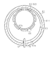
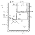
- FIG. 7 is a cross-sectional view taken along line 7-7 in FIG. It is sectional drawing which shows schematic structure of the oil separator of 4th Embodiment. It is sectional drawing which shows schematic structure of the oil separator of 5th Embodiment.
- FIG. 1 shows a fuel supply device 20 that supplies CNG (compressed natural gas), which is an example of gaseous fuel, to the internal combustion engine 11, and an internal combustion engine 11 that is operated by supplying CNG.
- CNG compressed natural gas
- FIG. 1 in the intake passage 12 of the internal combustion engine 11, a throttle valve 13 whose opening is adjusted according to the accelerator operation by the driver, and fuel injection for injecting CNG supplied from the fuel supply device 20.
- a valve 14 An air-fuel mixture consisting of intake air that has passed through the throttle valve 13 and CNG injected from the fuel injection valve 14 is combusted in the combustion chamber 16 in the cylinder 15.
- the piston 17 of the internal combustion engine 11 reciprocates, and the crankshaft that is the output shaft of the internal combustion engine 11 rotates in a predetermined rotation direction.
- the fuel supply device 20 is provided with a high-pressure fuel pipe 22 connected to a CNG tank 21 for storing CNG.
- the CNG flowing in the high-pressure fuel pipe 22 is reduced to a prescribed fuel pressure by a pressure regulator 23 provided in the middle of the high-pressure fuel pipe 22, and the reduced CNG is supplied to the delivery pipe 24.
- CNG in the delivery pipe 24 is injected into the intake passage 12 from the fuel injection valve 14.
- the pressure regulator 23 includes an electromagnetic shut-off valve 30, a pressure reducing valve 50, and an oil separator 60.
- the shutoff valve 30 is open when CNG is supplied to the internal combustion engine 11, and is closed when CNG is not supplied to the internal combustion engine 11.
- CNG flows from the CNG tank 21 into the body 40 of the pressure regulator 23 and passes through the shutoff valve 30.
- CNG that has passed through the shutoff valve 30 is reduced to a specified pressure by the pressure reducing valve 50 and flows into the oil separator 60.
- the oil separator 60 foreign substances contained in the CNG, for example, liquid such as oil, are removed from the CNG, and the CNG is guided to the delivery pipe 24.
- the oil separator 60 is provided in the lower part of the body 40.
- the oil separator 60 includes a drain tank 61 having a substantially cylindrical shape with a bottom, and the drain tank 61 is attached to the body 40 such that the upper opening is closed by the bottom surface of the body 40.
- a filter 62 having a cylindrical shape is provided in the drain tank 61, and a lower opening 62 a of the filter 62 is closed by a closing member 63. That is, the filter 62 and the blocking member 63 constitute a “separation part” disposed in an upper region in the drain tank 61, and this separation part removes foreign matters such as oil from the CNG flowing into the drain tank 61. To separate.
- the upper opening of the filter 62 is closed by the bottom surface of the body 40.
- An inflow part 64 through which CNG flows into the drain tank 61 is provided inside the filter 62.
- An outflow portion 65 through which CNG flows out of the drain tank 61 is provided outside the filter 62. Therefore, CNG that has flowed into the drain tank 61 through the inflow portion 64 passes from the inside toward the outside through the filter 62, and flows out of the drain tank 61, that is, out of the pressure regulator 23 through the outflow portion 65.
- foreign matters such as oil trapped by the filter 62 accumulate in the drain tank 61.
- a sensor 70 for detecting the position of the oil level in the drain tank 61 is attached to the side wall 611 of the drain tank 61.
- the sensor 70 is disposed above the bottom wall 612, specifically below the lower opening 62 a of the filter 62 and above the lower end of the closing member 63.
- the sensor 70 outputs a detection signal indicating that the liquid level has been detected.
- a communication hole 67 is formed through the lower end of the side wall 611 of the drain tank 61, and the communication hole 67 is closed by a manual valve 68.
- the closing member 63 will be described with reference to FIGS.
- the closing member 63 has a lid portion 81 that closes the lower opening 62 a of the filter 62, and a skirt 82 that protrudes downward from the periphery of the lid portion 81.
- the lid 81 is disposed above the sensor 70, and the lower end of the skirt 82 is disposed below the sensor 70.
- a skirt 82 is provided at the lower end of the skirt 82 as a baffle plate extending toward the side wall 611 of the drain tank 61. That is, the flange 83 is disposed between the sensor 70 and the bottom wall 612 of the drain tank 61 in the vertical direction.
- the drain tank 61, the sensor 70, and the closing member 63 constitute a “liquid retention device”.
- the collar portion 83 may be configured integrally with the skirt 82 and the lid portion 81.
- the closure member 63 may be configured by attaching a collar portion 83 formed separately from the skirt 82 and the lid portion 81 to the skirt 82.
- the collar portion 83 extends in the drain tank 61 over almost the entire cross section of the drain tank 61, and is configured to go upward as it approaches the side wall 611.
- a gap SP1 is provided between the tip (outer peripheral edge) 83a of the flange 83 and the side wall 611 of the drain tank 61 to allow the passage of liquid such as oil.
- the tip 83 a of the flange 83 is located on the radially outer side of the drain tank 61 with respect to the tip of the sensor 70.
- a plurality of communication holes 84 are provided side by side in the circumferential direction at the base end (inner peripheral edge) 83b of the collar part 83, which is a connection part of the collar part 83 to the skirt 82.
- one communication hole 84 may be provided at the base end 83 b of the flange 83.
- CNG flows into the drain tank 61 through the inflow portion 64, and oil contained in the CNG is captured by the filter 62.
- the oil trapped by the filter 62 flows downward along the skirt 82 of the closing member 63 and flows down through the base end 83 b of the flange 83, that is, through the communication hole 84 provided at the connection portion of the flange 83 to the skirt 82. And accumulates in the drain tank 61.
- the oil When the vibration is transmitted to the oil separator 60 while the oil is accumulated in the drain tank 61, the oil may be scattered or the liquid level may be undulated. However, such splashes of oil adhere to the lower surface of the collar part 83 or are rebounded by the collar part 83. That is, the oil accumulated in the drain tank 61 is suppressed from moving upward from the flange 83. Therefore, even if vibration is transmitted to the oil separator 60 in a state where the oil is accumulated in the drain tank 61, the oil is suppressed from adhering to the sensor 70.
- a gap SP1 exists between the flange 83 and the side wall 611 of the drain tank 61. Therefore, the oil accumulated in the drain tank 61 through the gap SP1 may reach a space above the flange 83 and adhere to the upper surface of the flange 83. Such oil flows from the upper surface of the flange portion 83 toward the lowermost portion of the flange portion 83, that is, the base end 83b. The oil that has moved to the base end 83 b of the flange 83 is returned to the space below the flange 83 through the communication hole 84.
- the following effects can be obtained. (1) When the amount of liquid in the drain tank 61 is small and the liquid level is located below the flange 83, it is confirmed that the oil droplets accumulated in the drain tank 61 adhere to the sensor 70. 83 can be regulated. Therefore, when the liquid level in the drain tank 61 is positioned below the sensor 70, the sensor 70 can be prevented from erroneously outputting a detection signal.
- a plurality of communication holes 84 are provided at the base end 83b of the flange 83. Therefore, the oil that adheres to the upper surface of the flange 83 and moves to the base end 83 b of the flange 83 can be returned to the space below the flange 83 through the communication hole 84.
- the flange 83 is configured to go upward as it approaches the side wall 611 of the drain tank 61. Therefore, the oil adhering to the upper surface of the collar 83 can be appropriately guided toward the base end 83b of the collar 83 provided with the plurality of communication holes 84. Therefore, oil can be prevented from collecting on the flange 83.
- the flange 83 may have any shape as long as it is disposed between the sensor 70 and the bottom wall 612 of the drain tank 61.
- the collar portion 83 ⁇ / b> A is configured to go downward as it approaches the side wall 611 of the drain tank 61. According to this configuration, the same effect as the above (1) can be obtained.
- the oil that is captured by the filter 62 and reaches the lower end of the skirt 82 flows along the upper surface of the flange 83A to the tip 83Aa of the flange 83A.
- the oil reaching the tip 83Aa of the flange 83A is guided to a space below the flange 83A through the gap SP1 between the tip 83Aa of the flange 83A and the side wall 611 of the drain tank 61. That is, according to this configuration, it is possible to prevent oil from being accumulated on the flange 83A even if the communication hole is not provided in the flange 83A.
- Oil splashes accumulated in the drain tank 61 may reach a space above the flange 83A via the gap SP1. In this case, when the oil based on the splash adheres to the upper surface of the collar portion 83A, the oil flows toward the tip 83Aa located below the base end of the collar portion 83A, and the collar portion 83A passes through the gap SP1. Is returned to the lower space.
- the flange 83A may be formed in parallel with the bottom wall 612 of the drain tank 61.
- the flange portions 83 and 83 ⁇ / b> A may be connected to a portion above the lower end of the skirt 82 as long as it is disposed between the sensor 70 and the bottom wall 612 of the drain tank 61.
- the plurality of communication holes 84 may be provided at any position between the distal end 83a and the proximal end 83b of the flange 83. If the plurality of communication holes 84 are provided in the flange 83, the flange 83 may be configured such that at least a part of the tip 83 a abuts against the side wall 611 of the drain tank 61. . According to this configuration, a liquid such as oil adhering to the upper surface of the flange 83 can be guided to a space below the flange 83 through the communication hole 84, and oil is prevented from collecting on the flange 83. be able to.
- the collar portions 83 and 83A may be made of a plate material provided with a large number of holes such as a net and a filter, that is, a porous material. In this case, even if the flanges 83 and 83A are arranged in parallel to the bottom wall 612 of the drain tank 61, it is possible to suppress oil from being accumulated on the flanges 83 and 83A.
- the baffle plate may extend from the side wall 611 of the drain tank 61 toward the skirt 82 of the closing member 63.
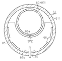
- the extending member 85 as a baffle plate is configured to go upward as it approaches the closing member 63.
- a gap SP ⁇ b> 2 may be interposed between the tip 85 a of the extending member 85 and the skirt 82.
- a plurality of communication holes 86 may be provided along the circumferential direction at the base end 85 b that is a connection portion connected to the side wall 611 in the extending member 85.
- the drain tank 61, the sensor 70, and the extending member 85 constitute a “liquid retention device”.
- the communication hole 86 may be provided at an arbitrary position between the distal end 85a and the proximal end 85b of the extending member 85. As long as a plurality of communication holes 86 are provided in the extending member 85, the extending member 85 may be configured such that at least a part of the distal end 85 a contacts the closing member 63. According to this configuration, a liquid such as oil adhering to the upper surface of the extending member 85 can be guided to a space below the extending member 85 through the communication hole 86, and the oil accumulates on the extending member 85. Can be suppressed.
- the extending member 85 ⁇ / b> A as a baffle plate is configured to go downward as approaching the closing member 63.
- a gap SP2 is interposed between the distal end 85Aa of the extending member 85A and the skirt 82. According to this configuration, it is possible to prevent oil from accumulating on the extension member 85A even if the communication hole is not provided in the extension member 85A.
- the extension members 85 and 85A may be made of a plate material provided with a large number of holes such as a net and a filter, that is, a porous material. In this case, even if the extending members 85 and 85A are arranged in parallel to the bottom wall 612 of the drain tank 61, it is possible to prevent oil from being accumulated on the extending members 85 and 85A.
- the flange portion 83 ⁇ / b> B is provided on the skirt 82 of the closing member 63, but also the extending member 85 ⁇ / b> B is provided on the side wall 611 of the drain tank 61.
- the collar portion 83B may be provided below the extending member 85B, or may be provided above the extending member 85B.
- the “baffle plate” is configured by the flange 83B and the extending member 85B.
- the oil separator 60 may have a configuration in which the inflow portion 64 is provided outside the filter 62 and the outflow portion 65 is provided inside the filter 62. In this case, CNG that has flowed into the drain tank 61 from the inflow portion 64 passes through the filter 62 from the outside to the inside, and flows out of the drain tank 61 from the outflow portion 65.
- a separation unit such as a filter 62 may be provided outside the drain tank 61. In this case, foreign matter such as oil separated from the CNG by the separation unit flows into the drain tank 61.
- the gaseous fuel flowing into the oil separator 60 may be a gaseous fuel other than CNG as long as it can be burned in the combustion chamber 16 of the internal combustion engine 11.
Landscapes
- Engineering & Computer Science (AREA)
- Chemical & Material Sciences (AREA)
- Combustion & Propulsion (AREA)
- Mechanical Engineering (AREA)
- General Engineering & Computer Science (AREA)
- Chemical Kinetics & Catalysis (AREA)
- General Chemical & Material Sciences (AREA)
- Oil, Petroleum & Natural Gas (AREA)
- Lubrication Details And Ventilation Of Internal Combustion Engines (AREA)
- Filtering Of Dispersed Particles In Gases (AREA)
Abstract
オイルセパレータは、CNG(圧縮天然ガス)から分離されたオイルを溜める、底壁を有するドレーンタンクと、底壁の上方に位置するようにドレーンタンクに設けられてそのドレーンタンク内の液面の位置を検出するセンサと、を備えている。また、オイルセパレータは、ドレーンタンク内においてセンサと底壁との間に設けられる鍔部を備えている。
Description
本発明は、気体燃料から分離されたオイルなどの液体を溜めるドレーンタンクを備える液体滞留装置と、その液体滞留装置を備えるオイルセパレータとに関する。
気体燃料を内燃機関に供給するための燃料供給装置には、気体燃料からオイルなどの液体を分離するオイルセパレータが設けられている(例えば、特許文献1参照)。このオイルセパレータのドレーンタンクの内部において上方の領域には、気体燃料から液体を分離するためのフィルタエレメントが設けられている。フィルタエレメントによって気体燃料から分離された液体は、ドレーンタンク内に溜まる。
近年では、ドレーンタンク内に溜まっている液体の量、すなわちドレーンタンク内における液面の位置を検出するセンサを設けたオイルセパレータの開発が進められている。こうしたオイルセパレータにあっては、ドレーンタンク内で液面が上昇し、センサが液体に浸ると、そのセンサは液面を検出したことを示す検出信号を出力する。
上記の燃料供給装置を備える車両では、車両の走行に伴って振動及び加速度が発生し、これらの振動及び加速度はオイルセパレータに伝達される。この際に、ドレーンタンク内で液面が揺れることにより、液体が飛び散ったり、その液面が波打ったりすることがある。この場合、実際にはセンサが液体に浸っていないにも拘わらず、液体の飛沫がセンサに付着することに起因して、センサが誤って検出信号を出力するおそれがある。
本発明の目的は、ドレーンタンク内で液面がセンサよりも下方に位置するときに、液体の飛沫がそのセンサへ付着することを抑制することができる液体滞留装置及びオイルセパレータを提供することにある。
上記課題を解決するための液体滞留装置は、気体燃料から分離された液体を溜める、底壁を有するドレーンタンクと、底壁の上方に位置するようにドレーンタンクに設けられてそのドレーンタンク内の液面の位置を検出するセンサと、を備える。また、この装置は、ドレーンタンク内においてセンサと底壁との間に設けられる邪魔板を備える。
上課題を解決するためのオイルセパレータは、上記の液体滞留装置と、気体燃料がドレーンタンク内に流入する際に通過する流入部と、を備える。また、オイルセパレータは、ドレーンタンク内に配置され、流入部を通じてそのドレーンタンク内に流入した気体燃料から液体を分離する分離部と、分離部を通過した気体燃料がドレーンタンクの外に流出する際に通過する流出部と、を備える。
以下、液体滞留装置及びオイルセパレータ60の第1実施形態を図1~図4に従って説明する。
図1には、気体燃料の一例であるCNG(圧縮天然ガス)を内燃機関11に供給する燃料供給装置20と、CNGの供給によって運転される内燃機関11と、が示されている。図1に示すように、内燃機関11の吸気通路12には、運転者によるアクセル操作に応じて開度が調整されるスロットルバルブ13と、燃料供給装置20から供給されたCNGを噴射する燃料噴射弁14と、が設けられている。スロットルバルブ13を通過した吸気と、燃料噴射弁14から噴射されたCNGと、からなる混合気が気筒15内の燃焼室16で燃焼する。これにより、内燃機関11のピストン17が往復動し、内燃機関11の出力軸であるクランク軸が所定の回転方向に回転する。
図1には、気体燃料の一例であるCNG(圧縮天然ガス)を内燃機関11に供給する燃料供給装置20と、CNGの供給によって運転される内燃機関11と、が示されている。図1に示すように、内燃機関11の吸気通路12には、運転者によるアクセル操作に応じて開度が調整されるスロットルバルブ13と、燃料供給装置20から供給されたCNGを噴射する燃料噴射弁14と、が設けられている。スロットルバルブ13を通過した吸気と、燃料噴射弁14から噴射されたCNGと、からなる混合気が気筒15内の燃焼室16で燃焼する。これにより、内燃機関11のピストン17が往復動し、内燃機関11の出力軸であるクランク軸が所定の回転方向に回転する。
燃料供給装置20には、CNGを貯留するCNGタンク21に接続される高圧燃料配管22が設けられている。高圧燃料配管22内を流動するCNGは、高圧燃料配管22の途中に設けられる圧力調整器23によって規定の燃料圧力に減圧され、減圧されたCNGがデリバリパイプ24に供給される。デリバリパイプ24内のCNGは、燃料噴射弁14から吸気通路12内に噴射される。
次に、図2を参照して、圧力調整器23について説明する。図2に示す矢印は鉛直方向を示しており、この圧力調整器23は鉛直方向に延びるように設置されている。
圧力調整器23は、電磁式の遮断弁30と、減圧弁50と、オイルセパレータ60と、を備えている。遮断弁30は、CNGを内燃機関11に供給する際には開放状態となる一方、CNGを内燃機関11に供給しない際には閉鎖状態となる。遮断弁30が開放状態である場合、CNGはCNGタンク21から圧力調整器23のボディ40内に流入し、遮断弁30を通過する。遮断弁30を通過したCNGは減圧弁50によって規定圧に減圧され、オイルセパレータ60内に流入する。オイルセパレータ60内において、CNGからそのCNGに含まれる異物、例えばオイルなどの液体が除去され、CNGはデリバリパイプ24に導かれる。
圧力調整器23は、電磁式の遮断弁30と、減圧弁50と、オイルセパレータ60と、を備えている。遮断弁30は、CNGを内燃機関11に供給する際には開放状態となる一方、CNGを内燃機関11に供給しない際には閉鎖状態となる。遮断弁30が開放状態である場合、CNGはCNGタンク21から圧力調整器23のボディ40内に流入し、遮断弁30を通過する。遮断弁30を通過したCNGは減圧弁50によって規定圧に減圧され、オイルセパレータ60内に流入する。オイルセパレータ60内において、CNGからそのCNGに含まれる異物、例えばオイルなどの液体が除去され、CNGはデリバリパイプ24に導かれる。
オイルセパレータ60は、ボディ40の下部に設けられている。このオイルセパレータ60は有底略筒状をなすドレーンタンク61を備えており、このドレーンタンク61は、その上部開口がボディ40の底面によって閉塞されるようにボディ40に取り付けられている。こうしたドレーンタンク61内には円筒形状をなすフィルタ62が設けられており、このフィルタ62の下部開口62aは閉塞部材63によって閉塞されている。すなわち、フィルタ62及び閉塞部材63は、ドレーンタンク61内において上方の領域に配置される「分離部」を構成しており、この分離部はドレーンタンク61内に流入したCNGからオイルなどの異物を分離する。フィルタ62の上部開口は、ボディ40の底面によって閉塞されている。
ドレーンタンク61内にCNGが流入する際に通過する流入部64はフィルタ62の内側に設けられている。CNGがドレーンタンク61外に流出する際に通過する流出部65はフィルタ62の外側に設けられている。そのため、流入部64を通じてドレーンタンク61内に流入したCNGは、フィルタ62を内側から外側に向けて通過し、流出部65を通じてドレーンタンク61の外、すなわち圧力調整器23の外に流出される。フィルタ62をCNGが通過する際にそのフィルタ62によって捕捉されたオイルなどの異物は、ドレーンタンク61内に溜まる。
ドレーンタンク61の側壁611には、ドレーンタンク61内のオイルの液面の位置を検出するためのセンサ70が取り付けられている。センサ70は、底壁612の上方、詳しくはフィルタ62の下部開口62aよりも下方であって、且つ閉塞部材63の下端よりも上方に配置されている。ドレーンタンク61内で液面が上昇し、センサ70がオイルに浸ると、センサ70は液面を検出したことを示す検出信号を出力する。
ドレーンタンク61の側壁611の下端には連通孔67が貫通して形成されており、この連通孔67は、手動式のバルブ68によって閉塞されている。
次に、図2及び図3を参照して、閉塞部材63について説明する。
次に、図2及び図3を参照して、閉塞部材63について説明する。
図2に示すように、閉塞部材63は、フィルタ62の下部開口62aを閉塞する蓋部81と、蓋部81の周縁から下方に突出するスカート82と、を有している。蓋部81はセンサ70よりも上方に配置され、スカート82の下端はセンサ70よりも下方に配置されている。
図2及び図3に示すように、スカート82の下端には、ドレーンタンク61の側壁611に向けて延出する邪魔板としての鍔部83が設けられている。すなわち、鍔部83は、上下方向においてセンサ70とドレーンタンク61の底壁612との間に配置されている。第1実施形態では、ドレーンタンク61、センサ70、及び閉塞部材63により、「液体滞留装置」が構成される。鍔部83は、スカート82及び蓋部81と一体に構成されていてもよい。あるいは、スカート82及び蓋部81とは別体として形成した鍔部83がスカート82に取り付けられて閉塞部材63が構成されていてもよい。
鍔部83は、ドレーンタンク61内においてそのドレーンタンク61の横断面のほぼ全体に広がっており、側壁611に近づくにつれて上方に向かうように構成されている。鍔部83の先端(外周縁)83aとドレーンタンク61の側壁611との間には、オイルなどの液体の通過を許容する程度の隙間SP1が介在している。鍔部83の先端83aは、センサ70の先端よりもドレーンタンク61の径方向外側に位置している。
スカート82に対する鍔部83の接続部位である鍔部83の基端(内周縁)83bには、複数の連通孔84が周方向に並んで設けられている。この鍔部83の基端83bには、複数の連通孔84の代わりに、一つの連通孔84が設けられていてもよい。
次に、図4を参照して、オイルセパレータ60の作用について説明する。以下の説明において、ドレーンタンク61内の液面が揺れていない静止状態では、液面が鍔部83よりも下方に位置しているものとする。
図4に示すように、CNGは流入部64を通じてドレーンタンク61内に流入し、そのCNGに含まれるオイルは、フィルタ62に捕捉される。フィルタ62に捕捉されたオイルは、閉塞部材63のスカート82に沿って下方に流れ、鍔部83の基端83b、すなわちスカート82に対する鍔部83の接続部位に設けられている連通孔84を通じて流下し、ドレーンタンク61内に溜まる。
ドレーンタンク61内にオイルが溜まっている状態でオイルセパレータ60に振動が伝達されると、オイルが飛び散ったり、液面が波打ったりすることがある。しかし、こうしたオイルの飛沫は、鍔部83の下面に付着したり、鍔部83により跳ね返されたりする。すなわち、ドレーンタンク61に溜まっているオイルが、鍔部83よりも上方に移動することが抑制される。したがって、ドレーンタンク61内にオイルが溜まっている状態でオイルセパレータ60に振動が伝達されても、オイルがセンサ70に付着することが抑制される。
鍔部83とドレーンタンク61の側壁611との間には隙間SP1が存在する。そのため、隙間SP1を通じて、ドレーンタンク61内に溜まっているオイルが、鍔部83よりも上方の空間に至り、鍔部83の上面に付着することがある。こうしたオイルは、鍔部83の上面を鍔部83の最下部、すなわち基端83bに向けて流れる。鍔部83の基端83bに移動したオイルが、連通孔84を通じて鍔部83よりも下方の空間に戻される。
上記第1実施形態によれば、以下に示す効果を得ることができる。
(1)ドレーンタンク61内の液量が少なく、液面が鍔部83よりも下方に位置している場合、ドレーンタンク61内に溜まっているオイルの飛沫がセンサ70へ付着することを鍔部83によって規制することができる。そのため、ドレーンタンク61内の液面がセンサ70よりも下方に位置するときに、センサ70が誤って検出信号を出力することを抑制することができる。
(1)ドレーンタンク61内の液量が少なく、液面が鍔部83よりも下方に位置している場合、ドレーンタンク61内に溜まっているオイルの飛沫がセンサ70へ付着することを鍔部83によって規制することができる。そのため、ドレーンタンク61内の液面がセンサ70よりも下方に位置するときに、センサ70が誤って検出信号を出力することを抑制することができる。
(2)鍔部83の基端83bには複数の連通孔84が設けられている。そのため、鍔部83の上面に付着し、鍔部83の基端83bに移動したオイルを、連通孔84を通じて鍔部83よりも下方の空間に戻すことができる。
(3)鍔部83は、ドレーンタンク61の側壁611に近づくにつれて上方に向かうように構成されている。そのため、鍔部83の上面に付着したオイルを、複数の連通孔84が設けられている鍔部83の基端83bに向けて適切に案内することができる。したがって、鍔部83上にオイルが溜まることを抑制することができる。
上記第1実施形態を以下のような別の実施形態及び変形例に変更してもよい。
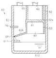
・鍔部83は、センサ70とドレーンタンク61の底壁612との間に配置されるのであれば、どのような形状であってもよい。例えば、図5に示すように、第2実施形態では、鍔部83Aはドレーンタンク61の側壁611に近づくにつれて下方に向かうように構成されている。この構成によれば、上記(1)と同等の効果を得ることができる。
・鍔部83は、センサ70とドレーンタンク61の底壁612との間に配置されるのであれば、どのような形状であってもよい。例えば、図5に示すように、第2実施形態では、鍔部83Aはドレーンタンク61の側壁611に近づくにつれて下方に向かうように構成されている。この構成によれば、上記(1)と同等の効果を得ることができる。
さらに、第2実施形態では、フィルタ62によって捕捉され、スカート82の下端に至ったオイルは、鍔部83Aの上面に沿ってその鍔部83Aの先端83Aaまで流れる。鍔部83Aの先端83Aaに至ったオイルは、鍔部83Aの先端83Aaとドレーンタンク61の側壁611との間の隙間SP1を通じて鍔部83Aよりも下方の空間に導かれる。すなわち、この構成によれば、鍔部83Aに連通孔が設けられていなくても、鍔部83A上にオイルが溜まることを抑制することができる。ドレーンタンク61内に溜まっているオイルの飛沫が隙間SP1を介して鍔部83Aよりも上方の空間に達することがある。この場合、飛沫に基づいたオイルが鍔部83Aの上面に付着すると、このオイルは、鍔部83Aの基端よりも下方に位置する先端83Aaに向けて流れ、上記隙間SP1を介して鍔部83Aよりも下方の空間に戻される。
上記鍔部83Aは、ドレーンタンク61の底壁612と平行に形成されてもよい。
・鍔部83,83Aは、センサ70とドレーンタンク61の底壁612との間に配置されるのであれば、スカート82における下端よりも上方の部位に接続されてもよい。
・鍔部83,83Aは、センサ70とドレーンタンク61の底壁612との間に配置されるのであれば、スカート82における下端よりも上方の部位に接続されてもよい。
・複数の連通孔84は、鍔部83の先端83aと基端83bとの間の任意の位置に設けられてもよい。
・鍔部83に複数の連通孔84が設けられているのであれば、鍔部83は、その先端83aの少なくとも一部がドレーンタンク61の側壁611に当設するように構成されていてもよい。この構成によれば、鍔部83の上面に付着したオイルなどの液体を、連通孔84を通じて鍔部83よりも下方の空間に導くことができ、鍔部83上にオイルが溜まることを抑制することができる。
・鍔部83に複数の連通孔84が設けられているのであれば、鍔部83は、その先端83aの少なくとも一部がドレーンタンク61の側壁611に当設するように構成されていてもよい。この構成によれば、鍔部83の上面に付着したオイルなどの液体を、連通孔84を通じて鍔部83よりも下方の空間に導くことができ、鍔部83上にオイルが溜まることを抑制することができる。
・鍔部83,83Aは、網及びフィルタなどの多数の孔が全体にわたって設けられている板材、すなわち多孔材料で構成されていてもよい。この場合、鍔部83,83Aが、ドレーンタンク61の底壁612に対して平行に配置されていても、鍔部83,83A上にオイルが溜まることを抑制することができる。
・邪魔板は、センサ70とドレーンタンク61の底壁612との間に配置されるのであれば、ドレーンタンク61の側壁611から閉塞部材63のスカート82に向けて延びていてもよい。
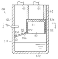
例えば、図6及び図7に示すように、第3実施形態では、邪魔板としての延出部材85は、閉塞部材63に近づくにつれて上方に向かうように構成されている。延出部材85の先端85aとスカート82との間には、隙間SP2が介在していてもよい。さらに、延出部材85において側壁611に接続される接続部位である基端85bに、周方向に沿って複数の連通孔86が設けられていてもよい。
この構成によれば、延出部材85の上面に付着したオイルは、その基端85bに向けて流れ、連通孔86を通じて延出部材85よりも下方の空間に戻される。これにより、延出部材85上にオイルが溜まることを抑制することができる。この場合、ドレーンタンク61、センサ70、及び延出部材85により、「液体滞留装置」が構成される。
連通孔86は、延出部材85の先端85aと基端85bとの間の任意の位置に設けてもよい。
延出部材85に複数の連通孔86が設けられているのであれば、延出部材85は、その先端85aの少なくとも一部が閉塞部材63に当設するように構成されていてもよい。この構成によれば、延出部材85の上面に付着したオイルなどの液体を、連通孔86を通じて延出部材85よりも下方の空間に導くことができ、延出部材85上にオイルが溜まることを抑制することができる。
延出部材85に複数の連通孔86が設けられているのであれば、延出部材85は、その先端85aの少なくとも一部が閉塞部材63に当設するように構成されていてもよい。この構成によれば、延出部材85の上面に付着したオイルなどの液体を、連通孔86を通じて延出部材85よりも下方の空間に導くことができ、延出部材85上にオイルが溜まることを抑制することができる。
・図8に示すように、第4実施形態では、邪魔板としての延出部材85Aは、閉塞部材63に近づくにつれて下方に向かうように構成されている。延出部材85Aの先端85Aaとスカート82との間には、隙間SP2が介在している。この構成によれば、延出部材85Aに連通孔が設けられていなくても、延出部材85A上にオイルが溜まることを抑制することができる。
・延出部材85,85Aは、網及びフィルタなどの多数の孔が全体にわたって設けられている板材、すなわち多孔材料で構成されていてもよい。この場合、延出部材85,85Aが、ドレーンタンク61の底壁612に対して平行に配置されていても、延出部材85,85A上にオイルが溜まることを抑制することができる。
・図9に示すように、第5実施形態では、閉塞部材63のスカート82に鍔部83Bが設けられるだけではなく、ドレーンタンク61の側壁611に延出部材85Bが設けられている。鍔部83Bは、延出部材85Bよりも下方に設けられていてもよく、もしくは延出部材85Bよりも上方に設けられていてもよい。この場合、鍔部83B及び延出部材85Bにより、「邪魔板」が構成される。
・オイルセパレータ60は、流入部64がフィルタ62の外側に設けられ、流出部65がフィルタ62の内側に設けられた構成であってもよい。この場合、流入部64からドレーンタンク61内に流入したCNGは、フィルタ62をその外側から内側に向けて通過し、流出部65からドレーンタンク61の外に流出する。
・邪魔板が、センサ70とドレーンタンク61の底壁612との間に配置されているのであれば、フィルタ62などの分離部が、ドレーンタンク61の外に設けられてもよい。この場合、ドレーンタンク61内に、分離部によってCNGから分離されたオイルなどの異物が流入する。
・オイルセパレータ60に流入する気体燃料は、内燃機関11の燃焼室16内で燃焼させることのできる燃料であれば、CNG以外の他の気体燃料であってもよい。
Claims (11)
- 気体燃料から分離された液体を溜める、底壁を有するドレーンタンクと、
前記底壁の上方に位置するように前記ドレーンタンクに設けられてそのドレーンタンク内の液面の位置を検出するセンサと、
前記ドレーンタンク内において前記センサと前記底壁との間に設けられる邪魔板と、を備える液体滞留装置。 - 請求項1に記載の液体滞留装置と、
気体燃料が前記ドレーンタンク内に流入する際に通過する流入部と、
前記ドレーンタンク内に配置され、前記流入部を通じてそのドレーンタンク内に流入した気体燃料から液体を分離する分離部と、
前記分離部を通過した気体燃料が前記ドレーンタンクの外に流出する際に通過する流出部と、
を備えるオイルセパレータ。 - 前記分離部は、
下部開口を有するとともに、前記センサよりも上方に配置される筒状のフィルタであって、そのフィルタを通過する気体燃料に含まれる液体を捕捉する前記フィルタと、
前記フィルタの下部開口を閉塞する閉塞部材と、を有し、
前記フィルタの内側及び外側の何れか一方に前記流入部が配置され、他方に前記流出部が配置されており、
前記邪魔板は、前記閉塞部材から前記ドレーンタンクの側壁に向けて延びる鍔部を含む
請求項2に記載のオイルセパレータ。 - 前記鍔部は前記ドレーンタンクの側壁に近づくにつれて上方に向かうように構成され、前記鍔部の先端は前記ドレーンタンクの側壁から離間しており、
前記鍔部は連通孔を有する
請求項3に記載のオイルセパレータ。 - 前記連通孔は前記鍔部の基端に設けられる
請求項4に記載のオイルセパレータ。 - 前記鍔部は前記ドレーンタンクの側壁に近づくにつれて下方に向かうように構成され、前記鍔部の先端は前記ドレーンタンクの側壁から離間している
請求項3に記載のオイルセパレータ。 - 前記鍔部は多孔材料で構成されている
請求項3~請求項6のいずれか一項に記載のオイルセパレータ。 - 前記邪魔板は前記ドレーンタンクの側壁から前記閉塞部材に向けて延びる延出部材をさらに含む
請求項3~請求項7のいずれか一項に記載のオイルセパレータ。 - 前記分離部は、
下部開口を有するとともに、前記センサよりも上方に配置される筒状のフィルタであって、そのフィルタを通過する気体燃料に含まれる液体を捕捉する前記フィルタと、
前記フィルタの下部開口を閉塞する閉塞部材と、を有し、
前記フィルタの内側及び外側の何れか一方に前記流入部が配置され、他方に前記流出部が配置されており、
前記邪魔板は前記ドレーンタンクの側壁から前記閉塞部材に向けて延びる延出部材を含む
請求項2に記載のオイルセパレータ。 - 前記延出部材は前記閉塞部材に近づくにつれて上方に向かうように構成され、前記延出部材の先端は前記閉塞部材から離間しており、
前記延出部材は連通孔を有する
請求項8又は請求項9に記載のオイルセパレータ。 - 前記延出部材は前記閉塞部材に近づくにつれて下方に向かうように構成され、前記延出部材の先端は前記閉塞部材から離間している
請求項8又は請求項9に記載のオイルセパレータ。
Priority Applications (1)
| Application Number | Priority Date | Filing Date | Title |
|---|---|---|---|
| CN201480057519.1A CN105658942B (zh) | 2013-10-21 | 2014-10-14 | 液体滞留装置以及具备该液体滞留装置的油分离器 |
Applications Claiming Priority (2)
| Application Number | Priority Date | Filing Date | Title |
|---|---|---|---|
| JP2013-218514 | 2013-10-21 | ||
| JP2013218514A JP6121869B2 (ja) | 2013-10-21 | 2013-10-21 | オイルセパレータ |
Publications (1)
| Publication Number | Publication Date |
|---|---|
| WO2015060163A1 true WO2015060163A1 (ja) | 2015-04-30 |
Family
ID=52992763
Family Applications (1)
| Application Number | Title | Priority Date | Filing Date |
|---|---|---|---|
| PCT/JP2014/077338 Ceased WO2015060163A1 (ja) | 2013-10-21 | 2014-10-14 | 液体滞留装置及びその液体滞留装置を備えるオイルセパレータ |
Country Status (2)
| Country | Link |
|---|---|
| JP (1) | JP6121869B2 (ja) |
| WO (1) | WO2015060163A1 (ja) |
Citations (6)
| Publication number | Priority date | Publication date | Assignee | Title |
|---|---|---|---|---|
| JPS5997475A (ja) * | 1982-11-19 | 1984-06-05 | ハスマン・コ−ポレ−シヨン | 油分離装置 |
| JPS62120184U (ja) * | 1986-01-23 | 1987-07-30 | ||
| JPH1162753A (ja) * | 1997-08-12 | 1999-03-05 | Nok Corp | 液体遮断弁装置 |
| JP2000205050A (ja) * | 1999-01-13 | 2000-07-25 | Toyota Motor Corp | 気体燃料車 |
| JP2003231500A (ja) * | 2002-02-07 | 2003-08-19 | Shimadzu Corp | リザーバタンク |
| WO2013141179A1 (ja) * | 2012-03-22 | 2013-09-26 | 愛三工業 株式会社 | オイルセパレータ及び気体燃料供給装置 |
-
2013
- 2013-10-21 JP JP2013218514A patent/JP6121869B2/ja active Active
-
2014
- 2014-10-14 WO PCT/JP2014/077338 patent/WO2015060163A1/ja not_active Ceased
Patent Citations (6)
| Publication number | Priority date | Publication date | Assignee | Title |
|---|---|---|---|---|
| JPS5997475A (ja) * | 1982-11-19 | 1984-06-05 | ハスマン・コ−ポレ−シヨン | 油分離装置 |
| JPS62120184U (ja) * | 1986-01-23 | 1987-07-30 | ||
| JPH1162753A (ja) * | 1997-08-12 | 1999-03-05 | Nok Corp | 液体遮断弁装置 |
| JP2000205050A (ja) * | 1999-01-13 | 2000-07-25 | Toyota Motor Corp | 気体燃料車 |
| JP2003231500A (ja) * | 2002-02-07 | 2003-08-19 | Shimadzu Corp | リザーバタンク |
| WO2013141179A1 (ja) * | 2012-03-22 | 2013-09-26 | 愛三工業 株式会社 | オイルセパレータ及び気体燃料供給装置 |
Also Published As
| Publication number | Publication date |
|---|---|
| JP6121869B2 (ja) | 2017-04-26 |
| CN105658942A (zh) | 2016-06-08 |
| JP2015081524A (ja) | 2015-04-27 |
Similar Documents
| Publication | Publication Date | Title |
|---|---|---|
| US9316131B2 (en) | Crankcase integrity breach detection | |
| US9260990B2 (en) | Crankcase integrity breach detection | |
| US9068486B2 (en) | Crankcase integrity breach detection | |
| US8011340B2 (en) | Oil pan | |
| KR101862958B1 (ko) | 플랩 밸브 장치 및 플랩 밸브 장치를 구비한 기액 분리 장치 | |
| JP6076885B2 (ja) | 蒸発燃料処理装置 | |
| US20130168392A1 (en) | Fuel Filler Port | |
| US10359016B2 (en) | Water separator with a water overflow secured by means of a float valve | |
| JP6493060B2 (ja) | Pcvバルブ | |
| JP6232707B2 (ja) | 水分捕集器およびそれを備える燃料フィルタ装置 | |
| JP4793392B2 (ja) | 燃料フィルタ | |
| JP2009133235A (ja) | オイルセパレータ | |
| US20170087490A1 (en) | Filter device | |
| JP2011074900A (ja) | エンジンのオイル分離装置 | |
| WO2015060163A1 (ja) | 液体滞留装置及びその液体滞留装置を備えるオイルセパレータ | |
| CN101854995A (zh) | 用于自通气排泄阀的设备、系统和方法 | |
| JP2013151905A (ja) | ブローバイガス処理装置のオイルセパレータ | |
| CN105658942B (zh) | 液体滞留装置以及具备该液体滞留装置的油分离器 | |
| JP5407617B2 (ja) | セジメンタ | |
| CN203742709U (zh) | 油分离器 | |
| EP3149296B1 (en) | Liquid return system for internal combustion engine | |
| KR100501340B1 (ko) | 연료 주입성 개선을 위한 연료 시스템 | |
| JP5806102B2 (ja) | 内燃機関のブローバイガス還流装置 | |
| EP2740909A1 (en) | Blow-by gas processing circuit for internal combustion engine | |
| JP5692149B2 (ja) | オイルセパレータ |
Legal Events
| Date | Code | Title | Description |
|---|---|---|---|
| 121 | Ep: the epo has been informed by wipo that ep was designated in this application |
Ref document number: 14856772 Country of ref document: EP Kind code of ref document: A1 |
|
| NENP | Non-entry into the national phase |
Ref country code: DE |
|
| 122 | Ep: pct application non-entry in european phase |
Ref document number: 14856772 Country of ref document: EP Kind code of ref document: A1 |