WO2015052881A1 - 冷凍サイクル装置 - Google Patents
冷凍サイクル装置 Download PDFInfo
- Publication number
- WO2015052881A1 WO2015052881A1 PCT/JP2014/004845 JP2014004845W WO2015052881A1 WO 2015052881 A1 WO2015052881 A1 WO 2015052881A1 JP 2014004845 W JP2014004845 W JP 2014004845W WO 2015052881 A1 WO2015052881 A1 WO 2015052881A1
- Authority
- WO
- WIPO (PCT)
- Prior art keywords
- refrigerant
- flow rate
- air
- compressor
- refrigeration cycle
- Prior art date
- Legal status (The legal status is an assumption and is not a legal conclusion. Google has not performed a legal analysis and makes no representation as to the accuracy of the status listed.)
- Ceased
Links
Images

Classifications
-
- B—PERFORMING OPERATIONS; TRANSPORTING
- B60—VEHICLES IN GENERAL
- B60H—ARRANGEMENTS OF HEATING, COOLING, VENTILATING OR OTHER AIR-TREATING DEVICES SPECIALLY ADAPTED FOR PASSENGER OR GOODS SPACES OF VEHICLES
- B60H1/00—Heating, cooling or ventilating [HVAC] devices
- B60H1/00642—Control systems or circuits; Control members or indication devices for heating, cooling or ventilating devices
- B60H1/00814—Control systems or circuits characterised by their output, for controlling particular components of the heating, cooling or ventilating installation
- B60H1/00878—Control systems or circuits characterised by their output, for controlling particular components of the heating, cooling or ventilating installation the components being temperature regulating devices
- B60H1/00899—Controlling the flow of liquid in a heat pump system
- B60H1/00921—Controlling the flow of liquid in a heat pump system where the flow direction of the refrigerant does not change and there is an extra subcondenser, e.g. in an air duct
-
- B—PERFORMING OPERATIONS; TRANSPORTING
- B60—VEHICLES IN GENERAL
- B60H—ARRANGEMENTS OF HEATING, COOLING, VENTILATING OR OTHER AIR-TREATING DEVICES SPECIALLY ADAPTED FOR PASSENGER OR GOODS SPACES OF VEHICLES
- B60H1/00—Heating, cooling or ventilating [HVAC] devices
- B60H1/00357—Air-conditioning arrangements specially adapted for particular vehicles
- B60H1/00385—Air-conditioning arrangements specially adapted for particular vehicles for vehicles having an electrical drive, e.g. hybrid or fuel cell
- B60H1/00392—Air-conditioning arrangements specially adapted for particular vehicles for vehicles having an electrical drive, e.g. hybrid or fuel cell for electric vehicles having only electric drive means
-
- B—PERFORMING OPERATIONS; TRANSPORTING
- B60—VEHICLES IN GENERAL
- B60H—ARRANGEMENTS OF HEATING, COOLING, VENTILATING OR OTHER AIR-TREATING DEVICES SPECIALLY ADAPTED FOR PASSENGER OR GOODS SPACES OF VEHICLES
- B60H1/00—Heating, cooling or ventilating [HVAC] devices
- B60H1/00642—Control systems or circuits; Control members or indication devices for heating, cooling or ventilating devices
- B60H1/00735—Control systems or circuits characterised by their input, i.e. by the detection, measurement or calculation of particular conditions, e.g. signal treatment, dynamic models
- B60H1/0075—Control systems or circuits characterised by their input, i.e. by the detection, measurement or calculation of particular conditions, e.g. signal treatment, dynamic models the input being solar radiation
-
- F—MECHANICAL ENGINEERING; LIGHTING; HEATING; WEAPONS; BLASTING
- F25—REFRIGERATION OR COOLING; COMBINED HEATING AND REFRIGERATION SYSTEMS; HEAT PUMP SYSTEMS; MANUFACTURE OR STORAGE OF ICE; LIQUEFACTION SOLIDIFICATION OF GASES
- F25B—REFRIGERATION MACHINES, PLANTS OR SYSTEMS; COMBINED HEATING AND REFRIGERATION SYSTEMS; HEAT PUMP SYSTEMS
- F25B1/00—Compression machines, plants or systems with non-reversible cycle
- F25B1/06—Compression machines, plants or systems with non-reversible cycle with compressor of jet type, e.g. using liquid under pressure
-
- F—MECHANICAL ENGINEERING; LIGHTING; HEATING; WEAPONS; BLASTING
- F25—REFRIGERATION OR COOLING; COMBINED HEATING AND REFRIGERATION SYSTEMS; HEAT PUMP SYSTEMS; MANUFACTURE OR STORAGE OF ICE; LIQUEFACTION SOLIDIFICATION OF GASES
- F25B—REFRIGERATION MACHINES, PLANTS OR SYSTEMS; COMBINED HEATING AND REFRIGERATION SYSTEMS; HEAT PUMP SYSTEMS
- F25B1/00—Compression machines, plants or systems with non-reversible cycle
- F25B1/10—Compression machines, plants or systems with non-reversible cycle with multi-stage compression
-
- F—MECHANICAL ENGINEERING; LIGHTING; HEATING; WEAPONS; BLASTING
- F25—REFRIGERATION OR COOLING; COMBINED HEATING AND REFRIGERATION SYSTEMS; HEAT PUMP SYSTEMS; MANUFACTURE OR STORAGE OF ICE; LIQUEFACTION SOLIDIFICATION OF GASES
- F25B—REFRIGERATION MACHINES, PLANTS OR SYSTEMS; COMBINED HEATING AND REFRIGERATION SYSTEMS; HEAT PUMP SYSTEMS
- F25B41/00—Fluid-circulation arrangements
- F25B41/20—Disposition of valves, e.g. of on-off valves or flow control valves
-
- F—MECHANICAL ENGINEERING; LIGHTING; HEATING; WEAPONS; BLASTING
- F25—REFRIGERATION OR COOLING; COMBINED HEATING AND REFRIGERATION SYSTEMS; HEAT PUMP SYSTEMS; MANUFACTURE OR STORAGE OF ICE; LIQUEFACTION SOLIDIFICATION OF GASES
- F25B—REFRIGERATION MACHINES, PLANTS OR SYSTEMS; COMBINED HEATING AND REFRIGERATION SYSTEMS; HEAT PUMP SYSTEMS
- F25B41/00—Fluid-circulation arrangements
- F25B41/30—Expansion means; Dispositions thereof
- F25B41/31—Expansion valves
- F25B41/34—Expansion valves with the valve member being actuated by electric means, e.g. by piezoelectric actuators
- F25B41/35—Expansion valves with the valve member being actuated by electric means, e.g. by piezoelectric actuators by rotary motors, e.g. by stepping motors
-
- F—MECHANICAL ENGINEERING; LIGHTING; HEATING; WEAPONS; BLASTING
- F25—REFRIGERATION OR COOLING; COMBINED HEATING AND REFRIGERATION SYSTEMS; HEAT PUMP SYSTEMS; MANUFACTURE OR STORAGE OF ICE; LIQUEFACTION SOLIDIFICATION OF GASES
- F25B—REFRIGERATION MACHINES, PLANTS OR SYSTEMS; COMBINED HEATING AND REFRIGERATION SYSTEMS; HEAT PUMP SYSTEMS
- F25B43/00—Arrangements for separating or purifying gases or liquids; Arrangements for vaporising the residuum of liquid refrigerant, e.g. by heat
- F25B43/006—Accumulators
-
- F—MECHANICAL ENGINEERING; LIGHTING; HEATING; WEAPONS; BLASTING
- F25—REFRIGERATION OR COOLING; COMBINED HEATING AND REFRIGERATION SYSTEMS; HEAT PUMP SYSTEMS; MANUFACTURE OR STORAGE OF ICE; LIQUEFACTION SOLIDIFICATION OF GASES
- F25B—REFRIGERATION MACHINES, PLANTS OR SYSTEMS; COMBINED HEATING AND REFRIGERATION SYSTEMS; HEAT PUMP SYSTEMS
- F25B5/00—Compression machines, plants or systems, with several evaporator circuits, e.g. for varying refrigerating capacity
- F25B5/04—Compression machines, plants or systems, with several evaporator circuits, e.g. for varying refrigerating capacity arranged in series
-
- B—PERFORMING OPERATIONS; TRANSPORTING
- B60—VEHICLES IN GENERAL
- B60H—ARRANGEMENTS OF HEATING, COOLING, VENTILATING OR OTHER AIR-TREATING DEVICES SPECIALLY ADAPTED FOR PASSENGER OR GOODS SPACES OF VEHICLES
- B60H1/00—Heating, cooling or ventilating [HVAC] devices
- B60H1/32—Cooling devices
- B60H2001/3286—Constructional features
- B60H2001/3298—Ejector-type refrigerant circuits
-
- F—MECHANICAL ENGINEERING; LIGHTING; HEATING; WEAPONS; BLASTING
- F25—REFRIGERATION OR COOLING; COMBINED HEATING AND REFRIGERATION SYSTEMS; HEAT PUMP SYSTEMS; MANUFACTURE OR STORAGE OF ICE; LIQUEFACTION SOLIDIFICATION OF GASES
- F25B—REFRIGERATION MACHINES, PLANTS OR SYSTEMS; COMBINED HEATING AND REFRIGERATION SYSTEMS; HEAT PUMP SYSTEMS
- F25B2341/00—Details of ejectors not being used as compression device; Details of flow restrictors or expansion valves
- F25B2341/001—Ejectors not being used as compression device
- F25B2341/0012—Ejectors with the cooled primary flow at high pressure
-
- F—MECHANICAL ENGINEERING; LIGHTING; HEATING; WEAPONS; BLASTING
- F25—REFRIGERATION OR COOLING; COMBINED HEATING AND REFRIGERATION SYSTEMS; HEAT PUMP SYSTEMS; MANUFACTURE OR STORAGE OF ICE; LIQUEFACTION SOLIDIFICATION OF GASES
- F25B—REFRIGERATION MACHINES, PLANTS OR SYSTEMS; COMBINED HEATING AND REFRIGERATION SYSTEMS; HEAT PUMP SYSTEMS
- F25B2400/00—General features or devices for refrigeration machines, plants or systems, combined heating and refrigeration systems or heat-pump systems, i.e. not limited to a particular subgroup of F25B
- F25B2400/04—Refrigeration circuit bypassing means
- F25B2400/0409—Refrigeration circuit bypassing means for the evaporator
-
- F—MECHANICAL ENGINEERING; LIGHTING; HEATING; WEAPONS; BLASTING
- F25—REFRIGERATION OR COOLING; COMBINED HEATING AND REFRIGERATION SYSTEMS; HEAT PUMP SYSTEMS; MANUFACTURE OR STORAGE OF ICE; LIQUEFACTION SOLIDIFICATION OF GASES
- F25B—REFRIGERATION MACHINES, PLANTS OR SYSTEMS; COMBINED HEATING AND REFRIGERATION SYSTEMS; HEAT PUMP SYSTEMS
- F25B2400/00—General features or devices for refrigeration machines, plants or systems, combined heating and refrigeration systems or heat-pump systems, i.e. not limited to a particular subgroup of F25B
- F25B2400/04—Refrigeration circuit bypassing means
- F25B2400/0411—Refrigeration circuit bypassing means for the expansion valve or capillary tube
-
- F—MECHANICAL ENGINEERING; LIGHTING; HEATING; WEAPONS; BLASTING
- F25—REFRIGERATION OR COOLING; COMBINED HEATING AND REFRIGERATION SYSTEMS; HEAT PUMP SYSTEMS; MANUFACTURE OR STORAGE OF ICE; LIQUEFACTION SOLIDIFICATION OF GASES
- F25B—REFRIGERATION MACHINES, PLANTS OR SYSTEMS; COMBINED HEATING AND REFRIGERATION SYSTEMS; HEAT PUMP SYSTEMS
- F25B2500/00—Problems to be solved
- F25B2500/31—Low ambient temperatures
-
- F—MECHANICAL ENGINEERING; LIGHTING; HEATING; WEAPONS; BLASTING
- F25—REFRIGERATION OR COOLING; COMBINED HEATING AND REFRIGERATION SYSTEMS; HEAT PUMP SYSTEMS; MANUFACTURE OR STORAGE OF ICE; LIQUEFACTION SOLIDIFICATION OF GASES
- F25B—REFRIGERATION MACHINES, PLANTS OR SYSTEMS; COMBINED HEATING AND REFRIGERATION SYSTEMS; HEAT PUMP SYSTEMS
- F25B2600/00—Control issues
- F25B2600/11—Fan speed control
- F25B2600/112—Fan speed control of evaporator fans
-
- F—MECHANICAL ENGINEERING; LIGHTING; HEATING; WEAPONS; BLASTING
- F25—REFRIGERATION OR COOLING; COMBINED HEATING AND REFRIGERATION SYSTEMS; HEAT PUMP SYSTEMS; MANUFACTURE OR STORAGE OF ICE; LIQUEFACTION SOLIDIFICATION OF GASES
- F25B—REFRIGERATION MACHINES, PLANTS OR SYSTEMS; COMBINED HEATING AND REFRIGERATION SYSTEMS; HEAT PUMP SYSTEMS
- F25B2600/00—Control issues
- F25B2600/25—Control of valves
- F25B2600/2501—Bypass valves
-
- F—MECHANICAL ENGINEERING; LIGHTING; HEATING; WEAPONS; BLASTING
- F25—REFRIGERATION OR COOLING; COMBINED HEATING AND REFRIGERATION SYSTEMS; HEAT PUMP SYSTEMS; MANUFACTURE OR STORAGE OF ICE; LIQUEFACTION SOLIDIFICATION OF GASES
- F25B—REFRIGERATION MACHINES, PLANTS OR SYSTEMS; COMBINED HEATING AND REFRIGERATION SYSTEMS; HEAT PUMP SYSTEMS
- F25B2600/00—Control issues
- F25B2600/25—Control of valves
- F25B2600/2513—Expansion valves
-
- F—MECHANICAL ENGINEERING; LIGHTING; HEATING; WEAPONS; BLASTING
- F25—REFRIGERATION OR COOLING; COMBINED HEATING AND REFRIGERATION SYSTEMS; HEAT PUMP SYSTEMS; MANUFACTURE OR STORAGE OF ICE; LIQUEFACTION SOLIDIFICATION OF GASES
- F25B—REFRIGERATION MACHINES, PLANTS OR SYSTEMS; COMBINED HEATING AND REFRIGERATION SYSTEMS; HEAT PUMP SYSTEMS
- F25B2600/00—Control issues
- F25B2600/25—Control of valves
- F25B2600/2515—Flow valves
-
- F—MECHANICAL ENGINEERING; LIGHTING; HEATING; WEAPONS; BLASTING
- F25—REFRIGERATION OR COOLING; COMBINED HEATING AND REFRIGERATION SYSTEMS; HEAT PUMP SYSTEMS; MANUFACTURE OR STORAGE OF ICE; LIQUEFACTION SOLIDIFICATION OF GASES
- F25B—REFRIGERATION MACHINES, PLANTS OR SYSTEMS; COMBINED HEATING AND REFRIGERATION SYSTEMS; HEAT PUMP SYSTEMS
- F25B2600/00—Control issues
- F25B2600/25—Control of valves
- F25B2600/2519—On-off valves
-
- F—MECHANICAL ENGINEERING; LIGHTING; HEATING; WEAPONS; BLASTING
- F25—REFRIGERATION OR COOLING; COMBINED HEATING AND REFRIGERATION SYSTEMS; HEAT PUMP SYSTEMS; MANUFACTURE OR STORAGE OF ICE; LIQUEFACTION SOLIDIFICATION OF GASES
- F25B—REFRIGERATION MACHINES, PLANTS OR SYSTEMS; COMBINED HEATING AND REFRIGERATION SYSTEMS; HEAT PUMP SYSTEMS
- F25B2700/00—Sensing or detecting of parameters; Sensors therefor
- F25B2700/19—Pressures
- F25B2700/193—Pressures of the compressor
- F25B2700/1931—Discharge pressures
-
- F—MECHANICAL ENGINEERING; LIGHTING; HEATING; WEAPONS; BLASTING
- F25—REFRIGERATION OR COOLING; COMBINED HEATING AND REFRIGERATION SYSTEMS; HEAT PUMP SYSTEMS; MANUFACTURE OR STORAGE OF ICE; LIQUEFACTION SOLIDIFICATION OF GASES
- F25B—REFRIGERATION MACHINES, PLANTS OR SYSTEMS; COMBINED HEATING AND REFRIGERATION SYSTEMS; HEAT PUMP SYSTEMS
- F25B2700/00—Sensing or detecting of parameters; Sensors therefor
- F25B2700/21—Temperatures
- F25B2700/2103—Temperatures near a heat exchanger
-
- F—MECHANICAL ENGINEERING; LIGHTING; HEATING; WEAPONS; BLASTING
- F25—REFRIGERATION OR COOLING; COMBINED HEATING AND REFRIGERATION SYSTEMS; HEAT PUMP SYSTEMS; MANUFACTURE OR STORAGE OF ICE; LIQUEFACTION SOLIDIFICATION OF GASES
- F25B—REFRIGERATION MACHINES, PLANTS OR SYSTEMS; COMBINED HEATING AND REFRIGERATION SYSTEMS; HEAT PUMP SYSTEMS
- F25B2700/00—Sensing or detecting of parameters; Sensors therefor
- F25B2700/21—Temperatures
- F25B2700/2104—Temperatures of an indoor room or compartment
-
- F—MECHANICAL ENGINEERING; LIGHTING; HEATING; WEAPONS; BLASTING
- F25—REFRIGERATION OR COOLING; COMBINED HEATING AND REFRIGERATION SYSTEMS; HEAT PUMP SYSTEMS; MANUFACTURE OR STORAGE OF ICE; LIQUEFACTION SOLIDIFICATION OF GASES
- F25B—REFRIGERATION MACHINES, PLANTS OR SYSTEMS; COMBINED HEATING AND REFRIGERATION SYSTEMS; HEAT PUMP SYSTEMS
- F25B2700/00—Sensing or detecting of parameters; Sensors therefor
- F25B2700/21—Temperatures
- F25B2700/2106—Temperatures of fresh outdoor air
-
- F—MECHANICAL ENGINEERING; LIGHTING; HEATING; WEAPONS; BLASTING
- F25—REFRIGERATION OR COOLING; COMBINED HEATING AND REFRIGERATION SYSTEMS; HEAT PUMP SYSTEMS; MANUFACTURE OR STORAGE OF ICE; LIQUEFACTION SOLIDIFICATION OF GASES
- F25B—REFRIGERATION MACHINES, PLANTS OR SYSTEMS; COMBINED HEATING AND REFRIGERATION SYSTEMS; HEAT PUMP SYSTEMS
- F25B2700/00—Sensing or detecting of parameters; Sensors therefor
- F25B2700/21—Temperatures
- F25B2700/2115—Temperatures of a compressor or the drive means therefor
- F25B2700/21152—Temperatures of a compressor or the drive means therefor at the discharge side of the compressor
-
- F—MECHANICAL ENGINEERING; LIGHTING; HEATING; WEAPONS; BLASTING
- F25—REFRIGERATION OR COOLING; COMBINED HEATING AND REFRIGERATION SYSTEMS; HEAT PUMP SYSTEMS; MANUFACTURE OR STORAGE OF ICE; LIQUEFACTION SOLIDIFICATION OF GASES
- F25B—REFRIGERATION MACHINES, PLANTS OR SYSTEMS; COMBINED HEATING AND REFRIGERATION SYSTEMS; HEAT PUMP SYSTEMS
- F25B2700/00—Sensing or detecting of parameters; Sensors therefor
- F25B2700/21—Temperatures
- F25B2700/2117—Temperatures of an evaporator
-
- Y—GENERAL TAGGING OF NEW TECHNOLOGICAL DEVELOPMENTS; GENERAL TAGGING OF CROSS-SECTIONAL TECHNOLOGIES SPANNING OVER SEVERAL SECTIONS OF THE IPC; TECHNICAL SUBJECTS COVERED BY FORMER USPC CROSS-REFERENCE ART COLLECTIONS [XRACs] AND DIGESTS
- Y02—TECHNOLOGIES OR APPLICATIONS FOR MITIGATION OR ADAPTATION AGAINST CLIMATE CHANGE
- Y02B—CLIMATE CHANGE MITIGATION TECHNOLOGIES RELATED TO BUILDINGS, e.g. HOUSING, HOUSE APPLIANCES OR RELATED END-USER APPLICATIONS
- Y02B30/00—Energy efficient heating, ventilation or air conditioning [HVAC]
- Y02B30/70—Efficient control or regulation technologies, e.g. for control of refrigerant flow, motor or heating
Definitions
- the present invention relates to a refrigeration cycle apparatus including an ejector.
- Patent Document 1 discloses a refrigeration cycle apparatus that is applied to an air conditioner and that heats blown air (fluid to be heated) blown into the air-conditioning target space in a heating operation mode in which the air-conditioning target space is heated. Yes.
- an indoor condenser heat radiator
- an outdoor heat exchanger evaporator
- the indoor condenser converts the heat absorbed by the refrigerant from the outside air in the outdoor heat exchanger
- the blast air is heated by dissipating heat to the blast air.
- the refrigerant evaporating temperature in the outdoor heat exchanger is lowered to an extremely low temperature, the pressure of the refrigerant sucked out of the outdoor heat exchanger and sucked into the compressor is lowered. Density decreases. As a result, the flow rate (mass flow rate) of the high-pressure refrigerant discharged from the compressor and flowing into the indoor condenser decreases, and the heating capacity of the blown air in the indoor condenser decreases.
- an object of the present invention is to provide a refrigeration cycle apparatus capable of suppressing a decrease in the heating capacity of a heat target fluid in a radiator when the temperature of the heat absorption target fluid is decreased.
- a refrigeration cycle apparatus includes a compressor that compresses and discharges a refrigerant, and a high-pressure refrigerant that is discharged from the compressor.
- the heat exchanger exchanges heat with the fluid to be heated to radiate the high-pressure refrigerant, the decompressor to depressurize the refrigerant flowing out of the radiator, and the heat exchange between the low-pressure refrigerant decompressed by the decompressor and the heat-absorbing fluid And an evaporator for evaporating the low-pressure refrigerant and an ejector.
- the ejector sucks the refrigerant downstream of the evaporator from the refrigerant suction port and sucks the refrigerant from the jet refrigerant and the refrigerant suction port by the suction action of the high-speed jet refrigerant jetted from the nozzle part that depressurizes the high-pressure refrigerant discharged from the compressor.
- a pressure increasing unit is provided for increasing the pressure of the mixed refrigerant with the sucked suction refrigerant and causing the mixed refrigerant to flow out to the suction port side of the compressor.
- the flow rate (mass flow rate) of the high-pressure refrigerant discharged from the compressor and flowing into the radiator is low even under operating conditions in which the temperature of the endothermic fluid is lowered and the refrigerant evaporation temperature in the evaporator must be lowered. It can suppress that it decreases. As a result, even if the temperature of the heat absorption target fluid is reduced, it is possible to suppress a reduction in the heating capability of the heat target fluid in the radiator.
- the heating capacity of the fluid to be heated in the radiator is the ability to heat the fluid to be heated at a desired flow rate until the temperature reaches a desired temperature.
- the enthalpy of the refrigerant on the inlet side of the radiator can be defined using a value obtained by integrating the enthalpy difference obtained by subtracting the enthalpy of the outlet side refrigerant from the refrigerant flow rate (mass flow rate) flowing through the radiator.
- the vapor compression refrigeration cycle apparatus 10 is applied to a vehicle air conditioner 1 for an electric vehicle that obtains a driving force for vehicle traveling from a traveling electric motor.
- the refrigeration cycle apparatus 10 fulfills the function of cooling or heating the blown air blown into the vehicle interior that is the air-conditioning target space in the vehicle air conditioner 1. Therefore, the fluid to be heated in the present embodiment is blown air that is blown into the passenger compartment.
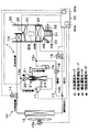
- the refrigeration cycle apparatus 10 includes a refrigerant circuit in a cooling operation mode for cooling the passenger compartment, a refrigerant circuit in a dehumidifying heating operation mode for heating while dehumidifying the passenger compartment, and a refrigerant in a heating operation mode for heating the passenger compartment.
- the circuit and the refrigerant circuit in the strong heating operation mode for heating the blown air with a heating capability higher than that in the heating operation mode at the time of low outside air temperature or the like can be switched.
- the refrigerant flow in the refrigerant circuit in the cooling operation mode is indicated by white arrows
- the refrigerant flow in the refrigerant circuit in the dehumidifying heating operation mode is indicated by hatched arrows
- the refrigerant flow in the refrigerant circuit in the strong heating operation mode is indicated by black arrows.
- an HFC-based refrigerant (specifically, R134a) is employed as the refrigerant, and the vapor compression subcritical refrigeration in which the high-pressure side refrigerant pressure does not exceed the refrigerant critical pressure.
- the refrigerant critical pressure Constitutes a cycle.
- coolants for example, R1234yf.
- refrigeration oil for lubricating the compressor 11 is mixed in the refrigerant, and a part of the refrigeration oil circulates in the cycle together with the refrigerant.
- the compressor 11 is disposed in the vehicle bonnet, and sucks the refrigerant in the refrigeration cycle apparatus 10 to increase the pressure until it becomes a high-pressure refrigerant and discharge it.
- the compressor 11 of the present embodiment is an electric compressor configured by housing a fixed capacity type compression mechanism and an electric motor that drives the compression mechanism in one housing.
- various compression mechanisms such as a scroll-type compression mechanism and a vane-type compression mechanism can be employed. Further, the operation (rotation speed) of the electric motor is controlled by a control signal output from the air conditioning control device 40 described later, and either an AC motor or a DC motor may be adopted.
- the refrigerant inlet of the first branch portion 13 a that branches the flow of the refrigerant discharged from the compressor 11 is connected to the discharge port side of the compressor 11.
- the first branch portion 13a is formed of a three-way joint, and one of the three inflow / outflow ports is a refrigerant inflow port, and the remaining two are the refrigerant outflow ports.
- Such a three-way joint may be formed by joining pipes having different pipe diameters, or may be formed by providing a plurality of refrigerant passages in a metal block or a resin block.
- the refrigerant inlet side of the indoor condenser 12 is connected to one refrigerant outlet of the first branch part 13a, and the nozzle opening / closing valve 22 is connected to the other refrigerant outlet of the first branch part 13a.
- the inlet side of the nozzle portion 21a of the ejector 21 is connected via the via. The detailed configuration of the nozzle part on-off valve 22 and the ejector 21 will be described later.
- the indoor condenser 12 is disposed in a casing 31 of an indoor air conditioning unit 30 to be described later, and exchanges heat between the high-pressure refrigerant discharged from the compressor 11 and blown air that has passed through the indoor evaporator 20 to be described later. It is a radiator that dissipates heat from the refrigerant.
- the inlet side of the heating expansion valve 14 is connected to the refrigerant outlet side of the indoor condenser 12.
- the heating expansion valve 14 is a decompression device that decompresses the high-pressure refrigerant discharged from the compressor 11 at least in the heating operation mode, and displaces the valve body configured to be able to change the throttle opening.
- an electric variable throttle mechanism that includes an electric actuator including a stepping motor that changes the throttle opening.
- the heating expansion valve 14 of the present embodiment is configured by a variable throttle mechanism with a fully open function that functions as a simple refrigerant passage without exhibiting a refrigerant decompression action by fully opening the throttle opening.
- the operation of the heating expansion valve 14 is controlled by a control signal output from the air conditioning control device 40.
- the refrigerant inlet side of the outdoor heat exchanger 15 is connected to the outlet side of the heating expansion valve 14.
- the outdoor heat exchanger 15 is a heat exchanger that is arranged on the front side in the vehicle bonnet and exchanges heat between the refrigerant on the downstream side of the indoor condenser 12 that circulates inside and the outside air blown from the blower fan 15a.
- the outdoor heat exchanger 15 functions as a radiator that dissipates high-pressure refrigerant at least in the cooling operation mode, and in the heating operation mode and the strong heating operation mode, the heating expansion valve 14 that is a decompression device. It functions as an evaporator that evaporates the low-pressure refrigerant depressurized in, and exerts an endothermic effect.
- the blower fan 15a is an electric blower in which the operation rate, that is, the rotation speed (the amount of blown air) is controlled by the control voltage output from the air conditioning control device 40.
- the refrigerant outlet side of the outdoor heat exchanger 15 is connected to the refrigerant inlet of the second branch part 13b that branches the flow of the refrigerant that has flowed out of the outdoor heat exchanger 15.
- the basic configuration of the second branch portion 13b is the same as that of the first branch portion 13a.
- the refrigerant inlet side of the cooling expansion valve 16 is connected to one refrigerant outlet of the second branch portion 13b, and the refrigerant flowing out of the second branch portion 13b is upstream of an accumulator 19 to be described later at the other refrigerant outlet.
- An accumulator side passage 17 that leads to the side is connected.
- the basic configuration of the cooling expansion valve 16 is the same as that of the heating expansion valve 14. Further, the cooling expansion valve 16 of the present embodiment has only a fully open function that fully opens the refrigerant passage from the refrigerant outlet side of the outdoor heat exchanger 15 to the refrigerant inlet side of the indoor evaporator 20 when the throttle opening is fully opened. First, it is composed of a variable throttle mechanism with a full-close function that closes the refrigerant passage when the throttle opening is fully closed.
- the refrigerant inlet side of the indoor evaporator 20 is connected to the outlet side of the cooling expansion valve 16.
- the indoor evaporator 20 is arranged in the casing 31 of the indoor air conditioning unit 30 on the upstream side of the blower air flow from the indoor condenser 12.
- the indoor evaporator 20 is a cooling system that cools the blown air by evaporating the refrigerant circulating in the cooling operation mode and the dehumidifying and heating operation mode by exchanging heat with the blown air before passing through the indoor condenser 12. Heat exchanger.
- the inlet side of the accumulator 19 is connected to the refrigerant outlet side of the indoor evaporator 20 via a junction 13c.
- the accumulator 19 is a gas-liquid separator that separates the gas-liquid refrigerant flowing into the accumulator 19 and stores excess refrigerant in the cycle.
- the merging portion 13c is configured by a three-way joint similar to the first and second branch portions 13a and 13b, and two of the three inflow / outflow ports are refrigerant inlets, and the remaining one is a refrigerant outflow port. Is.
- the outlet side of the accumulator side passage 17 is connected to the other refrigerant inlet of the merging portion 13c of the present embodiment.
- the accumulator side passage 17 is provided with a heating on-off valve 18 that opens and closes the accumulator side passage 17.
- the heating on / off valve 18 is an electromagnetic valve whose opening / closing operation is controlled by a control voltage output from the air conditioning control device 40.
- the refrigerant suction port 21d side of the ejector 21 is connected to the gas phase refrigerant outlet of the accumulator 19.
- the ejector 21 sucks the gas-phase refrigerant flowing out from the accumulator 19 from the refrigerant suction port 21d by injecting the high-pressure refrigerant flowing out from the other refrigerant outlet of the first branch portion 13a at a high speed, and injects it. It functions to convert the kinetic energy of the mixed refrigerant of the refrigerant and the suction refrigerant into pressure energy.
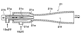
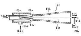
- the ejector 21 includes a nozzle portion 21a and a body portion 21b.
- the nozzle portion 21a is formed of a substantially cylindrical metal (for example, a stainless alloy) that gradually tapers in the flow direction of the refrigerant.
- the nozzle 21a is decompressed in an isentropic manner by reducing the refrigerant flowing into the inside.
- the refrigerant is injected from a refrigerant injection port provided on the most downstream side.
- the nozzle part 21a of the present embodiment is configured as a Laval nozzle.
- the nozzle portion 21a is set such that the flow rate of the injected refrigerant injected from the refrigerant injection port is equal to or higher than the sonic speed in the strong heating operation mode described later.
- the flow rate of the refrigerant discharged from the compressor 11 is set as a discharge refrigerant flow rate Gr
- the flow rate of the refrigerant flowing into the nozzle portion 21a of the ejector 21 is set as the ejector side refrigerant flow rate Gn
- the flow rate of the refrigerant flowing into the indoor condenser 12 is set.
- the pressure reduction characteristic (flow rate characteristic) of the nozzle portion 21a is set so as to satisfy the following formula F1.
- the discharge refrigerant flow rate Gr, the ejector side refrigerant flow rate Gn, and the radiator side refrigerant flow rate Gc are all mass flow rates, and the discharge refrigerant flow rate Gr is the sum of the ejector side refrigerant flow rate Gn and the radiator side refrigerant flow rate Gc. It becomes.
- the body portion 21b is formed of a substantially cylindrical metal (for example, aluminum), functions as a fixing member that supports and fixes the nozzle portion 21a therein, and forms the outer shell of the ejector 21. More specifically, the nozzle portion 21a is fixed by press-fitting so as to be accommodated inside the longitudinal end of the body portion 21b. Therefore, the refrigerant does not leak from the fixed portion (press-fit portion) between the nozzle portion 21a and the body portion 21b.
- a substantially cylindrical metal for example, aluminum
- a refrigerant suction port 21d provided so as to penetrate the inside and outside of the outer peripheral surface of the body portion 21b and communicate with the refrigerant injection port of the nozzle portion 21a is provided in a portion corresponding to the outer peripheral side of the nozzle portion 21a. Is formed.
- the refrigerant suction port 21d is a through hole that sucks the refrigerant flowing out from the gas-phase refrigerant outlet of the accumulator 19 into the ejector 21 by the suction action of the jet refrigerant injected from the nozzle portion 21a.
- a suction passage 21e that guides the suction refrigerant sucked from the refrigerant suction port 21d to the refrigerant injection port side of the nozzle portion 21a, and the ejector 21 from the refrigerant suction port 21d through the suction passage 21e.
- a diffuser portion 21f is formed as a pressure increasing portion that mixes the suction refrigerant flowing into the inside and the injection refrigerant to increase the pressure.
- the suction passage 21e is formed by a space between the outer peripheral side around the tapered tip of the nozzle portion 21a and the inner peripheral side of the body portion 21b.
- the refrigerant passage area of the suction passage 21e is in the refrigerant flow direction. It is gradually shrinking. Thereby, the flow rate of the suction refrigerant flowing through the suction passage 21e is gradually increased, and the energy loss (mixing loss) when the suction refrigerant and the injection refrigerant are mixed in the diffuser portion 21f is reduced.
- the diffuser portion 21f is arranged to be continuous with the outlet of the suction passage, and is formed by a space that gradually expands the refrigerant passage area.
- the cross-sectional shape in the axial section of the inner peripheral wall surface of the body portion 21b forming the diffuser portion 21f of the present embodiment is formed by combining a plurality of curves. And since the degree of spread of the refrigerant passage cross-sectional area of the diffuser portion 21f gradually increases in the refrigerant flow direction and then decreases again, the refrigerant can be increased in an isentropic manner.
- the suction port side of the compressor 11 is connected to the refrigerant outlet of the diffuser portion 21f of the ejector 21.
- the refrigerant passage connecting the other refrigerant outlet of the first branch portion 13a and the refrigerant inlet of the nozzle portion 21a of the ejector 21 is provided with a nozzle portion opening / closing valve 22 as an opening / closing device for opening and closing the refrigerant passage. Is arranged.
- the nozzle part on-off valve 22 is constituted by a non-energized closed type (so-called normally closed type) electromagnetic valve, and its operation is controlled by a control voltage output from the air conditioning control device 40.
- the air conditioning control device 40 opens the nozzle part opening / closing valve 22, whereby the refrigerant discharged from the compressor 11 flows into the nozzle part 21a, and the diffuser part 21f supplies the mixed refrigerant of the injected refrigerant and the suction refrigerant. It is possible to switch to a boosting refrigerant circuit for boosting pressure. On the other hand, the air-conditioning control device 40 can switch to the non-pressurization refrigerant circuit that does not increase the pressure of the mixed refrigerant in the diffuser portion 21f by closing the nozzle portion on-off valve 22.
- the nozzle part on-off valve 22 of this embodiment is an example of a refrigerant circuit switching part.
- the indoor air conditioning unit 30 is for blowing out the blown air whose temperature has been adjusted by the refrigeration cycle apparatus 10 into the vehicle interior, and is disposed inside the instrument panel (instrument panel) at the forefront of the vehicle interior. Furthermore, the indoor air conditioning unit 30 is configured by housing a blower 32, the indoor evaporator 20, the indoor condenser 12 and the like in a casing 31 forming an outer shell thereof.
- the casing 31 forms an air passage for the blown air blown into the passenger compartment, and is formed of a resin (for example, polypropylene) having a certain degree of elasticity and excellent in strength.
- An inside / outside air switching device 33 as an inside / outside air switching unit that switches and introduces inside air (vehicle compartment air) and outside air (vehicle compartment outside air) into the casing 31 is arranged on the most upstream side of the blown air flow in the casing 31. ing.
- the inside / outside air switching device 33 continuously adjusts the opening area of the inside air introduction port through which the inside air is introduced into the casing 31 and the outside air introduction port through which the outside air is introduced by the inside / outside air switching door, so that the air volume of the inside air and the air volume of the outside air are adjusted.
- the air volume ratio is continuously changed.
- the inside / outside air switching door is driven by an electric actuator for the inside / outside air switching door, and the operation of the electric actuator is controlled by a control signal output from the air conditioning control device 40.
- a blower 32 that blows the air sucked through the inside / outside air switching device 33 toward the vehicle interior is disposed on the downstream side of the blowing air flow of the inside / outside air switching device 33.
- the blower 32 is an electric blower that drives a centrifugal multiblade fan (sirocco fan) with an electric motor, and the number of rotations (air flow rate) is controlled by a control voltage output from the air conditioning control device 40.
- the indoor evaporator 20 and the indoor condenser 12 are arranged in this order with respect to the flow of the blown air. Further, a cold air bypass passage 35 is formed in the casing 31 to flow the blown air that has passed through the indoor evaporator 20 to the downstream side by bypassing the indoor condenser 12.
- the blast air heated by the indoor condenser 12 and the blast air not heated by the indoor condenser 12 through the cold air bypass passage 35 are mixed on the downstream side of the blast air flow of the indoor condenser 12.
- a mixing space is provided.
- the opening hole which blows off the ventilation air (air-conditioning wind) mixed in the mixing space to the vehicle interior which is an air-conditioning object space is arrange
- the opening hole includes a face opening hole that blows air-conditioned air toward the upper body of the passenger in the passenger compartment, a foot opening hole that blows air-conditioned air toward the feet of the passenger, and an inner surface of the front window glass of the vehicle.
- a defroster opening hole (both not shown) for blowing the conditioned air toward is provided. The air flow downstream of these face opening holes, foot opening holes, and defroster opening holes is connected to the face air outlet, foot air outlet, and defroster air outlet provided in the vehicle interior via ducts that form air passages, respectively. Neither is shown).
- the air mix door 34 adjusts the air volume ratio between the air volume that passes through the indoor condenser 12 and the air volume that passes through the cold air bypass passage 35, thereby adjusting the temperature of the conditioned air mixed in the mixing space.
- the temperature of the blast air (air conditioned air) blown out from each outlet to the vehicle interior is adjusted.
- the air mix door 34 constitutes a temperature adjustment unit that adjusts the temperature of the conditioned air blown into the vehicle interior.
- the air mix door 34 is driven by an electric actuator for driving the air mix door, and the operation of the electric actuator is controlled by a control signal output from the air conditioning control device 40.
- a face door for adjusting the opening area of the face opening hole a foot door for adjusting the opening area of the foot opening hole, and a defroster opening, respectively.
- a defroster door (both not shown) for adjusting the opening area of the hole is disposed.
- These face doors, foot doors, and defroster doors constitute an opening hole mode switching unit that switches the opening hole mode, and are linked to an electric actuator for driving the outlet mode door via a link mechanism or the like. And rotated.
- the operation of this electric actuator is also controlled by a control signal output from the air conditioning control device 40.
- a face mode in which the face air outlet is fully opened and air is blown out from the face air outlet toward the upper body of the passenger in the passenger compartment, the face air outlet and the foot air outlet
- the bi-level mode that opens both of the air outlets and blows air toward the upper body and feet of passengers in the passenger compartment, fully opens the foot outlet and opens the defroster outlet by a small opening, and mainly draws air from the foot outlet.
- the defroster mode in which the occupant manually operates the blowing mode changeover switch provided on the operation panel to fully open the defroster outlet and blow out air from the defroster outlet to the inner surface of the front windshield of the vehicle.
- the air conditioning control device 40 includes a known microcomputer including a CPU, a ROM, a RAM, and the like and peripheral circuits thereof. Then, various calculations and processes are performed based on the air conditioning control program stored in the ROM, and various control target devices 11, 14, 15a, 16, 18, 22, 32, 34, etc. connected to the output side of the ROM. Control operation.
- an outside air sensor serving as an inside air temperature detecting device for detecting the vehicle interior temperature (inside air temperature) Tr, and an outside air detecting device for detecting the vehicle outside temperature (outside air temperature) Tam.
- a sensor a solar radiation sensor as a solar radiation amount detection device for detecting the solar radiation amount As irradiated into the vehicle interior, a discharge temperature sensor for detecting the refrigerant discharge temperature Td of the refrigerant discharged from the compressor 11, and a refrigerant discharge pressure of the refrigerant discharged from the compressor 11 (
- a discharge pressure sensor for detecting high-pressure side refrigerant pressure (Pd) an evaporator temperature sensor for detecting refrigerant evaporation temperature (evaporator temperature) Tefin in the indoor evaporator 20, and an air temperature TAV for blowing air from the mixed space into the vehicle interior
- a group of sensors for air conditioning control such as an air temperature sensor that detects the temperature of the outdoor heat exchanger and an outdoor heat exchanger temperature sensor that detects the outdoor temperature Ts of the outdoor heat exchanger 15, are connected. Detection signal group is inputted.
- the evaporator temperature sensor of this embodiment has detected the heat exchange fin temperature of the indoor evaporator 20, the temperature detection apparatus which detects the temperature of the other site
- the outdoor heat exchanger temperature sensor of this embodiment has detected the temperature of the refrigerant
- the ventilation air temperature sensor which detects blowing air temperature TAV is provided, the value calculated based on evaporator temperature Tefin, discharge refrigerant temperature Td, etc. is employ
- an operation panel (not shown) disposed near the instrument panel in the front part of the passenger compartment is connected to the input side of the air conditioning control device 40, and operation signals from various operation switches provided on the operation panel are input. .
- the various operation switches provided on the operation panel include an auto switch for setting or canceling the automatic control operation of the vehicle air conditioner 1, a cooling switch (A / C switch) for cooling the passenger compartment, and the blower 32.
- the air-conditioning control device 40 is configured such that a control unit that controls various control target devices connected to the output side thereof is integrally configured. However, the configuration controls the operation of each control target device. (Hardware and Software) constitutes a control unit that controls the operation of each control target device.
- the configuration (hardware and software) that controls the refrigerant discharge capacity of the compressor 11 constitutes the discharge capacity control unit 40a
- the refrigerant circuit switching unit constitutes the refrigerant circuit control portion 40b.
- the discharge capacity control unit 40a, the refrigerant circuit control unit 40b, and the like may be configured as separate control devices for the air conditioning control device 40.
- the operation in the cooling operation mode, the dehumidifying heating operation mode, the heating operation mode, and the strong heating operation mode can be switched. Switching between these operation modes is performed by executing an air conditioning control program.
- This air conditioning control program is executed when the auto switch of the operation panel is turned on.
- TAO Kset ⁇ Tset ⁇ Kr ⁇ Tr ⁇ Kam ⁇ Tam ⁇ Ks ⁇ As + C (F2)
- Tset is the vehicle interior set temperature set by the temperature setting switch
- Tr is the vehicle interior temperature (inside air temperature) detected by the inside air sensor
- Tam is the outside air temperature detected by the outside air sensor
- As is detected by the solar radiation sensor.
- Kset, Kr, Kam, Ks are control gains
- C is a correction constant.
- the operation in the cooling operation mode is executed.
- the cooling switch is turned on and the target blowing temperature TAO is equal to or higher than the cooling reference temperature ⁇ , the operation in the dehumidifying heating operation mode is executed.
- the cooling switch is not turned on, and the refrigerant discharge capacity of the compressor 11 (specifically, the rotation speed Nc of the compressor 11) is a predetermined reference refrigerant discharge capacity (specifically, the reference rotation). If it is less than several KNc), the operation in the heating operation mode is executed. Further, when the cooling switch is not turned on and the refrigerant discharge capacity of the compressor 11 is equal to or higher than the reference refrigerant discharge capacity, the operation in the strong heating operation mode is executed.
- the refrigerant discharge capacity of the compressor 11 can be defined using a value obtained by integrating the discharge refrigerant pressure Pd of the compressor 11 and the discharge refrigerant flow rate Gr of the compressor 11. Therefore, the refrigerant discharge capacity of the compressor 11 has a strong correlation with the rotational speed Nc of the compressor 11. Therefore, in this embodiment, the rotation speed Nc of the compressor 11 is used as the refrigerant discharge capacity of the compressor 11.
- the operation in the cooling operation mode is performed when the outside air temperature is relatively high mainly in summer, and the operation in the dehumidifying heating operation mode is performed mainly in early spring or early winter. To do. Furthermore, when the outside air temperature is relatively low, such as in winter, the operation is performed in the heating operation mode, and at the time of low outside air temperature in winter (for example, when the outside air temperature is ⁇ 10 ° C. or lower). When it is necessary to heat the blown air with a heating capacity higher than that in the heating operation mode, the operation in the strong heating operation mode is performed.
- Cooling operation mode In the cooling operation mode, the air-conditioning control device 40 fully opens the heating expansion valve 14, sets the cooling expansion valve 16 to a throttling state that exerts a pressure reducing action, closes the heating on-off valve 18, The part on-off valve 22 is closed. Therefore, the cycle configuration configured in the cooling operation mode is included in the non-pressurizing refrigerant circuit described in the claims.
- the compressor 11 ⁇ the indoor condenser 12 ( ⁇ the heating expansion valve 14) ⁇ the outdoor heat exchanger 15 ⁇ the cooling expansion valve 16 ⁇ the indoor evaporation.
- a refrigeration cycle is formed in which the refrigerant circulates in the order of the vessel 20 ⁇ the accumulator 19 ⁇ the refrigerant suction port 21 d of the ejector 21 ⁇ the diffuser portion 21 f of the ejector 21 ⁇ the compressor 11.
- the air conditioning control device 40 indicates the operating states of the various control target devices (control signals output to the various control target devices) based on the target blowing temperature TAO, the detection signal of the sensor group, and the like. decide.
- the refrigerant discharge capacity of the compressor 11, that is, the control signal output to the electric motor of the compressor 11 is determined as follows. First, the target evaporator outlet temperature TEO of the indoor evaporator 20 is determined based on the target outlet temperature TAO with reference to a control map stored in the air conditioning controller 40 in advance.
- the target evaporator blowout temperature TEO is determined to decrease as the target blowout temperature TAO decreases. Further, the target evaporator outlet temperature TEO is determined to be equal to or higher than a reference frost prevention temperature (for example, 1 ° C.) determined to be able to suppress frost formation of the indoor evaporator 20.
- a reference frost prevention temperature for example, 1 ° C.
- the evaporator temperature Tefin approaches the target evaporator outlet temperature TEO using a feedback control method.
- the control signal output to the electric motor of the compressor 11 is determined.
- the air mix door 34 closes the air passage on the indoor condenser 12 side, and the total air volume of the blown air after passing through the indoor evaporator 20 is It is determined to flow around the indoor condenser 12.
- the opening degree of the air mix door 34 may be controlled so that the blown air temperature TAV approaches the target blowing temperature TAO.
- the supercooling degree of the refrigerant flowing into the cooling expansion valve 16 approaches the target supercooling degree determined so that the COP becomes substantially the maximum value. To be determined.
- control signals determined as described above are output to various control target devices.
- the above detection signal and operation signal are read at every predetermined control cycle ⁇ the target blowing temperature TAO is calculated ⁇ the operating states of various control target devices are determined ⁇ control Control routines such as voltage and control signal output are repeated. Such a control routine is repeated in the other operation modes.
- the high-pressure refrigerant discharged from the compressor 11 flows into the indoor condenser 12.
- the air mix door 34 closes the air passage on the indoor condenser 12 side, the refrigerant that has flowed into the indoor condenser 12 flows out of the indoor condenser 12 with almost no heat exchange with the blown air.
- the refrigerant that has flowed out of the indoor condenser 12 flows into one refrigerant inlet / outlet of the outdoor heat exchanger 15 through the heating expansion valve 14 that is fully open.
- the refrigerant flowing into the outdoor heat exchanger 15 radiates heat to the outside air blown from the blower fan 15a in the outdoor heat exchanger 15.
- the heating on-off valve 18 Since the heating on-off valve 18 is closed, the refrigerant flowing out of the outdoor heat exchanger 15 is reduced in pressure until it flows into the cooling expansion valve 16 through the second branch portion 13b and becomes a low-pressure refrigerant. At this time, the opening degree of the cooling expansion valve 16 is adjusted so that the degree of supercooling of the refrigerant flowing into the cooling expansion valve 16 approaches the target degree of supercooling.
- the refrigerant decompressed by the cooling expansion valve 16 flows into the indoor evaporator 20 and evaporates by exchanging heat with the blown air blown from the blower 32. As a result, the blown air is cooled to achieve cooling of the passenger compartment.
- the refrigerant that has flowed out of the indoor evaporator 20 flows into the accumulator 19 through the junction 13c and is separated into gas and liquid.
- the gas-phase refrigerant separated by the accumulator 19 flows into the ejector 21 from the refrigerant suction port 21d of the ejector 21.
- the refrigerant that has flowed into the ejector 21 flows out of the diffuser portion 21f of the ejector 21, is sucked into the compressor 11, and is compressed again.
- the vehicle interior can be cooled by blowing the blown air cooled by the indoor evaporator 20 into the vehicle interior.
- the refrigerant is injected from the nozzle portion 21a of the ejector 21. There is nothing to do. For this reason, the suction refrigerant that has flowed into the ejector 21 from the refrigerant suction port 21d does not merge with the injection refrigerant and increase in speed.
- the ejector 21 when switched to the non-pressurizing refrigerant circuit functions as a refrigerant passage that guides the refrigerant from the refrigerant suction port 21d to the outlet of the diffuser portion 21f without exhibiting sufficient pressure-raising action. .
- (B) Dehumidifying and Heating Operation Mode In the dehumidifying and heating operation mode, the air conditioning control device 40 sets the heating expansion valve 14 and the cooling expansion valve 16 to a fully open state or a throttle state, closes the heating on-off valve 18, and opens and closes the nozzle portion. The valve 22 is closed. Therefore, the cycle configuration configured in the dehumidifying heating operation mode is included in the non-pressurizing refrigerant circuit described in the claims.
- the compressor 11 the indoor condenser 12, the heating expansion valve 14, the outdoor heat exchanger 15, the cooling expansion valve 16, and the indoor evaporation.
- a refrigeration cycle is formed in which the refrigerant circulates in the order of the vessel 20 ⁇ the accumulator 19 ⁇ the refrigerant suction port 21 d of the ejector 21 ⁇ the diffuser portion 21 f of the ejector 21 ⁇ the compressor 11.
- the air conditioning control device 40 indicates the operating states of the various control target devices (control signals output to the various control target devices) based on the target blowing temperature TAO, the detection signal of the sensor group, and the like. decide.
- control signal output to the electric motor of the compressor 11 is determined in the same manner as in the cooling operation mode.
- the air mix door 34 closes the cold air bypass passage 35, and the total air volume of the blown air after passing through the indoor evaporator 20 is on the indoor condenser 12 side. It is determined to pass through the air passage.
- the heating expansion valve 14 and the cooling expansion valve 16 are changed according to the target blowing temperature TAO.
- the air conditioning control device 40 decreases the throttle opening of the heating expansion valve 14 and increases the throttle opening of the cooling expansion valve 16 as the target blowing temperature TAO increases.
- (B-1) First Mode The first mode is executed when the target blowing temperature TAO is not less than the cooling reference temperature ⁇ and not more than a predetermined first reference temperature in the dehumidifying heating operation mode.
- the air conditioning control device 40 In the first mode, the air conditioning control device 40 fully opens the throttle opening of the heating expansion valve 14 and puts the cooling expansion valve 16 in the throttle state. Therefore, in the first mode, although the cycle configuration is exactly the same as that in the cooling operation mode, the air mix door 34 fully opens the air passage on the indoor condenser 12 side. The blown air cooled in this way can be reheated by the indoor condenser 12.
- the blown air cooled and dehumidified by the indoor evaporator 20 can be heated by the indoor condenser 12 and blown out into the vehicle interior. Thereby, dehumidification heating of a vehicle interior can be performed.
- (B-2) Second Mode The second mode is executed when the target outlet temperature TAO is higher than the first reference temperature and equal to or lower than a predetermined second reference temperature in the dehumidifying heating operation mode.
- the air conditioning control device 40 places the heating expansion valve 14 in the throttle state, and increases the throttle opening of the cooling expansion valve 16 as compared with that in the first mode.
- the blown air cooled and dehumidified by the indoor evaporator 20 can be heated by the indoor condenser 12 and blown out into the vehicle interior. Thereby, dehumidification heating of a vehicle interior can be performed.
- the temperature of the refrigerant flowing into the outdoor heat exchanger 15 can be lowered compared to the first mode. Therefore, the temperature difference between the temperature of the refrigerant in the outdoor heat exchanger 15 and the outside air temperature can be reduced, and the amount of heat released from the refrigerant in the outdoor heat exchanger 15 can be reduced.
- the refrigerant pressure in the indoor condenser 12 can be increased without increasing the refrigerant circulation flow rate circulating in the cycle with respect to the first mode, and the refrigerant is blown out from the indoor condenser 12 than in the first mode.
- the temperature can be raised.
- (B-3) Third Mode The third mode is executed when the target blowing temperature TAO is higher than the second reference temperature and equal to or lower than a predetermined third reference temperature in the dehumidifying heating operation mode.
- the air conditioning control device 40 decreases the throttle opening of the heating expansion valve 14 than in the second mode, and increases the throttle opening of the cooling expansion valve 16 than in the second mode.
- the blown air cooled and dehumidified by the indoor evaporator 20 can be heated by the indoor condenser 12 and blown out into the vehicle interior, as in the first and second modes. Thereby, dehumidification heating of a vehicle interior can be performed.
- the outdoor heat exchanger 15 is caused to function as an evaporator by decreasing the throttle opening of the heating expansion valve 14, so that the heat absorbed by the refrigerant in the outdoor heat exchanger 15. Can be radiated to the blown air by the indoor condenser 12. Therefore, the temperature blown out from the indoor condenser 12 can be increased more than in the second mode.
- the refrigerant pressure in the indoor condenser 12 can be increased without increasing the refrigerant circulation flow rate circulating in the cycle, and the refrigerant is blown out from the indoor condenser 12 than in the second mode.
- the temperature can be raised.
- (B-4) Fourth Mode is executed when the target outlet temperature TAO is higher than the third reference temperature in the dehumidifying and heating operation mode.
- the air conditioning control device 40 decreases the throttle opening degree of the heating expansion valve 14 compared to that in the third mode, and fully opens the cooling expansion valve 16.
- the blown air cooled and dehumidified by the indoor evaporator 20 can be heated by the indoor condenser 12 and blown out into the vehicle interior. Thereby, dehumidification heating of a vehicle interior can be performed.
- the outdoor heat exchanger 15 functions as an evaporator, and the throttle opening of the heating expansion valve 14 is reduced compared to the third mode.
- the refrigerant evaporation temperature in the heat exchanger 15 can be lowered. Therefore, the temperature difference between the refrigerant temperature and the outside air temperature in the outdoor heat exchanger 15 can be increased more than in the third mode, and the heat absorption amount of the refrigerant in the outdoor heat exchanger 15 can be increased.
- the refrigerant pressure in the indoor condenser 12 can be increased without increasing the refrigerant circulation flow rate circulating in the cycle, and the refrigerant is blown out from the indoor condenser 12 than in the third mode.
- the temperature can be raised.
- the opening degree of the expansion valve 14 for heating and the expansion valve 16 for cooling is changed according to the target blowing temperature TAO, and the outdoor heat exchanger 15 functions as a radiator or an evaporator. By doing so, the temperature of the blown air blown into the passenger compartment can be adjusted.
- (C) Heating operation mode In the heating operation mode, the air-conditioning control device 40 sets the heating expansion valve 14 to the throttle state, fully closes the cooling expansion valve 16, opens the heating on-off valve 18, and opens and closes the nozzle section on-off valve. 22 is closed. Therefore, the cycle configuration configured in the heating operation mode is included in the non-pressurization refrigerant circuit described in the claims.
- the compressor 11 ⁇ the indoor condenser 12 ⁇ the heating expansion valve 14 ⁇ the outdoor heat exchanger 15 ( ⁇ the accumulator side passage 17) ⁇ the accumulator.
- a refrigeration cycle is formed in which the refrigerant circulates in the order of 19 ⁇ the refrigerant suction port 21d of the ejector 21 ⁇ the diffuser portion 21f of the ejector 21 ⁇ the compressor 11.
- the air conditioning control device 40 indicates the operating states of the various control target devices (control signals output to the various control target devices) based on the target blowing temperature TAO, the detection signal of the sensor group, and the like. decide.
- the refrigerant discharge capacity of the compressor 11, that is, the control signal output to the electric motor of the compressor 11 is determined as follows.
- the target condenser temperature TCO of the indoor condenser 12 is determined based on the target outlet temperature TAO with reference to a control map stored in the air conditioning control device 40 in advance. Specifically, in this control map, the target condenser temperature TCO is determined to increase as the target outlet temperature TAO increases.
- the discharge refrigerant temperature Td is further approximated to the target condenser temperature TCO using a feedback control method.
- a control signal output to the electric motor of the compressor 11 is determined so that an abnormal increase in the high-pressure side refrigerant pressure Pd is suppressed.
- the air mix door 34 closes the cold air bypass passage 35, and the total air volume of the blown air after passing through the indoor evaporator 20 is on the indoor condenser 12 side. It is determined to pass through the air passage.
- control signal output to the heating expansion valve 14 is such that the degree of supercooling of the refrigerant flowing into the heating expansion valve 14 approaches the target subcooling degree determined so that the COP becomes substantially the maximum value. To be determined.
- the high-pressure refrigerant discharged from the compressor 11 flows into the indoor condenser 12.
- the refrigerant flowing into the indoor condenser 12 exchanges heat with the blown air that has been blown from the blower 32 and passed through the indoor evaporator 20 to dissipate heat. Thereby, blowing air is heated.
- the refrigerant that has flowed out of the indoor condenser 12 flows into the heating expansion valve 14 and is decompressed until it becomes a low-pressure refrigerant.
- the opening degree of the heating expansion valve 14 is adjusted so that the degree of supercooling of the refrigerant flowing into the heating expansion valve 14 approaches the target degree of supercooling.
- the low-pressure refrigerant decompressed by the heating expansion valve 14 flows into the outdoor heat exchanger 15 and absorbs heat from the outside air blown from the blower fan 15a.
- the refrigerant flowing out of the outdoor heat exchanger 15 flows into the accumulator 19 through the accumulator side passage 17 and is separated into gas and liquid because the heating on-off valve 18 is opened and the cooling expansion valve 16 is fully closed. Is done.
- the gas-phase refrigerant separated by the accumulator 19 is sucked into the compressor 11 through the ejector 21 and compressed again, as in the cooling operation mode and the dehumidifying / heating operation mode.
- the vehicle interior can be heated by blowing the air blown by the indoor condenser 12 into the vehicle interior.
- the heat absorbed by the refrigerant from the outside air that is the endothermic fluid in the outdoor heat exchanger 15 is radiated to the blown air by the indoor condenser 12. In this way, the blown air is heated.
- the refrigerant evaporation temperature in the outdoor heat exchanger 15 must be lower than the outside air temperature.
- the refrigerant evaporation temperature in the outdoor heat exchanger 15 is set to a very low temperature. It may be necessary to lower the temperature until it becomes (for example, ⁇ 10 ° C. or lower).
- the refrigerant evaporation temperature in the outdoor heat exchanger 15 is lowered to a very low temperature, the pressure of the refrigerant that flows out of the outdoor heat exchanger 15 and is sucked into the compressor 11 decreases. The density of the suction refrigerant will decrease. As a result, the radiator-side refrigerant flow rate Gc discharged from the compressor 11 and flowing into the indoor condenser 12 is reduced, and the heating capacity of the blown air in the indoor condenser 12 is reduced.
- the heating capacity of the blown air (fluid to be heated) in the indoor condenser 12 is determined by subtracting the enthalpy difference of the indoor condenser 12 outlet side refrigerant from the enthalpy of the indoor condenser 12 outlet side refrigerant and the indoor condenser 12. It can define using the value which integrated
- the refrigerant discharge capacity of the compressor 11 when the refrigerant discharge capacity of the compressor 11 is equal to or higher than the reference refrigerant discharge capacity, the refrigerant evaporation temperature in the outdoor heat exchanger 15 must be reduced to an extremely low temperature.
- the operation in the strong heating operation mode described below is executed on the assumption that the operation conditions must be satisfied.
- the air-conditioning control device 40 brings the heating expansion valve 14 into a throttle state, fully closes the cooling expansion valve 16, opens the heating on-off valve 18, and uses the nozzle portion Open the on-off valve 22. Therefore, the cycle configuration configured in the strong heating operation mode of the present embodiment is included in the boosting refrigerant circuit described in the claims.
- the air-conditioning control device 40 operates based on the target blowout temperature TAO, the detection signal of the sensor group, and the like, as in the heating operation mode. Control signal) to be output.
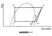
- the state of the refrigerant circulating in the cycle changes as shown in the Mollier diagram of FIG. Specifically, the flow of the high-pressure refrigerant (point a in FIG. 3) discharged from the compressor 11 is branched at the first branch portion 13a. Then, one of the branched refrigerants flows into the indoor condenser 12.
- the refrigerant that has flowed into the indoor condenser 12 exchanges heat with the blown air that has been blown from the blower 32 and passed through the indoor evaporator 20 to dissipate heat (point a ⁇ b in FIG. 3). Thereby, blowing air is heated.
- the refrigerant that has flowed out of the indoor condenser 12 is reduced in pressure until it flows into the heating expansion valve 14 and becomes a low-pressure refrigerant, as in the heating operation mode (point b ⁇ point c in FIG. 3).
- the low-pressure refrigerant decompressed by the heating expansion valve 14 flows into the outdoor heat exchanger 15 and absorbs heat from the outside air blown from the blower fan 15a to evaporate. Furthermore, the refrigerant that has flowed out of the outdoor heat exchanger 15 flows into the accumulator 19 and is separated into gas and liquid (point c ⁇ point d in FIG. 3).
- the other refrigerant (a part of the refrigerant discharged from the compressor 11) branched by the first branch portion 13a flows into the nozzle portion 21a of the ejector 21 and is isentropically decompressed. Are injected (point a ⁇ point e in FIG. 3). And the gaseous-phase refrigerant
- coolant (d point of FIG. 3) isolate
- the refrigerant injected from the nozzle portion 21a and the suction refrigerant sucked from the refrigerant suction port 21d flow into the diffuser portion 21f (point e ⁇ f, point d ⁇ f in FIG. 3).
- the velocity energy of the mixed refrigerant is converted into pressure energy by expanding the refrigerant passage area.
- the vehicle interior can be heated by blowing the air blown by the indoor condenser 12 into the vehicle interior.
- the on-off valve 22 for the nozzle portion is opened and the refrigeration cycle apparatus 10 is switched to the boosting refrigerant circuit, so that the suction refrigerant sucked into the compressor 11 is increased by the boosting action of the ejector 21.
- the pressure (point g in FIG. 3) is increased above the refrigerant pressure (point d in FIG. 3) in the accumulator 19 (that is, higher than the refrigerant evaporation pressure in the outdoor heat exchanger 15 functioning as an evaporator), The density of the suction refrigerant can be increased.
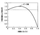
- the increase rate of the radiator-side refrigerant flow rate Gc becomes 1 or more in the range where the flow rate ratio (Gr / Gn) is larger than 0 and smaller than 0.7, and the compressor 11
- the radiator-side refrigerant flow rate Gc flowing out from the first branch portion 13a to the indoor condenser 12 side is increased as compared with the case where the entire flow rate of the refrigerant discharged from the refrigerant flows out to the indoor condenser 12 side.
- the pressure reduction characteristic (flow rate characteristic) of the nozzle portion 21a of the ejector 21 is set so that the flow rate ratio (Gr / Gn) satisfies the above formula F1 in the strong heating operation mode. ) Has been determined. Therefore, at the time of the strong heating operation mode, the radiator-side refrigerant flow rate Gc can be reliably increased, and the heating capacity in the indoor condenser 12 can be reliably suppressed from decreasing.
- the refrigerant discharge capacity (specifically, As the rotational speed of the compressor 11 is increased, the refrigerant evaporation temperature in the outdoor heat exchanger 15 that functions as an evaporator also decreases.
- the refrigerant circuit in the heating operation mode is switched to the refrigerant circuit in the strong heating operation mode (that is, By switching from the non-pressurizing refrigerant circuit to the boosting refrigerant circuit), it is possible to easily control to switch to the refrigerant circuit in the strong heating operation mode at the time of an operating condition in which the refrigerant evaporation temperature in the outdoor heat exchanger 15 decreases to an extremely low temperature. Can be realized.
- the vehicle air conditioner 1 is activated by switching from the refrigerant circuit in the heating operation mode to the refrigerant circuit in the strong heating operation mode. Even when the heat load of the refrigeration cycle apparatus 10 increases, as in the case of performing quick heating sometimes, the radiator-side refrigerant flow rate Gc can be increased to improve the heating capacity of the blown air in the indoor condenser 12. it can.
- a nozzle part opening / closing valve 22 disposed on the upstream side of the refrigerant flow of the nozzle part 21a is employed as an opening / closing apparatus for opening and closing the refrigerant flow path of the refrigerant flowing through the nozzle part 21a. Therefore, the refrigerant circuit switching unit can be configured very easily.
- the accumulator 19 as a gas-liquid separator is provided, and the refrigerant suction port 21d of the ejector 21 is connected to the gas-phase refrigerant outlet of the accumulator 19, so that the refrigerant of the ejector 21 Liquid compression of the compressor 11 connected to the downstream side of the flow can be reliably prevented.
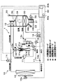
- bypass passage 23 is a refrigerant pipe that guides the gas-phase refrigerant flowing out from the gas-phase refrigerant outlet of the accumulator 19 to the suction port side of the compressor 11 by bypassing the ejector 21.
- the on-off valve 24 is an opening / closing device that opens and closes the bypass passage 23.
- a refrigerant pipe having a relatively large pipe diameter is employed, and the pressure loss caused when the refrigerant flows through the bypass passage 23 is caused by the refrigerant flowing from the gas-phase refrigerant outlet of the accumulator 19 to the ejector 21.
- the pressure loss is smaller than the pressure loss that occurs when the refrigerant flows through the refrigerant flow path leading to the suction port of the compressor 11.
- bypass passage opening / closing valve 24 is constituted by a non-energized opening type (so-called normally open type) electromagnetic valve, and its operation is controlled by a control voltage output from the air conditioning control device 40.
- the nozzle part opening / closing valve 22 and the bypass passage opening / closing valve 24 constitute a refrigerant circuit switching part.
- the air conditioning control device 40 can switch to the boosting refrigerant circuit by opening the nozzle portion opening / closing valve 22 and closing the bypass passage opening / closing valve 24. Further, by switching the nozzle portion opening / closing valve 22 and opening the bypass passage opening / closing valve 24, it is possible to switch to the non-pressurization refrigerant circuit.
- Other configurations are the same as those of the first embodiment.
- the air conditioning control device 40 opens the nozzle portion opening / closing valve 22 and closes the bypass passage opening / closing valve 24. Further, in other operation modes, the refrigerant circuit control unit 40b closes the nozzle opening / closing valve 22 and opens the bypass passage opening / closing valve 24. Other operations are the same as those in the first embodiment.
- each operation mode of the first embodiment is substantially achieved.
- the refrigerant circuit can be switched to the same as that of the first embodiment, and can be operated similarly to the first embodiment. As a result, the same effect as the refrigeration cycle apparatus 10 of the first embodiment can be obtained.
- the gas phase refrigerant flowing out from the gas phase refrigerant outlet of the accumulator 19 is passed through the bypass passage 23.
- the pressure loss generated in the refrigerant circulating in the cycle can be reduced as compared with the refrigerant circuit that leads to the suction port side of the compressor 11 via the ejector 21.
- the power consumption of the compressor 11 can be reduced and the coefficient of performance (COP) of the cycle can be improved.
- the basic configuration of the flow rate adjusting valve 25 is the same as that of the cooling expansion valve 16, and is composed of a variable throttle mechanism with a fully closed function. Further, the flow rate adjusting valve 25 can change the flow rate ratio (Gn / Gr) of the ejector side refrigerant flow rate Gn to the discharged refrigerant flow rate Gr by adjusting the ejector side refrigerant flow rate Gn. Accordingly, the flow rate adjustment valve 25 of the present embodiment constitutes a flow rate ratio adjustment unit.
- the operation of the flow rate adjusting valve 25 is controlled by a control voltage output from the air conditioning control device 40. Therefore, in this embodiment, the structure (hardware and software) which controls the action
- the air conditioning control device 40 fully opens the heating expansion valve 14, sets the cooling expansion valve 16 to a throttling state that exerts a pressure reducing action, and sets the heating on-off valve 18.
- the flow control valve 25 is fully closed. Therefore, in the cooling operation mode, the same cycle as in the first embodiment can be configured and operated in the same manner as in the first embodiment.
- the air conditioning control device 40 sets the heating expansion valve 14 and the cooling expansion valve 16 to a fully open state or throttled state, closes the heating on-off valve 18, and fully closes the flow rate adjustment valve 25. . Therefore, in the dehumidifying and heating operation mode, the same cycle as in the first embodiment can be configured and operated in the same manner as in the first embodiment.
- the strong heating operation mode is not set, and the refrigerant discharge of the compressor 11 is performed when the auto switch is turned on (ON) and the cooling switch is not turned on.
- the operation in the heating operation mode is executed regardless of the capacity.
- the air conditioning control device 40 brings the heating expansion valve 14 into a throttle state, fully closes the cooling expansion valve 16, and opens the heating on-off valve 18. Further, the air-conditioning control device 40 is configured such that the radiator-side refrigerant flow rate Gc of the refrigerant that actually flows into the indoor condenser 12 is greater than or equal to the radiator-side refrigerant flow rate Gc when the flow rate ratio (Gn / Gr) is 0. The operation of the flow rate adjustment valve 25 is controlled so that the increase rate of the radiator-side refrigerant flow rate Gc becomes 1 or more.
- the flow rate ratio (Gn / Gr ) can be adjusted appropriately to increase the radiator-side refrigerant flow rate Gc.
- the flow rate ratio (Gn / Gr) is increased too much, the radiator-side refrigerant flow rate Gc will decrease.
- the increase rate of the radiator-side refrigerant flow rate Gc has a maximum value (peak value) according to the change of the flow rate ratio (Gn / Gr), as shown in FIG. Therefore, the air conditioning control device 40 of the present embodiment controls the operation of the flow rate adjustment valve 25 so that the increasing rate of the radiator-side refrigerant flow rate Gc approaches the maximum value.
- the control map stored in the air conditioning control device 40 in advance is referred to based on the refrigerant discharge capacity of the compressor 11 (specifically, the rotational speed Nc of the compressor 11). Then, the target flow rate ratio set so that the increasing rate of the radiator-side refrigerant flow rate Gc approaches the maximum value is determined. Further, the operation of the flow rate adjustment valve 25 is controlled so that the flow rate ratio (Gn / Gr) approaches the target flow rate ratio.
- the opening degree of the flow rate adjustment valve 25 is adjusted so that the flow rate ratio (Gn / Gr) is about 0.4. And the completely same cycle as the strong heating operation mode of 1st Embodiment can be comprised, and it can be made to operate
- the density of the refrigerant sucked by the compressor 11 can be increased by the pressurizing action of the ejector 21 even when the temperature of the outside air that is the endothermic fluid is decreased. As a result, it can suppress that the heating capability in the indoor condenser 12 falls, and the effect similar to 1st Embodiment can be acquired.
- the operation of the flow rate adjustment valve 25 that is the flow rate adjustment unit is controlled so that the increasing rate of the radiator-side refrigerant flow rate Gc approaches the maximum value. It can suppress effectively that the heating capability in the indoor condenser 12 falls.
- the refrigeration cycle apparatus 10 that can switch between the heating operation mode and the strong heating operation mode has been described.
- the refrigeration cycle apparatus 10 according to the present invention includes at least strong heating. Any device that can execute the operation in the operation mode may be used. Therefore, in the refrigeration cycle apparatus 10 that executes only the operation in the strong heating operation mode, the refrigerant circuit switching unit may be eliminated. Further, in the second embodiment, the nozzle part opening / closing valve 22 may be eliminated and the refrigerant circuit may be switched by the bypass passage opening / closing valve 24.
- an opening / closing device that opens and closes a refrigerant passage that connects the other refrigerant outlet of the first branch portion 13a and the refrigerant inlet of the nozzle portion 21a of the ejector 21 as the refrigerant circuit switching unit.
- a refrigerant circuit switching part is not limited to this.
- any device that can switch between a state in which the refrigerant is injected from the nozzle portion 21a and a state in which the refrigerant is not injected by opening and closing the refrigerant flow path of the refrigerant flowing through the nozzle portion 21a.
- Other types may be adopted.
- an opening / closing device that opens and closes a refrigerant passage formed inside the nozzle portion 21a may be adopted, and the refrigerant circuit switching portion and the ejector 21 may be configured integrally.
- an opening / closing device opening / closing valve 24 for bypass passage
- the refrigerant circuit switching portion is not limited to this.
- this type of switchgear it is arranged on the inlet side of the bypass passage 23 and causes the gas-phase refrigerant flowing out of the accumulator 19 to flow out to the refrigerant suction port 21d side of the ejector 21 and to the bypass passage 23 side. You may employ
- the flow rate ratio adjustment part is not limited to this.
- a variable nozzle capable of adjusting the refrigerant passage area may be adopted as the nozzle portion 21a of the ejector 21, and the flow rate ratio adjusting portion and the ejector 21 may be configured integrally.
- the needle valve 21g that is disposed in the refrigerant passage of the nozzle portion 21a and changes the refrigerant passage area of the throat portion 21c, and the needle valve 21g are displaced in the axial direction of the nozzle portion 21a.
- An ejector 21 having a stepping motor 21h as a driving device to be used can be employed.
- the needle valve 21g can be brought into contact with the inner peripheral wall surface of the refrigerant passage of the nozzle portion 21a to close the refrigerant passage of the nozzle portion 21a, it can be used as the above-described ejector integrated with the refrigerant circuit switching portion. . 8, the needle valve 21g is arranged on the downstream side of the refrigerant flow from the throat portion 21c, and tapers from the downstream side of the refrigerant flow to the throat portion 21c rather than the throat portion 21c. A thing may be adopted.
- the refrigerant circuit control unit 40b may be configured to switch from the non-pressurizing refrigerant circuit to the boosting refrigerant circuit when the outside air temperature Tam becomes equal to or lower than a predetermined reference outside air temperature KTam. Further, the refrigerant circuit control unit 40b, when in the heating operation mode, when the temperature TAV of the blown air (heating target fluid) heated by the indoor condenser 12 (heat radiator) becomes equal to or lower than the target blowing temperature TAO, The non-pressurizing refrigerant circuit may be switched to the boosting refrigerant circuit.
- the present invention may be applied to an air conditioner for a normal vehicle that obtains driving force for driving a vehicle from an internal combustion engine (engine) or a hybrid vehicle that obtains driving force for driving a vehicle from both an internal combustion engine and a driving electric motor. Good. Moreover, you may apply to a stationary air conditioner, a cold storage container, a liquid heating / cooling device, etc., without being limited to vehicles.
- Each component device constituting the refrigeration cycle apparatus 10 is not limited to the one disclosed in the above embodiment.
- the compressor 11 when applied to a vehicle having an internal combustion engine, the compressor 11 is connected via a pulley, a belt, or the like.
- An engine-driven type driven by a rotational driving force transmitted from the vehicle running engine may be employed.
- variable displacement compressor that can adjust the refrigerant discharge capacity by changing the discharge capacity, or adjusting the refrigerant discharge capacity by changing the operating rate of the compressor by intermittently connecting the electromagnetic clutch.
- a fixed capacity compressor can be employed.
- the heating expansion valve 14 is arranged on the refrigerant outlet side of the indoor condenser 12 .
- an orifice, capillary tube, or nozzle is used as a decompression device.
- the switchgear may open the fixed throttle bypass passage, and in the heating operation mode and the strong heating operation mode, the switchgear may close the fixed throttle bypass passage.
- the accumulator 19 is not an indispensable configuration for obtaining the heating capability improvement effect by the refrigeration cycle apparatus 10 of the present invention. Therefore, the accumulator 19 may be eliminated. That is, a gas-liquid two-phase refrigerant or a superheated gas phase refrigerant may be sucked from the refrigerant suction port 21d of the ejector 21.
- the nozzle portion 21a and the body portion 21b of the ejector 21 are formed of metal.
- the material is not limited as long as the function of each constituent member can be exhibited. Therefore, you may form these structural members with resin etc.
- the ejector 21 and the compressor 11 may be integrated so that the refrigerant outlet of the diffuser portion 21f of the ejector 21 and the refrigerant suction port of the compressor 11 are directly connected. Further, the ejector 21 and the accumulator 19 may be integrated so that the refrigerant suction port 21d of the ejector 21 and the gas-phase refrigerant outlet of the accumulator 19 are directly connected.
- R134a or R1234yf can be adopted as the refrigerant, but the refrigerant is not limited to this.
- R600a, R410A, R404A, R32, R1234yfxf, R407C, etc. can be adopted.
Landscapes
- Engineering & Computer Science (AREA)
- Physics & Mathematics (AREA)
- Thermal Sciences (AREA)
- Mechanical Engineering (AREA)
- General Engineering & Computer Science (AREA)
- Life Sciences & Earth Sciences (AREA)
- Sustainable Development (AREA)
- Sustainable Energy (AREA)
- Chemical & Material Sciences (AREA)
- Analytical Chemistry (AREA)
- Power Engineering (AREA)
- Air-Conditioning For Vehicles (AREA)
Priority Applications (3)
| Application Number | Priority Date | Filing Date | Title |
|---|---|---|---|
| DE112014004647.7T DE112014004647T5 (de) | 2013-10-08 | 2014-09-22 | Kälteerzeugungskreis-Einrichtung |
| US15/027,120 US10131203B2 (en) | 2013-10-08 | 2014-09-22 | Refrigeration cycle device |
| CN201480051006.XA CN105556218B (zh) | 2013-10-08 | 2014-09-22 | 制冷循环装置 |
Applications Claiming Priority (2)
| Application Number | Priority Date | Filing Date | Title |
|---|---|---|---|
| JP2013-211076 | 2013-10-08 | ||
| JP2013211076A JP6011507B2 (ja) | 2013-10-08 | 2013-10-08 | 冷凍サイクル装置 |
Publications (1)
| Publication Number | Publication Date |
|---|---|
| WO2015052881A1 true WO2015052881A1 (ja) | 2015-04-16 |
Family
ID=52812717
Family Applications (1)
| Application Number | Title | Priority Date | Filing Date |
|---|---|---|---|
| PCT/JP2014/004845 Ceased WO2015052881A1 (ja) | 2013-10-08 | 2014-09-22 | 冷凍サイクル装置 |
Country Status (5)
| Country | Link |
|---|---|
| US (1) | US10131203B2 (enExample) |
| JP (1) | JP6011507B2 (enExample) |
| CN (1) | CN105556218B (enExample) |
| DE (1) | DE112014004647T5 (enExample) |
| WO (1) | WO2015052881A1 (enExample) |
Cited By (1)
| Publication number | Priority date | Publication date | Assignee | Title |
|---|---|---|---|---|
| EP3524904A1 (en) * | 2018-02-06 | 2019-08-14 | Carrier Corporation | Hot gas bypass energy recovery |
Families Citing this family (18)
| Publication number | Priority date | Publication date | Assignee | Title |
|---|---|---|---|---|
| JP5240332B2 (ja) * | 2011-09-01 | 2013-07-17 | ダイキン工業株式会社 | 冷凍装置 |
| JP6088753B2 (ja) * | 2012-06-13 | 2017-03-01 | サンデンホールディングス株式会社 | 車両用空気調和装置 |
| EP3032192B1 (en) * | 2014-12-09 | 2020-07-29 | Danfoss A/S | A method for controlling a valve arrangement in a vapour compression system |
| US10816245B2 (en) | 2015-08-14 | 2020-10-27 | Danfoss A/S | Vapour compression system with at least two evaporator groups |
| BR112018007382B1 (pt) | 2015-10-20 | 2023-03-21 | Danfoss A/S | Método para controlar um sistema de compressão a vapor com um ponto de ajuste de pressão de receptor variável |
| WO2017067860A1 (en) | 2015-10-20 | 2017-04-27 | Danfoss A/S | A method for controlling a vapour compression system in ejector mode for a prolonged time |
| US10556484B2 (en) * | 2015-10-28 | 2020-02-11 | Ford Global Technologies, Llc | Vehicle climate control valve and operating method |
| JP2017219262A (ja) * | 2016-06-08 | 2017-12-14 | 株式会社デンソー | エジェクタ式冷凍サイクル装置 |
| JP6547781B2 (ja) * | 2016-06-16 | 2019-07-24 | 株式会社デンソー | 冷凍サイクル装置 |
| WO2018080150A1 (en) * | 2016-10-25 | 2018-05-03 | Samsung Electronics Co., Ltd. | Air conditioner |
| US11105544B2 (en) * | 2016-11-07 | 2021-08-31 | Trane International Inc. | Variable orifice for a chiller |
| US10254015B2 (en) * | 2017-02-28 | 2019-04-09 | Thermo King Corporation | Multi-zone transport refrigeration system with an ejector system |
| JP7028079B2 (ja) * | 2018-06-22 | 2022-03-02 | 株式会社デンソー | 冷凍サイクル装置 |
| JP7099899B2 (ja) * | 2018-07-25 | 2022-07-12 | 三菱重工サーマルシステムズ株式会社 | 車両用空調装置 |
| DK180146B1 (en) | 2018-10-15 | 2020-06-25 | Danfoss As Intellectual Property | Heat exchanger plate with strenghened diagonal area |
| CN113883738B (zh) * | 2021-09-29 | 2022-11-11 | 浙江工业大学 | 一种新型太阳能喷射-压缩制冷系统 |
| DE102022130636A1 (de) * | 2022-11-18 | 2024-05-23 | Denso Corporation | Kältemittelkreislauf, insbesondere für ein Kraftfahrzeug und Verfahren zum Betreiben eines solchen |
| WO2025018117A1 (ja) * | 2023-07-20 | 2025-01-23 | 株式会社デンソー | ヒートポンプサイクル装置 |
Citations (8)
| Publication number | Priority date | Publication date | Assignee | Title |
|---|---|---|---|---|
| US2513361A (en) * | 1944-11-01 | 1950-07-04 | Specialties Dev Corp | Method and system for producing low-temperature refrigeration |
| GB660771A (en) * | 1949-02-03 | 1951-11-14 | Svenska Turbinfab Ab | Improvements in refrigerating machinery |
| US2887857A (en) * | 1955-06-28 | 1959-05-26 | Hugh J Scullen | Jet pumps in refrigeration system |
| JPS59225259A (ja) * | 1983-06-02 | 1984-12-18 | 三洋電機株式会社 | 冷凍装置 |
| US6698221B1 (en) * | 2003-01-03 | 2004-03-02 | Kyung Kon You | Refrigerating system |
| JP2008190769A (ja) * | 2007-02-05 | 2008-08-21 | Denso Corp | エジェクタ式冷凍サイクル |
| JP2012117760A (ja) * | 2010-12-01 | 2012-06-21 | Tokyo Electric Power Co Inc:The | ヒートポンプ及び熱供給システム |
| JP2013108632A (ja) * | 2011-11-17 | 2013-06-06 | Denso Corp | エジェクタ式冷凍サイクル |
Family Cites Families (9)
| Publication number | Priority date | Publication date | Assignee | Title |
|---|---|---|---|---|
| US5704219A (en) | 1995-08-01 | 1998-01-06 | Nippondenso Co., Ltd. | Air conditioning apparatus |
| JP3257361B2 (ja) | 1995-08-01 | 2002-02-18 | 株式会社デンソー | 車両用空調装置 |
| JP2004257694A (ja) * | 2003-02-27 | 2004-09-16 | Denso Corp | 蒸気圧縮式冷凍機 |
| CN101952670B (zh) * | 2008-04-18 | 2013-04-17 | 株式会社电装 | 喷射器式制冷循环装置 |
| JP5108606B2 (ja) | 2008-04-23 | 2012-12-26 | カルソニックカンセイ株式会社 | 空気調和システム |
| DE102012205200B4 (de) | 2011-04-04 | 2020-06-18 | Denso Corporation | Kältemittelkreislaufvorrichtung |
| JP5321647B2 (ja) | 2011-06-15 | 2013-10-23 | 株式会社デンソー | 冷凍サイクル装置 |
| CN102734989B (zh) | 2011-04-08 | 2014-05-07 | 约克广州空调冷冻设备有限公司 | 一种快速排出气液分离器中积存的液体的热泵空调系统及方法 |
| JP6102552B2 (ja) | 2012-11-16 | 2017-03-29 | 株式会社デンソー | 冷凍サイクル装置 |
-
2013
- 2013-10-08 JP JP2013211076A patent/JP6011507B2/ja not_active Expired - Fee Related
-
2014
- 2014-09-22 US US15/027,120 patent/US10131203B2/en not_active Expired - Fee Related
- 2014-09-22 CN CN201480051006.XA patent/CN105556218B/zh not_active Expired - Fee Related
- 2014-09-22 DE DE112014004647.7T patent/DE112014004647T5/de not_active Withdrawn
- 2014-09-22 WO PCT/JP2014/004845 patent/WO2015052881A1/ja not_active Ceased
Patent Citations (8)
| Publication number | Priority date | Publication date | Assignee | Title |
|---|---|---|---|---|
| US2513361A (en) * | 1944-11-01 | 1950-07-04 | Specialties Dev Corp | Method and system for producing low-temperature refrigeration |
| GB660771A (en) * | 1949-02-03 | 1951-11-14 | Svenska Turbinfab Ab | Improvements in refrigerating machinery |
| US2887857A (en) * | 1955-06-28 | 1959-05-26 | Hugh J Scullen | Jet pumps in refrigeration system |
| JPS59225259A (ja) * | 1983-06-02 | 1984-12-18 | 三洋電機株式会社 | 冷凍装置 |
| US6698221B1 (en) * | 2003-01-03 | 2004-03-02 | Kyung Kon You | Refrigerating system |
| JP2008190769A (ja) * | 2007-02-05 | 2008-08-21 | Denso Corp | エジェクタ式冷凍サイクル |
| JP2012117760A (ja) * | 2010-12-01 | 2012-06-21 | Tokyo Electric Power Co Inc:The | ヒートポンプ及び熱供給システム |
| JP2013108632A (ja) * | 2011-11-17 | 2013-06-06 | Denso Corp | エジェクタ式冷凍サイクル |
Cited By (2)
| Publication number | Priority date | Publication date | Assignee | Title |
|---|---|---|---|---|
| EP3524904A1 (en) * | 2018-02-06 | 2019-08-14 | Carrier Corporation | Hot gas bypass energy recovery |
| US10941966B2 (en) | 2018-02-06 | 2021-03-09 | Carrier Corporation | Hot gas bypass energy recovery |
Also Published As
| Publication number | Publication date |
|---|---|
| DE112014004647T5 (de) | 2016-07-21 |
| CN105556218A (zh) | 2016-05-04 |
| US20160280041A1 (en) | 2016-09-29 |
| JP6011507B2 (ja) | 2016-10-19 |
| CN105556218B (zh) | 2017-06-20 |
| JP2015075268A (ja) | 2015-04-20 |
| US10131203B2 (en) | 2018-11-20 |
Similar Documents
| Publication | Publication Date | Title |
|---|---|---|
| JP6011507B2 (ja) | 冷凍サイクル装置 | |
| JP5967022B2 (ja) | 冷凍サイクル装置 | |
| JP6277888B2 (ja) | 冷凍サイクル装置 | |
| US9771954B2 (en) | Ejector | |
| JP6528733B2 (ja) | エジェクタ式冷凍サイクル | |
| JP6102552B2 (ja) | 冷凍サイクル装置 | |
| JP2018118540A (ja) | 冷凍サイクル装置 | |
| JP2020029983A (ja) | 冷凍サイクル装置 | |
| US10442274B2 (en) | Ejector refrigeration cycle device and low outside temperature operation thereof | |
| JP6642297B2 (ja) | エジェクタ式冷凍サイクル | |
| JP6561922B2 (ja) | 統合弁 | |
| JP6973539B2 (ja) | 冷凍サイクル装置 | |
| WO2019017169A1 (ja) | エジェクタモジュール | |
| JP6720932B2 (ja) | エジェクタ式冷凍サイクル | |
| JP6669033B2 (ja) | エジェクタ式冷凍サイクル | |
| JP6582843B2 (ja) | 冷凍サイクル装置 | |
| WO2018003352A1 (ja) | 冷凍サイクル装置 | |
| WO2018088033A1 (ja) | 冷凍サイクル装置 | |
| JP2018063071A (ja) | 膨張弁 |
Legal Events
| Date | Code | Title | Description |
|---|---|---|---|
| WWE | Wipo information: entry into national phase |
Ref document number: 201480051006.X Country of ref document: CN |
|
| 121 | Ep: the epo has been informed by wipo that ep was designated in this application |
Ref document number: 14853125 Country of ref document: EP Kind code of ref document: A1 |
|
| WWE | Wipo information: entry into national phase |
Ref document number: 15027120 Country of ref document: US |
|
| WWE | Wipo information: entry into national phase |
Ref document number: 112014004647 Country of ref document: DE Ref document number: 1120140046477 Country of ref document: DE |
|
| 122 | Ep: pct application non-entry in european phase |
Ref document number: 14853125 Country of ref document: EP Kind code of ref document: A1 |