WO2015046481A1 - 液滴材料吐出装置、同液体材料吐出装置を備える塗布装置および同塗布装置を用いた塗布方法 - Google Patents
液滴材料吐出装置、同液体材料吐出装置を備える塗布装置および同塗布装置を用いた塗布方法 Download PDFInfo
- Publication number
- WO2015046481A1 WO2015046481A1 PCT/JP2014/075789 JP2014075789W WO2015046481A1 WO 2015046481 A1 WO2015046481 A1 WO 2015046481A1 JP 2014075789 W JP2014075789 W JP 2014075789W WO 2015046481 A1 WO2015046481 A1 WO 2015046481A1
- Authority
- WO
- WIPO (PCT)
- Prior art keywords
- plunger
- liquid material
- unit
- valve
- discharge device
- Prior art date
Links
Images


Classifications
-
- B—PERFORMING OPERATIONS; TRANSPORTING
- B05—SPRAYING OR ATOMISING IN GENERAL; APPLYING FLUENT MATERIALS TO SURFACES, IN GENERAL
- B05C—APPARATUS FOR APPLYING FLUENT MATERIALS TO SURFACES, IN GENERAL
- B05C5/00—Apparatus in which liquid or other fluent material is projected, poured or allowed to flow on to the surface of the work
- B05C5/02—Apparatus in which liquid or other fluent material is projected, poured or allowed to flow on to the surface of the work the liquid or other fluent material being discharged through an outlet orifice by pressure, e.g. from an outlet device in contact or almost in contact, with the work
- B05C5/027—Coating heads with several outlets, e.g. aligned transversally to the moving direction of a web to be coated
- B05C5/0275—Coating heads with several outlets, e.g. aligned transversally to the moving direction of a web to be coated flow controlled, e.g. by a valve
-
- B—PERFORMING OPERATIONS; TRANSPORTING
- B05—SPRAYING OR ATOMISING IN GENERAL; APPLYING FLUENT MATERIALS TO SURFACES, IN GENERAL
- B05C—APPARATUS FOR APPLYING FLUENT MATERIALS TO SURFACES, IN GENERAL
- B05C11/00—Component parts, details or accessories not specifically provided for in groups B05C1/00 - B05C9/00
- B05C11/10—Storage, supply or control of liquid or other fluent material; Recovery of excess liquid or other fluent material
- B05C11/1002—Means for controlling supply, i.e. flow or pressure, of liquid or other fluent material to the applying apparatus, e.g. valves
-
- B—PERFORMING OPERATIONS; TRANSPORTING
- B05—SPRAYING OR ATOMISING IN GENERAL; APPLYING FLUENT MATERIALS TO SURFACES, IN GENERAL
- B05C—APPARATUS FOR APPLYING FLUENT MATERIALS TO SURFACES, IN GENERAL
- B05C5/00—Apparatus in which liquid or other fluent material is projected, poured or allowed to flow on to the surface of the work
- B05C5/02—Apparatus in which liquid or other fluent material is projected, poured or allowed to flow on to the surface of the work the liquid or other fluent material being discharged through an outlet orifice by pressure, e.g. from an outlet device in contact or almost in contact, with the work
- B05C5/027—Coating heads with several outlets, e.g. aligned transversally to the moving direction of a web to be coated
- B05C5/0275—Coating heads with several outlets, e.g. aligned transversally to the moving direction of a web to be coated flow controlled, e.g. by a valve
- B05C5/0279—Coating heads with several outlets, e.g. aligned transversally to the moving direction of a web to be coated flow controlled, e.g. by a valve independently, e.g. individually, flow controlled
-
- B—PERFORMING OPERATIONS; TRANSPORTING
- B05—SPRAYING OR ATOMISING IN GENERAL; APPLYING FLUENT MATERIALS TO SURFACES, IN GENERAL
- B05D—PROCESSES FOR APPLYING FLUENT MATERIALS TO SURFACES, IN GENERAL
- B05D1/00—Processes for applying liquids or other fluent materials
- B05D1/26—Processes for applying liquids or other fluent materials performed by applying the liquid or other fluent material from an outlet device in contact with, or almost in contact with, the surface
Definitions
- the present invention relates to a discharge device capable of changing the interval and the number of discharge ports according to applications and a coating method using the same.
- Patent Document 1 discloses a discharge device that moves a plunger backward to suck a liquid material into a measurement hole, and then moves the plunger forward to push the liquid material in the measurement hole toward a discharge port to discharge the liquid material.
- Patent Document 2 discloses a discharge device having a plurality of plungers.
- a liquid material discharge device including a plurality of metering units disposed adjacent to each other, wherein each of the metering units includes a plunger and a nozzle, and the plurality of plungers advance and retreat simultaneously.
- each plunger is fixed to the slider of the plunger driving unit by a screw.
- An object of this invention is to provide the discharge apparatus which can make the space
- the present invention related to the liquid material discharge device includes a plunger unit having three or more plungers, a plunger driving unit for reciprocating the plunger unit, and three or more measuring holes through which each plunger is inserted, A valve unit having a discharge port and a liquid material supply path communicating with the measurement hole, a first position communicating the measurement hole and the liquid material supply path, and a second position communicating the measurement hole and the discharge port; A valve unit driving unit that switches between the first and second positions of the valve unit, and a plunger driving unit, a device body on which the valve unit and the valve driving unit are arranged, and the plunger unit holds the plunger in alignment.
- the plunger holder is detachably attached to the plunger drive unit.
- the plunger unit aligns and holds the plunger at a second interval different from the first interval, and the first plunger unit that aligns and holds the plunger at a first interval.
- 2 plunger units, and one selected plunger unit may be detachably attached.
- the plunger unit aligns and holds a first plunger unit that holds three or more plungers in alignment and a second number that holds a larger number of plungers than the first plunger unit.
- the selected plunger unit may be detachably attached.
- the plunger unit has a plunger holder that aligns and holds the plunger in an arrangement of n rows ⁇ m columns (where n and m are integers of 2 or more).
- the valve unit includes a recess that communicates the measurement hole and the liquid material supply path at the first position, and a discharge path that communicates the measurement hole and the discharge port at the second position.
- the valve member and a holding member that slidably holds the valve member may be provided, and the valve member may further include a leakage prevention groove surrounding the recess and the discharge path. Good.
- the holding member has one liquid material supply path that communicates with a liquid material supply source, and more preferably, the valve unit communicates with the metering hole in the second position.
- a nozzle member having a discharge port, and the valve member is slidably disposed between the nozzle member and the holding member.
- the device main body includes a valve unit support mechanism and a locking tool for slidably supporting the valve member, and releasing the fixation by the locking tool to remove the valve unit from the device main body. It can be pulled out and removed.
- the present invention relating to a coating apparatus includes any one of the above-described liquid material ejection apparatuses, a work table on which an object to be coated is placed, an XYZ direction movement apparatus that relatively moves the liquid quantitative ejection apparatus and the work table, and XYZ. And a control unit that controls the operation of the direction moving device.
- the present invention relating to a coating method is a coating method using the above-described coating apparatus, and is a coating method for simultaneously coating a plurality of identically shaped patterns provided at equal intervals on a single workpiece.
- ADVANTAGE OF THE INVENTION it becomes possible to provide the discharge apparatus which can make the space
- ADVANTAGE OF THE INVENTION it becomes possible to provide the application
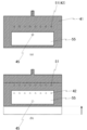
- (A) is a front view of a plunger holder, (b) is the top view.
- (A) is a front view of the modification of a plunger holder, (b) is the top view.
- FIG. 4C is a side sectional view showing the state
- FIG. 4C is a side sectional view showing a state where the valve unit takes the second position and the plunger is located above
- FIG. 4D shows the plan where the valve unit takes the second position. It is side surface sectional drawing which shows the state which a jar is located in the lowest end.
- the valve member which concerns on the example of 1st Embodiment WHEREIN (a) is a horizontal sectional view explaining the state in a 2nd position, (b) is a horizontal sectional view explaining the state in a 1st position. It is a front view of the coating device carrying the discharge device which concerns on the example of 1st Embodiment. It is a perspective view which shows the state which decomposed
- FIG. 1 It is a front view of the discharge device in the state which shows the state where the plunger unit was removed from the raising / lowering body. It is a front view of the discharge device with the valve unit cover open. It is a front view of a discharge device in the state where a valve unit was removed from an elevator.
- (A) is a plunger holder which concerns on 2nd Embodiment
- (b) is a disassembled perspective view of the valve unit which concerns on 2nd Embodiment.
- (a) is a horizontal sectional view explaining the state in a 2nd position
- (b) is a horizontal sectional view explaining the state in a 1st position.
- (a) is a horizontal sectional view explaining the state in the 2nd position
- (b) is a horizontal sectional view explaining the state in the 1st position.
- (a) is a horizontal sectional view explaining the state in the 2nd position
- (b) is a horizontal sectional view explaining the state in the 1st position.
- the liquid material supplied to the liquid material supply port is sucked into the measuring hole by the backward movement of three or more plungers, and the plunger moves forward after the flow path switching operation of the valve. It is an apparatus that discharges simultaneously from three or more discharge ports.
- the liquid material is supplied from only one location of the liquid material supply port, but the liquid material supplied in the discharge unit is distributed to three or more measurement holes, and is supplied from each of the same number of discharge ports as the measurement holes. It is possible to discharge simultaneously.
- the discharge device of the present invention includes three or more plungers, and these plungers are attached to a plunger holder that defines an arrangement interval and are unitized, so that handling is easy.
- the discharge device of the present invention is suitable for applying a plurality of identically shaped patterns provided at equal intervals on one work at the same time, for example, applying a conductive paste on a semiconductor work frame, or a phosphor on an LED work frame. Suitable for potting. That is, the present invention also provides a coating apparatus and a coating method for simultaneously coating a plurality of the same shape patterns provided at equal intervals on one workpiece.
- the plurality of plungers may be arranged in a single row or a single column, but may be arranged in a plurality of rows or a plurality of columns. That is, n ⁇ m (where n and m are each an integer of 1 or more, and n ⁇ m is 3 or more. Preferably, n ⁇ m is 4 or more, more preferably n ⁇ m is 5 or more)) can be mounted.
- n ⁇ m can be arbitrarily changed, but in general, n and m are both integers of 10 or less, and the value of n ⁇ m is 20 or less.
- discharge apparatus of this invention is demonstrated by the example of an embodiment.
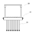
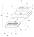
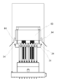
- the discharge device 1 includes a plunger unit 20, a valve unit 40, a plunger driving unit 60, and a valve driving unit 70 as main components.
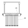
- the plunger unit 20 includes eight plungers 21 for sucking or extruding the liquid material.
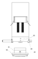
- the eight plungers 21 are arranged at equal intervals in the row direction, and are inserted into the plunger holder 31.
- the plunger holder 31 is connected to an elevating body 63, and a back portion of the elevating body 63 is fixed to a slide base 62.
- the slide base 62 is connected to a pair of slide rails (not shown) at the back of the pair of openings 65 disposed on the front surface of the upright apparatus body 2, and the plunger 21 moves up and down together with the slide base 62. do.
- the valve unit 40 switches the communication of the flow path between when the liquid material is sucked and when it is discharged, sucks the liquid material into the discharge device by the backward movement of the plunger, and discharges it by the forward movement of the plunger.
- the plunger drive unit 60 includes a drive source such as a motor and an actuator for operating the plunger unit 20.
- the valve drive unit 70 includes a drive source such as a motor or an actuator for operating the valve unit 40.
- the plunger unit 20 includes a plurality of plungers 21 and a plunger holder 31.
- Each plunger 21 is inserted into a plurality of corresponding metering holes 42 in a one-to-one correspondence, sucking the liquid material into the metering hole by the backward movement of the plunger, and liquid material in the metering hole by the forward movement of the plunger. Is discharged.
- the plunger holder 31 holds a specified number of plungers 21 at a predetermined interval.
- Plural types of plunger unit 20 are preferably prepared. That is, it is preferable to prepare a plurality of plunger units 20 having different pitches and / or different numbers of plungers 21.
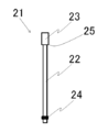
- the plunger 21 is constituted by a plunger rod 22 having a plunger tail 23 at the rear end.
- the plunger rod 22 is a cylindrical long member
- a plunger tail 23 is a cylindrical member having a larger diameter than the plunger rod 22.
- An annular seal 24 is provided at the distal end portion of the plunger rod 22.
- the seal 24 may not be provided.
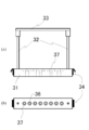
- the plunger holder 31 has two struts 32 fixed in the vicinity of both sides thereof. The upper ends of the two columns 32 are connected by a handle 33. On both side surfaces of the plunger holder 31, locking claws 34 for attaching to the elevating body 63 are provided.
- the locking claw 34 is, for example, a Draw Latch claw, and engages with a patching lock body which is a pair of locking tools 64 provided on the side surface of the elevating body 63.
- the patch lock is merely an example, and it goes without saying that it can be connected and fixed using other detachable connecting means.
- Plunger insertion holes (36, 37) are provided in the plunger holder 31 in the vertical direction as many as the number of plungers 21 to be held.
- the plunger insertion hole includes a small-diameter hole 36 positioned below and a large-diameter hole 37 positioned above.
- the large diameter hole 37 has substantially the same diameter as the plunger tail 23, and the shoulder 25 of the plunger tail 23 abuts on the bottom of the large diameter hole 37.
- the plunger 21 is fixed by sandwiching the plunger tail 23 with the lower surface.
- the small diameter hole 36 is formed to have a larger diameter than the diameter of the plunger rod 22.
- the diameter is larger than that of the seal 24.
- the shoulder 25 of the plunger tail 23 may be brought into contact with the upper surface of the plunger holder 31 from above without providing the large-diameter hole 37.
- a small-diameter hole 36 having a smaller diameter than the plunger tail 23 penetrating the plunger holder 31 is formed, and the plunger rod 22 is inserted from above the small-diameter hole 36, and the plunger tail is formed on the upper surface of the plunger holder 31.
- the plunger 21 is fixed by abutting the shoulder portions 25 of 23.
- FIG. 6A is a front view of a modified example of the plunger holder 31, and FIG. 6B is a plan view thereof.
- the plunger holder 31 shown in FIG. 6 is provided with introduction grooves 35 that are more than the number of plungers 21 to be held.
- the introduction groove 35 is open to the front side surface of the plunger holder 31, and a small diameter hole 36 located below and a large diameter hole 37 located above are provided in the rear part of the introduction groove 35. It has been.
- the width of the introduction groove 35 is slightly wider than the plunger rod 22. Note that the width of the introduction groove 35 need not be wider than that of the seal 24.
- the width of the small diameter hole 36 is equal to the width of the introduction groove 35, and the rear portion of the introduction groove 35 substantially constitutes the small diameter hole 36.
- FIG. 7 shows a side view of the plunger holder 31 shown in FIG. 6 with the plunger 21 attached thereto.
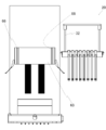
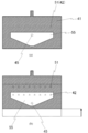
- FIG. 8 is a perspective view illustrating the configuration of the valve unit 40.
- the valve unit 40 includes a measuring member 41, a holding member 48, and a valve member 50 as main components.
- the measuring member 41 includes as many measuring holes 42 as the number of plungers 21. Each measuring hole 42 has the same length. It is preferable to prepare a plurality of types of valve units 40 so that a plurality of types of plunger units 20 can be received. That is, it is preferable to prepare a plurality of valve units 40 having different pitches and / or different numbers of measuring holes 42.
- the measurement hole 42 is a through-hole penetrating the measurement member 41 and the holding member 48, and has a measurement hole upper opening 43 on the upper surface of the measurement member 41 and a measurement hole lower opening 44 on the lower surface of the holding member 48.
- the central pitch of the measuring holes 42 is the same as the central pitch of the small diameter holes 36 provided in the plunger holder 31. That is, the intervals between the measurement holes 42 are the same as the intervals between the plungers 21 inserted into the plunger holder 31.
- a desired amount of liquid material is sucked into the measuring hole 42 by the backward movement of the plunger 21 inserted through the upper opening 43 of the measuring hole. That is, the measuring hole 42 sucks or discharges the liquid material in cooperation with the plunger 21 that moves forward or backward.
- a single liquid material supply path 45 is formed in the measuring member 41 and the holding member 48.
- the liquid material supply path 45 is a through-hole penetrating the measuring member 41 and the holding member 48, and has a supply path inlet 46 on the upper surface of the measuring member 41 and a supply path outlet 47 on the lower surface of the holding member 48.
- a plate-like holding member 48 is provided below the measuring member 41.
- the measuring member 41 and the holding member 48 may be manufactured separately and connected, or may be manufactured integrally.
- the holding member 48 has a pair of holding portions 49 provided symmetrically on the left and right sides of the lower surface thereof.
- the holding portion 49 has a L-shaped cross section in the short direction, and side convex portions 59 on both side surfaces of the valve member 50 are slid into the L shape. That is, the valve member 50 is slidably held by causing the pair of side surface protrusions 59 to enter the pair of holding portions 49 provided on the lower surface of the holding member 48.
- FIG. 9A is a perspective view of the valve member 50
- FIG. 9B is a horizontal sectional view of the valve member 50
- the valve member 50 has a plurality of discharge paths 51 on the back side of the upper surface, and a recess 55 on the front side of the upper surface.
- the discharge passage 51 is a through hole extending from the upper surface to the lower surface of the valve member 50.
- the upper surface of the valve member 50 becomes the discharge passage inlet 52 of the discharge passage 51, and the lower surface of the valve member 50 becomes the discharge port 53.
- the flow path diameter is tapered, and a nozzle 54 having a discharge port 53 at the lower end is formed.
- valve members 50 having discharge ports 53 with different diameters. Since the valve member 50 can be attached and detached by sliding it with respect to the measuring member 41, the replacement is easy.
- the center pitch of the discharge passages 51 equal to the number of the measurement holes 42 is the same as the center pitch of the measurement holes 42. That is, the pitch at the center of the small diameter hole 36 provided in the plunger holder 31, the pitch at the center of the measuring hole 42, and the pitch at the center of the discharge passage 51 are all the same.
- the recess 55 is a rectangular recess formed by drilling from the upper surface of the valve member 50. As will be described later, the recess 55 constitutes a supply channel that communicates the liquid material supply channel 45 with all the measurement holes 42.
- the shape of the recess 55 is not limited to the illustrated rectangular shape, and may be any shape such as a substantially triangular shape, a substantially trapezoidal shape, a substantially pentagonal shape, and a substantially elliptical shape as viewed from above, and may be a branch path.
- the width of the concave portion 55 in the left-right direction is longer than the length connecting the outer extensions of the discharge passages 51 at the left and right ends.
- the back surface of the valve member 50 is formed with a back surface convex portion 58 that is narrower than the width of the back surface in the left-right direction.
- the back convex part 58 is a rectangular parallelepiped member, and the connection tool 72 of the valve drive part 70 is connected.
- the valve drive unit 70 reciprocates the connector 72 in the horizontal direction, thereby reciprocating the valve member 50 in the horizontal direction relative to the measuring member 41. Accordingly, the valve member 50 has a first position where the liquid material supply path 45 and the measurement hole 42 communicate with each other, and a second position where the measurement hole 42 of the measurement member 41 and the discharge path 51 of the valve member 50 communicate with each other. And take.
- FIG. 10A is a perspective view for explaining a modification of the valve member 50
- FIG. 10B is a horizontal sectional view.
- an annular leakage prevention groove 56 is provided so as to surround all the discharge paths 51 and the recesses 55. Therefore, even if the liquid material leaks from the discharge path 51 or the recess 55, the liquid material leaked into the leakage prevention groove 56 is caught.
- the valve member 50 may be constituted by two plate-like members to be stacked. In this configuration, the lower plate member (nozzle member) having the discharge port 53 is not horizontally moved when the first and second positions are switched, and only the upper plate member (valve member) is the measuring member 41. And the lower plate-like member (nozzle member) are slid while being slid.
- Such a configuration has an advantage that problems such as liquid dripping from the discharge port 53 do not easily occur because the discharge port 53 does not move horizontally.
- the plunger drive unit 60 includes a drive device A61, a slide base 62, and an elevating body 63.
- the drive device A61 is, for example, a motor, and is a drive source that reciprocates the slide base 62 in the extending direction of the measuring hole 42.
- a lift body 63 is connected to the slide base 62.
- the slide base 62 is movable along a pair of elongated openings 65 extending in the vertical direction.
- Locking tools 64 that engage with the locking claws 34 of the plunger holder 31 are provided on the left and right side surfaces of the elevating body 63.
- the plunger holder 31 can be detachably connected and fixed to the lifting body 63 by engaging the locking tool 64 of the lifting body 63 with the locking claw 34 on the side surface of the plunger holder 31.
- the valve drive unit 70 includes an arm 71, a connection tool 72, and a drive device 73.
- a connecting tool 72 is connected to one end of the arm 71, and a driving device 73 is connected to the other end.
- the connection tool 72 Via the connection tool 72, the rear surface projection 58 and the arm 71 of the valve member 50 are detachably connected and fixed. Thereby, the movement of the arm 71 by the driving device 73 is transmitted to the valve member 50 via the connector 72, and the valve member 50 reciprocally slides relative to the measuring member 41.
- the drive device 73 is an air actuator, for example, and moves the arm 71 extending in the horizontal direction to move forward or backward relative to the valve unit.
- valve unit 40 When the driving device 73 moves the arm 71 backward, the valve unit 40 takes a first position where the liquid material supply path 45 and the measuring hole 42 communicate with each other, and when the arm 71 moves forward, the valve unit 40 moves the measuring hole. A second position is established where 42 and the discharge port 53 communicate with each other. As described above, the valve drive unit 70 performs the valve switching operation of the valve unit 40.
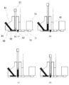
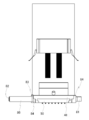
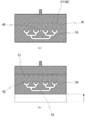
- FIG. 11A shows a state where the valve unit 40 takes the first position and the plunger 21 is located at the lowermost end.
- the measurement hole 42 and the liquid material supply path 45 communicate with each other via the recess 55, and the measurement hole 42 and the discharge port 53 are blocked.
- the discharge path 51 is filled with a liquid material, but is not in communication with the measuring hole 42.
- FIG. 11B shows a state in which the valve unit 40 takes the first position and the plunger 21 is positioned upward. That is, the plunger 21 is moved upward from the state of FIG. 11A and the liquid material is supplied to the measuring hole 42.
- the upper position of the plunger 21 is variable, and the amount of liquid material sucked into the metering hole 42 can be controlled by controlling the driving device A61 to control the amount by which the plunger 21 is raised. That is, a desired amount of liquid material can be sucked into the measuring hole 42.
- FIG. 11C shows a state in which the valve unit 40 takes the second position and the plunger 21 is positioned upward. That is, when the valve member 50 moves forward from the state of FIG. 11B, the measurement hole 42 and the liquid material supply path 45 are blocked, and the measurement hole 42 and the discharge port 53 are communicated.
- the plunger 21 holds the position (height) illustrated in FIG.
- FIG. 11D shows a state in which the valve unit 40 takes the second position and the plunger 21 is located at the lowermost end. That is, the plunger 21 is moved downward from the state of FIG. 11C and the liquid material in the measuring hole 42 is discharged.
- the plunger 21 is moved to the lowermost end to discharge all the liquid material in the measuring hole 42, but the plunger 21 is stopped one or more times before the lowermost end of the measuring hole 42.
- the lowering operation may be repeated to perform discharge. That is, by controlling the driving device A and lowering the plunger 21 intermittently, the liquid material in the measuring hole 42 can be divided into a plurality of droplets and discharged.
- the liquid material discharged at one time from one discharge port 53 is, for example, in the order of ng to mg.
- the valve member 50 is moved backward by the driving device 73 from the state shown in FIG. 11D after the discharge operation is completed, the state returns to the state shown in FIG.
- the liquid material supply path 45 is always in communication with a liquid supply source (not shown), and the liquid material supply path 45 and the recess 55 are always filled with the liquid material.
- FIG. 12A is a horizontal sectional view for explaining a state in which the valve member 50 is in the second position
- FIG. 12B is a horizontal sectional view for explaining a state in which the valve member 50 is in the first position.
- the discharge path 51 and the measurement hole 42 communicate with each other at the second position
- the liquid material in the measurement hole 42 can be discharged.
- the measurement hole 42 and the liquid material supply path 45 are in a positional relationship illustrated by a dotted line at the first position and communicate with each other via the recess 55. It becomes possible to suck.
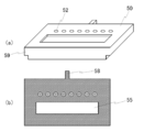
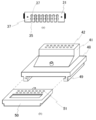
- FIG. 13 is a front view of a coating device 90 on which the discharge device 1 is mounted.
- the coating device 90 includes an X-direction moving device 91 that allows the discharge device 1 to move in the X direction, a Y-direction moving device 92 that allows the table 94 to move in the Y direction, and a Z-direction moving device that holds the apparatus main body 2. 93 and a gantry 95 on which a table 94 is mounted.
- the XYZ direction moving devices (91, 92, 93) include, for example, a combination of an electric motor and a ball screw, a mechanism using a linear motor, and a mechanism for transmitting power by a belt, a chain, or the like.
- a workpiece is placed on the table 94, and the application operation is performed while the discharge device 1 and the table 94 are relatively moved in the XYZ directions.
- FIG. 14 is a perspective view showing a state where the discharge device 1 is disassembled. As shown in FIG. 14, the discharge device 1 can remove the plunger unit 20 and the valve unit 40 from the apparatus main body side. Furthermore, the plunger unit 20 can be disassembled into a plunger holder 31 and a plunger 21, and the valve unit 40 can be disassembled into a measuring member 41 and a valve member 50. 14 shows the plunger holder 31 shown in FIG. 6 and the valve member 50 shown in FIG.
- FIG. 15 is a front view of the discharge device 1 in a state in which the locking claw 34 on the side surface of the plunger holder 31 is removed from the locking tool 64 of the lifting body 63
- FIG. 16 is a state where the plunger unit 20 is removed from the lifting body 63.
- the front view of the discharge apparatus 1 of this is shown.
- the illustrated patch and lock (34, 64) is convenient because it can be connected and disconnected without requiring a special tool such as a driver or a wrench.
- the valve unit 40 is removed by releasing the engagement between the claw 82 of the valve unit cover 80 and the locking tool 81.
- the valve unit cover 80 is a locking tool that fixes the position of the valve unit 40.
- the end of the valve unit cover 80 opposite to the claw 82 is fixed by a hinge 83 and can be rotated.
- the valve unit 40 is supported by a valve unit support mechanism so that it can be pulled out. That is, the valve unit support 84 supports the side protrusions 59 of the holding member 48, and the pin 85 is inserted into a hole provided on the back surface of the measuring member 41, thereby supporting the valve unit 40 so that it can be pulled out. Yes.
- the valve unit 40 can be removed by rotating and opening the valve unit cover 80 and pulling out the measuring member 41 and the valve member 50.
- FIG. 17 shows a front view of the discharge device 1 with the valve unit cover 80 opened
- FIG. 18 shows a front view of the discharge device 1 with the valve unit 40 removed from the elevating body 63.
- the interval and number of discharge ports can be made variable. .
- FIG. 19A is a plunger holder 31 according to the second embodiment
- FIG. 19B is an exploded perspective view of the valve unit 40 according to the second embodiment.
- the plunger holder 31 is provided with 16 large-diameter holes 37 (2 rows ⁇ 8 columns).
- the large-diameter hole 37 has the same configuration as in FIGS.
- the width of the introduction groove 35 is slightly wider than the plunger rod 22.
- the eight introduction grooves 35 are provided at the same pitch.
- the 16 large diameter holes 37 are provided at the same pitch in both the row direction and the column direction.
- the metering member 41 is provided with 16 metering holes 42
- the valve member 50 is provided with 16 discharge passages 51.
- the pitches of the centers of the measurement holes 42, the discharge passages 51, and the large diameter holes 37 are all the same.
- the valve unit 40 has the aforementioned first position and second position. And when it exists in a 1st position, the recessed part 55 will be in the positional relationship which covers the supply hole exit 47 and all the measurement hole lower openings 44, the supply hole exit 47 and all the measurement holes 42 are connected, and 2nd position In this state, all the measurement holes 42 are communicated with the discharge ports 53 through the discharge passage 51.
- the ejection device 1 can be mounted with the plunger 21 of n ⁇ m (where n and m are integers of 1 or more and n ⁇ m is 3 or more). Is possible. By preparing the plunger unit 20 including the plungers with different numbers and / or pitches and the corresponding valve unit 40, it is possible to realize the optimal mounting of the plunger according to the application.
- the discharge device 1 according to the third embodiment is different from the first embodiment in that the shape of the concave portion 55 of the measuring member 41 is substantially pentagonal, and the other configurations are common. Below, it demonstrates centering around difference with 1st Example, and omits the description about the structure which is common in 1st Example.
- 20A is a horizontal sectional view for explaining a state in the second position in the valve member 41 according to the third embodiment
- FIG. 20B is a horizontal sectional view for explaining a state in the first position.
- FIG. 20A since the discharge path 51 and the measurement hole 42 communicate with each other at the second position, the liquid material in the measurement hole 42 can be discharged. As shown in FIG.
- the measurement hole 42 and the liquid material supply path 45 are in a positional relationship shown by a dotted line and communicate with each other through the recess 55, so that the liquid material is put into the measurement hole 42. It becomes possible to suck.
- the object of the present invention can be achieved even if the shape of the recess 55 is a substantially pentagonal shape when viewed from above. By making the shape of the recess 55 substantially pentagonal when viewed from above, the amount of the liquid material held in the recess 55 can be made smaller than in the first embodiment.
- the discharge device 1 according to the third embodiment is different from the first embodiment in that the shape of the recess 55 of the measuring member 41 is a branch path, and the other configurations are common. Below, it demonstrates centering around difference with 1st Example, and omits the description about the structure which is common in 1st Example.
- 21A is a horizontal sectional view for explaining a state in the second position in the valve member 41 according to the fourth embodiment
- FIG. 21B is a horizontal sectional view for explaining a state in the first position.
- FIG. 21A since the discharge path 51 and the measurement hole 42 communicate with each other at the second position, the liquid material in the measurement hole 42 can be discharged. As shown in FIG.
- the measurement hole 42 and the liquid material supply path 45 are in a positional relationship illustrated by a dotted line and communicate with each other through the recess 55, so that the liquid material is introduced into the measurement hole 42. It becomes possible to suck.
- the recessed part 55 is comprised by a branched path, it is preferable to make it the distance from each supply port exit 47 to each measurement hole lower part opening 44 equal.
- the shape of the recessed part 55 is comprised by the branch path, it is possible to achieve the objective of this invention.
- By configuring the shape of the recess 55 with a branch path it is possible to reduce the amount of the liquid material held in the recess 55 as compared with the third embodiment.
Landscapes
- Coating Apparatus (AREA)
- Application Of Or Painting With Fluid Materials (AREA)
Abstract
Description
例えば、特許文献1には、プランジャーを後退移動させて液体材料を計量孔に吸引し、次いでプランジャーを前進移動させて計量孔の液体材料を吐出口に向けて押し出して吐出する吐出装置が開示される。
例えば、特許文献2には、プランジャーを複数有する吐出装置が開示される。すなわち、隣接して配設された複数の計量部を備える液体材料の吐出装置であって、前記計量部は、それぞれプランジャーと、ノズルとを備え、複数のプランジャーを同時に進退移動させる駆動装置を備える液体材料の吐出装置である。この装置において、プランジャーはそれぞれネジによってプランジャー駆動部のスライダーに固定されている。
本発明は、用途に応じて吐出口の間隔および数を可変とすることができる吐出装置および同装置用いた塗布方法を提供することを目的とする。
上記液体材料吐出装置において、前記プランジャーユニットが、第一の間隔でプランジャーを整列保持する第1のプランジャーユニットと、第一の間隔と異なる第二の間隔でプランジャーを整列保持する第2のプランジャーユニットとを含み、選択された一のプランジャーユニットが着脱自在に取り付けられることを特徴としてもよい。
上記液体材料吐出装置において、前記プランジャーユニットが、3つ以上のプランジャーを整列保持する第1のプランジャーユニットと、第1のプランジャーユニットよりも多い数のプランジャーを整列保持する第2のプランジャーユニットとを含み、選択された一のプランジャーユニットが着脱自在に取り付けられることを特徴としてもよい。
上記液体材料吐出装置において、前記プランジャーユニットが、n行×m列(但し、nおよびmはいずれも2以上の整数である。)の配置でプランジャーを整列保持するプランジャーホルダーを有するプランジャーユニットを含むことを特徴としてもよい。
上記液体材料吐出装置において、前記バルブユニットが、前記第1の位置において計量孔と液体材料供給路とを連通する凹部および前記第2の位置において計量孔と吐出口とを連通する吐出路を有するバルブ部材と、バルブ部材を摺動自在に保持する保持部材とを備えることを特徴としてもよく、さらに、前記バルブ部材が、前記凹部および前記吐出路を囲む漏出防止溝を備えることを特徴としてもよい。これに加え、好ましくは、前記保持部材が、液体材料供給源と連通される一つの液体材料供給路を有すること、さらに好ましくは、前記バルブユニットが、前記第2の位置において計量孔と連通される吐出口を有するノズル部材を備え、前記バルブ部材がノズル部材と前記保持部材との間に摺動自在に配置されることを特徴とする。これに加え、好ましくは、前記装置本体が、バルブ部材を摺動自在に支持するバルブユニット支持機構および係止具を備え、係止具による固定を解放することにより前記バルブユニットを前記装置本体から引き出して取り外すことができることを特徴とする。
塗布方法に係る本発明は、上記塗布装置を用いた塗布方法であって、一のワークに等間隔に設けられた複数の同形状パターンを同時塗布する塗布方法である。
本発明によれば、一のワークに等間隔に設けられた複数の同形状パターンを同時塗布する塗布方法を提供ことが可能となる。
本装置には、液体材料が液体材料供給口一箇所のみから供給されるが、吐出部内で供給された液体材料が3つ以上の計量孔に分配され、計量孔と同数の吐出口のそれぞれから同時に吐出することができる。
本発明の吐出装置は3つ以上のプランジャーを備えるが、これらのプランジャーは配置間隔を規定するプランジャーホルダーに装着され、ユニット化されているので、取扱いが容易である。本数の異なるプランジャーを備えるプランジャーユニットや異なるピッチでプランジャーが装着されたプランジャーユニットを複数準備しておくことにより、多様な用途に迅速に対応することが可能である。本発明の吐出装置は、一のワークに等間隔に設けられた複数の同形状パターンを同時に塗布するものに適しており、例えば半導体のワークフレームに対する導通ペースト塗布や、LEDのワークフレームに対する蛍光体ポッティングに適している。すなわち、本発明は、一のワークに等間隔に設けられた複数の同形状パターンを同時塗布する塗布装置および塗布方法を提供するものでもある。
以下では、本発明の吐出装置を実施形態例により説明する。
<構成>
本発明の第1実施形態例に係る吐出装置1を図1および図2を参照しながら説明する。以下では、図1の手前側(図2の左側)を手前といい、図1の奥側(図2の右側)を奥という場合がある。
吐出装置1は、プランジャーユニット20と、バルブユニット40と、プランジャー駆動部60と、バルブ駆動部70を主要な構成要素とする。
プランジャーユニット20は、液体材料を吸引しまたは押出するプランジャー21を8本備えている。8本のプランジャー21は行方向に等間隔に配置され、プランジャーホルダー31に挿着されている。プランジャーホルダー31は昇降体63と連結されており、昇降体63の背部はスライドベース62固定されている。スライドベース62は、直立する装置本体2の正面に配設された一対の開口65の奥にある一対のスライドレール(図示せず)に連結されており、スライドベース62と共にプランジャー21が昇降動作をする。
バルブユニット40は、液体材料の吸引時と吐出時とで流路の連通を切り換え、プランジャーの後退動作により液体材料を吐出装置内に吸引し、プランジャーの前進動作により吐出するようにする。
プランジャー駆動部60は、プランジャーユニット20を作動させるためのモータ、アクチュエータ等の駆動源を備える。
バルブ駆動部70は、バルブユニット40を作動させるためのモータ、アクチュエータ等の駆動源を備える。
以下では、これらの各要素を詳細に説明する。
図3に示すように、プランジャーユニット20は、複数本のプランジャー21と、プランジャーホルダー31とを備える。
各プランジャー21は、1対1で対応する複数の計量孔42内に挿通され、プランジャーの後退動作により液体材料を計量孔内に吸引し、プランジャーの前進動作により計量孔内の液体材料を吐出する。プランジャーホルダー31は、規定数のプランジャー21を所定の間隔に保持するものである。プランジャーユニット20は、複数の種類のものを準備しておくことが好ましい。すなわち、異なるピッチおよび/または異なる本数のプランジャー21を備える複数のプランジャーユニット20を準備しておくことが好ましい。
プランジャーロッド22の先端部分には、環状のシール24が設けられている。プランジャーロッド22の側面が前記計量孔42を形成する計量部材41の内壁と協働してシール効果を発揮する場合にはシール24を設けなくともよい。しかし、吐出量の精度を向上させるためにはシール24を設けることが好ましい。このシール24が計量部材41内壁に密着摺動することにより、計量孔上部開口43から液体材料が漏出することを防止して吐出量精度の向上に貢献するからである。
係止爪34は、例えばパッチン錠(Draw Latch)の爪であり、昇降体63の側面に設けられた一対の係止具64であるパッチン錠本体と係合する。なお、パッチン錠はあくまで例示に過ぎず、着脱自在な他の接続手段を用いて連結固定できることはいうまでもない。
小径孔36は、プランジャーロッド22の径よりも大径に形成される。プランジャーロッド22がシール24を備えるときには、シール24よりも大径にする。
なお、大径穴37を設けずに、プランジャーホルダー31の上面にプランジャーテール23の肩部25を上方から当接させてもよい。この場合、プランジャーホルダー31を貫通するプランジャーテール23よりも小径の小径孔36を形成し、小径孔36の上方側からプランジャーロッド22を挿入し、プランジャーホルダー31の上面にプランジャーテール23の肩部25を当接させて、プランジャー21が固定される。
図6に示すプランジャーホルダー31は、保持するプランジャー21の個数以上の導入溝35が設けられている。導入溝35は、プランジャーホルダー31の正面側の側面に対して開口しており、導入溝35の再奥部には下方に位置する小径孔36と上方に位置する大径穴37とが設けられている。導入溝35の幅は、プランジャーロッド22より僅かに幅広である。なお、導入溝35の幅は、シール24よりも幅広とする必要はない。
小径孔36の幅は導入溝35の幅と等しく、実質的には導入溝35の再奥部が小径孔36を構成している。
大径穴37は、図5と同様の構成であり、大径穴37の底部にプランジャーテール23の肩部25が当接する。図6に示すプランジャーホルダー31に、プランジャー21を装着した状態の側面図を図7に示す。
図8は、バルブユニット40の構成を説明する斜視図である。
バルブユニット40は、計量部材41と、保持部材48と、バルブ部材50を主要な構成要素とする。
計量部材41は、プランジャー21の数と同数以上の計量孔42を備えている。各計量孔42は、いずれも同じ長さである。
複数種類のプランジャーユニット20を受け入れ可能とすべく、バルブユニット40も複数種類のものを準備しておくことが好ましい。すなわち、異なるピッチおよび/または異なる数の計量孔42を備える複数のバルブユニット40を準備しておくことが好ましい。
計量孔42には、計量孔上部開口43から挿通されたプランジャー21の後退移動により所望する量の液体材料が吸引される。すなわち、計量孔42は、進出移動または後退移動するプランジャー21と協働して液体材料を吸引しまたは排出する。
計量部材41の下方には、板状の保持部材48が設けられている。計量部材41および保持部材48は、別体に作製して連結してもよいし、一体的に作製してもよい。
保持部材48は、その下面左右に一対の保持部49が対称に設けられている。保持部49は、短手方向の断面がL字形であって、このL字内にバルブ部材50の両側面にある側面凸部59がスライド進入される。すなわち、バルブ部材50は、保持部材48の下面に設けられた一対の保持部49に一対の側面凸部59を進入させることにより、摺動自在に保持される。
バルブ部材50は、上面奥側に複数の吐出路51を有し、上面手前側に凹部55を有する。
吐出路51は、バルブ部材50の上面から下面に至る貫通孔である。バルブ部材50の上面が吐出路51の吐出路入口52となり、バルブ部材50の下面が吐出口53となる。吐出路51の下部では流路径が先細りしており、下端に吐出口53を有するノズル54を構成する。多様な用途に対応すべく、異なる径の吐出口53を有するバルブ部材50を複数準備しておくことが好ましい。バルブ部材50は、計量部材41に対しスライド移動させることにより着脱できるため、交換は容易である。
計量孔42と同数の吐出路51の中心のピッチは、計量孔42の中心のピッチと同じである。すなわち、プランジャーホルダー31に設けられた小径孔36の中心のピッチ、計量孔42の中心のピッチおよび吐出路51の中心のピッチは、いずれも同じである。
さらに、バルブ部材50は、積層される2枚の板状部材により構成してもよい。かかる構成においては、吐出口53を有する下側の板状部材(ノズル部材)は第1および第2の位置の切替時に水平移動されず、上側の板状部材(バルブ部材)のみが計量部材41と下側の板状部材(ノズル部材)のそれぞれと摺動しながらスライド移動されることとなる。かかる構成では、吐出口53が水平移動しないので、吐出口53からの液だれ等の問題が生じにくいという利点がある。
プランジャー駆動部60は、駆動装置A61と、スライドベース62と、昇降体63とを備えて構成される。
駆動装置A61は、例えばモータであり、スライドベース62を計量孔42の延伸方向に往復移動させる駆動源である。スライドベース62には、昇降体63が接続されている。スライドベース62は、鉛直方向に延伸する一対の細長い開口65に沿って移動可能である。
昇降体63の左右側面には、プランジャーホルダー31の係止爪34と係合する係止具64が設けられている。昇降体63の係止具64とプランジャーホルダー31側面の係止爪34とを係合して、プランジャーホルダー31を昇降体63に着脱自在に連結固定することが可能である。
バルブ駆動部70は、アーム71と、接続具72と、駆動装置73を備えて構成される。
アーム71の一方の端部には接続具72が連結されており、他方の端部には駆動装置73が連結されている。接続具72を介して、バルブ部材50の背面凸部58とアーム71とが着脱自在に連結固定される。これにより、駆動装置73によるアーム71の動きが接続具72を介してバルブ部材50に伝達され、バルブ部材50は計量部材41に対し往復スライド移動する。
駆動装置73は、例えばエアアクチュエータであり、水平方向に延出するアーム71をバルブユニットに対し進出移動または後退移動させる。駆動装置73がアーム71を後退移動させることでバルブユニット40が液体材料供給路45と計量孔42とを連通する第1の位置をとり、アーム71を進出移動させることでバルブユニット40が計量孔42と吐出口53とを連通する第2の位置をとる。このように、バルブ駆動部70は、バルブユニット40のバルブ切替動作を行う。
本吐出装置1を用いた吐出動作を図11を参照しながら説明する。
図11(a)はバルブユニット40が第1の位置を取り、プランジャー21が最下端に位置する状態を示している。第1の位置では、計量孔42と液体材料供給路45とが凹部55を介して連通し、計量孔42と吐出口53とが遮断される。なお、本図では、吐出路51は液体材料で満たされているが、計量孔42とは連通していない。
図11(b)はバルブユニット40が第1の位置を取り、プランジャー21が上方に位置する状態を示している。すなわち、図11(a)の状態からプランジャー21を上昇移動させ、計量孔42に液体材料を供給した状態を示している。プランジャー21の上方位置は可変であり、駆動装置A61を制御してプランジャ-21の上昇量を制御することにより、計量孔42に吸引する液体材料の量を制御することができる。すなわち、所望量の液体材料を計量孔42に吸入することが可能である。
図11(d)はバルブユニット40が第2の位置を取り、プランジャー21が最下端に位置する状態を示している。すなわち、図11(c)の状態からプランジャー21を下降移動させ、計量孔42内の液体材料を吐出した状態を示している。図11(d)ではプランジャー21を最下端まで移動させて計量孔42内の液体材料を全て吐出しているが、プランジャー21を計量孔42の最下端の手前で1または複数回停止させながら下降動作を繰り返して吐出を行うようにしてもよい。すなわち、駆動装置Aを制御してプランジャー21を間欠的に下降させることにより、計量孔42内の液体材料を複数の液滴に分けて吐出させることも可能である。1つの吐出口53から1回に吐出される液体材料は、例えば、ng~mgオーダーである。
吐出作業が終了した図11(d)の状態から、駆動装置73によりバルブ部材50を後退移動させると図11(a)状態に戻る。
図11(a)~(d)の状態を繰り返すことにより液滴を繰り返し吐出することができる。この間、液体材料供給路45は図示しない液体供給源と常時連通しており、液体材料供給路45および凹部55は常に液体材料で満たされた状態にある。
塗布装置90は、吐出装置1をX方向に移動自在とするX方向移動装置91と、テーブル94をY方向に移動自在とするY方向移動装置92と、装置本体2を保持するZ方向移動装置93と、テーブル94が搭載された架台95とを備えている。XYZ方向移動装置(91、92、93)は、例えば、電動モータとボールネジの組み合わせ、リニアモータを用いた機構、ベルトやチェーンなどで動力を伝える機構を備えて構成される。
テーブル94上にワークが載置され、吐出装置1とテーブル94とをXYZ方向に相対移動させながら塗布作業が行われる。
吐出装置1は、その構成部品を容易に分解することが可能である。
図14は、吐出装置1を分解した状態を示す斜視図である。図14に示すように、吐出装置1は、プランジャーユニット20およびバルブユニット40を装置本体側から取り外すことができる。さらに、プランジャーユニット20はプランジャーホルダー31とプランジャー21とに分解することができ、バルブユニット40は計量部材41とバルブ部材50とに分解することができる。なお、図14では、プランジャーホルダー31は図6に示すものを、バルブ部材50は図10に示すものを図示している。
このように、吐出装置1は構成部品を容易に分解することが可能であるので、洗浄、液体材料交換、塗布条件変更、ピッチ変更、取り替え、取り外しなどのメンテナンスの作業が容易となる。
第2実施形態例に係る吐出装置1は、16本のプランジャー21を備える点で第1実施形態例と相違し、その他の構成は共通する。以下では、第1実施例との相違点を中心に説明し、第1実施例と共通する構成についての説明は割愛する。
図19(a)は第2実施形態例に係るプランジャーホルダー31であり、(b)は第2実施形態例に係るバルブユニット40の分解斜視図である。
図19(a)に示すように、第2実施形態例では、プランジャーホルダー31に大径穴37が16個(2行×8列)設けられている。大径穴37は、図5および図6と同様の構成であり、大径穴37の底部にプランジャーテール23の肩部25が当接する。
図6と同様に、導入溝35の幅は、プランジャーロッド22より僅かに幅広である。8つの導入溝35は同ピッチで設けられている。16個の大径穴37は、行方向および列方向のいずれも同ピッチで設けられている。
第2実施形態例でも、バルブユニット40は前述の第1の位置と第2の位置とを有する。そして、第1の位置にあるとき、凹部55が供給孔出口47と全ての計量孔下部開口44を覆う位置関係となり、供給孔出口47と全ての計量孔42とが連通され、第2の位置にあるとき、吐出路51を介して全ての計量孔42が吐出口53と連通される。
第3実施形態例に係る吐出装置1は、計量部材41の凹部55の形状が略五角形である点で第1実施形態例と相違し、その他の構成は共通する。以下では、第1実施例との相違点を中心に説明し、第1実施例と共通する構成についての説明は割愛する。
図20は、第3実施形態例に係るバルブ部材41において、(a)は第2の位置にある状態を説明する水平断面図、(b)は第1の位置にある状態を説明する水平断面図である。
図20(a)に示すように、第2の位置では吐出路51と計量孔42とが連通するので、計量孔42内の液体材料を吐出することが可能となる。図20(b)に示すように、第1の位置では計量孔42および液体材料供給路45が点線で図示する位置関係となり、凹部55を介して連通するので、計量孔42内に液体材料を吸引することが可能となる。
このように、凹部55の形状は上面視略五角形であっても、本発明の目的を達成することが可能である。凹部55の形状を上面視略五角形とすることで、凹部55に保持する液体材料の量を第1実施形態例よりも少なくすることが可能である。
第3実施形態例に係る吐出装置1は、計量部材41の凹部55の形状が分岐路である点で第1実施形態例と相違し、その他の構成は共通する。以下では、第1実施例との相違点を中心に説明し、第1実施例と共通する構成についての説明は割愛する。
図21は、第4実施形態例に係るバルブ部材41において、(a)は第2の位置にある状態を説明する水平断面図、(b)は第1の位置にある状態を説明する水平断面図である。
図21(a)に示すように、第2の位置では吐出路51と計量孔42とが連通するので、計量孔42内の液体材料を吐出することが可能となる。図21(b)に示すように、第1の位置では計量孔42および液体材料供給路45が点線で図示する位置関係となり、凹部55を介して連通するので、計量孔42内に液体材料を吸引することが可能となる。なお、凹部55を分岐路により構成する場合には、各供給口出口47から各計量孔下部開口44までの距離が等しくなるようにすることが好ましい。
このように、凹部55の形状が分岐路により構成されていても、本発明の目的を達成することが可能である。凹部55の形状を分岐路により構成することで、凹部55に保持する液体材料の量を第3実施形態例よりも少なくすることが可能である。
2 装置本体
20 プランジャーユニット
21 プランジャー
22 プランジャーロッド
23 プランジャーテール
24 シール
25 肩部
31 プランジャーホルダー
32 支柱
33 把手
34 爪
35 溝
36 小径孔
37 大径穴
40 バルブユニット
41 計量部材
42 計量孔
43 計量孔上部開口
44 計量孔下部開口
45 液体材料供給路
46 供給路入口
47 供給路出口
48 保持部材
49 保持部
50 バルブ部材
51 吐出路
52 吐出路入口
53 吐出口
54 ノズル
55 凹部
56 漏出防止溝
57 取付穴
58 背面凸部
59 側面凸部
60 プランジャー駆動部
61 駆動装置A
62 スライドベース
63 昇降体
64 係止具
65 開口
70 バルブ駆動部
71 アーム
72 接続具
73 駆動装置
81 係止具
82 爪
83 ヒンジ
84 バルブユニット保持体
85 ピン
90 塗布装置
91 X方向移動装置
92 Y方向移動装置
93 Z方向移動装置
94 テーブル
95 架台
Claims (11)
- 3つ以上のプランジャーを有するプランジャーユニットと、
プランジャーユニットを往復移動させるプランジャー駆動部と、
各プランジャーが挿通される3つ以上の計量孔、計量孔と連通する吐出口および液体材料供給路を有し、計量孔と液材供給路とを連通する第1の位置および計量孔と吐出口とを連通する第2の位置を有するバルブユニットと、
バルブユニットの第1および第2の位置を切り替えるバルブ部駆動部と、
プランジャー駆動部、バルブユニットおよびバルブ駆動部が配置された装置本体とを備え、
プランジャーユニットが、プランジャーを整列保持するプランジャーホルダーを有し、
プランジャーホルダーが、プランジャー駆動部に着脱自在に取り付けられることを特徴とする液体材料吐出装置。 - 前記プランジャーユニットが、第一の間隔でプランジャーを整列保持する第1のプランジャーユニットと、第一の間隔と異なる第二の間隔でプランジャーを整列保持する第2のプランジャーユニットとを含み、選択された一のプランジャーユニットが着脱自在に取り付けられることを特徴とする請求項1に記載の液体材料吐出装置。
- 前記プランジャーユニットが、3つ以上のプランジャーを整列保持する第1のプランジャーユニットと、第1のプランジャーユニットよりも多い数のプランジャーを整列保持する第2のプランジャーユニットとを含み、選択された一のプランジャーユニットが着脱自在に取り付けられることを特徴とする請求項1または2に記載の液体材料吐出装置。
- 前記プランジャーユニットが、n行×m列(但し、nおよびmはいずれも2以上の整数である。)の配置でプランジャーを整列保持するプランジャーホルダーを有するプランジャーユニットを含むことを特徴とする請求項1ないし3のいずれかに記載の液体材料吐出装置。
- 前記バルブユニットが、前記第1の位置において計量孔と液体材料供給路とを連通する凹部および前記第2の位置において計量孔と吐出口とを連通する吐出路を有するバルブ部材と、バルブ部材を摺動自在に保持する保持部材とを備えることを特徴とする請求項1ないし4のいずれかに記載の液体材料吐出装置。
- 前記バルブ部材が、前記凹部および前記吐出路を囲む漏出防止溝を備えることを特徴とする請求項5に記載の液体材料吐出装置。
- 前記保持部材が、液体材料供給源と連通される一つの液体材料供給路を有することを特徴とする請求項5または6に記載の液体材料吐出装置。
- 前記バルブユニットが、前記第2の位置において計量孔と連通される吐出口を有するノズル部材を備え、前記バルブ部材がノズル部材と前記保持部材との間に摺動自在に配置されることを特徴とする請求項5ないし7のいずれかに記載の液体材料吐出装置。
- 前記装置本体が、バルブ部材を摺動自在に支持するバルブユニット支持機構および係止具を備え、係止具による固定を解放することにより前記バルブユニットを前記装置本体から引き出して取り外すことができることを特徴とする請求項5ないし8のいずれかに記載の液体材料吐出装置。
- 請求項1ないし9のいずれかに記載の液体材料吐出装置と、
塗布対象物を載置するワークテーブルと、
液体定量吐出装置とワークテーブルとを相対的に移動させるXYZ方向移動装置と、
XYZ方向移動装置の動作を制御する制御部と、を備える塗布装置。 - 請求項10に記載の塗布装置を用いた塗布方法であって、一のワークに等間隔に設けられた複数の同形状パターンを同時塗布する塗布方法。
Priority Applications (5)
| Application Number | Priority Date | Filing Date | Title |
|---|---|---|---|
| US15/025,373 US10843220B2 (en) | 2013-09-30 | 2014-09-29 | Liquid material discharge device, application device provided with same liquid material discharge device, and application method using same application device |
| EP14849745.6A EP3053659B1 (en) | 2013-09-30 | 2014-09-29 | Liquid material discharge device, application device provided with same liquid material discharge device, and coating method using same application device |
| KR1020167008594A KR102328958B1 (ko) | 2013-09-30 | 2014-09-29 | 액체 재료 토출 장치, 동 액체 재료 토출 장치를 구비한 도포 장치 및 동 도포 장치를 사용한 도포 방법 |
| CN201480054028.1A CN105592936B (zh) | 2013-09-30 | 2014-09-29 | 液体材料吐出装置、具备该液体材料吐出装置的涂布装置及使用该涂布装置的涂布方法 |
| HK16107803.4A HK1221192A1 (zh) | 2013-09-30 | 2016-07-05 | 液滴材料吐出裝置、具備該液體材料吐出裝置的塗布裝置及使用該塗布裝置的塗布方法 |
Applications Claiming Priority (2)
| Application Number | Priority Date | Filing Date | Title |
|---|---|---|---|
| JP2013204578A JP6364168B2 (ja) | 2013-09-30 | 2013-09-30 | 液体材料吐出装置および塗布方法 |
| JP2013-204578 | 2013-09-30 |
Publications (1)
| Publication Number | Publication Date |
|---|---|
| WO2015046481A1 true WO2015046481A1 (ja) | 2015-04-02 |
Family
ID=52743605
Family Applications (1)
| Application Number | Title | Priority Date | Filing Date |
|---|---|---|---|
| PCT/JP2014/075789 WO2015046481A1 (ja) | 2013-09-30 | 2014-09-29 | 液滴材料吐出装置、同液体材料吐出装置を備える塗布装置および同塗布装置を用いた塗布方法 |
Country Status (8)
| Country | Link |
|---|---|
| US (1) | US10843220B2 (ja) |
| EP (1) | EP3053659B1 (ja) |
| JP (1) | JP6364168B2 (ja) |
| KR (1) | KR102328958B1 (ja) |
| CN (1) | CN105592936B (ja) |
| HK (1) | HK1221192A1 (ja) |
| TW (1) | TWI644733B (ja) |
| WO (1) | WO2015046481A1 (ja) |
Cited By (3)
| Publication number | Priority date | Publication date | Assignee | Title |
|---|---|---|---|---|
| JP2017213520A (ja) * | 2016-05-31 | 2017-12-07 | 武蔵エンジニアリング株式会社 | 液体材料吐出装置、その塗布装置および塗布方法 |
| JP2017213487A (ja) * | 2016-05-30 | 2017-12-07 | 武蔵エンジニアリング株式会社 | 液体材料吐出装置、その塗布装置および塗布方法 |
| JP2021049530A (ja) * | 2021-01-06 | 2021-04-01 | 武蔵エンジニアリング株式会社 | 液体材料吐出装置、その塗布装置および塗布方法 |
Families Citing this family (5)
| Publication number | Priority date | Publication date | Assignee | Title |
|---|---|---|---|---|
| JP6646809B2 (ja) * | 2016-01-18 | 2020-02-14 | パナソニックIpマネジメント株式会社 | 液体吐出用の吐出ノズル |
| JP6778426B2 (ja) * | 2016-09-20 | 2020-11-04 | 武蔵エンジニアリング株式会社 | 液体材料吐出装置 |
| CN112570201A (zh) * | 2019-09-29 | 2021-03-30 | 深圳市向宇龙自动化设备有限公司 | 一种多通道多孔径的点胶装置 |
| CN115475736A (zh) * | 2021-06-16 | 2022-12-16 | 盟立自动化股份有限公司 | 供料装置及其切换机构 |
| CN115475724A (zh) * | 2021-06-16 | 2022-12-16 | 盟立自动化股份有限公司 | 湿式涂布设备及涂布装置 |
Citations (10)
| Publication number | Priority date | Publication date | Assignee | Title |
|---|---|---|---|---|
| JPS63171665A (ja) * | 1987-01-09 | 1988-07-15 | Alps Electric Co Ltd | 樹脂吐出装置 |
| JPH09220507A (ja) * | 1996-02-15 | 1997-08-26 | Akebono Brake Ind Co Ltd | 粘性材供給装置 |
| JP2002361529A (ja) * | 2001-06-07 | 2002-12-18 | Koganei Corp | スライドテーブル往復動装置 |
| JP2004160276A (ja) * | 2002-11-08 | 2004-06-10 | Musashi Eng Co Ltd | 液体材料の吐出装置 |
| JP2006084975A (ja) * | 2004-09-17 | 2006-03-30 | Fujitsu Display Technologies Corp | 液晶表示装置の製造方法及び液晶滴下装置 |
| WO2007046495A1 (ja) | 2005-10-21 | 2007-04-26 | Musashi Engineering, Inc. | 液材吐出装置 |
| EP1867399A2 (en) * | 2006-06-16 | 2007-12-19 | Kemac S.P.A. | An injector for viscous fluids |
| JP2008136970A (ja) * | 2006-12-04 | 2008-06-19 | Musashi Eng Co Ltd | 液体材料吐出装置 |
| WO2009104421A1 (ja) | 2008-02-21 | 2009-08-27 | 武蔵エンジニアリング株式会社 | 液体材料の吐出装置および方法 |
| JP2010232678A (ja) * | 2010-06-21 | 2010-10-14 | Renesas Electronics Corp | 半導体装置の製造方法および半導体製造装置 |
Family Cites Families (21)
| Publication number | Priority date | Publication date | Assignee | Title |
|---|---|---|---|---|
| US2296079A (en) * | 1939-01-23 | 1942-09-15 | Gen Mills Inc | Gluing head |
| US3213587A (en) * | 1962-07-23 | 1965-10-26 | Eben H Carruthers | Method for packing compressible materials into containers |
| US3557820A (en) * | 1968-08-28 | 1971-01-26 | Butler Manufacturing Co | Liquid distribution apparatus |
| DE4142940C2 (de) * | 1991-12-24 | 1994-01-27 | Bosch Gmbh Robert | Elektrisch gesteuerte Pumpedüse |
| JP3159504B2 (ja) * | 1992-02-20 | 2001-04-23 | 松下電器産業株式会社 | 液晶パネルの製造方法 |
| US6245189B1 (en) * | 1994-12-05 | 2001-06-12 | Nordson Corporation | High Throughput plasma treatment system |
| US5632448A (en) * | 1995-01-25 | 1997-05-27 | Ransburg Corporation | Rotary powder applicator |
| IT1304779B1 (it) * | 1998-12-03 | 2001-03-29 | Ima Spa | Dosatrice a disco ed a pestelli, a funzionamento intermittente,monogiostra, particolarmente adatta per il confezionamento di dosi |
| DE10001068C1 (de) * | 2000-01-13 | 2001-05-31 | Bosch Gmbh Robert | Vorrichtung zum Dosieren und Abgeben von Pulver in Hartgelatinekapseln oder dergleichen |
| ITBO20010082A1 (it) * | 2001-02-15 | 2002-08-16 | Ima Spa | Macchina comprimitrice per la produzione di compresse |
| JP2002258299A (ja) * | 2001-02-28 | 2002-09-11 | Matsushita Electric Ind Co Ltd | 液晶表示装置の製造方法および製造装置ならびに液晶表示装置 |
| US7102726B2 (en) * | 2002-03-15 | 2006-09-05 | Lg. Philips Lcd Co., Ltd. | System for fabricating liquid crystal display and method of fabricating liquid crystal display using the same |
| ITBO20020284A1 (it) * | 2002-05-14 | 2003-11-14 | Ima Spa | Macchina opercolatrice |
| JP3543813B2 (ja) * | 2002-07-31 | 2004-07-21 | セイコーエプソン株式会社 | 液滴吐出方法及び液滴吐出装置、液晶装置の製造方法及び液晶装置、並びに電子機器 |
| FI113527B (fi) * | 2002-12-31 | 2004-05-14 | Raute Oyj | Suutinyksikkö |
| KR100939629B1 (ko) * | 2003-06-02 | 2010-01-29 | 엘지디스플레이 주식회사 | 액정 표시패널의 실린지 |
| ITBO20040310A1 (it) * | 2004-05-18 | 2004-08-18 | Ima Spa | Macchina opercolatrice e relativo metodo per la produzione di capsule in gelatina dura. |
| US20060029724A1 (en) * | 2004-08-06 | 2006-02-09 | Nordson Corporation | System for jetting phosphor for optical displays |
| US8262179B2 (en) * | 2006-01-12 | 2012-09-11 | Musashi Engineering, Inc. | Liquid material discharge device |
| DE102006014496A1 (de) * | 2006-03-29 | 2007-10-04 | Robert Bosch Gmbh | Vorrichtung zum Befüllen von zumindest einer Dosierkammer |
| JP2009220507A (ja) * | 2008-03-18 | 2009-10-01 | Seiko Epson Corp | 液体噴射ヘッドの製造方法 |
-
2013
- 2013-09-30 JP JP2013204578A patent/JP6364168B2/ja active Active
-
2014
- 2014-09-29 KR KR1020167008594A patent/KR102328958B1/ko active IP Right Grant
- 2014-09-29 CN CN201480054028.1A patent/CN105592936B/zh active Active
- 2014-09-29 EP EP14849745.6A patent/EP3053659B1/en active Active
- 2014-09-29 US US15/025,373 patent/US10843220B2/en active Active
- 2014-09-29 WO PCT/JP2014/075789 patent/WO2015046481A1/ja active Application Filing
- 2014-09-30 TW TW103133884A patent/TWI644733B/zh active
-
2016
- 2016-07-05 HK HK16107803.4A patent/HK1221192A1/zh unknown
Patent Citations (10)
| Publication number | Priority date | Publication date | Assignee | Title |
|---|---|---|---|---|
| JPS63171665A (ja) * | 1987-01-09 | 1988-07-15 | Alps Electric Co Ltd | 樹脂吐出装置 |
| JPH09220507A (ja) * | 1996-02-15 | 1997-08-26 | Akebono Brake Ind Co Ltd | 粘性材供給装置 |
| JP2002361529A (ja) * | 2001-06-07 | 2002-12-18 | Koganei Corp | スライドテーブル往復動装置 |
| JP2004160276A (ja) * | 2002-11-08 | 2004-06-10 | Musashi Eng Co Ltd | 液体材料の吐出装置 |
| JP2006084975A (ja) * | 2004-09-17 | 2006-03-30 | Fujitsu Display Technologies Corp | 液晶表示装置の製造方法及び液晶滴下装置 |
| WO2007046495A1 (ja) | 2005-10-21 | 2007-04-26 | Musashi Engineering, Inc. | 液材吐出装置 |
| EP1867399A2 (en) * | 2006-06-16 | 2007-12-19 | Kemac S.P.A. | An injector for viscous fluids |
| JP2008136970A (ja) * | 2006-12-04 | 2008-06-19 | Musashi Eng Co Ltd | 液体材料吐出装置 |
| WO2009104421A1 (ja) | 2008-02-21 | 2009-08-27 | 武蔵エンジニアリング株式会社 | 液体材料の吐出装置および方法 |
| JP2010232678A (ja) * | 2010-06-21 | 2010-10-14 | Renesas Electronics Corp | 半導体装置の製造方法および半導体製造装置 |
Non-Patent Citations (1)
| Title |
|---|
| See also references of EP3053659A4 |
Cited By (6)
| Publication number | Priority date | Publication date | Assignee | Title |
|---|---|---|---|---|
| JP2017213487A (ja) * | 2016-05-30 | 2017-12-07 | 武蔵エンジニアリング株式会社 | 液体材料吐出装置、その塗布装置および塗布方法 |
| US11458501B2 (en) | 2016-05-30 | 2022-10-04 | Musashi Engineering, Inc. | Liquid material discharge device, and application device and application method therefor |
| JP2017213520A (ja) * | 2016-05-31 | 2017-12-07 | 武蔵エンジニアリング株式会社 | 液体材料吐出装置、その塗布装置および塗布方法 |
| US11110481B2 (en) | 2016-05-31 | 2021-09-07 | Musashi Engineering, Inc. | Liquid material discharge device, and application device and application method therefor |
| JP2021049530A (ja) * | 2021-01-06 | 2021-04-01 | 武蔵エンジニアリング株式会社 | 液体材料吐出装置、その塗布装置および塗布方法 |
| JP7066229B2 (ja) | 2021-01-06 | 2022-05-13 | 武蔵エンジニアリング株式会社 | 液体材料吐出装置、その塗布装置および塗布方法 |
Also Published As
| Publication number | Publication date |
|---|---|
| US10843220B2 (en) | 2020-11-24 |
| US20160236228A1 (en) | 2016-08-18 |
| EP3053659A1 (en) | 2016-08-10 |
| JP2015066522A (ja) | 2015-04-13 |
| TW201529175A (zh) | 2015-08-01 |
| EP3053659A4 (en) | 2017-07-26 |
| CN105592936A (zh) | 2016-05-18 |
| KR20160064117A (ko) | 2016-06-07 |
| KR102328958B1 (ko) | 2021-11-18 |
| CN105592936B (zh) | 2018-12-11 |
| JP6364168B2 (ja) | 2018-07-25 |
| EP3053659B1 (en) | 2022-11-02 |
| TWI644733B (zh) | 2018-12-21 |
| HK1221192A1 (zh) | 2017-05-26 |
Similar Documents
| Publication | Publication Date | Title |
|---|---|---|
| JP6364168B2 (ja) | 液体材料吐出装置および塗布方法 | |
| JP2015066522A5 (ja) | ||
| TWI457181B (zh) | A discharge device for a liquid material, a coating apparatus and a coating method therefor | |
| KR20130118620A (ko) | 수지도포장치의 노즐 | |
| KR101415609B1 (ko) | 개선된 멀티 헤드 및 그 제조 방법, 및 이를 구비한 스프레이 방식의 패턴 형성 장치 및 그 제조 방법 | |
| CN106461989B (zh) | 液体材料滴下装置及方法 | |
| JP4196923B2 (ja) | 液体分注ヘッド装置及び液体分注装置 | |
| JP2011167655A (ja) | 塗布装置 | |
| JP2006231192A (ja) | 塗布装置 | |
| JP4346981B2 (ja) | マルチノズル型洗浄装置 | |
| CN210816052U (zh) | 推拉式多针点胶阀 | |
| JP2006167639A (ja) | 塗布装置及び塗布方法 | |
| JP3841069B2 (ja) | 液体吐出装置 | |
| JP7304628B2 (ja) | 液剤塗布ヘッドおよび液剤塗布装置 | |
| US20230095269A1 (en) | Planar liquid film forming method and planar liquid film forming apparatus | |
| JP2006112989A (ja) | 液体分注ヘッド装置及び液体分注装置 | |
| US9517497B2 (en) | Rinsing device for microplate | |
| JP2009011975A (ja) | 吸着テーブルおよび機能液滴吐出ヘッドの検査システム | |
| JP2005028206A (ja) | 洗浄装置 | |
| CN110656379A (zh) | 一种多溶液供给喷头及其应用的静电纺丝装置 | |
| JP2010181380A (ja) | 切換弁を有する分注機構 | |
| KR20110007867A (ko) | 약액 공급용 케이블 가이드 부재 및 이를 갖는 약액 도포 장치 | |
| KR20130068716A (ko) | 도장 장치 | |
| JP2005030768A (ja) | 液体吐出装置 |
Legal Events
| Date | Code | Title | Description |
|---|---|---|---|
| 121 | Ep: the epo has been informed by wipo that ep was designated in this application |
Ref document number: 14849745 Country of ref document: EP Kind code of ref document: A1 |
|
| DPE1 | Request for preliminary examination filed after expiration of 19th month from priority date (pct application filed from 20040101) | ||
| WWE | Wipo information: entry into national phase |
Ref document number: 15025373 Country of ref document: US |
|
| NENP | Non-entry into the national phase |
Ref country code: DE |
|
| ENP | Entry into the national phase |
Ref document number: 20167008594 Country of ref document: KR Kind code of ref document: A |
|
| REEP | Request for entry into the european phase |
Ref document number: 2014849745 Country of ref document: EP |
|
| WWE | Wipo information: entry into national phase |
Ref document number: 2014849745 Country of ref document: EP |