WO2015046286A1 - 制御装置 - Google Patents
制御装置 Download PDFInfo
- Publication number
- WO2015046286A1 WO2015046286A1 PCT/JP2014/075351 JP2014075351W WO2015046286A1 WO 2015046286 A1 WO2015046286 A1 WO 2015046286A1 JP 2014075351 W JP2014075351 W JP 2014075351W WO 2015046286 A1 WO2015046286 A1 WO 2015046286A1
- Authority
- WO
- WIPO (PCT)
- Prior art keywords
- current
- value
- error
- unit
- current sensor
- Prior art date
- Legal status (The legal status is an assumption and is not a legal conclusion. Google has not performed a legal analysis and makes no representation as to the accuracy of the status listed.)
- Ceased
Links
Images



Classifications
-
- G—PHYSICS
- G05—CONTROLLING; REGULATING
- G05B—CONTROL OR REGULATING SYSTEMS IN GENERAL; FUNCTIONAL ELEMENTS OF SUCH SYSTEMS; MONITORING OR TESTING ARRANGEMENTS FOR SUCH SYSTEMS OR ELEMENTS
- G05B13/00—Adaptive control systems, i.e. systems automatically adjusting themselves to have a performance which is optimum according to some preassigned criterion
- G05B13/02—Adaptive control systems, i.e. systems automatically adjusting themselves to have a performance which is optimum according to some preassigned criterion electric
-
- G—PHYSICS
- G05—CONTROLLING; REGULATING
- G05B—CONTROL OR REGULATING SYSTEMS IN GENERAL; FUNCTIONAL ELEMENTS OF SUCH SYSTEMS; MONITORING OR TESTING ARRANGEMENTS FOR SUCH SYSTEMS OR ELEMENTS
- G05B13/00—Adaptive control systems, i.e. systems automatically adjusting themselves to have a performance which is optimum according to some preassigned criterion
- G05B13/02—Adaptive control systems, i.e. systems automatically adjusting themselves to have a performance which is optimum according to some preassigned criterion electric
- G05B13/04—Adaptive control systems, i.e. systems automatically adjusting themselves to have a performance which is optimum according to some preassigned criterion electric involving the use of models or simulators
-
- H—ELECTRICITY
- H02—GENERATION; CONVERSION OR DISTRIBUTION OF ELECTRIC POWER
- H02P—CONTROL OR REGULATION OF ELECTRIC MOTORS, ELECTRIC GENERATORS OR DYNAMO-ELECTRIC CONVERTERS; CONTROLLING TRANSFORMERS, REACTORS OR CHOKE COILS
- H02P23/00—Arrangements or methods for the control of AC motors characterised by a control method other than vector control
- H02P23/12—Observer control, e.g. using Luenberger observers or Kalman filters
Definitions
- the present invention relates to a control device having an error correction function of a current sensor.
- a motor generates torque ripple in principle, causing various problems such as vibration, noise, adverse effect on ride quality, and electrical and mechanical resonance.
- various problems such as vibration, noise, adverse effect on ride quality, and electrical and mechanical resonance.
- cogging torque ripple and reluctance torque ripple occur in combination.
- a periodic disturbance observer compensation method has been proposed as a control method for suppressing torque ripple.
- FIG. 8 shows a control block diagram concerning the n-th torque ripple frequency component of the periodic disturbance observer known by Patent Document 1 and non-patent documents.
- 1 is a torque ripple compensation value calculation unit, a sine wave / each cosine wave control command rn and (usually 0) estimate due to the periodic disturbance observer 3 dT A ⁇ n, the difference between dT B ⁇ n sine wave / cosine wave By multiplying the values and adding them, a torque ripple compensation command Tc * n is generated and output to the control target 2.
- Tc * n disturbance of a period
- the control target is a motor
- torque ripple which is a disturbance synchronized with the rotation speed due to a cogging torque or the like corresponds to this, which causes vibration and noise.
- the periodic disturbance observer 3 suppresses the periodic disturbance dTn and directly estimates the disturbance of the frequency to be controlled by using the inverse system model of the disturbance observer with the system identification model expressed by the complex vector for each frequency component. To compensate. As a result, although having a relatively simple control configuration, a high suppression effect can be obtained for the target frequency regardless of the order.
- the system identification result from 1 to 1000 Hz is represented by a complex vector every 1 Hz
- the system can be represented by a table consisting of 1000 one-dimensional complex vector elements.
- the control of the periodic disturbance observer 3 uses torque pulsation frequency component extraction means to select an arbitrary order n (of electrical rotation frequency Convert to integer multiples of cosine coefficients T A n and sine coefficients T B n.
- n of electrical rotation frequency Convert to integer multiples of cosine coefficients T A n and sine coefficients T B n.
- the offset error mainly causes 1f of the synchronous frequency
- the gain error mainly causes periodic disturbance of 2f.
- An object of the present invention is to provide a control device having an error correction function of current sensor error gain and offset.
- a control device that generates a voltage command value by a current control unit from a current command value and a current detection value by a current sensor
- the voltage command value is input to the plant model unit to calculate a virtual current value
- the virtual current value is input to the periodic disturbance observer via the coordinate conversion unit
- the periodic disturbance observer calculates and calculates a compensation value.
- the detected current value of the current sensor is corrected by superimposing the compensation value on the detected current value via the coordinate inverse conversion unit.
- a current sensor error estimating unit having an offset error calculating unit and a gain error calculating unit is provided, and the detected current value and the superimposed value of the compensation value, and the detected current value are respectively provided.
- An offset error calculating unit and a gain error calculating unit are input to calculate an offset error and a gain error, and an error of the current sensor is estimated based on each calculated error signal.
- a current error calculating unit is provided on the output side of the current sensor, and a memory for storing a current sensor error estimated value via a switch is provided on the output side of the current sensor error estimating unit.
- a switch is connected to the output side of the compensation value by the periodic disturbance observer, and the current sensor error estimated value stored in the memory and the compensation value by the periodic disturbance observer are switched and output, and the current error calculation unit When the switch connected to the memory is turned on, the detected current value is corrected based on the current sensor error estimated value stored in the memory.
- a control device that generates a voltage command value by a current control unit from a current command value and a current detection value by a current sensor
- the current sensor performs two-phase detection, a current error calculation unit is provided on the output side of the current sensor, the voltage command value is input to a plant model unit, a virtual current value is calculated, and the virtual current value is a function component detection unit
- the current sensor error is calculated by inputting the compensation value calculated by the periodic disturbance observer and the virtual current value into the compensation value / error conversion unit to calculate the current sensor error estimated value.
- the estimated value is input to the current error calculation unit to correct the detected current value of the current sensor.
- the output side of the periodic disturbance observer is connected to the current error calculation unit via a switch, and a memory for storing the compensation value is provided on the output side of the periodic disturbance observer,
- the suppression control converges, the detected current value is corrected based on the compensation value stored in the memory.
- the current command value is generated based on the torque control command value, and a current error calculation unit is provided on the output side of the current sensor, and the plant model unit estimates the output torque.
- a value is output to the current error calculation unit so as to reduce an error as compared with the torque control command value.
- the current command value is generated based on a torque control command value
- the plant model unit outputs an estimated value of output torque and compares it with the torque control command value to generate an error. It is characterized by outputting to the said current difference
- FIG. 10 is a control block diagram of current detection error correction according to another embodiment of the present invention.
- FIG. 10 is a control block diagram of current detection error correction according to another embodiment of the present invention.
- FIG. 10 is a control block diagram of current detection error correction according to another embodiment of the present invention.
- FIG. 10 is a control block diagram of current detection error correction according to another embodiment of the present invention.
- FIG. 10 is a control block diagram of current detection error correction according to another embodiment of the present invention.
- FIG. 10 is a control block diagram of current detection error correction according to another embodiment of the present invention.
- inverter driving as a method of detecting a three-phase alternating current for current control, there are two cases: providing a detector for each of the three phases; and providing a detector for two phases and obtaining the rest from calculation. Since there is a slight difference in the influence of the sensor error, each mode will be separately described.
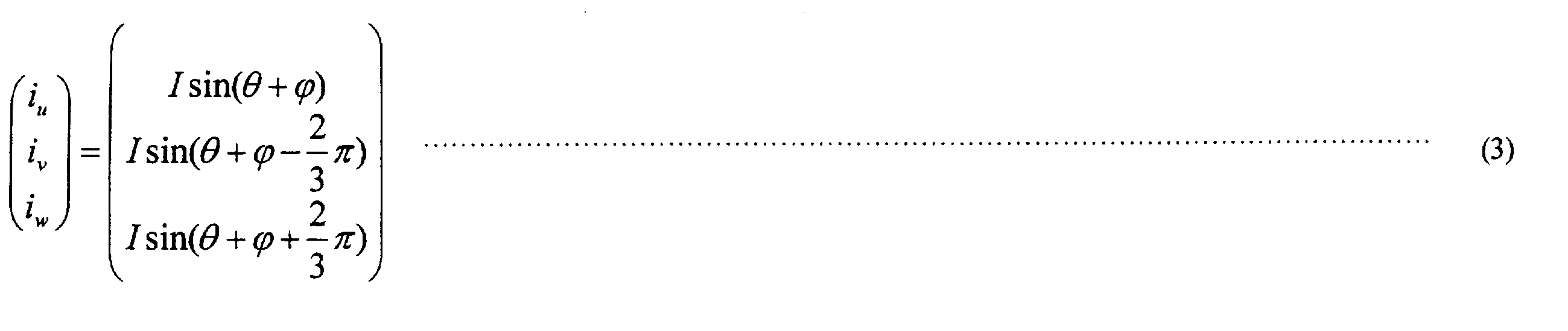
- ⁇ is a phase angle
- I is a current peak value
- currents i u , i v and i w are respectively given by equation (3).
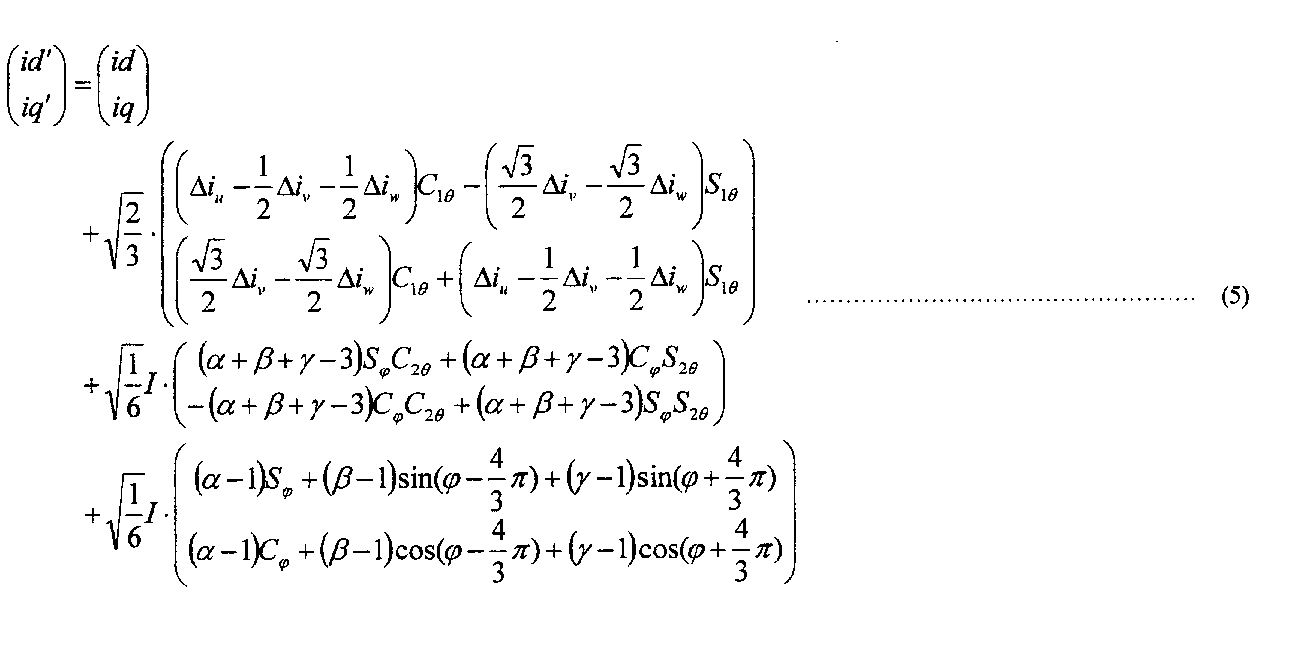
- the offset errors ⁇ i u , ⁇ i v , ⁇ i w and the gain errors ⁇ , ⁇ , ⁇ are generated, and the three-phase currents i ′ u , i ′ v , i ′ w have detection errors (4) It is expressed by a formula.
- equation (5) can be expanded with respect to id ′ and iq ′ where offset and gain errors exist.
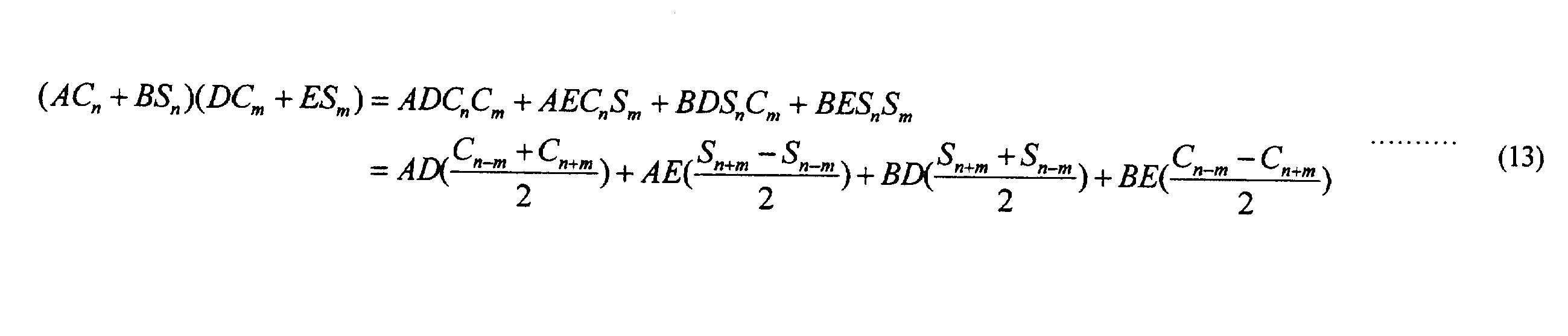
- the equation (5) can be expressed by the equation (6) with the terms of the rotational synchronization frequency 1f as id 1f and iq 1f and the terms of 2f as id 2f and iq 2f and the constant terms as Dd and Dq.
- the detection phase is U and V phases.
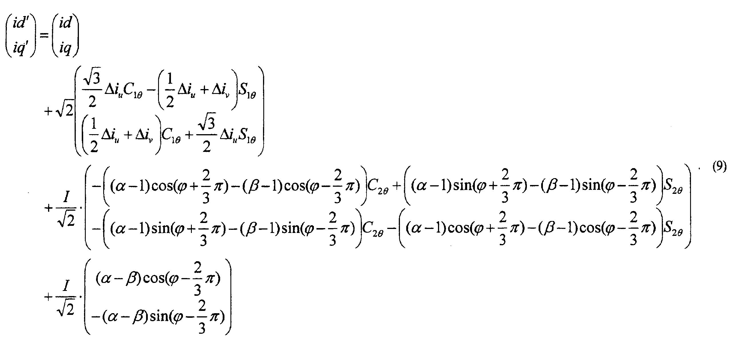
- the dq coordinate conversion equation from i u and i v to id and iq at the time of two-phase detection can be expressed by equation (7).
- the influence of idq on the torque due to the vibration state will be described. Assuming that idq in the equation (6) is energized, the output torque can be expressed as the equation (11) from the equation (10) which is a general torque equation of the PM motor.
- Ld d-axis inductance
- Lq q-axis inductance
- ⁇ flux linkage number
- Patent Document 1 and Non-Patent Document 1 have proposed using a periodic disturbance observer or the like.
- a torque is a control object to generate a compensation signal to suppress torque ripple.
- torque ripple can be reduced by this, it is necessary to install a torque sensor outside. Since the sensor error in the control device is a factor, it is considered that torque ripple can be reduced without using an extra measuring device if the sensor gain and the offset or the detected current can be appropriately adjusted.
- the increase in operation load is suppressed without using the torque sensor, and the periodic disturbance due to the current sensor error is suppressed.
- production by said current sensor is a problem applicable not only to the combination of an inverter and a motor but the control apparatus general (electric power system apparatus etc.) using a current sensor. Therefore, although each Example shown below is demonstrated by the example of an inverter and a motor, it is applicable to a general control apparatus.
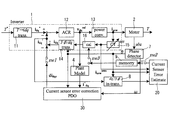
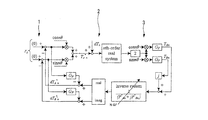
- FIG. 1 is a control block diagram of current detection error correction.
- Reference numeral 1 denotes an inverter serving as a control device
- 2 denotes a motor to be controlled
- 3 denotes a periodic disturbance observer.
- the inverter 1 the torque command value T * d, the current command value of q-axis i * dq (i d, i q) a conversion unit 11 for converting the output i * dq current sensor 15 and 3 of the converter unit
- the current control unit 12 calculates the voltage command value v dq ref based on the difference from the signal idq detected through the phase / phase coordinate conversion unit 14.
- the angular velocity ⁇ is output to the periodic disturbance observer 3 and the coordinate inverse conversion unit 6 and the three-phase / two-phase conversion unit 14.
- the G F in the periodic disturbance observer lowpass filter, di DQC compensation i d, i q value, di * dqn compensation i d, a i q command value.
- Plant model section 4 calculates a virtual current i ⁇ dq by the motor circuit equation (i d, i q) inputs an output v dq ref command of the current control unit 12, to do this and the vibration suppression target. If an error occurs in the current sensor, the current control unit 12 suppresses the detected vibration on idq within the response range of the current control unit 12. The vibration component is superimposed on the v dq ref command, whereby the output current vibrates and appears as a periodic disturbance. Therefore, no vibration is observed in idq inside the inverter. However, by passing the v dq ref command through the circuit equation of the plant model unit 4, observation of the virtual current value ⁇ dq of the vibration state becomes possible.
- the circuit equation in the plant model unit 4 uses the equation (14) when the target is a PM motor.
- R armature resistance
- Ld d-axis inductance
- Lq q-axis inductance
- ⁇ flux linkage number
- the parameter accuracy used for the circuit equation in the plant model unit 4 is not required to have high accuracy, and it may be within the robustness range of the periodic disturbance observer 3. For this reason, a design value etc. are applied, the system model inside the periodic disturbance observer 3 can be calculated in advance accordingly, and accurate acquisition by measurement etc. is not necessarily required.
- the coordinate conversion unit 5 performs harmonic dq conversion of equation (15).
- the current detection value can be directly compensated by reducing the periodic disturbance due to the current sensor error.
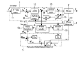
- FIG. 2 is a block diagram of current detection error correction according to the second embodiment.
- the error value of the current sensor can not be determined directly. If it is better to learn the error value and correct the sensor output directly if the sensor error does not change frequently, etc., it is more useful in terms of calculation load and control response, so this example is not necessary. And the function of estimating the error value of the current sensor error in detail.
- reference numeral 20 denotes a current sensor error estimation unit, which includes an offset error calculation unit 21 and a gain error calculation unit 22.
- the periodic disturbance observer 30 is a periodic disturbance observer for current sensor error compensation including the conversion units 5 and 6 shown in FIG. 1, and 8 is a two-phase / three-phase coordinate conversion unit. is there.
- the current i d estimates the sensor error by comparing the i uvw sens value before correction at the output of the compensation values i dq 'current sensor 15 i q.
- the DC component and 1f component of the current i uvw sens and the i dq ′ converted into three phases by the coordinate conversion unit 8 Extract the absolute value of
- the sensor error i dq ' is not generated, i uvw sens reversed is observed in a state where the sensor error occurs in the true value. Therefore, it is possible to estimate a sensor error by comparing the two.
- the offset error can be obtained by taking the difference between the two. Further, the same calculation is performed for the gain error calculation unit 22, and for the gain error, an error value is obtained by division.
- the error value is learned, and the calculation load is directly added to the detection value of the current sensor 15 based on the obtained error value. And control responsiveness can be improved.
- FIG. 3 is a control block diagram of current detection error correction according to the third embodiment.
- the switch is used to switch whether to use the compensation current value by the periodic disturbance observer 30 for current sensor error compensation or to directly correct the sensor output by the error estimated value stored in the memory. is there.
- 9 is a memory
- 16 is a current error calculation unit
- SW1 to SW3 are switches.
- the error value is stored in the memory 9 by turning on the switches SW2 and SW3 when it is estimated that the sensor error does not change by learning of the error value by the current sensor error estimating unit 20.
- the current error calculation unit 16 in the inverter refers to the estimated error value stored in the memory 9 to execute a correction operation on the output value i uvw sens of the current sensor 15 and outputs it to the coordinate conversion unit 14.
- the calculation load can be reduced thereafter.
- the response of the periodic disturbance observer is limited by the response of the periodic disturbance observer with respect to the response of the compensation.
- the current sensor error can be corrected with good response by directly compensating with the estimated error value.
- the number of detection phases of the current sensor is an example of three-phase detection (only three-phase detection is applicable and not only effective two-phase detection), but in the case of two-phase detection Can directly estimate the sensor error value from the vibration suppression compensation value.
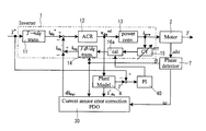
- reference numeral 10 denotes a function component detection unit, which inputs the output ⁇ q of the plant model unit 4 as a suppression target and outputs it to the periodic disturbance observer 3. Further, ⁇ q is also input to a compensation / error conversion unit 6a that converts the compensation value into an error, and a correction signal is output from the compensation / error conversion unit 6a to the current error calculation unit 16.
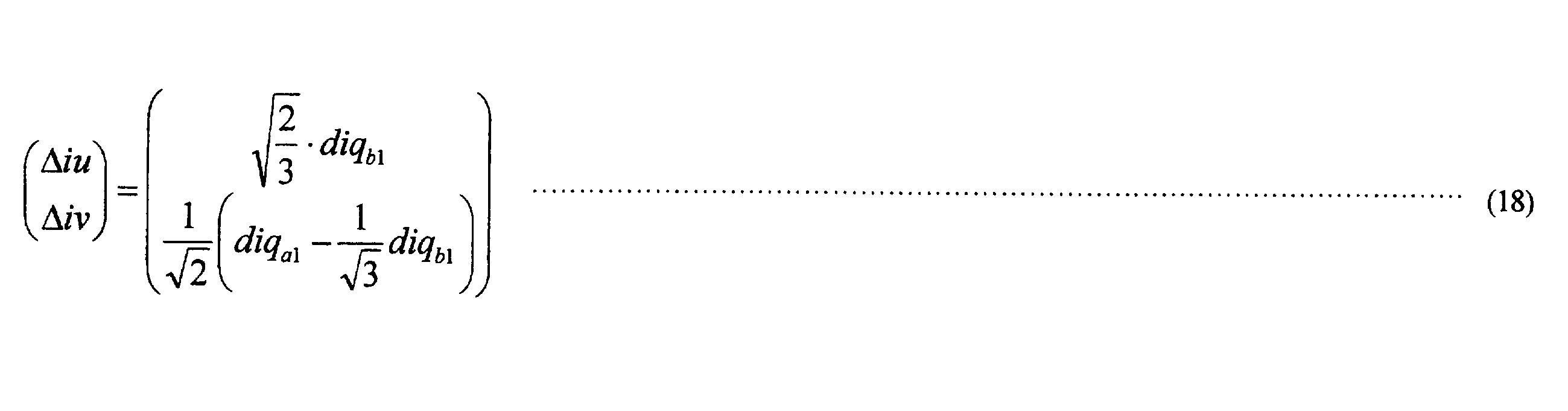
- Equation (18) is derived from the coefficient comparison with equation (9) for the offset error.
- Equation (21) is derived from the coefficient comparison with equation (9) for gain error. At this time, however, there is no balance in the gain error, and the condition of the equation (20) is satisfied.
- the condition of equation (20) is applied to the case where the non-equilibrium component and the equilibrium component are mixed, the non-equilibrium component error is compensated and the vibration is suppressed but the equilibrium component DC error remains.
- the equilibrium error means the same direction error of each sensor (two sensor errors are equal to ⁇ x%) and the non-balance error as different direction errors of each sensor (two sensor errors are + x%,- defined as y%).
- the sensor error value is determined by converting the compensation value of the periodic disturbance observer 3 output di qcn by the conversion unit 6a using Eqs. (18) and (21), and the detected value of the sensor output is directly corrected to make a cycle due to the sensor error Suppress disturbances.
- the U and V phase detection has been described in the present embodiment, the basic method is the same except that the form of the equation (9) changes with combinations of other phases.
- q axis was made into the suppression object in the above, it can carry out similarly as d axis.
- the controller of the two-phase detection type is provided with an estimation function of the sensor error value that suppresses the vibration due to the current sensor error with respect to the control target in which the periodic disturbance occurs due to the current sensor error. It is possible to directly estimate the current sensor error.
- the periodic disturbance observer 3 need not always be operated. Therefore, in the fifth embodiment, the compensation current value by the periodic disturbance observer 3 is used, or the compensation current value is configured to be applied by a fixed value stored in the memory or to be switched by the switch SW.
- FIG. 5 shows a control block of the periodic disturbance observer of this embodiment.
- the functions of the function component detection unit 10 and the conversion unit 6a shown in FIG. 4 are incorporated in the periodic disturbance observer 30a for current sensor error compensation. ing.
- the estimated error value (offset error, gain error) calculated by the periodic disturbance observer 30 a is stored in the memory 9 and is input to the current error calculation unit 16 through the contact b of the switch SW.
- the estimated error value stored in the memory 9 is input to the current error calculation unit 16 through the contact a of the switch SW.
- the switch SW switches from the contact b to the contact a when it is determined that the vibration suppression control has converged.
- the calculation load can be reduced thereafter.
- the calculation load can be reduced thereafter.
- This embodiment is to correct the influence of the sensor error on the average torque.
- the correction can not be performed. Further, in the method of the first embodiment (FIG. 1), the DC error due to the gain error shown in the equation (5) is not corrected.
- the sixth embodiment also corrects the influence of the sensor error on the average torque.
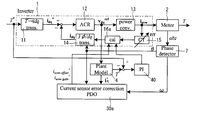
- 6 shows the case where the average torque correction function is added to the first embodiment shown in FIG. 1
- FIG. 7 shows the case where the average torque correction function is added to the fourth embodiment in FIG.
- the current error calculation units 16a and 16b provided in FIGS. 6 and 7 are portions different from those in FIGS.
- each parameter accuracy applied to the circuit equation of the motor is sufficient for the average torque. If the virtual current value ⁇ dq value obtained from the circuit equation of the plant model unit 4 is applied to the equation (10), the output torque T can be estimated as T ⁇ . The gain of all phases of the current sensor is corrected so as to reduce the error by comparing the output torque T ⁇ and the torque command value T * .
- a PI control unit 40 shown in FIG. 6 is applied for error reduction. Note that this error reduction operation can be achieved by using a method other than PI operation.
Landscapes
- Engineering & Computer Science (AREA)
- Software Systems (AREA)
- Artificial Intelligence (AREA)
- Computer Vision & Pattern Recognition (AREA)
- Evolutionary Computation (AREA)
- Medical Informatics (AREA)
- Health & Medical Sciences (AREA)
- Physics & Mathematics (AREA)
- General Physics & Mathematics (AREA)
- Automation & Control Theory (AREA)
- Power Engineering (AREA)
- Control Of Ac Motors In General (AREA)
- Feedback Control In General (AREA)
Abstract
Description
1はトルクリプル補償値演算部で、正弦波/余弦波の制御指令rn(通常は0)と周期外乱オブザーバ3による推定値dTA^n, dTB^nとの差分にそれぞれ正弦波/余弦波値を乗算してそれを加算することでトルクリプル補償指令Tc*nを生成し制御対象2に出力される。制御対象2では、周期の外乱(以下周期外乱dTnという)が発生することがある。例えば、制御対象がモータであればコギングトルなどによる回転数に同期した外乱であるトルクリプルがこれに相当し、振動や騒音の要因となる。
これにより比較的単純な制御構成でありながら、対象とした周波数に対しては次数に関係なく高い抑制効果が得られる。
P^n=P^An+jP^Bn …(1)
ただし、添字のnはn次成分、変数は何れもXn=XAn+jXBnと表現される複素ベクトルである。
なお、システム同定モデルに限らず文中記載のP^n,rn,dTn,dT^n,Tnも
Xn=XAn+jXBnと表現される複素ベクトルである。
複素ベクトル表現を用いた周期外乱オブザーバに基づくPMモータのトルクリプル抑制制御法、電気学会論文誌D、Vol.132, No.1.p.84-93(2012)
前記電圧指令値をプラントモデル部へ入力して仮想電流値を演算し、仮想電流値は座標変換部を介して周期外乱オブザーバに入力して、周期外乱オブザーバにて補償値を算出し、算出された補償値を座標逆変換部を介して前記検出電流値に重畳して、電流センサの検出電流値を補正することを特徴としたものである。
前記電流センサは2相検出とし、電流センサの出力側に電流誤差演算部を設け、前記電圧指令値をプラントモデル部へ入力して仮想電流値を演算し、前記仮想電流値は関数成分検出部を介して周期外乱オブザーバに入力し、この周期外乱オブザーバにて算出された補償値と前記仮想電流値を補償値/誤差変換部へ入力して電流センサ誤差推定値を算出し、この電流センサ誤差推定値を前記電流誤差演算部に入力して、電流センサの検出電流値を補正することを特徴としたものである。
なお、インバータ駆動において、電流制御のための3相交流電流検出方法については、3相それぞれに検出器を設ける場合と2相に検出器を設けて残りを演算から求める2つの場合がある。それぞれの形態について、センサ誤差の影響に若干の差異があるため、分けて説明する。
先ず、一般的に電流iu,iv,iwからidqへのdq座標変換式は(2)式に表せる。ここでCnθ、Snθはcosは(nθ),sin(nθ)を示す。



1-2. 2相検知におけるセンサ誤差の影響について
検出相はU,V相とした2相検知時のiu,ivからid,iqへのdq座標変換式は(7)式に表せる。

ら(8)式で算出される。

iq´'に関して展開すると(9)式となる。また(9)式も(6)式として表すことができる。
(6)式のidqが通電されているとして、PMモータの一般的なトルク式である(10)式から出力トルクを(11)式と表すことができる。





idqn=idn+jiqnとして扱う。ここからは通常の周期外乱オブザーバ3の制御則に従い補償値を算出する。
最後に座標逆変換部6では、補償値を(16)式の座標系逆変換によりdq座標系に変換する。

idq´とし、更にi* dqとの差分を得て電流制御部12に入力する。
また、ゲイン誤差演算部22についても同様の演算を行い、ゲイン誤差については除算により誤差値を求める。
図2で示した実施例において、電流センサ誤差を推定して直接電流センサ15の出力が補正できれば、周期外乱オブザーバ30を常に動作させる必要はない。よって実施例3では、電流センサ誤差補償用の周期外乱オブザーバ30による補償電流値を用いるか、メモリに保存した誤差推定値により直接センサ出力に補正を行うかをスイッチにより切り替えるように構成したものである。
スイッチSW2,SW3はオフ状態となり、スイッチSW1がオン状態となる。
この状態では、周期外乱オブザーバ30からの補償値didqcと検出値idqとの差演算を行ってidq´を求め、このidq´と指令値i* dqとの差分が得られる。
オフセット誤差について(9)式との係数比較により(18)式を導く。

ゲイン誤差について(9)式との係数比較により(21)式を導く。ただし、この時ゲイン誤差に平衡分はなく、(20)式の条件を満たしているものとする。
(20)式の条件を非平衡分と平衡分が混在する場合に適用すると、非平衡分の誤差は補償されて振動は抑制されるが平衡分の直流誤差が残留する。なお、ここで、平衡誤差とは、各センサの同一方向誤差(2つのセンサ誤差が±x%と同じ)と、非平衡誤差を各センサの異方向誤差(2つのセンサ誤差が+x%,-y%と異なる)と定義する。



また、上記ではq軸を抑制対象としたが、d軸としても同様に行える。
Claims (7)
- 電流指令値と、電流センサによる電流検出値から、電流制御部によって電圧指令値を生成する制御装置において、
前記電圧指令値をプラントモデル部へ入力して仮想電流値を演算し、仮想電流値は座標変換部を介して周期外乱オブザーバに入力して、周期外乱オブザーバにて補償値を算出し、算出された補償値を座標逆変換部を介して前記検出電流値に重畳して、電流センサの検出電流値を補正することを特徴とした制御装置。 - オフセット誤差演算部とゲイン誤差演算部を有する電流センサ誤差推定部を設け、前記検出電流値と前記補償値の重畳された値と、前記検出電流値をそれぞれオフセット誤差演算部とゲイン誤差演算部に入力してオフセット誤差とゲイン誤差を算出し、算出された各誤差信号に基づいて前記電流センサの誤差の推定を行うことを特徴とした請求項1記載の制御装置。
- 前記電流センサの出力側に電流誤差演算部を設け、前記電流センサ誤差推定部の出力側にスイッチを介して電流センサ誤差推定値を保存するメモリを設け、前記周期外乱オブザーバによる補償値の出力側にスイッチを接続し、前記メモリに保存された電流センサ誤差推定値と周期外乱オブザーバによる補償値を切替えて出力するよう構成し、
前記電流誤差演算部は、前記メモリに接続されたスイッチがオン状態となったときメモリに保存された電流センサ誤差推定値に基づいて検出電流値を補正することを特徴とした請求項2記載の制御装置。 - 電流指令値と、電流センサによる電流検出値から、電流制御部によって電圧指令値を生成する制御装置において、
前記電流センサは2相検出とし、電流センサの出力側に電流誤差演算部を設け、前記電圧指令値をプラントモデル部へ入力して仮想電流値を演算し、前記仮想電流値は関数成分検出部を介して周期外乱オブザーバに入力し、この周期外乱オブザーバにて算出された補償値と前記仮想電流値を補償値/誤差変換部へ入力して電流センサ誤差推定値を算出し、この電流センサ誤差推定値を前記電流誤差演算部に入力して、電流センサの検出電流値を補正することを特徴とした制御装置。 - 前記周期外乱オブザーバの出力側は、スイッチを介して前記電流誤差演算部に接続すると共に、周期外乱オブザーバの出力側に補償値を保存するメモリを設け、振動の抑制制御が収束したとき、前記メモリに保存された補償値に基づいて検出電流値を補正することを特徴とした請求項4記載の制御装置。
- 前記電流指令値をトルク制御指令値に基づいて生成すると共に、前記電流センサの出力側に電流誤差演算部を設け、前記プラントモデル部は出力トルクの推定値を出力して前記トルク制御指令値と比較して誤差を低減するように前記電流誤差演算部に出力することを特徴とした請求項1又は2記載の周期外乱自動抑制装置。
- 前記電流指令値をトルク制御指令値に基づいて生成し、前記プラントモデル部は出力トルクの推定値を出力して前記トルク制御指令値と比較して誤差を低減するように前記電流誤差演算部に出力することを特徴とした請求項4記載の周期外乱自動抑制装置。
Priority Applications (3)
| Application Number | Priority Date | Filing Date | Title |
|---|---|---|---|
| US14/917,714 US9973128B2 (en) | 2013-09-30 | 2014-09-25 | Control device |
| CN201480053893.4A CN105593770B (zh) | 2013-09-30 | 2014-09-25 | 控制装置 |
| KR1020167008175A KR101699463B1 (ko) | 2013-09-30 | 2014-09-25 | 제어 장치 |
Applications Claiming Priority (2)
| Application Number | Priority Date | Filing Date | Title |
|---|---|---|---|
| JP2013203386A JP5929863B2 (ja) | 2013-09-30 | 2013-09-30 | 制御装置 |
| JP2013-203386 | 2013-09-30 |
Publications (1)
| Publication Number | Publication Date |
|---|---|
| WO2015046286A1 true WO2015046286A1 (ja) | 2015-04-02 |
Family
ID=52743420
Family Applications (1)
| Application Number | Title | Priority Date | Filing Date |
|---|---|---|---|
| PCT/JP2014/075351 Ceased WO2015046286A1 (ja) | 2013-09-30 | 2014-09-25 | 制御装置 |
Country Status (5)
| Country | Link |
|---|---|
| US (1) | US9973128B2 (ja) |
| JP (1) | JP5929863B2 (ja) |
| KR (1) | KR101699463B1 (ja) |
| CN (1) | CN105593770B (ja) |
| WO (1) | WO2015046286A1 (ja) |
Cited By (1)
| Publication number | Priority date | Publication date | Assignee | Title |
|---|---|---|---|---|
| CN106849770A (zh) * | 2015-10-14 | 2017-06-13 | 现代自动车株式会社 | 用于补偿扰动的电机控制系统及方法 |
Families Citing this family (16)
| Publication number | Priority date | Publication date | Assignee | Title |
|---|---|---|---|---|
| JP6183554B2 (ja) * | 2014-06-06 | 2017-08-23 | 株式会社明電舎 | 周期外乱自動抑制装置 |
| NL2016797A (en) * | 2015-06-19 | 2016-12-22 | Asml Netherlands Bv | Control system, positioning system, lithographic apparatus and device manufacturing method. |
| US10666180B2 (en) * | 2015-07-22 | 2020-05-26 | Texas Instruments Incorporated | Adaptive torque disturbance cancellation for electric motors |
| JP6257689B2 (ja) * | 2016-04-22 | 2018-01-10 | 三菱電機株式会社 | 同期機制御装置 |
| TWI634748B (zh) * | 2017-12-05 | 2018-09-01 | 財團法人工業技術研究院 | 量測系統及其鎖相迴路暨量測方法 |
| JP6888564B2 (ja) * | 2018-02-13 | 2021-06-16 | オムロン株式会社 | モデル予測制御装置、モデル予測制御装置の制御方法、情報処理プログラム、および記録媒体 |
| CN111239661B (zh) * | 2020-01-16 | 2022-02-18 | 西北工业大学 | 基于固定点采样的三相电流传感器误差校正系统及方法 |
| CN111181448B (zh) * | 2020-02-13 | 2022-02-18 | 西北工业大学 | 一种双电机群相电流传感器误差协同系统及校正方法 |
| CN111181447B (zh) * | 2020-02-13 | 2022-02-18 | 西北工业大学 | 基于自生探测信号电机群电流传感器协同系统及校正方法 |
| CN111313767B (zh) * | 2020-02-13 | 2022-06-14 | 西北工业大学 | 基于斩波周期正交双电机电流传感器协同系统及校正方法 |
| JP7348526B2 (ja) * | 2020-03-02 | 2023-09-21 | シンフォニアテクノロジー株式会社 | 共振抑制制御装置 |
| CN114123242B (zh) * | 2021-11-16 | 2024-11-12 | 泉州装备制造研究所 | 不平衡电网电压下的pwm整流器模型预测控制方法 |
| CN114462227A (zh) * | 2022-01-24 | 2022-05-10 | 深圳市艾锐达光电有限公司 | 一种电流补偿方法、系统、计算机设备及可读存储介质 |
| CN115128456B (zh) * | 2022-06-29 | 2023-04-07 | 哈尔滨工业大学 | 一种双余度电机开路故障检测及故障定位方法 |
| CN116733687B (zh) * | 2023-04-28 | 2024-01-12 | 广东工业大学 | 一种风机内部模态谐振的检测方法 |
| CN117148250B (zh) * | 2023-10-31 | 2024-02-09 | 江苏威进智控科技有限公司 | 一种交流电机定子电流传感器检测误差自校正方法 |
Citations (4)
| Publication number | Priority date | Publication date | Assignee | Title |
|---|---|---|---|---|
| JPH04299085A (ja) * | 1991-03-26 | 1992-10-22 | Omron Corp | モータ制御装置 |
| JP2002252991A (ja) * | 2001-02-26 | 2002-09-06 | Matsushita Electric Ind Co Ltd | モータ制御装置 |
| JP3813637B2 (ja) * | 1998-09-03 | 2006-08-23 | 三菱電機株式会社 | 交流電動機の制御装置 |
| JP2013183558A (ja) * | 2012-03-02 | 2013-09-12 | Aisin Seiki Co Ltd | モータ制御装置 |
Family Cites Families (5)
| Publication number | Priority date | Publication date | Assignee | Title |
|---|---|---|---|---|
| JP3655378B2 (ja) * | 1995-11-28 | 2005-06-02 | ファナック株式会社 | サーボモータの外乱負荷推定方法 |
| JP2006029938A (ja) * | 2004-07-15 | 2006-02-02 | Matsushita Electric Ind Co Ltd | 電流オフセット補償回路 |
| JP5088414B2 (ja) | 2008-08-26 | 2012-12-05 | 株式会社明電舎 | 電動機の外乱抑圧装置および外乱抑圧方法 |
| JP5644396B2 (ja) * | 2010-08-06 | 2014-12-24 | 株式会社明電舎 | 電力変換装置の高調波電流抑制装置および高調波電流抑制方法 |
| JP5786337B2 (ja) * | 2011-01-12 | 2015-09-30 | 株式会社明電舎 | インバータ制御システム |
-
2013
- 2013-09-30 JP JP2013203386A patent/JP5929863B2/ja not_active Expired - Fee Related
-
2014
- 2014-09-25 CN CN201480053893.4A patent/CN105593770B/zh active Active
- 2014-09-25 KR KR1020167008175A patent/KR101699463B1/ko active Active
- 2014-09-25 US US14/917,714 patent/US9973128B2/en active Active
- 2014-09-25 WO PCT/JP2014/075351 patent/WO2015046286A1/ja not_active Ceased
Patent Citations (4)
| Publication number | Priority date | Publication date | Assignee | Title |
|---|---|---|---|---|
| JPH04299085A (ja) * | 1991-03-26 | 1992-10-22 | Omron Corp | モータ制御装置 |
| JP3813637B2 (ja) * | 1998-09-03 | 2006-08-23 | 三菱電機株式会社 | 交流電動機の制御装置 |
| JP2002252991A (ja) * | 2001-02-26 | 2002-09-06 | Matsushita Electric Ind Co Ltd | モータ制御装置 |
| JP2013183558A (ja) * | 2012-03-02 | 2013-09-12 | Aisin Seiki Co Ltd | モータ制御装置 |
Cited By (2)
| Publication number | Priority date | Publication date | Assignee | Title |
|---|---|---|---|---|
| CN106849770A (zh) * | 2015-10-14 | 2017-06-13 | 现代自动车株式会社 | 用于补偿扰动的电机控制系统及方法 |
| CN106849770B (zh) * | 2015-10-14 | 2021-08-31 | 现代自动车株式会社 | 用于补偿扰动的电机控制系统及方法 |
Also Published As
| Publication number | Publication date |
|---|---|
| JP5929863B2 (ja) | 2016-06-08 |
| JP2015069439A (ja) | 2015-04-13 |
| US20160218652A1 (en) | 2016-07-28 |
| KR101699463B1 (ko) | 2017-01-24 |
| KR20160052603A (ko) | 2016-05-12 |
| CN105593770A (zh) | 2016-05-18 |
| CN105593770B (zh) | 2018-03-20 |
| US9973128B2 (en) | 2018-05-15 |
Similar Documents
| Publication | Publication Date | Title |
|---|---|---|
| JP5929863B2 (ja) | 制御装置 | |
| JP5637042B2 (ja) | 電動機の脈動抑制装置および電動機の脈動抑制方法 | |
| US9136785B2 (en) | Motor control system to compensate for torque ripple | |
| JP4221307B2 (ja) | 同期電動機の制御装置,電気機器およびモジュール | |
| JP5800108B2 (ja) | 周期外乱自動抑制装置 | |
| EP2779414A2 (en) | Motor control system having bandwidth compensation | |
| EP3032735A1 (en) | Motor drive system and motor control device | |
| JP5488043B2 (ja) | モータのトルク制御装置 | |
| JPWO2015025356A1 (ja) | モータ駆動システムおよびモータ制御装置 | |
| CN104052360B (zh) | 马达控制装置 | |
| JP6183554B2 (ja) | 周期外乱自動抑制装置 | |
| JP6519149B2 (ja) | モータ制御装置 | |
| JP2010035351A (ja) | 同期電動機のロータ位置推定装置 | |
| JP6032047B2 (ja) | モータ制御装置 | |
| JP6541092B2 (ja) | 永久磁石同期電動機の制御装置 | |
| JP6398462B2 (ja) | 位置およびトルクセンサレスによるトルクリプル抑制装置 | |
| JP4657892B2 (ja) | Dcブラシレスモータのロータ角度推定装置およびロータ角度推定方法 | |
| KR20210137190A (ko) | 모터 구동 장치 및 그것을 사용한 공기 조화기의 실외기 | |
| JP5106295B2 (ja) | 同期電動機のロータ位置推定装置 | |
| JP2016019341A (ja) | 三相交流回転機の制御装置 | |
| JP6108114B2 (ja) | 永久磁石形同期電動機の制御装置 | |
| JP5312195B2 (ja) | Dcブラシレスモータの制御装置 | |
| JP4680754B2 (ja) | Dcブラシレスモータのロータ角度推定方法及びdcブラシレスモータの制御装置 | |
| JP6459710B2 (ja) | q軸インダクタンスの推定方法及び推定装置 |
Legal Events
| Date | Code | Title | Description |
|---|---|---|---|
| 121 | Ep: the epo has been informed by wipo that ep was designated in this application |
Ref document number: 14847409 Country of ref document: EP Kind code of ref document: A1 |
|
| WWE | Wipo information: entry into national phase |
Ref document number: 14917714 Country of ref document: US |
|
| ENP | Entry into the national phase |
Ref document number: 20167008175 Country of ref document: KR Kind code of ref document: A |
|
| NENP | Non-entry into the national phase |
Ref country code: DE |
|
| 122 | Ep: pct application non-entry in european phase |
Ref document number: 14847409 Country of ref document: EP Kind code of ref document: A1 |