WO2015046160A1 - レーザ装置 - Google Patents
レーザ装置 Download PDFInfo
- Publication number
- WO2015046160A1 WO2015046160A1 PCT/JP2014/075120 JP2014075120W WO2015046160A1 WO 2015046160 A1 WO2015046160 A1 WO 2015046160A1 JP 2014075120 W JP2014075120 W JP 2014075120W WO 2015046160 A1 WO2015046160 A1 WO 2015046160A1
- Authority
- WO
- WIPO (PCT)
- Prior art keywords
- fiber
- light
- laser
- optical
- optical fiber
- Prior art date
- Legal status (The legal status is an assumption and is not a legal conclusion. Google has not performed a legal analysis and makes no representation as to the accuracy of the status listed.)
- Ceased
Links
Images


Classifications
-
- H—ELECTRICITY
- H01—ELECTRIC ELEMENTS
- H01S—DEVICES USING THE PROCESS OF LIGHT AMPLIFICATION BY STIMULATED EMISSION OF RADIATION [LASER] TO AMPLIFY OR GENERATE LIGHT; DEVICES USING STIMULATED EMISSION OF ELECTROMAGNETIC RADIATION IN WAVE RANGES OTHER THAN OPTICAL
- H01S3/00—Lasers, i.e. devices using stimulated emission of electromagnetic radiation in the infrared, visible or ultraviolet wave range
- H01S3/09—Processes or apparatus for excitation, e.g. pumping
- H01S3/091—Processes or apparatus for excitation, e.g. pumping using optical pumping
- H01S3/094—Processes or apparatus for excitation, e.g. pumping using optical pumping by coherent light
- H01S3/094049—Guiding of the pump light
- H01S3/094053—Fibre coupled pump, e.g. delivering pump light using a fibre or a fibre bundle
-
- G—PHYSICS
- G02—OPTICS
- G02B—OPTICAL ELEMENTS, SYSTEMS OR APPARATUS
- G02B6/00—Light guides; Structural details of arrangements comprising light guides and other optical elements, e.g. couplings
- G02B6/24—Coupling light guides
- G02B6/42—Coupling light guides with opto-electronic elements
- G02B6/4201—Packages, e.g. shape, construction, internal or external details
- G02B6/4204—Packages, e.g. shape, construction, internal or external details the coupling comprising intermediate optical elements, e.g. lenses, holograms
- G02B6/421—Packages, e.g. shape, construction, internal or external details the coupling comprising intermediate optical elements, e.g. lenses, holograms the intermediate optical component consisting of a short length of fibre, e.g. fibre stub
-
- H—ELECTRICITY
- H01—ELECTRIC ELEMENTS
- H01S—DEVICES USING THE PROCESS OF LIGHT AMPLIFICATION BY STIMULATED EMISSION OF RADIATION [LASER] TO AMPLIFY OR GENERATE LIGHT; DEVICES USING STIMULATED EMISSION OF ELECTROMAGNETIC RADIATION IN WAVE RANGES OTHER THAN OPTICAL
- H01S3/00—Lasers, i.e. devices using stimulated emission of electromagnetic radiation in the infrared, visible or ultraviolet wave range
- H01S3/09—Processes or apparatus for excitation, e.g. pumping
- H01S3/091—Processes or apparatus for excitation, e.g. pumping using optical pumping
- H01S3/094—Processes or apparatus for excitation, e.g. pumping using optical pumping by coherent light
- H01S3/0941—Processes or apparatus for excitation, e.g. pumping using optical pumping by coherent light of a laser diode
-
- H—ELECTRICITY
- H01—ELECTRIC ELEMENTS
- H01S—DEVICES USING THE PROCESS OF LIGHT AMPLIFICATION BY STIMULATED EMISSION OF RADIATION [LASER] TO AMPLIFY OR GENERATE LIGHT; DEVICES USING STIMULATED EMISSION OF ELECTROMAGNETIC RADIATION IN WAVE RANGES OTHER THAN OPTICAL
- H01S3/00—Lasers, i.e. devices using stimulated emission of electromagnetic radiation in the infrared, visible or ultraviolet wave range
- H01S3/10—Controlling the intensity, frequency, phase, polarisation or direction of the emitted radiation, e.g. switching, gating, modulating or demodulating
- H01S3/102—Controlling the intensity, frequency, phase, polarisation or direction of the emitted radiation, e.g. switching, gating, modulating or demodulating by controlling the active medium, e.g. by controlling the processes or apparatus for excitation
- H01S3/1022—Controlling the intensity, frequency, phase, polarisation or direction of the emitted radiation, e.g. switching, gating, modulating or demodulating by controlling the active medium, e.g. by controlling the processes or apparatus for excitation by controlling the optical pumping
-
- H—ELECTRICITY
- H01—ELECTRIC ELEMENTS
- H01S—DEVICES USING THE PROCESS OF LIGHT AMPLIFICATION BY STIMULATED EMISSION OF RADIATION [LASER] TO AMPLIFY OR GENERATE LIGHT; DEVICES USING STIMULATED EMISSION OF ELECTROMAGNETIC RADIATION IN WAVE RANGES OTHER THAN OPTICAL
- H01S3/00—Lasers, i.e. devices using stimulated emission of electromagnetic radiation in the infrared, visible or ultraviolet wave range
- H01S3/14—Lasers, i.e. devices using stimulated emission of electromagnetic radiation in the infrared, visible or ultraviolet wave range characterised by the material used as the active medium
- H01S3/16—Solid materials
- H01S3/163—Solid materials characterised by a crystal matrix
- H01S3/164—Solid materials characterised by a crystal matrix garnet
- H01S3/1643—YAG
-
- H—ELECTRICITY
- H01—ELECTRIC ELEMENTS
- H01S—DEVICES USING THE PROCESS OF LIGHT AMPLIFICATION BY STIMULATED EMISSION OF RADIATION [LASER] TO AMPLIFY OR GENERATE LIGHT; DEVICES USING STIMULATED EMISSION OF ELECTROMAGNETIC RADIATION IN WAVE RANGES OTHER THAN OPTICAL
- H01S3/00—Lasers, i.e. devices using stimulated emission of electromagnetic radiation in the infrared, visible or ultraviolet wave range
- H01S3/14—Lasers, i.e. devices using stimulated emission of electromagnetic radiation in the infrared, visible or ultraviolet wave range characterised by the material used as the active medium
- H01S3/16—Solid materials
- H01S3/163—Solid materials characterised by a crystal matrix
- H01S3/1671—Solid materials characterised by a crystal matrix vanadate, niobate, tantalate
- H01S3/1673—YVO4 [YVO]
-
- H—ELECTRICITY
- H01—ELECTRIC ELEMENTS
- H01S—DEVICES USING THE PROCESS OF LIGHT AMPLIFICATION BY STIMULATED EMISSION OF RADIATION [LASER] TO AMPLIFY OR GENERATE LIGHT; DEVICES USING STIMULATED EMISSION OF ELECTROMAGNETIC RADIATION IN WAVE RANGES OTHER THAN OPTICAL
- H01S2301/00—Functional characteristics
- H01S2301/20—Lasers with a special output beam profile or cross-section, e.g. non-Gaussian
- H01S2301/206—Top hat profile
-
- H—ELECTRICITY
- H01—ELECTRIC ELEMENTS
- H01S—DEVICES USING THE PROCESS OF LIGHT AMPLIFICATION BY STIMULATED EMISSION OF RADIATION [LASER] TO AMPLIFY OR GENERATE LIGHT; DEVICES USING STIMULATED EMISSION OF ELECTROMAGNETIC RADIATION IN WAVE RANGES OTHER THAN OPTICAL
- H01S3/00—Lasers, i.e. devices using stimulated emission of electromagnetic radiation in the infrared, visible or ultraviolet wave range
- H01S3/09—Processes or apparatus for excitation, e.g. pumping
- H01S3/091—Processes or apparatus for excitation, e.g. pumping using optical pumping
- H01S3/094—Processes or apparatus for excitation, e.g. pumping using optical pumping by coherent light
- H01S3/094065—Single-mode pumping
-
- H—ELECTRICITY
- H01—ELECTRIC ELEMENTS
- H01S—DEVICES USING THE PROCESS OF LIGHT AMPLIFICATION BY STIMULATED EMISSION OF RADIATION [LASER] TO AMPLIFY OR GENERATE LIGHT; DEVICES USING STIMULATED EMISSION OF ELECTROMAGNETIC RADIATION IN WAVE RANGES OTHER THAN OPTICAL
- H01S3/00—Lasers, i.e. devices using stimulated emission of electromagnetic radiation in the infrared, visible or ultraviolet wave range
- H01S3/09—Processes or apparatus for excitation, e.g. pumping
- H01S3/091—Processes or apparatus for excitation, e.g. pumping using optical pumping
- H01S3/094—Processes or apparatus for excitation, e.g. pumping using optical pumping by coherent light
- H01S3/0941—Processes or apparatus for excitation, e.g. pumping using optical pumping by coherent light of a laser diode
- H01S3/09415—Processes or apparatus for excitation, e.g. pumping using optical pumping by coherent light of a laser diode the pumping beam being parallel to the lasing mode of the pumped medium, e.g. end-pumping
-
- H—ELECTRICITY
- H01—ELECTRIC ELEMENTS
- H01S—DEVICES USING THE PROCESS OF LIGHT AMPLIFICATION BY STIMULATED EMISSION OF RADIATION [LASER] TO AMPLIFY OR GENERATE LIGHT; DEVICES USING STIMULATED EMISSION OF ELECTROMAGNETIC RADIATION IN WAVE RANGES OTHER THAN OPTICAL
- H01S3/00—Lasers, i.e. devices using stimulated emission of electromagnetic radiation in the infrared, visible or ultraviolet wave range
- H01S3/14—Lasers, i.e. devices using stimulated emission of electromagnetic radiation in the infrared, visible or ultraviolet wave range characterised by the material used as the active medium
- H01S3/16—Solid materials
- H01S3/1601—Solid materials characterised by an active (lasing) ion
- H01S3/1603—Solid materials characterised by an active (lasing) ion rare earth
- H01S3/1611—Solid materials characterised by an active (lasing) ion rare earth neodymium
Definitions
- the present invention relates to a laser device.
- a light source that emits light, an optical fiber that guides and emits light emitted from the light source, and light that is emitted from the optical fiber is incident on a laser medium to emit laser light.
- a laser oscillator is known (see, for example, Patent Documents 1 and 2 and Non-Patent Documents 1 and 2).
- the output of the laser beam may become unstable or the output of the laser beam may decrease.
- an object of the present invention is to provide a laser device that can obtain a laser beam having a stable and sufficient output.
- the present inventors have found that in a conventional laser apparatus, the phenomenon that the output of laser light becomes unstable or the output of laser light decreases is a light source. We found out that this is due to the characteristics of the optical fiber that guides light to the laser medium.
- an SI (Step Index) fiber or a GI (Graded Index) fiber is generally used as an optical fiber for guiding light from a light source to a laser medium.
- the refractive index of the core is constant, and the beam profile of the guided light tends to be a top hat shape. If the beam profile of the light incident on the laser medium has a top hat shape, the output of the laser light emitted from the laser oscillator tends to be sufficient.
- the SI fiber has a constant core refractive index, and the light propagation speed differs between the core center and the periphery, so that the output of the guided light is easily affected by changes in the shape of the fiber and becomes unstable. easy. If the output of the light incident on the laser medium is unstable, the output of the laser light emitted from the laser oscillator tends to be unstable. Therefore, when an SI fiber is used as an optical fiber for guiding light from the light source to the laser medium, the output of the laser light emitted from the laser oscillator tends to be sufficient, but the output tends to become unstable.
- the refractive index of the GI fiber is not constant, and the light propagation speed is the same between the center and the periphery of the core, so that the output of the guided light is not easily affected by the shape change of the fiber and is stable. Easy to do. When the output of the light incident on the laser medium is stabilized, the output of the laser light emitted from the laser oscillator is easily stabilized.
- the refractive index of the core is not constant, and the beam profile of the guided light has a Gaussian waveform. If the beam profile of the light incident on the laser medium has a Gaussian waveform, the output of the laser light emitted from the laser oscillator tends to decrease. Therefore, when a GI fiber is used as an optical fiber for guiding light from the light source to the laser medium, the output of the laser light emitted from the laser oscillator is likely to be stable, but the output is likely to decrease.
- the laser device of the present invention allows a light source that emits light, light emitted from the light source to enter, an optical fiber that guides and emits the light, and light emitted from the optical fiber to enter.
- a laser oscillator that emits laser light, and an optical fiber includes a GI fiber forming a light incident side portion, and an SI fiber bonded to the GI fiber and forming a light emission side portion.
- the optical fiber on the light incident side where the light emitted from the light source is incident is made of a GI fiber
- the output of the light guided in this part is not easily affected by the shape change of the fiber. Easy to stabilize.
- the optical fiber on the light emitting side that emits the guided light is made of SI fiber
- the beam profile of the light emitted from the optical fiber is likely to have a top hat shape. For this reason, the light incident on the laser medium tends to have a stable output and a beam profile of a top hat shape. Therefore, according to this laser apparatus, it is possible to obtain a laser beam having a stable and sufficient output.
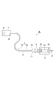
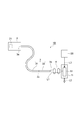
- FIG. 1 is a configuration diagram of the laser apparatus according to the first embodiment.
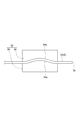
- FIG. 2 is a configuration diagram of the SI fiber fixture of the laser apparatus of FIG.
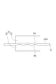
- FIG. 3 is a configuration diagram of another example of the SI fiber fixture of the laser apparatus of FIG.
- FIG. 4 is a configuration diagram of another example of the SI fiber fixture of the laser apparatus of FIG.
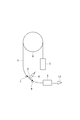
- FIG. 5 is a schematic diagram of an evaluation method for evaluating the influence of the shape change of the optical fiber.
- FIG. 6 is a graph showing an evaluation result of the influence of the shape change of the optical fiber.
- FIG. 7 is a configuration diagram of the laser apparatus of the second embodiment.
- FIG. 1 is a configuration diagram of the laser apparatus of the first embodiment.
- the laser device 1 ⁇ / b> A includes a semiconductor laser device 2, an optical fiber 3, an optical system 4, and an optical resonator (laser oscillator) 5.
- the semiconductor laser device 2 includes a semiconductor laser 21 and an optical system that focuses the excitation light L1 emitted from the semiconductor laser 21 on the incident end face 3a of the optical fiber 3.
- the excitation light L1 emitted from the semiconductor laser 21 as the light source is incident on the incident end face 3a of the optical fiber 3.
- the optical fiber 3 guides the excitation light L1 incident from the incident end face 3a and emits it from the exit end face 3b.
- the optical fiber 3 includes a GI fiber 31 forming a light incident side portion (a portion from the incident end surface 3a to the predetermined portion 3c of the optical fiber 3) and a light emission side portion (a portion from the emission end surface 3b to the predetermined portion 3c). And an SI fiber 32.
- the GI fiber 31 and the SI fiber 32 are joined by fusion joining or the like at the predetermined portion 3c.
- the length of the GI fiber 31 is preferably longer than the length of the SI fiber 32. In an example of the length of each of the fibers 31 and 32, the length of the GI fiber 31 is, for example, 15 cm or more, and the length of the SI fiber 32 is, for example, 15 cm or less.
- the GI fiber 31 and the SI fiber 32 preferably have their core diameters and numerical apertures set as follows in order to suppress light propagation loss at the bonding interface. That is, assuming that the core diameter of the GI fiber 31 is ⁇ GI , the numerical aperture of the GI fiber 31 is NA GI , the core diameter of the SI fiber 32 is ⁇ SI, and the numerical aperture of the SI fiber 32 is NA SI , the fiber 31, 32 preferably satisfies the following formula (1) when NA GI > NA SI , and satisfies the following formula (2) when NA GI ⁇ NA SI . 2 ⁇ GI (NA SI / NA GI ) ⁇ ⁇ SI ⁇ GI (NA SI / NA GI ) (1) 2 ⁇ GI ⁇ ⁇ SI ⁇ ⁇ GI (2)
- the optical system 4 is a condensing lens system, and condenses the excitation light L ⁇ b> 1 emitted from the emission end face 3 b of the optical fiber 3 on the optical resonator 5.
- the optical resonator 5 includes a laser medium 51 and a total reflection mirror 52 and a partial reflection mirror 53 that face each other with the laser medium 51 interposed therebetween.
- the laser medium 51 for example, a solid laser medium doped with neodymium (Nd) as a laser active species in a laser medium such as YAG (Y 3 Al 5 O 12 ) or YVO 4 can be used.
- the laser medium 51 when the excitation light L1 collected by the optical system 4 is incident, the laser active species is excited and light having a predetermined wavelength is emitted.
- the total reflection mirror 52 transmits the excitation light L1 and totally reflects light spontaneously emitted by the laser medium 51.
- the partial reflection mirror 53 has a lower reflectance than the total reflection mirror 52 with respect to the wavelength of light spontaneously emitted by the laser medium 51.
- the total reflection mirror 52 and the partial reflection mirror 53 reflect the light emitted from the laser medium 51, respectively, and reciprocate between them to generate stimulated emission in the laser medium 51.
- the optical resonator 5 emits the laser beam L2 from the partial reflection mirror 53.
- the optical resonator 5 may be a composite crystal in which the total reflection mirror 52 to the partial reflection mirror 53 are integrated.
- FIG. 2 is a configuration diagram of the SI fiber fixture of the laser apparatus of FIG.
- the SI fiber 32 is fixed in a curved state by a fixture 33.
- the fixture 33 includes plate members 34 and 35.
- the plate members 34 and 35 have opposing surfaces 34a and 35a that face each other.
- a concave curved surface is formed on the facing surface 34a.
- a convex curved surface complementary to the curved surface formed on the opposing surface 34a is formed on the opposing surface 35a.
- the plate members 34 and 35 can pinch the SI fiber 32 between the opposing surfaces 34a and 35a, and can fix it in the curved state.
- the excitation light L1 that has traveled straight is emitted from the central portion of the core, and the output becomes high at the central portion of the core.
- the excitation light L1 traveling straight also repeats reflection at the core wall, so that the output becomes uniform in the in-plane direction and the beam profile of the guided excitation light L1 is the top. It becomes a hat shape.
- various configurations can be used as the specific configuration of the fixture 33.
- FIG. 3 is a configuration diagram of another example of the SI fiber fixing tool of the laser device.
- the fixture 33 has a plurality of curved surfaces formed on the opposing surfaces 34a, 35a of the plate members 34, 35. Thereby, the SI fiber 32 can be bent and fixed a plurality of times along the curved surface.
- FIG. 4 is a configuration diagram of still another example of the SI fiber fixing tool of the laser device.
- the fixture 33 includes a box body 36 and a bolt 37.
- the box 36 has a rectangular bottom surface 36a and rectangular side surfaces 36b to 36e.
- through holes 36f, 36g are respectively provided on the bottom surface 36a side.
- the SI fiber 32 is wired so as to pass through the box 36 through the through holes 36f and 36g.
- a screw hole 36h into which the bolt 37 is screwed is provided on a side surface 36d orthogonal to the side surfaces 36b and 36c of the box body 36.
- the bolt 37 is provided in the box 36 so as to press the SI fiber 32 at the tip 37a. Thereby, the SI fiber 32 can be bent and fixed. The bending amount can be adjusted by the feed amount of the bolt 37.
- the SI fiber 32 is fixed so as not to move in the radial direction of the fiber by the bottom surface 36a and the through holes 36f and 36g in the through holes 36f and 36g, and is in contact with the bottom surface 36a between the through holes 36f and 36g. Therefore, it is difficult to receive external stress such as vibration. Further, a configuration may be adopted in which the plurality of bolts 37 are provided on the side surface 36d and the side surface 36e facing the side surface 36d, and the SI fiber 32 is pressed at a plurality of locations by these to be bent a plurality of times.
- the pumping light L1 emitted from the semiconductor laser 21 is guided by the optical fiber 3, collected by the optical system 4, and incident on the optical resonator 5.
- the excitation light L1 incident on the laser medium 51 of the optical resonator 5 excites the laser active species of the laser medium 51 and emits light having a predetermined wavelength.
- the light emitted from the laser medium 51 is reflected by the reflection mirrors 52 and 53, and reciprocates between the reflection mirrors 52 and 53, thereby causing stimulated emission in the laser medium 51.
- the laser beam L2 is emitted from the optical resonator 5.
- the output is hardly affected by the shape change of the fiber in the GI fiber 31 forming the incident side, and is easily stabilized.
- the excitation light L1 is likely to have a top hat shape in the SI fiber 32. Further, in the above configuration example, the SI fiber 32 is fixed in a curved state by the fixing tool 33, so that the beam profile of the excitation light L1 is more likely to have a top hat shape.
- the excitation light L1 is emitted from the optical fiber 3 in a state where the output is stabilized and the beam profile is in a top hat shape. Since such excitation light L1 is incident on the laser medium 51, the output of the laser light L2 emitted from the optical resonator 5 is stable and sufficient.
- the excitation light L1 has a top hat shape, it is advantageous in that the output of the laser light L2 is sufficient in that a complicated thermal lens is hardly generated in the laser medium 51.
- the optical axis of the laser beam L2 is shifted (decrease in directivity), or the laser beam L2 is diverged or converged (decrease in light condensing property), so that the quality of the laser beam L2 is deteriorated. It becomes easy to do.
- FIG. 5 is a schematic diagram of an evaluation method for evaluating the influence of the shape change of the optical fiber.
- the optical fiber 3 was supported in a curved state using the reel 6 and the fulcrums 7 and 8.
- a cylindrical reel having a diameter of 300 mm was used as the reel 6, and the optical fiber 3 was brought into contact with the outer peripheral surface of the reel 6.
- the distance d between the fulcrum 7 and the fulcrum 8 was set to 68 mm, and the optical fiber 3 was brought into point contact with the fulcrums 7 and 8.
- Evaluation was performed when the optical fiber 3 was configured with only the GI fiber 31 and when the optical fiber 3 was configured with only the SI fiber 32. Both the GI fiber 31 and the SI fiber 32 have the same length and an allowable radius of curvature of 150 mm or more. The fixture 33 was not used.
- Table 1 and FIG. 6 show the evaluation results of the influence of the shape change of the optical fiber evaluated by the above method.
- FIG. 6 is a graph of Table 1.
- the PE relative value in Table 1 is a relative value when the PE at the curvature radius of 154 mm in the vicinity of the allowable curvature radius is 100.
- the radius of curvature was estimated from the distance d between the fulcrums 7 and 8 and the position of the pressurizing unit 9 during pressurization.
- Table 2 shows the evaluation results obtained by optimizing the temperature adjustment of the semiconductor laser 21 and the temperature adjustment of the optical resonator 5 and evaluating the pulse energy in a state where the optical fiber 3 is bent by its own weight.
- the laser light L2 having higher pulse energy is obtained when the SI fiber 32 is used than when the GI fiber 31 is used.
- the GI fiber 31 is used in the range where the shape change of the fiber is a radius of curvature of 123 mm or less, the laser light L2 having a stable pulse energy is obtained, whereas when the SI fiber 32 is used, Oscillation has stopped.
- the delay when the GI fiber 31 is used, the change is less and stable than when the SI fiber 32 is used.
- the GI fiber 31 is superior to the SI fiber 32 in terms of output change characteristics with respect to external stress. Further, according to Table 2, the pulse energy of the GI fiber 31 is about 60% of that of the SI fiber 32 in a state where the temperature adjustment of the semiconductor laser 21 and the temperature adjustment of the optical resonator 5 are optimized.
- the light incident side portion (the portion from the incident end surface 3a to the predetermined portion 3c of the optical fiber 3) on which the excitation light L1 emitted from the semiconductor laser 21 is incident.
- the optical fiber 3 is composed of a GI fiber 31.
- the optical fiber 3 in the portion on the light emission side (the portion from the emission end face 3b to the predetermined portion 3c) that emits the guided excitation light L1 is composed of the SI fiber 32.
- the length of the GI fiber 31 is preferably longer than the length of the SI fiber 32, for example, 15 cm or more. According to the GI fiber 31, the output of the guided pumping light L ⁇ b> 1 is not easily affected by the shape change of the fiber and is easily stabilized. For this reason, in the configuration example described above, the length of the portion of the optical fiber 3 that is not easily affected by the shape change as a whole is long, and the output of the pumping light L1 that is guided becomes easy to be stable. On the other hand, in the above case, the length of the SI fiber 32 is short, for example, 15 cm or less. According to the SI fiber 32, the output of the pumping light L1 to be guided is easily affected by a change in the shape of the fiber and is difficult to be stabilized. However, since the length of the SI fiber 32 is short, the influence can be suppressed small.
- the beam profile of the excitation light L1 emitted from the optical fiber 3 is likely to have a top hat shape.
- the output of the excitation light L1 incident on the laser medium 51 is likely to be stable and the beam profile is likely to have a top hat shape. Therefore, the output of the laser beam L2 emitted from the optical resonator 5 is also stabilized.
- the SI fiber 32 is fixed in a curved state by a fixing tool 33.
- the beam profile of the pumping light L1 emitted from the optical fiber 3 is likely to have a top hat shape.
- the disadvantage of the SI fiber 32 that the output of the guided light is easily affected by the change in the shape of the fiber and is likely to be unstable. Therefore, according to the laser device 1A, it is possible to obtain the laser beam L2 having a stable and sufficient output.
- the laser device 1A can be installed separately from the semiconductor laser device 2 and the optical resonator 5, it is possible to suppress the influence of heat upon driving the semiconductor laser 21 from reaching the laser medium 51. . Furthermore, it is easy to install the semiconductor laser 21 and the optical resonator 5 in a space where it cannot be disposed at the same place. In addition, since the pumping light L1 is propagated through the optical fiber 3, the laser device 1A can be configured using the optical fiber 3 even when the wavelength of the laser light L2 is not suitable for propagation through the optical fiber 3. it can.
- the length of the GI fiber 31 is long, and the output of the pumping light L1 guided in the GI fiber 31 is not easily affected by the shape change of the fiber and is easily stabilized.
- the degree of freedom in the layout design between 2 and the optical resonator 5 can be further increased. For example, even in a narrower space or a complicated space that cannot be arranged unless most of the optical fiber 3 is bent, only the portion of the optical fiber 3 on which the SI fiber 32 is used should not be bent. Therefore, it can be easily arranged.
- the laser device 1A also sets the core diameter of the GI fiber 31 to ⁇ GI , the numerical aperture of the GI fiber 31 to NA GI , the core diameter of the SI fiber 32 to ⁇ SI, and the numerical aperture of the SI fiber 32 to NA SI . Then, it is preferable that the following formula (1) is satisfied when NA GI > NA SI and the following formula (2) is satisfied when NA GI ⁇ NA SI . According to this, all the excitation light L1 emitted from the GI fiber 31 can be incident on the SI fiber 32 in principle. For this reason, the propagation loss of the excitation light L1 at the junction interface between the GI fiber 31 and the SI fiber 32 can be suppressed. 2 ⁇ GI (NA SI / NA GI ) ⁇ ⁇ SI ⁇ GI (NA SI / NA GI ) (1) 2 ⁇ GI ⁇ ⁇ SI ⁇ ⁇ GI (2)
- the semiconductor laser 21 is used as a light source that emits light, the amount of light can be easily adjusted, and suitable excitation light L1 can be obtained.
- FIG. 7 is a configuration diagram of the laser apparatus of the second embodiment.
- the laser device 1 ⁇ / b> B is mainly different from the laser device 1 ⁇ / b> A in that an optical amplifier (laser oscillator) 11 is provided instead of the optical resonator 5.
- the optical amplifier 11 has a laser medium 51.
- the laser medium 51 for example, a solid laser medium doped with neodymium (Nd) as a laser active species in a laser medium such as YAG (Y 3 Al 5 O 12 ) or YVO 4 can be used.
- the excitation light L1 collected by the optical system 4 and the seed light L3 emitted from another light source (light source 25 schematically shown in FIG. 7) are respectively incident.
- the laser active species is excited by the excitation light L1, and stimulated emission is generated by the seed light L3, so that the seed light L3 is amplified.
- the optical amplifier 11 emits the laser beam L2.
- the pumping light L1 emitted from the semiconductor laser 21 is guided by the optical fiber 3, collected by the optical system 4, and enters the optical amplifier 11.
- the excitation light L 1 incident on the laser medium 51 of the optical amplifier 11 excites the laser active species of the laser medium 51.
- the seed light L3 incident on the laser medium 51 causes stimulated emission in the laser medium 51 and is amplified. Thereby, the laser light L2 is emitted from the optical amplifier 11.
- the excitation light L1 is emitted from the optical fiber 3 in a state where the output is stabilized and the beam profile is in a top hat shape, as in the case of the laser device 1A. Since such excitation light L1 is incident on the laser medium 51, the output of the laser light L2 emitted from the optical amplifier 11 is stable and sufficient. When the excitation light L1 has a top hat shape, it is advantageous in that the output of the laser light L2 is sufficient in that a complicated thermal lens is hardly generated in the laser medium 51.
- the optical fiber 3 in the light incident side (the part from the incident end face 3a to the predetermined part 3c of the optical fiber 3) is composed of the GI fiber 31 as in the laser apparatus 1A.
- the optical fiber 3 of the light emission side portion (the portion from the emission end face 3b to the predetermined portion 3c) that emits the guided excitation light L1 includes the optical fiber 3 made of the SI fiber 32.
- the output of the excitation light L1 incident on the laser medium 51 is likely to be stable and the beam profile is likely to have a top hat shape. For this reason, the output of the laser beam L2 emitted from the optical amplifier 11 is also stable and sufficient. Therefore, according to the laser device 1B, it is possible to obtain the laser beam L2 having a stable and sufficient output.
- the light emitted from the optical fiber 3 may be configured to enter the laser medium 51 of the optical amplifier 11 as the seed light L3.
- the output of the seed light L3 is likely to be stable, so the output of the laser light L2 emitted from the laser device 1B is also likely to be stable.
- the top hat-shaped laser beam L2 is easily obtained, for example, when the laser beam L2 is incident on the mirror, the energy of the laser beam L2 is concentrated on a part of the mirror according to the top hat shape. The mirror is difficult to break. Therefore, it is easy to increase the output of the laser beam L2, and it can be used in a field where a higher output of the laser beam is required, such as laser processing.
- the light emitted from the optical fiber 3 may be used for both the excitation light L1 and the seed light L3 incident on the laser medium 51 of the optical amplifier 11. Thereby, the output of the laser beam L2 emitted from the laser device 1B tends to be more stable and sufficient.
- the excitation light L1 may be incident on a plurality of locations of the laser medium 51 of the optical amplifier 11. This makes it difficult for a thermal lens to be generated in the laser medium 51.
- FIG. 7 the configuration in which the excitation light L ⁇ b> 1 is incident on one location has been described for simplicity, but the configuration in which the excitation light L ⁇ b> 1 is incident on a plurality of locations is common in order to prevent the occurrence of heat distribution.
- FIG 7 illustrates the side-pumping type in which the excitation light L1 is incident on the side surface of the laser medium 51 of the optical amplifier 11, but an end-face excitation type in which the excitation light L1 is incident on the end surface of the laser medium 51 may be used.
- the excitation light L1 may be incident on both end faces of the laser medium 51.
- a light source that emits light, light emitted from the light source is incident, an optical fiber that guides and emits the light, and light that is emitted from the optical fiber are incident.
- a laser oscillator having a laser medium and emitting laser light, the optical fiber being a GI fiber forming a light incident side portion, an SI fiber being joined to the GI fiber and forming a light emission side portion; It has composition which has.
- the length of the GI fiber may be longer than the length of the SI fiber.
- the portion of the GI fiber is long, and the output of the light guided in this portion is not easily affected by the shape change of the fiber and is easy to be stabilized. This increases the degree of freedom in the layout design of the light source and the laser oscillator. it can.
- the SI fiber may be fixed in a curved state. In this case, even when the length of the SI fiber portion is short, the beam profile of the light emitted from the optical fiber tends to have a top hat shape.
- the core diameter of the GI fiber is ⁇ GI
- the numerical aperture of the GI fiber is NA GI
- the core diameter of the SI fiber is ⁇ SI
- the numerical aperture of the SI fiber is NA SI
- the NA GI In the case of> NA SI , the following formula (1) may be satisfied, and in the case of NA GI ⁇ NA SI , the following formula (2) may be satisfied. 2 ⁇ GI (NA SI / NA GI ) ⁇ ⁇ SI ⁇ GI (NA SI / NA GI ) (1) 2 ⁇ GI ⁇ ⁇ SI ⁇ ⁇ GI (2) According to this, the light emitted from the GI fiber can be efficiently incident on the SI fiber. For this reason, the propagation loss of the light in the junction interface of GI fiber and SI fiber can be suppressed.
- the light source may be a semiconductor laser.
- Such a light source is suitable as a light source for excitation light or seed light of a laser oscillator.
- the laser oscillator may be an optical resonator that allows light emitted from the optical fiber to enter the laser medium as excitation light.
- the output of the excitation light incident on the laser medium tends to be stable and the beam profile tends to have a top hat shape. Since such excitation light is used, the output of the laser light emitted from the optical resonator is likely to be stable and sufficient.
- the laser oscillator may be an optical amplifier that allows light emitted from the optical fiber to enter the laser medium as excitation light.
- the output of the excitation light incident on the laser medium tends to be stable and the beam profile tends to have a top hat shape. Since such excitation light is used, the output of the laser light emitted from the optical amplifier tends to be stable and sufficient.
- the laser oscillator may be an optical amplifier that allows light emitted from the optical fiber to enter the laser medium as seed light.
- the output of the seed light incident on the laser medium tends to be stable and the beam profile tends to have a top hat shape. Since such seed light is used, the output of the laser light emitted from the optical amplifier tends to be stable and sufficient.
- the present invention can be used as a laser apparatus capable of obtaining a stable and sufficient output laser beam.
- SYMBOLS 1A, 1B Laser apparatus, 2 ... Semiconductor laser apparatus, 21 ... Semiconductor laser, 3 ... Optical fiber, 3a ... Incident end face, 3b ... Outlet end face, 3c ... Predetermined part, 31 ... GI fiber, 32 ... SI fiber, 33 ... Fixing tool, 4 ... optical system, 5 ... optical resonator, 11 ... optical amplifier, 51 ... laser medium, 52 ... total reflection mirror, 53 ... partial reflection mirror, L1 ... excitation light, L2 ... laser light, L3 ... seed light .
Landscapes
- Physics & Mathematics (AREA)
- Electromagnetism (AREA)
- Optics & Photonics (AREA)
- Engineering & Computer Science (AREA)
- Plasma & Fusion (AREA)
- General Physics & Mathematics (AREA)
- Chemical & Material Sciences (AREA)
- Crystallography & Structural Chemistry (AREA)
- Lasers (AREA)
- Optical Couplings Of Light Guides (AREA)
- Semiconductor Lasers (AREA)
Priority Applications (4)
| Application Number | Priority Date | Filing Date | Title |
|---|---|---|---|
| CN201480053088.1A CN105580221A (zh) | 2013-09-30 | 2014-09-22 | 激光装置 |
| DE112014004501.2T DE112014004501T5 (de) | 2013-09-30 | 2014-09-22 | Laservorrichtung |
| KR1020167010616A KR20160065129A (ko) | 2013-09-30 | 2014-09-22 | 레이저 장치 |
| US15/024,417 US20160218480A1 (en) | 2013-09-30 | 2014-09-22 | Laser apparatus |
Applications Claiming Priority (2)
| Application Number | Priority Date | Filing Date | Title |
|---|---|---|---|
| JP2013-203675 | 2013-09-30 | ||
| JP2013203675A JP6132733B2 (ja) | 2013-09-30 | 2013-09-30 | レーザ装置 |
Publications (1)
| Publication Number | Publication Date |
|---|---|
| WO2015046160A1 true WO2015046160A1 (ja) | 2015-04-02 |
Family
ID=52743296
Family Applications (1)
| Application Number | Title | Priority Date | Filing Date |
|---|---|---|---|
| PCT/JP2014/075120 Ceased WO2015046160A1 (ja) | 2013-09-30 | 2014-09-22 | レーザ装置 |
Country Status (6)
| Country | Link |
|---|---|
| US (1) | US20160218480A1 (enExample) |
| JP (1) | JP6132733B2 (enExample) |
| KR (1) | KR20160065129A (enExample) |
| CN (1) | CN105580221A (enExample) |
| DE (1) | DE112014004501T5 (enExample) |
| WO (1) | WO2015046160A1 (enExample) |
Families Citing this family (2)
| Publication number | Priority date | Publication date | Assignee | Title |
|---|---|---|---|---|
| JP7015989B2 (ja) * | 2017-11-20 | 2022-02-04 | パナソニックIpマネジメント株式会社 | 光伝送装置 |
| US10998689B2 (en) * | 2018-01-19 | 2021-05-04 | Shailendhar Saraf | Systems, apparatus, and methods for producing ultra stable, single-frequency, single-transverse-mode coherent light in solid-state lasers |
Citations (6)
| Publication number | Priority date | Publication date | Assignee | Title |
|---|---|---|---|---|
| JPH0427178A (ja) * | 1990-05-22 | 1992-01-30 | Nippon Steel Corp | 固体レーザー装置 |
| JPH0475794A (ja) * | 1990-07-16 | 1992-03-10 | Hitachi Constr Mach Co Ltd | レーザ加工装置の出力ビームモード安定化光ファイバ |
| JP2003112281A (ja) * | 2001-09-28 | 2003-04-15 | Matsushita Electric Ind Co Ltd | レーザ加工装置とこれを用いた生産設備 |
| JP2004134660A (ja) * | 2002-10-11 | 2004-04-30 | Furukawa Electric Co Ltd:The | 光増幅伝送システム |
| JP2007163940A (ja) * | 2005-12-15 | 2007-06-28 | Mitsubishi Electric Corp | 光結合装置 |
| JP2010036189A (ja) * | 2008-07-31 | 2010-02-18 | Miyachi Technos Corp | レーザ加工装置 |
Family Cites Families (9)
| Publication number | Priority date | Publication date | Assignee | Title |
|---|---|---|---|---|
| US4361760A (en) * | 1980-10-29 | 1982-11-30 | The United States Of America As Represented By The Secretary Of The Army | Two-degree-of-freedom gyro with radiant energy pickoffs |
| US4854706A (en) * | 1987-07-27 | 1989-08-08 | Virginia Tech Intellectual Properties, Inc. | Modal domain optical fiber sensors |
| JP3167844B2 (ja) | 1993-10-08 | 2001-05-21 | テルモ株式会社 | 固体レーザ装置 |
| US6810175B1 (en) * | 2002-04-22 | 2004-10-26 | Terabeam Corporation | Off-axis mode scrambler |
| CN101277153A (zh) * | 2007-03-27 | 2008-10-01 | 菲尼萨公司 | 包括模式混合的光耦合器 |
| US20080240653A1 (en) * | 2007-03-27 | 2008-10-02 | Jonathan Paul King | Optical coupler including mode-mixing |
| CN201270374Y (zh) * | 2008-08-08 | 2009-07-08 | 镭射沃激光科技(深圳)有限公司 | 一种半导体光纤耦合泵浦的红外固体激光器 |
| JP2011127529A (ja) | 2009-12-18 | 2011-06-30 | National Institutes Of Natural Sciences | 半導体レーザー励起によるエンジン点火用固体レーザー装置 |
| JPWO2011115275A1 (ja) * | 2010-03-19 | 2013-07-04 | 株式会社フジクラ | 光ファイバ増幅器、及び、それを用いたファイバレーザ装置 |
-
2013
- 2013-09-30 JP JP2013203675A patent/JP6132733B2/ja not_active Expired - Fee Related
-
2014
- 2014-09-22 KR KR1020167010616A patent/KR20160065129A/ko not_active Withdrawn
- 2014-09-22 WO PCT/JP2014/075120 patent/WO2015046160A1/ja not_active Ceased
- 2014-09-22 US US15/024,417 patent/US20160218480A1/en not_active Abandoned
- 2014-09-22 CN CN201480053088.1A patent/CN105580221A/zh active Pending
- 2014-09-22 DE DE112014004501.2T patent/DE112014004501T5/de not_active Withdrawn
Patent Citations (6)
| Publication number | Priority date | Publication date | Assignee | Title |
|---|---|---|---|---|
| JPH0427178A (ja) * | 1990-05-22 | 1992-01-30 | Nippon Steel Corp | 固体レーザー装置 |
| JPH0475794A (ja) * | 1990-07-16 | 1992-03-10 | Hitachi Constr Mach Co Ltd | レーザ加工装置の出力ビームモード安定化光ファイバ |
| JP2003112281A (ja) * | 2001-09-28 | 2003-04-15 | Matsushita Electric Ind Co Ltd | レーザ加工装置とこれを用いた生産設備 |
| JP2004134660A (ja) * | 2002-10-11 | 2004-04-30 | Furukawa Electric Co Ltd:The | 光増幅伝送システム |
| JP2007163940A (ja) * | 2005-12-15 | 2007-06-28 | Mitsubishi Electric Corp | 光結合装置 |
| JP2010036189A (ja) * | 2008-07-31 | 2010-02-18 | Miyachi Technos Corp | レーザ加工装置 |
Also Published As
| Publication number | Publication date |
|---|---|
| DE112014004501T5 (de) | 2016-07-21 |
| CN105580221A (zh) | 2016-05-11 |
| JP2015070131A (ja) | 2015-04-13 |
| KR20160065129A (ko) | 2016-06-08 |
| JP6132733B2 (ja) | 2017-05-24 |
| US20160218480A1 (en) | 2016-07-28 |
Similar Documents
| Publication | Publication Date | Title |
|---|---|---|
| CN107615601B (zh) | 激光模块及激光加工装置 | |
| JP5621318B2 (ja) | 半導体レーザモジュールおよびこれを用いたファイバレーザ | |
| KR20100048689A (ko) | 광 커플러 및 이를 포함하는 광섬유 레이저 시스템 | |
| JPWO2016080252A1 (ja) | 外部共振器型半導体レーザ | |
| EP3058628A1 (en) | Method and apparatus for generating high power laser light | |
| US20130038924A1 (en) | Pulse fiber laser device | |
| CN1741328B (zh) | 二极管泵浦激光器 | |
| JP6132733B2 (ja) | レーザ装置 | |
| JP3889746B2 (ja) | 光ファイバの製造方法 | |
| US20060209909A1 (en) | Fiber laser oscillator | |
| JP2015530756A (ja) | 集束光学部材を使用しない長尺固体レーザのレーザダイオードサイドポンピング | |
| JP2015070131A5 (enExample) | ||
| CN102208740A (zh) | 一种环形结构纳秒脉冲光纤激光器 | |
| JP6188912B2 (ja) | レーザ装置 | |
| US10116113B2 (en) | Planar waveguide laser apparatus | |
| KR102310237B1 (ko) | 의료용 펄스 레이저 발생기 | |
| JP2012054349A (ja) | ファイバレーザ発振装置 | |
| CN105470792A (zh) | 高功率两芯共腔光纤激光器 | |
| KR102027376B1 (ko) | 광 공진기 | |
| JP2004078076A (ja) | 光導波路およびレーザ増幅器 | |
| JP5831896B2 (ja) | 光渦レーザービーム発振装置及び発振方法 | |
| JP6267837B2 (ja) | レーザ装置 | |
| US9923332B2 (en) | Array type wavelength converting laser device | |
| JP2008258523A (ja) | ファイバレーザ発振器 | |
| JP2014093475A (ja) | アクティブファイバ冷却装置およびこれを備えたファイバレーザ発振器 |
Legal Events
| Date | Code | Title | Description |
|---|---|---|---|
| WWE | Wipo information: entry into national phase |
Ref document number: 201480053088.1 Country of ref document: CN |
|
| 121 | Ep: the epo has been informed by wipo that ep was designated in this application |
Ref document number: 14849204 Country of ref document: EP Kind code of ref document: A1 |
|
| WWE | Wipo information: entry into national phase |
Ref document number: 15024417 Country of ref document: US |
|
| WWE | Wipo information: entry into national phase |
Ref document number: 1120140045012 Country of ref document: DE Ref document number: 112014004501 Country of ref document: DE |
|
| ENP | Entry into the national phase |
Ref document number: 20167010616 Country of ref document: KR Kind code of ref document: A |
|
| 122 | Ep: pct application non-entry in european phase |
Ref document number: 14849204 Country of ref document: EP Kind code of ref document: A1 |