WO2015045798A1 - 円すいころ軸受 - Google Patents
円すいころ軸受 Download PDFInfo
- Publication number
- WO2015045798A1 WO2015045798A1 PCT/JP2014/073478 JP2014073478W WO2015045798A1 WO 2015045798 A1 WO2015045798 A1 WO 2015045798A1 JP 2014073478 W JP2014073478 W JP 2014073478W WO 2015045798 A1 WO2015045798 A1 WO 2015045798A1
- Authority
- WO
- WIPO (PCT)
- Prior art keywords
- outer ring
- tapered
- housing
- shape
- raceway
- Prior art date
- Legal status (The legal status is an assumption and is not a legal conclusion. Google has not performed a legal analysis and makes no representation as to the accuracy of the status listed.)
- Ceased
Links
Images


Classifications
-
- F—MECHANICAL ENGINEERING; LIGHTING; HEATING; WEAPONS; BLASTING
- F16—ENGINEERING ELEMENTS AND UNITS; GENERAL MEASURES FOR PRODUCING AND MAINTAINING EFFECTIVE FUNCTIONING OF MACHINES OR INSTALLATIONS; THERMAL INSULATION IN GENERAL
- F16C—SHAFTS; FLEXIBLE SHAFTS; ELEMENTS OR CRANKSHAFT MECHANISMS; ROTARY BODIES OTHER THAN GEARING ELEMENTS; BEARINGS
- F16C33/00—Parts of bearings; Special methods for making bearings or parts thereof
- F16C33/30—Parts of ball or roller bearings
- F16C33/58—Raceways; Race rings
- F16C33/588—Races of sheet metal
-
- F—MECHANICAL ENGINEERING; LIGHTING; HEATING; WEAPONS; BLASTING
- F16—ENGINEERING ELEMENTS AND UNITS; GENERAL MEASURES FOR PRODUCING AND MAINTAINING EFFECTIVE FUNCTIONING OF MACHINES OR INSTALLATIONS; THERMAL INSULATION IN GENERAL
- F16C—SHAFTS; FLEXIBLE SHAFTS; ELEMENTS OR CRANKSHAFT MECHANISMS; ROTARY BODIES OTHER THAN GEARING ELEMENTS; BEARINGS
- F16C19/00—Bearings with rolling contact, for exclusively rotary movement
- F16C19/22—Bearings with rolling contact, for exclusively rotary movement with bearing rollers essentially of the same size in one or more circular rows, e.g. needle bearings
- F16C19/34—Bearings with rolling contact, for exclusively rotary movement with bearing rollers essentially of the same size in one or more circular rows, e.g. needle bearings for both radial and axial load
- F16C19/36—Bearings with rolling contact, for exclusively rotary movement with bearing rollers essentially of the same size in one or more circular rows, e.g. needle bearings for both radial and axial load with a single row of rollers
- F16C19/364—Bearings with rolling contact, for exclusively rotary movement with bearing rollers essentially of the same size in one or more circular rows, e.g. needle bearings for both radial and axial load with a single row of rollers with tapered rollers, i.e. rollers having essentially the shape of a truncated cone
-
- F—MECHANICAL ENGINEERING; LIGHTING; HEATING; WEAPONS; BLASTING
- F16—ENGINEERING ELEMENTS AND UNITS; GENERAL MEASURES FOR PRODUCING AND MAINTAINING EFFECTIVE FUNCTIONING OF MACHINES OR INSTALLATIONS; THERMAL INSULATION IN GENERAL
- F16C—SHAFTS; FLEXIBLE SHAFTS; ELEMENTS OR CRANKSHAFT MECHANISMS; ROTARY BODIES OTHER THAN GEARING ELEMENTS; BEARINGS
- F16C23/00—Bearings for exclusively rotary movement adjustable for aligning or positioning
- F16C23/06—Ball or roller bearings
- F16C23/08—Ball or roller bearings self-adjusting
-
- F—MECHANICAL ENGINEERING; LIGHTING; HEATING; WEAPONS; BLASTING
- F16—ENGINEERING ELEMENTS AND UNITS; GENERAL MEASURES FOR PRODUCING AND MAINTAINING EFFECTIVE FUNCTIONING OF MACHINES OR INSTALLATIONS; THERMAL INSULATION IN GENERAL
- F16C—SHAFTS; FLEXIBLE SHAFTS; ELEMENTS OR CRANKSHAFT MECHANISMS; ROTARY BODIES OTHER THAN GEARING ELEMENTS; BEARINGS
- F16C33/00—Parts of bearings; Special methods for making bearings or parts thereof
- F16C33/30—Parts of ball or roller bearings
- F16C33/58—Raceways; Race rings
- F16C33/583—Details of specific parts of races
-
- F—MECHANICAL ENGINEERING; LIGHTING; HEATING; WEAPONS; BLASTING
- F16—ENGINEERING ELEMENTS AND UNITS; GENERAL MEASURES FOR PRODUCING AND MAINTAINING EFFECTIVE FUNCTIONING OF MACHINES OR INSTALLATIONS; THERMAL INSULATION IN GENERAL
- F16C—SHAFTS; FLEXIBLE SHAFTS; ELEMENTS OR CRANKSHAFT MECHANISMS; ROTARY BODIES OTHER THAN GEARING ELEMENTS; BEARINGS
- F16C35/00—Rigid support of bearing units; Housings, e.g. caps, covers
- F16C35/04—Rigid support of bearing units; Housings, e.g. caps, covers in the case of ball or roller bearings
- F16C35/06—Mounting or dismounting of ball or roller bearings; Fixing them onto shaft or in housing
- F16C35/067—Fixing them in a housing
-
- F—MECHANICAL ENGINEERING; LIGHTING; HEATING; WEAPONS; BLASTING
- F16—ENGINEERING ELEMENTS AND UNITS; GENERAL MEASURES FOR PRODUCING AND MAINTAINING EFFECTIVE FUNCTIONING OF MACHINES OR INSTALLATIONS; THERMAL INSULATION IN GENERAL
- F16C—SHAFTS; FLEXIBLE SHAFTS; ELEMENTS OR CRANKSHAFT MECHANISMS; ROTARY BODIES OTHER THAN GEARING ELEMENTS; BEARINGS
- F16C2240/00—Specified values or numerical ranges of parameters; Relations between them
- F16C2240/40—Linear dimensions, e.g. length, radius, thickness, gap
- F16C2240/50—Crowning, e.g. crowning height or crowning radius
Definitions
- the present invention relates to a tapered roller bearing that can be manufactured at low cost.
- Tapered roller bearings are widely used as rolling bearings suitable for supporting large radial loads and thrust loads simultaneously.
- the general structure is that an inner ring having a tapered raceway surface on the outer peripheral surface, an outer ring having a tapered raceway surface on the inner peripheral surface, and a plurality of cones incorporated between the raceway surfaces of these both raceways.
- a large flange is integrally formed at the large-diameter side end of the inner ring and a small flange is integrally formed at the small-diameter side end. I try not to fall off.
- the present applicant has proposed that the outer ring is formed by pressing from a steel plate, thereby eliminating the need for cutting and grinding during the production of the conventional outer ring and reducing the production cost of the outer ring ( (See Patent Document 1 below.)
- wheel formed by press work from a steel plate is formed in a convex shape (convex curve shape), and the surface pressure which acts on an outer ring at the time of bearing operation is equalized. It has also been proposed to improve the load bearing performance by reducing the surface pressure received from the roller edge. In order to avoid the generation of excessive contact surface pressure due to stress concentration between the edges of the raceway surface in this way, making the axial cross-sectional shape of the raceway surface convex is generally called “crowning” The shape is often called “crowning shape”.
- the outer peripheral surface shape of the tapered portion of the outer ring is a linear taper, the deformation of the outer ring during bearing operation is reduced, and the shape of the outer ring raceway surface becomes a crowning shape almost as intended by the designer. Load bearing performance can be secured.
- it since it is difficult to form an outer ring with such a shape from a steel plate with a constant plate thickness by pressing, it can be formed by pressing or cutting a steel plate with a constant plate thickness. It becomes necessary and the cost reduction effect is small.
- an object of the present invention is to provide a tapered roller bearing that can manufacture an outer ring at low cost and is excellent in load bearing performance.
- the present invention incorporates a plurality of tapered rollers between the tapered raceway surfaces of the inner ring and the outer ring, and each of these tapered rollers is rotatably held by a cage.
- the outer ring is formed by pressing a steel plate, and the axial cross-sectional shapes of the raceway surface of the outer ring and the outer peripheral surface of the tapered portion having the raceway surface are such that the outer ring is formed inside the housing.
- the structure formed so that it might correspond with the convex axial cross-sectional shape of the taper surface formed in the inner peripheral surface of the said housing when it attached to the surrounding surface was employ
- the shape of the outer ring raceway surface becomes a crowning shape as intended by the designer, so that the surface pressure acting on the outer ring is made uniform and resistant to damage.
- the load performance can be improved, and the outer ring can be formed from a steel plate having a constant thickness only by pressing. Therefore, the cutting and grinding processes in the conventional outer ring manufacturing are not required, and the manufacturing cost of the outer ring can be reduced.
- the outer diameter of the outer ring is formed larger than the inner diameter of the housing and the outer ring is attached to the inner peripheral surface of the housing in an elastically deformed state, the outer ring and the housing Since it becomes difficult to generate a gap between them, a change in the crowning shape of the outer ring raceway surface due to the intrusion or biting of foreign matter into the gap can be prevented, and the load bearing performance can be stably maintained.
- the steel plate used as the material of the outer ring may have a carbon content of 0.8 mass% or more from the viewpoint of wear resistance and ease of heat treatment.
- the tapered roller bearing of the present invention is formed by pressing the outer ring from a steel plate, and the axial cross-sectional shape of the outer ring raceway surface and the outer peripheral surface of the tapered portion having the raceway surface,
- the outer ring is attached to the inner peripheral surface of the housing, it is formed so as to match the convex axial cross-sectional shape of the tapered surface of the inner periphery of the housing. It can be manufactured at low cost without the need for cutting or grinding.
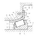
- Longitudinal front view of the tapered roller bearing of the embodiment in the assembled state 1 is a longitudinal front view showing a method for mounting the outer ring of FIG. 1 to a housing. Longitudinal front view showing a modified example of the method of attaching the outer ring to the housing
- FIG. 1 shows a state in which the tapered roller bearing 1 of the embodiment is assembled between the housing 2 and the rotating shaft 3.
- the tapered roller bearing 1 includes an inner ring 4 having a tapered raceway surface 4a on an outer peripheral surface, an outer ring 5 having a tapered raceway surface 5a on an inner peripheral surface, and raceway surfaces 4a of both the raceways 4 and 5.
- 5a a plurality of tapered rollers 6 incorporated between 5a, and a retainer 7 that holds each tapered roller 6 in a rollable manner, and a large flange 8 is provided at the large-diameter side end of the inner ring 4 at the small-diameter side end.
- a gavel 9 is integrally formed so that the tapered roller 6 and the cage 7 do not fall off from the inner ring 4.
- the inner ring 4 is fitted on the outer peripheral surface of the rotating shaft 3, and the outer ring 5 is attached to the inner peripheral surface of the housing 2.
- the outer ring 5 is formed by press working from a hot-rolled steel plate or a cold-rolled steel plate having a constant thickness.
- the material of the steel plate used as the material is one having a carbon content of 0.8 mass% or more, for example, high carbon chromium bearing steel (SUJ2 specified by JIS) or carbon tool steel (SK4, SK5 specified by JIS). ).
- SAJ2 high carbon chromium bearing steel
- SK4 SK5 specified by JIS carbon tool steel
- the reason for selecting this material is that it has excellent wear resistance, which is a necessary property of bearings, has a large distribution volume, is inexpensive in steel materials, and has a high carbon content. (Submerged quenching) provides the same level of hardness distribution as before.
- the outer ring 5 includes a tapered portion 10 whose inner peripheral surface is a raceway surface 5 a, a flange portion 11 that extends radially outward from the large-diameter end of the tapered portion 10, and a small-diameter end of the tapered portion 10. It consists of the straight cylinder part 12 extended in an axial direction.
- the axial cross-sectional shapes of the raceway surface 5a and the outer peripheral surface 10a of the tapered portion 10 are the same as those in FIG. 1, that is, the outer ring 5 is connected to the inner peripheral surface 2a of the housing 2. Is attached to the inner peripheral surface 2a of the housing 2 so as to coincide with the convex axial cross-sectional shape of the tapered surface 2b.
- the outer ring 5 is formed such that the outer diameter on the small diameter side is larger by ⁇ than the inner diameter on the small diameter side of the housing 2 before being attached to the inner peripheral surface 2 a of the housing 2. Then, by pressing the outer ring 5 into the inner periphery of the housing 2 from the state of FIG. 2, the outer ring 5 is attached to the inner peripheral surface 2a of the housing 2 in an elastically deformed state, and the raceway surface 5a of the outer ring 5 as described above.
- the axial sectional shape of the outer peripheral surface 10a of the tapered portion 10 and the axial sectional shape of the tapered surface 2b of the inner periphery of the housing 2 are made to coincide with each other.
- the tapered roller bearing 1 has the above-described configuration, and the axial cross-sectional shape of the raceway surface 5a of the outer ring 5 and the outer peripheral surface 10a of the tapered portion 10 is the tapered surface 2b of the inner periphery of the housing 2 during the bearing operation. Therefore, the deformation of the outer ring 5 is suppressed and the shape of the outer ring raceway surface 5a becomes a crowning shape as intended by the designer. As a result, the surface pressure acting on the outer ring 5 is reduced. Excellent load-carrying performance is obtained by homogenization. In addition, since the outer ring 5 can be formed from a steel plate having a certain thickness only by pressing, it is possible to manufacture the outer ring 5 at a low cost without the need for cutting or grinding during the production of the outer ring.
- the outer ring 5 is pressed into the inner peripheral surface 2a of the housing 2 and attached in an elastically deformed state so that a gap is less likely to be formed between the outer ring 5 and the foreign matter entering or biting into the gap.
- the change of the crowning shape of the outer ring raceway surface 5a due to can be prevented, and the load bearing performance can be stably maintained.
- FIG. 3 shows a modification of the method for attaching the tapered roller bearing 1 to the housing 2.
- a bolt 13 is screwed into the housing 2 through a bolt hole 11 a opened in the flange portion 11 of the outer ring 5.
- the outer ring 5 can be prevented from rotating with respect to the housing 2 and at the same time can be prevented from coming off, so that the tapered roller bearing 1 can be used more stably.
Landscapes
- Engineering & Computer Science (AREA)
- General Engineering & Computer Science (AREA)
- Mechanical Engineering (AREA)
- Rolling Contact Bearings (AREA)
- Mounting Of Bearings Or Others (AREA)
Abstract
外輪を安価に製作でき、かつ耐荷重性能にも優れた円すいころ軸受を提供する。外輪(5)を鋼板からプレス加工によって成形されるものとし、その軌道面(5a)およびその軌道面(5a)を有するテーパ部(10)の外周面(10a)のそれぞれの軸方向断面形状を、外輪(5)をハウジング(2)の内周面(2a)に取り付けたときに、ハウジング(2)内周のテーパ面(2b)の凸形の軸方向断面形状と一致するように形成することにより、軸受運転中には、外輪軌道面(5a)の形状がほぼ設計者の意図通りのクラウニング形状となって、外輪(5)に作用する面圧が均一化され、優れた耐荷重性能が得られるとともに、従来の外輪製作時の切削加工や研削加工が不要となり、外輪(5)の製作コストを低減できるようにしたのである。
Description
本発明は、安価に製造できる円すいころ軸受に関する。
円すいころ軸受は、大きなラジアル荷重とスラスト荷重を同時に支持するのに適した転がり軸受として広く使用されている。その一般的な構造は、外周面にテーパ状の軌道面を有する内輪と、内周面にテーパ状の軌道面を有する外輪と、これらの両軌道輪の軌道面の間に組み込まれる複数の円すいころと、各円すいころを転動自在に保持する保持器とを備え、内輪の大径側端部に大鍔を小径側端部に小鍔を一体形成して、円すいころおよび保持器が内輪から脱落しないようにしている。
このような従来の円すいころ軸受では、外輪を製作する際、通常、鋼材の塊を素材として鍛造加工、切削加工、熱処理および研削加工を順に施しているが、その加工にかかるコストが軸受全体の製造コストを押し上げている。
そこで、本出願人は、外輪を鋼板からプレス加工によって成形されたものとすることにより、従来の外輪製作時の切削加工および研削加工を不要として、外輪の製作コストを低減することを提案した(下記特許文献1参照。)。
また、特許文献1では、鋼板からプレス加工によって成形される外輪の軌道面の軸方向断面形状を凸形(凸曲線状)に形成することにより、軸受運転時に外輪に作用する面圧を均一化して、ころのエッジから受ける面圧を低減し、耐荷重性能の向上を図ることも提案している。なお、このように軌道面ところのエッジとの間の応力集中による過大な接触面圧の発生を避けるために、軌道面の軸方向断面形状を凸形とすることは、一般に「クラウニング」と呼ばれ、その形状は「クラウニング形状」と呼ばれることが多い。
ところで、上記特許文献1に記載の円すいころ軸受は、ハウジングに取り付けられる際に、内周面に軌道面を有する外輪のテーパ部が、ハウジング内周に形成された線形テーパ面に当接するようになっている。このため、上述したように外輪の軌道面をクラウニング形状とする場合に、外輪テーパ部の外周面の軸方向断面形状も軌道面と同様に凸形とすると、軸受運転中にその凸形の外周面がハウジング内周の線形テーパ面に倣うように外輪が変形し、外輪軌道面の形状が設計者の意図したクラウニング形状から外れて、外輪軌道面ところ転動面との間の接触面圧、特にエッジ面圧が過大となり、十分な耐荷重性能が得られなくなるおそれがある。
これに対し、外輪のテーパ部の外周面形状を線形テーパとすれば、軸受運転中の外輪の変形が小さくなって、外輪軌道面の形状はほぼ設計者の意図通りのクラウニング形状となるので、耐荷重性能を確保できる。しかし、このような形状の外輪は、板厚が一定の鋼板からプレス加工で精度よく成形することは難しいので、一定板厚の鋼板をプレス加工した後に切削加工や研削加工して成形することが必要となり、コスト低減効果の小さいものとなってしまう。
そこで、本発明は、外輪を安価に製作でき、かつ耐荷重性能にも優れた円すいころ軸受を提供することを課題とする。
本発明は、上記の課題を解決するために、内輪と外輪のそれぞれのテーパ状の軌道面の間に複数の円すいころを組み込み、これらの各円すいころを保持器で転動自在に保持した円すいころ軸受において、前記外輪が鋼板をプレス加工して成形したものであり、前記外輪の軌道面およびその軌道面を有するテーパ部の外周面のそれぞれの軸方向断面形状は、前記外輪をハウジングの内周面に取り付けたときに、前記ハウジングの内周面に形成されたテーパ面の凸形の軸方向断面形状と一致するように形成した構成を採用した。
上記の構成によれば、軸受運転中の外輪の変形が抑えられ、外輪軌道面の形状がほぼ設計者の意図通りのクラウニング形状となることにより、外輪に作用する面圧が均一化されて耐荷重性能の向上が図れるとともに、外輪を一定板厚の鋼板からプレス加工のみで成形することができるので、従来の外輪製作時の切削加工および研削加工が不要となり、外輪の製作コストを低減できる。
また、前記外輪の小径側外径を前記ハウジングの小径側内径よりも大きく形成して、前記外輪が弾性変形した状態で前記ハウジングの内周面に取り付けられるようにすれば、外輪とハウジングとの間に隙間が生じにくくなるので、その隙間への異物の侵入や噛み込みによる外輪軌道面のクラウニング形状の変化を防止でき、耐荷重性能を安定して維持することができる。
また、前記外輪の素材となる鋼板は、耐摩耗性および熱処理のしやすさの点から、炭素含有量が0.8mass%以上のものとするとよい。
上述したように、本発明の円すいころ軸受は、外輪を鋼板からプレス加工によって成形されるものとし、外輪の軌道面およびその軌道面を有するテーパ部の外周面のそれぞれの軸方向断面形状を、外輪をハウジングの内周面に取り付けたときに、ハウジング内周のテーパ面の凸形の軸方向断面形状と一致するように形成したものであるから、耐荷重性能に優れるとともに、従来の外輪製作時の切削加工や研削加工が不要で、安価に製造することができる。
以下、図面に基づき、本発明の実施形態を説明する。図1は実施形態の円すいころ軸受1をハウジング2と回転軸3の間に組み込んだ状態を示す。この円すいころ軸受1は、外周面にテーパ状の軌道面4aを有する内輪4と、内周面にテーパ状の軌道面5aを有する外輪5と、これらの両軌道輪4、5の軌道面4a、5aの間に組み込まれる複数の円すいころ6と、各円すいころ6を転動自在に保持する保持器7とを備え、内輪4の大径側端部に大鍔8を小径側端部に小鍔9を一体形成して、円すいころ6および保持器7が内輪4から脱落しないようにしたものである。その内輪4は回転軸3の外周面に嵌め込まれ、外輪5はハウジング2の内周面に取り付けられる。
前記外輪5は、板厚が一定の熱間圧延鋼板または冷間圧延鋼板からプレス加工によって成形したものである。その素材となる鋼板の材質は、炭素含有量が0.8mass%以上のもの、例えば、高炭素クロム軸受鋼(JISで規定されるSUJ2)や、炭素工具鋼(JISで規定されるSK4、SK5)としている。この材質の選定理由は、軸受に必要な性質である耐摩耗性に優れていること、流通量が多く鋼材価格が安価なこと、および炭素含有量が多いため、プレス加工後は低コストの熱処理(ずぶ焼入れ)で従来と同水準の硬度分布が得られることにある。
この外輪5は、内周面が軌道面5aとなっているテーパ部10と、テーパ部10の大径側端部から径方向外側に延びるフランジ部11と、テーパ部10の小径側端部から軸方向に延びる直筒部12とからなる。その軌道面5aおよびテーパ部10の外周面10aのそれぞれの軸方向断面形状は、図1の状態で、すなわち外輪5をハウジング2の内周面2a
に取り付けたときに、ハウジング2の内周面2aに形成されたテーパ面2bの凸形の軸方向断面形状と一致するように形成されている。
に取り付けたときに、ハウジング2の内周面2aに形成されたテーパ面2bの凸形の軸方向断面形状と一致するように形成されている。
また、この外輪5は、図2に示すように、ハウジング2の内周面2aに取り付ける前の状態では、小径側外径がハウジング2の小径側内径よりもδだけ大きく形成されている。そして、図2の状態から外輪5をハウジング2の内周に圧入することにより、外輪5が弾性変形した状態でハウジング2の内周面2aに取り付けられ、前述のように外輪5の軌道面5aおよびテーパ部10の外周面10aの軸方向断面形状とハウジング2の内周のテーパ面2bの軸方向断面形状とが一致するようになっている。
この円すいころ軸受1は、上記の構成のものであり、軸受運転中には、外輪5の軌道面5aおよびテーパ部10の外周面10aの軸方向断面形状がハウジング2の内周のテーパ面2bの凸形の軸方向断面形状と一致するので、外輪5の変形が抑えられて外輪軌道面5aの形状がほぼ設計者の意図通りのクラウニング形状となり、その結果、外輪5に作用する面圧が均一化されて優れた耐荷重性能が得られる。しかも、外輪5を一定板厚の鋼板からプレス加工のみで成形できるので、従来の外輪製作時の切削加工や研削加工が不要で、安価に製造することができる。
また、外輪5はハウジング2の内周面2aに圧入されて弾性変形した状態で取り付けられ、ハウジング2との間に隙間が生じにくくなるようにしたので、その隙間への異物の侵入や噛み込みによる外輪軌道面5aのクラウニング形状の変化を防止でき、耐荷重性能を安定して維持することができる。
図3は、円すいころ軸受1のハウジング2への取付方法の変形例を示す。この変形例では、外輪5をハウジング内周面2aに圧入した後、外輪5のフランジ部11にあけたボルト孔11aを通してハウジング2にボルト13をねじ込んでいる。これにより、外輪5をハウジング2に対して廻り止めすると同時に抜け止めすることができるので、円すいころ軸受1をより安定して使用できる。
1 円すいころ軸受
2 ハウジング
2a 内周面
2b テーパ面
3 回転軸
4 内輪
4a 軌道面
5 外輪
5a 軌道面
6 円すいころ
7 保持器
8 大鍔
9 小鍔
10 テーパ部
10a 外周面
11 フランジ部
12 直筒部
13 ボルト
2 ハウジング
2a 内周面
2b テーパ面
3 回転軸
4 内輪
4a 軌道面
5 外輪
5a 軌道面
6 円すいころ
7 保持器
8 大鍔
9 小鍔
10 テーパ部
10a 外周面
11 フランジ部
12 直筒部
13 ボルト
Claims (3)
- 内輪と外輪のそれぞれのテーパ状の軌道面の間に複数の円すいころを組み込み、これらの各円すいころを保持器で転動自在に保持した円すいころ軸受において、
前記外輪が鋼板をプレス加工して成形したものであり、前記外輪の軌道面およびその軌道面を有するテーパ部の外周面のそれぞれの軸方向断面形状が、前記外輪をハウジングの内周面に取り付けたときに、前記ハウジングの内周面に形成されたテーパ面の凸形の軸方向断面形状と一致するように形成されていることを特徴とする円すいころ軸受。 - 前記外輪の小径側外径が前記ハウジングの小径側内径よりも大きく形成され、前記外輪が弾性変形した状態で前記ハウジングの内周面に取り付けられることを特徴とする請求項1に記載の円すいころ軸受。
- 前記外輪の素材となる鋼板は、炭素含有量が0.8mass%以上のものであることを特徴とする請求項1または2に記載の円すいころ軸受。
Applications Claiming Priority (2)
| Application Number | Priority Date | Filing Date | Title |
|---|---|---|---|
| JP2013-196686 | 2013-09-24 | ||
| JP2013196686A JP2015064010A (ja) | 2013-09-24 | 2013-09-24 | 円すいころ軸受 |
Publications (1)
| Publication Number | Publication Date |
|---|---|
| WO2015045798A1 true WO2015045798A1 (ja) | 2015-04-02 |
Family
ID=52742945
Family Applications (1)
| Application Number | Title | Priority Date | Filing Date |
|---|---|---|---|
| PCT/JP2014/073478 Ceased WO2015045798A1 (ja) | 2013-09-24 | 2014-09-05 | 円すいころ軸受 |
Country Status (2)
| Country | Link |
|---|---|
| JP (1) | JP2015064010A (ja) |
| WO (1) | WO2015045798A1 (ja) |
Families Citing this family (1)
| Publication number | Priority date | Publication date | Assignee | Title |
|---|---|---|---|---|
| JP2024080115A (ja) * | 2022-12-01 | 2024-06-13 | 日本トムソン株式会社 | クロスローラ軸受およびクロスローラ軸受の製造方法 |
Citations (2)
| Publication number | Priority date | Publication date | Assignee | Title |
|---|---|---|---|---|
| JP2009024762A (ja) * | 2007-07-19 | 2009-02-05 | Ntn Corp | シェル形ころ軸受の嵌合構造 |
| JP2013036596A (ja) * | 2011-08-11 | 2013-02-21 | Ntn Corp | 円すいころ軸受およびその取付構造 |
-
2013
- 2013-09-24 JP JP2013196686A patent/JP2015064010A/ja active Pending
-
2014
- 2014-09-05 WO PCT/JP2014/073478 patent/WO2015045798A1/ja not_active Ceased
Patent Citations (2)
| Publication number | Priority date | Publication date | Assignee | Title |
|---|---|---|---|---|
| JP2009024762A (ja) * | 2007-07-19 | 2009-02-05 | Ntn Corp | シェル形ころ軸受の嵌合構造 |
| JP2013036596A (ja) * | 2011-08-11 | 2013-02-21 | Ntn Corp | 円すいころ軸受およびその取付構造 |
Also Published As
| Publication number | Publication date |
|---|---|
| JP2015064010A (ja) | 2015-04-09 |
Similar Documents
| Publication | Publication Date | Title |
|---|---|---|
| JP2013036596A (ja) | 円すいころ軸受およびその取付構造 | |
| US9657780B2 (en) | Axial needle roller bearing with self-aligning washers | |
| US10184517B2 (en) | Needle roller bearing with double row of retainers | |
| JP6114556B2 (ja) | 車輪用軸受装置 | |
| JP6019703B2 (ja) | 密封装置付き自動調心ころ軸受及びその製造方法 | |
| US11319994B2 (en) | Thrust roller bearing | |
| CN108700119A (zh) | 车轮用轴承装置和其制造方法 | |
| WO2013011963A1 (ja) | 転がり軸受 | |
| WO2015045798A1 (ja) | 円すいころ軸受 | |
| CN104791380A (zh) | 调心滚子轴承 | |
| JP2012056528A (ja) | 車輪用軸受装置 | |
| US10197094B2 (en) | Double-row spherical roller bearing | |
| JP2007198518A (ja) | ころおよびころ軸受 | |
| JP2007211794A (ja) | 車輪用軸受装置 | |
| JP2010014135A (ja) | バックアップロール用転がり軸受 | |
| JP2014211197A (ja) | シールリング付転がり軸受 | |
| JP2012172812A (ja) | 転がり軸受 | |
| JP2012045577A (ja) | 円錐ころ軸受の外輪の製造方法 | |
| JP2013166487A (ja) | 車輪用軸受装置 | |
| JP2014214844A (ja) | 円すいころ軸受 | |
| JP2008261458A (ja) | 円すいころ軸受 | |
| US8393801B2 (en) | Outer ring of tapered roller bearing and tapered roller bearing | |
| JP7517086B2 (ja) | スラストころ軸受 | |
| JP2009257375A (ja) | 車輪用軸受装置 | |
| JP2013015201A (ja) | 円すいころ軸受 |
Legal Events
| Date | Code | Title | Description |
|---|---|---|---|
| 121 | Ep: the epo has been informed by wipo that ep was designated in this application |
Ref document number: 14848003 Country of ref document: EP Kind code of ref document: A1 |
|
| NENP | Non-entry into the national phase |
Ref country code: DE |
|
| 122 | Ep: pct application non-entry in european phase |
Ref document number: 14848003 Country of ref document: EP Kind code of ref document: A1 |