WO2015037660A1 - Barrage pour réservoir de carburant et procédé de fermeture - Google Patents
Barrage pour réservoir de carburant et procédé de fermeture Download PDFInfo
- Publication number
- WO2015037660A1 WO2015037660A1 PCT/JP2014/074066 JP2014074066W WO2015037660A1 WO 2015037660 A1 WO2015037660 A1 WO 2015037660A1 JP 2014074066 W JP2014074066 W JP 2014074066W WO 2015037660 A1 WO2015037660 A1 WO 2015037660A1
- Authority
- WO
- WIPO (PCT)
- Prior art keywords
- fuel tank
- elastic member
- structural component
- dam
- extending
- Prior art date
Links
Images


Classifications
-
- B—PERFORMING OPERATIONS; TRANSPORTING
- B64—AIRCRAFT; AVIATION; COSMONAUTICS
- B64D—EQUIPMENT FOR FITTING IN OR TO AIRCRAFT; FLIGHT SUITS; PARACHUTES; ARRANGEMENTS OR MOUNTING OF POWER PLANTS OR PROPULSION TRANSMISSIONS IN AIRCRAFT
- B64D37/00—Arrangements in connection with fuel supply for power plant
- B64D37/02—Tanks
- B64D37/06—Constructional adaptations thereof
- B64D37/08—Internal partitioning
-
- B—PERFORMING OPERATIONS; TRANSPORTING
- B64—AIRCRAFT; AVIATION; COSMONAUTICS
- B64C—AEROPLANES; HELICOPTERS
- B64C3/00—Wings
- B64C3/34—Tanks constructed integrally with wings, e.g. for fuel or water
Definitions
- the present invention relates to a fuel tank dam and a closing method.
- a fuel tank is provided on a wing or the like.
- the fuel tank is formed by a plurality of structural components that constitute a main wing or the like.
- a fuel tank dam may be disposed between a plurality of structural components in order to close a gap.
- Sheet metal parts may be used as a fuel tank dam.
- the shapes of a plurality of structural parts constituting an aircraft often have complicated shapes in order to secure structural strength while suppressing an increase in weight.
- the shape of the fuel tank dam also tends to be a complicated shape.
- a fuel dam is disclosed in Patent Document 1 (US Patent No. US8167245).
- the fuel dam comprises a sealing dam member.
- the sealing dam member has a first portion connected to the first body, a second portion connected to the first portion and being more flexible than the first portion, and a third portion connected to the second portion and the second body have.
- the second portion is bent to match the offset of the first body and the second body.
- Patent Document 2 Japanese Patent Laid-Open No. 2006-153624 discloses a leak test plug for closing a rib opening formed in a rib in a wing when detecting a leak of a wing fuel tank of an aircraft. ing.
- the leak test plug includes a base and a locking means fixed to the base and engaged with the rib opening, the fitting member for fitting the base to the rib opening from one side of the rib opening, and the rib
- a pressing member disposed opposite to the fitting member on the other side of the rib opening sandwiching, a pressing member extending to the periphery of the rib opening, a sealing member disposed so as to abut the pressing member, and compressively deformed, the fitting member And connecting means for connecting the pressure member and the pressing member.
- the fitting member is locked to and supported by the rib by the locking means.
- the sealing member is pressed and deformed by the pressing member to close the gap formed between the fitting member and the rib opening.
- patent document 3 International Publication WO2011 / 145291.
- Fuel tank dams are required to have high sealing performance. Then, the subject of this invention is providing the dam for fuel tanks which can improve sealing performance more, and the obstruction
- a fuel tank dam is a fuel tank dam that closes a gap formed between a first structural component and a second structural component.
- the fuel tank dam is supported by the first portion at the first structural portion, the second portion at the second structural portion, and the first portion at one end, and the second portion at the other end.
- an elastic member closing the gap formed between the first portion and the second portion, and a seal mechanism sealing between the first portion and the elastic member.
- a closing method includes the step of closing the gap formed between the first structural component and the second structural component used for the fuel tank with a fuel tank dam.
- the fuel tank dam is supported by the first portion at the first structural component side, the second portion at the second structural component side, and the first portion at one end, and the second portion at the other end.
- An elastic member supported and closing a gap formed between the first portion and the second portion, and a seal mechanism sealing between the first portion and the elastic member.
- the step of closing comprises disposing the first portion on the first structural component and disposing the second portion on the second structural component.
- the fuel tank dam according to another embodiment of the present invention is configured to contact the first structural component used for the fuel tank at one end, and contact the second structural component used for the fuel tank at the other end.
- the elastic member, a first fastening member for fastening one end of the elastic member and the first structural component, and a second fastening member for fastening the other end of the elastic member and the second structural component are provided.
- the elastic member is arranged to close a gap between the first structural component and the second structural component.
- a fuel tank dam includes a first resin member joined to a first structural component used for the fuel tank and a second resin joined to a second structural component used for the fuel tank A member and an elastic member embedded in the first resin member at one end and embedded in the second resin member at the other end.
- the elastic member is arranged to close a gap between the first structural component and the second structural component.
- a fuel tank dam according to still another embodiment of the present invention is an elastic member joined at one end to a first structural component used for a fuel tank, and joined at the other end to a second structural component used for a fuel tank Equipped with The elastic member is arranged to close a gap between the first structural component and the second structural component.
- the elastic member includes a plurality of folded portions provided between one end and the other end.
- a fuel tank dam and a closing method are provided which can improve sealing performance.
- FIG. 1 is a schematic view showing a main wing of an aircraft.
- FIG. 2A is a view when a part of the rib is viewed from the front.
- FIG. 2B is a view showing an AA cross section of FIG. 2A.
- FIG. 3 is a perspective view showing a fuel tank dam according to the first embodiment.
- FIG. 4 is a front view showing a fuel tank dam.
- FIG. 5 is a schematic view showing a sealing mechanism.
- FIG. 6 is a schematic view showing a seal mechanism portion according to a modification of the first embodiment.
- FIG. 7 is a schematic view showing a sealing mechanism according to a second embodiment.
- FIG. 8 is a schematic view showing a sealing mechanism according to a third embodiment.
- FIG. 9 is a schematic view showing a sealing mechanism according to a fourth embodiment.
- FIG. 10 is a schematic view showing a sealing mechanism according to a fifth embodiment.
- FIG. 11 is a schematic view showing a sealing mechanism according to a sixth embodiment.
- FIG. 12 is a schematic view showing a sealing mechanism according to a seventh embodiment.
- FIG. 13 is a schematic view showing a sealing mechanism according to an eighth embodiment.
- FIG. 14 is a schematic view showing a sealing mechanism according to a ninth embodiment.
- FIG. 15 is a schematic view showing a sealing mechanism according to a tenth embodiment.
- FIG. 16 is a schematic view showing a sealing mechanism according to an eleventh embodiment.
- FIG. 17 is a perspective view schematically showing an example of a stringer and an adapter.
- FIG. 18 is a front view showing the stringer after the adapter is placed.
- FIG. 19 is a front view showing the stringer after the fuel tank dam is joined.
- FIG. 20 is a view showing the arrangement of the fuel tank dam 7 in the case of using a J-section stringer.
- FIG. 21 is a view showing the arrangement of a fuel tank dam when a hat stringer is used.
- FIG. 22 is a perspective view schematically showing an adapter according to a modification.
- FIG. 23 is a cross-sectional view schematically showing a fuel tank dam according to a thirteenth embodiment.
- FIG. 24 is a cross-sectional view schematically showing a fuel tank dam according to a fourteenth embodiment.
- FIG. 25 is a schematic view showing a connection portion between the elastic member and the first resin member in the first modification of the fourteenth embodiment.
- FIG. 26 is a schematic view showing a connection portion between the elastic member and the first resin member in the modification 2 of the fourteenth embodiment.
- FIG. 27A is a perspective view schematically showing a fuel tank dam according to a fifteenth embodiment.
- FIG. 27B is a cross-sectional view schematically showing a fuel tank dam.
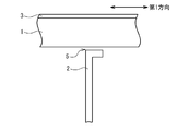
- FIG. 1 is a schematic view showing a main wing 70 of an aircraft. As shown in FIG. 1, the outer shape of the main wing 70 is defined by the skin 3. In the main wing 70, fuel tanks 61 (61-1, 61-2) are provided. Further, a rib 2 is provided in the main wing 70, and the fuel tank 61-1 and the fuel tank 61-2 are divided by the rib 2.
- FIG. 2A is a front view of a part of the joint between the rib 2 and the skin 3.
- FIG. 2B is a figure which shows AA cross section of FIG. 2A.
- a stringer 1 is joined to the skin 3 in order to increase its strength.
- the stringer 1 extends along the first direction (longitudinal direction of the main wing 70) (see FIG. 2B).
- the rib 2 is disposed along a plane perpendicular to the first direction. Further, at the end of the rib 2, a notch 5 is provided. The stringer 1 is disposed to pass through the notch 5.
- a gap 4 is formed.
- the fuel tank dam according to the present embodiment is used to close the gap 4.
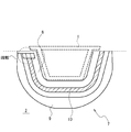
- FIG. 3 is a perspective view showing the fuel tank dam 7.
- FIG. 4 is a front view showing the fuel tank dam 7 and is a view of the fuel tank dam 7 as viewed from the direction along the first direction.
- the outer shapes of the stringer 1 and the rib 2 are shown by dotted lines for reference.
- the fuel tank dam 7 has a first portion 8, a second portion 9, an elastic member 10, and a seal mechanism 13 (13-1, 13-2).
- the first portion 8 is a portion to be fixed (joined) to the stringer 1.
- the second portion 9 is a portion fixed (bonded) to the rib 2.
- the elastic member 10 is supported by being pinched by the first portion 8 at one end, and is supported by being pinched by the second portion 9 at the other end.
- the elastic member 10 closes the gap formed between the first portion 8 and the second portion 9.
- the sealing mechanism 13-1 seals between the first portion 8 and the elastic member 10.
- the sealing mechanism 13-2 seals between the second portion 9 and the elastic member 10.
- the fuel tank dam 7 is fixed to the stringer 1 so as to cover the stringer 1 at the first portion 8 as shown in FIG.
- the first portion 8 is adhered to the stringer 1 via, for example, a sealant.
- the second portion 9 is fixed to the rib 2.
- the second portion 9 is also adhered to the rib 2 via, for example, a sealant.
- between the first portion 8 and the second portion 9 is closed by the elastic member 10.
- the gap 4 between the stringer 1 and the rib 2 is closed.
- Each structural part (stringer 1, rib 2) may be deformed. As a result of the deformation, a load is applied to the fuel tank dam 7. Due to the load, the joint surface between the fuel tank dam 7 and each structural component (stringer 1, rib 2) may be broken. However, according to the configuration as described above, since the elastic member 10 is provided between the first portion 8 and the second portion 9, the load applied to the fuel tank dam 7 is absorbed, and the joint surface is broken. Is prevented.
- the fuel tank dam 7 is provided with a sealing mechanism 13-1.
- the sealability between the elastic member 10 and the first portion 8 is enhanced as compared with the case where the elastic member 10 is simply sandwiched by the first portion 8.
- the sealability between the elastic member 10 and the second portion 9 is further enhanced.
- the first portion 8 is bent so as to cover the stringer 1 when viewed from the front, as shown in FIG. Further, as shown in FIG. 3, the first portion 8 includes a first member 11-1 and a second member 12-1.
- the first member 11-1 is a portion joined to the stringer 1 at the lower surface, and is generally plate-like.
- the second member 12-1 is disposed on the upper surface of the first member 11-1 and has a substantially plate shape.
- the first member 11-1 and the second member 12-1 are joined, for example, via a sealant.
- the first member 11-1 and the second member 12-1 support the elastic member 10 by sandwiching one end of the elastic member 10.
- the second portion 9 is shaped so as to surround the first portion 8 through a gap closed by the elastic member 10 when viewed from the front.
- the second portion 9 also has a first member 11-2 and a second member 12-2 in the same manner as the first portion 8.
- the first member 11-2 is generally plate-shaped, and is joined to the rib 2 at the lower surface.
- the second member 12-2 is also substantially plate-shaped, and is disposed on the first member 11-2.
- the other end of the elastic member 10 is sandwiched and supported by the first member 11-2 and the second member 12-2.
- the first member 11-1 and the first member 11-2 are continuous at an end (see FIG. 4) when viewed from the front, and are one member as a whole.
- the second member 12-1 and the second member 12-2 are continuous at the end when viewed from the front, and are one member as a whole. That is, the fuel tank dam 7 has a structure in which the elastic member 10 is sandwiched between the first member 11 (11-1, 11-2) and the second member 12 (12-1, 12-2). It has a three-layer structure.
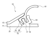
- FIG. 5 is a schematic view showing the sealing mechanism 13 (13-1, 13-2).
- the seal mechanism 13-1 is formed of one end of the elastic member 10 and a part of the first portion 8.
- the sealing mechanism 13-2 is formed by the other end of the elastic member 10 and a part of the second portion 9.
- the seal mechanism 13-1 has a lip seal portion 15-1 provided at one end of the elastic member 10.
- the lip seal portion 15-1 includes a first lip seal portion 19-1 and a second lip seal portion 20-1.
- the first lip seal portion 19-1 and the second lip seal portion 20-1 sandwich a part of the first portion 8.
- the seal mechanism 13-1 includes the pressing portion 14-1, the first extending portion 16-1, the second extending portion 17-1, and the third extension.
- a section 18-1 is provided.
- the pressing portion 14-1 is a part of the first member 11-1, and protrudes from the upper surface (the surface opposite to the bonding surface with the stringer 1) of the first member 11-1 toward the second portion. Is growing.
- the first extending portion 16-1 is provided to the second member 12-1.
- the second member 12-1 is provided with a portion (contact portion 21-1) in contact with the first member 11-1.
- the first extending portion 16-1 extends from an end of the contact portion 21-1 so that a space is formed between the first extending portion 16-1 and the first member 11-1 (specifically, the pressing portion 14-1). There is. Specifically, the first extending portion 16-1 extends so as to face the first member 11-1 (the pressing portion 14-1).
- the second extending portion 17-1 extends from the first extending portion 16-1 in the direction of the first member 11-1 (the pressing portion 14-1).
- the first lip seal portion 19-1 and the second lip seal portion 20-1 described above sandwich the second extending portion 17-1.
- the third extending portion 18-1 extends in the direction from the first extending portion 16-1 toward the first member 11-1 on the tip end side of the second extending portion 17-1.
- One end of the elastic member 10 (the root portion of the lip seal portion 15-1) is sandwiched and supported by the third extending portion 18-1 and the pressing portion 14-1.
- the third extension 18-1 does not have to be provided.
- the sealing mechanism 13-2 also has the same configuration as the sealing mechanism 13-1. That is, the sealing mechanism 13-2 includes the lip seal portion 15-2, the pressing portion 14-2, the first extending portion 16-2, the second extending portion 17-2, and the third extending portion 18-2.
- the second member 12-2 is provided with a contact portion 21-2, and the first extension portion 16-2 is connected to the first member 11-2 (pressing portion 14-2) from the contact portion 21-2. Extends to form a space between the
- the lip seal portion 15-2 has a first lip seal portion 19-2 and a second lip seal portion 20-2.
- the second extension 17-2 is sandwiched by the first lip seal portion 19-2 and the second lip seal portion 20-2.
- the third extending portion 18-2 and the pressing portion 14-2 sandwich and support the other end of the elastic member 10.
- the lip seal portion 15 sandwiches the second extending portion 17 (17-1, 17-2), so high sealing performance can be achieved. You can get it.
- the fuel tank dam 7 may be disposed, for example, at the boundary between fuel tanks. In such a case, a pressure difference may occur on both sides of the fuel tank dam 7. As a result, a force may be applied to the elastic member 10 in such a direction as to peel off the sealing surface.
- the lip seal portions 15 (15-1, 15-2) sandwich the second extending portions 17 (17-1, 17-2).
- the second extending portion 17 (17-1 and 17-) is provided in one of the first lip seal portion 19 (19-1 and 19-2) and the second lip seal portion 20 (20-1 and 20-2). Even when a force causing peeling from 2) is applied, the other lip seal portion exerts a force to push it to the second extending portion 17 (17-1, 17-2) side. Become. Therefore, the sealing function can be maintained regardless of the pressure difference on both sides of the fuel tank dam 7.
- a sealant adheresive or the like between the elastic member 10 and the first portion 8 (or the second portion 9) in order to realize the sealing function.
- a sealant may be applied between the end of the elastic member 10 and the first portion 8 (or the second portion 9).
- the inside of the fuel tank may be contaminated.
- the lip seal portions 15 (15-1, 15-2) are provided, the sealing function can be realized without using the sealant, and the fuel tank can be prevented from being contaminated. .
- a rubber material can be used as the elastic member 10.
- the rubber material for example, fluorosilicone rubber, NBR (Nitrile butadiene rubber), hydrin rubber, hydrogenated nitrile rubber, and other general rubbers can be used.
- first member 11 11-1, 11-2) and the second member 12 (12-1, 12-2)
- a plastic material can be used as the first member 11 (11-1, 11-2) and the second member 12 (12-1, 12-2).
- plastic material nylon, ultra high molecular weight polyethylene, polyacetal, etc. can be used, for example.
- polysulfide-based sealants and other common sealants can be used as the sealant used between each member or part.
- the first extending portions 16 (16-1, 16-2) and the second extending portions 17 (17-1, 17) are provided on the second member 12 (12-1, 12-2) side. -2), and the case where the third extending portion 18 (18-1, 18-2) is provided.
- these configurations may be provided not on the second member 12 (12-1 and 12-2) side but on the first member 11 (11-1 and 11-2) side.
- the first extending portions 16 (16-1, 16-2) and the second extending portions 17 (17-1, 17-) are provided on the first member 11 (11-1, 11-2) side.
- An example in which 2) and third extending portions 18 (18-1 and 18-2) are provided will be described.
- FIG. 6 is a schematic view showing the seal mechanism 13 of the fuel tank dam according to the present modification.
- the sealing mechanisms 13-1 and 13-2 will be described as the sealing mechanism 13 without distinction between the sealing mechanisms 13-1 and 13-2 for the sake of simplicity.
- the first extending portion 16, the second extending portion 17, and the third extending portion 18 are provided not on the second member 12 but on the first member 11 side. It is done.
- the first extending portion 16 extends from the contact portion (contact portion 21) of the first member 11 with the second member 12 so as to face the second member 12. A space is formed between the first extending portion 16 and the second member 12.
- the second extending portion 17 extends in the direction of the second member 12 from the first extending portion 16. As in the previously described embodiment, the first lip seal portion 19 and the second lip seal portion 20 sandwich the second extension portion 17.
- the third extending portion 18 extends from the first extending portion 16 toward the second member 12 on the tip end side of the second extending portion 17.
- the end of the elastic member 10 is sandwiched and supported by the third extension 18 and the second member 12.
- FIG. 7 is a schematic view showing a sealing mechanism 13 according to the present embodiment.
- the sealing mechanism 13 includes a first extending portion 16 and a second extending portion 17.
- the third extending portion 18 (see FIG. 5) is not provided.
- the first lip seal portion 19 and the second lip seal portion 20 sandwich the second extension portion 17.
- the elastic member 10 is sandwiched and supported by the second extending portion 17 and the first member 11 between the first lip seal portion 19 and the second lip seal portion 20.
- the first extending portion 16 and the second extending portion 17 are provided not on the second member 12 side but on the first member 11 side. It may be done.
- FIG. 8 is a schematic view showing a sealing mechanism 13 according to the present embodiment. As shown in FIG. 8, in the present embodiment, a support 22 is added to the sealing mechanism 13.
- the first lip seal portion 19 is disposed inward of the second extending portion 17 in the space 24 formed between the first extending portion 16 and the first member 11.
- the second lip seal portion 20 is disposed outside the second extension portion 17 and sandwiches the second extension portion 17 with the first lip seal portion 19.
- the support 22 is a part of the elastic member 10.
- the support 22 is disposed between the first lip seal portion 19 and the wall of the space 24.
- the first lip seal portion 19 is pressed against the second extending portion 17 by the support portion 22.
- the distance between the first lip seal portion 19 and the second extension portion 17 can be increased. It can be sealed reliably. As a result, the first lip seal portion 19 is less likely to peel off from the second extending portion 17, and the sealing performance is further enhanced.
- the first extending portion 16 and the second extending portion 17 are provided not on the second member 12 side but on the first member 11 side. It may be done.
- the third extending portion 18 may be added also in the present embodiment.
- FIG. 9 is a schematic view showing a sealing mechanism 13 according to the present embodiment.
- the second lip seal portion 20 (see FIG. 8) is omitted from the third embodiment. That is, the elastic member 10 is provided with the seal portion 23 (corresponding to the first lip seal portion 19 in the third embodiment) and the support portion 22.
- the seal portion 23 and the support portion 22 are disposed inside the second extending portion 17 in the space 24 between the first extending portion 16 and the first member 11.
- the support 22 is disposed between the seal 23 and the wall of the space 24 so that the seal 23 is pressed against the second extension 17.
- the support portion 22 is provided, so that the seal portion 23 can be pressed against the second extension portion 17. Therefore, even if the second lip seal portion 20 does not exist, it is possible to enhance the sealing performance.
- the first extending portion 16 and the second extending portion 17 are provided not on the second member 12 side but on the first member 11 side. It may be done.
- the third extending portion 18 may be added also in the present embodiment.
- the fifth embodiment will be described next.
- the configuration of the support portion 22 is changed from the third embodiment.
- the same composition as a 3rd embodiment can be adopted, it omits about detailed explanation.
- FIG. 10 is a schematic view showing a sealing mechanism 13 according to the present embodiment.
- the support portion 22 has a support member 25 provided separately from the elastic member 10.
- the support member 25 is disposed in the space 24.
- the support member 25 is, for example, an elastic body such as rubber.
- the support member 25 is disposed between the first lip seal portion 19 and the wall of the space 24 so that the first lip seal portion 19 is pressed against the second extension portion 17.
- the first extending portion 16 and the second extending portion 17 are provided not on the second member 12 side but on the first member 11 side. It may be done.
- the third extending portion 18 may be added also in the present embodiment.
- the second lip seal portion 20 may be eliminated.
- FIG. 11 is a schematic view showing a sealing mechanism 13 according to the present embodiment.
- the support portion 22 has a sealant portion 26 configured of, for example, a curable sealant.
- the sealant portion 26 is filled between the first lip seal portion 19 and the wall of the space 24. Thereby, the first lip seal portion 19 is pressed against the second extending portion 17.
- the first extending portion 16 and the second extending portion 17 are provided not on the second member 12 side but on the first member 11 side. It may be done.
- the third extending portion 18 may be added also in the present embodiment.
- the second lip seal portion 20 may be eliminated.
- FIG. 12 is a schematic view showing a sealing mechanism 13 according to the present embodiment.
- the sealing mechanism 13 has a first extending portion 16, a second extending portion 17, and a compression portion 27.
- the first extending portion 16 is provided to the second member 12.
- the first extension portion 16 extends from a contact portion (contact portion 21) with the first member 11 so that a space 24 is formed between the first extension portion 16 and the first member 11.
- the second extending portion 17 extends from the first extending portion 16 toward the first member 11.
- the compression portion 27 is provided at one end of the elastic member 10 and bulges more than the other portions of the elastic member 10. The compression portion 27 is compressed by being pinched by the extension portion 16 and the first member 11.
- the compression portion 27 since the compression portion 27 is provided, the sealability between the elastic member 10 and each portion (the first portion 8 and the second portion 9) can be enhanced, and a fuel tank dam The sealability of 7 can be enhanced.
- the first extending portion 16 and the second extending portion 17 are provided not on the second member 12 side but on the first member 11 side. It may be done.
- FIG. 13 is a schematic view showing a sealing mechanism 13 according to the present embodiment.
- the sealing mechanism 13 has a first extending portion 16, a second extending portion 17, and a compression member 28.
- the first extending portion 16 is provided to the second member 12.
- the first extension portion 16 extends from a contact portion (contact portion 21) with the first member 11 so that a space 24 is formed between the first extension portion 16 and the first member 11.
- the second extending portion 17 extends from the first extending portion 16 toward the first member 11.
- the compression member 28 is configured by, for example, a part of a rubber O-ring or the like, and is disposed in the space 24. Further, one end of the elastic member 10 is disposed in the space 24. The compression member 28 is compressed and disposed between one end of the elastic member 10 and the first extension portion 16. One end of the elastic member 10 is sandwiched between the first member 11 and the second member 12 via the compression member 28.
- the first extending portion 16 and the second extending portion 17 are provided not on the second member 12 side but on the first member 11 side. It may be done.
- FIG. 14 is a schematic view showing a sealing mechanism 13 according to the present embodiment.
- the sealing mechanism 13 has a recess 29, a recess 30, a first sealant portion 31, and a second sealant portion 32.
- the recess 30 is provided on the upper surface of the first member 11.
- the recess 29 is provided on the lower surface of the second member 12.
- the recessed portion 30 and the recessed portion 29 are both provided in the portion sandwiching the elastic member 10.
- the first sealant portion 31 is filled in the recess 30.
- the first sealant portion 31 seals the space between the elastic member 10 and the first member 11.
- the second sealant portion 32 is filled in the recess 29.
- the second sealant portion 32 seals between the elastic member 10 and the second member 12.
- the elastic member 10 and each portion are sealed at two points of the first sealant portion 31 and the second sealant portion 32. Therefore, the sealability of the fuel tank dam 7 can be enhanced.
- sealant used for the first sealant portion 31 and the second sealant portion 32 a curable or non-curable sealant is used.
- the sealant described in the first embodiment can be used as a material for forming each sealant portion (31, 32).
- FIG. 15 is a schematic view showing a sealing mechanism 13 according to the present embodiment.
- the seal mechanism 13 has a labyrinth seal structure 33.
- the labyrinth seal structure 33 is formed by the shapes of the respective portions (the first portion 8 and the second portion 9) and the end portion of the elastic member 10.
- the labyrinth seal structure 33 includes an uneven structure provided on the upper surface of the first member 11, an uneven structure provided on the lower surface of the second member 12, and an uneven structure provided on the end of the elastic member 10. have.
- the concavo-convex structure provided in the elastic member 10 is fitted into the concavo-convex structure provided in the first member 11 and the second member 12.
- a sealant 71 is filled between the concavo-convex structure of the elastic member 10 and the concavo-convex structure of the first member 11 and the second member 12.
- the labyrinth seal structure 33 is provided, the sealability between the elastic member 10 and each portion (the first portion 8 and the second portion 9) is enhanced. Thus, the sealability of the fuel tank dam 7 can be enhanced.
- FIG. 16 is a schematic view showing a sealing mechanism 13 according to the present embodiment.
- the sealing mechanism 13 includes a first member extending portion 36, a first member holding portion 37, a second member extending portion 34, a second member holding portion 35, a first lip seal portion 72, and a second lip seal portion 73. Have.
- the first member extension portion 36 is provided to the first member 11.
- the first member 11 is provided with a portion (first member contact portion 21-1) in contact with the second member 12, and the first member extension portion 36 is provided from the first member contact portion 21-1 , And the second member 12 so that a space 38 is formed.
- the first member pinching portion 37 extends from the first member extension portion 36 toward the second member 12 side.
- the second member extension 34 is provided on the second member 12.
- the second member 12 is provided with a portion (second member contact portion 21-2) in contact with the first member 11.
- the second member extension portion 34 is provided from the second member contact portion 21-2,
- the space 38 is extended so as to be formed between the first member 11 and the first member 11.
- the second member extension 34 extends to face the first member extension 36.
- the second member pinching portion 35 extends from the second member extension portion 34 toward the first member 11 side.
- the elastic member 10 is held by the first member holding portion 37 and the second member holding portion 35.
- the first lip seal portion 72 and the second lip seal portion 73 are respectively provided on the elastic member 10.
- the first lip seal portion 72 and the second lip seal portion 73 are disposed in the space 38.
- the first lip seal portion 72 is pressed against the first member 11 (the first member extension portion 36) in the space 38.
- the second lip seal portion 73 is pressed against the second member 12 (second member extension portion 34) in the space 38.
- the first lip seal portion 72 seals the space between the elastic member 10 and the first member 11. Further, the second lip seal portion 73 seals between the elastic member 10 and the second member 12. Since the seal portion is formed in two places, the sealability of the fuel tank dam 7 can be enhanced.
- the other lip seal portion Even when a force is applied in such a direction as to cause one of the first lip seal portion 72 and the second lip seal portion 73 to peel off due to a pressure difference, the other lip seal portion The force is applied to press the first member 11 or the second member 12 side. Therefore, the sealing function can be maintained regardless of the pressure difference on both sides of the fuel tank dam 7.
- an adapter is first disposed on the stringer 1.
- the adapter is used to fill the gap formed between the stringer 1 and the fuel tank dam 7. That is, the adapter is arranged to make the outer shape of the stringer 1 conform to the fuel tank dam 7. Thereafter, the fuel tank dam 7 is fixed to the stringer 1 such that the first portion 8 covers the stringer 1 via the adapter.
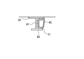
- FIG. 17 is a perspective view schematically showing an example of the stringer 1 and the adapter 42. As shown in FIG. The stringer 1 shown in FIG. 17 is a so-called I cross-sectional stringer.
- the stringer 1 includes a first flat plate portion 39, a second flat plate portion 40, and a connecting portion 41.
- the first flat plate portion 39 is flat and is a portion to be joined to the skin 3.
- the second flat plate portion 40 is disposed to face the first flat plate portion 39 and is flat.
- the connection portion 41 is a portion that connects the first flat plate portion 39 and the second flat plate portion 40. That is, the connecting portion 41 is connected to the first flat plate portion 39 at one end, and is connected to the second flat plate portion 40 at the other end. Further, the connecting portion 41 extends so as to connect the central portion of the first flat plate portion 39 and the central portion of the second flat plate portion 40 when viewed from the direction along the first direction.
- the connecting portion 41 is flat and perpendicular to the first flat plate portion 39.
- the adapter 42 is disposed to fill the recess formed by the first flat plate portion 39, the second flat plate portion 40, and the connecting portion 41.
- the adapter 42 comprises a face 44, a face 43, a face 45, a face 46 and a face 47.
- the surface 44 is a portion to be joined to the connecting portion 41.
- the surface 43 is a portion to be joined to the first flat plate portion 39.
- the surface 45 is a portion to be joined to the second flat plate portion 40.
- the face 46 connects the end of the face 43 and the end of the face 45.
- the closed surface is formed by the surface 44, the surface 43, the surface 45, and the surface 46.
- the surface 47 is a bottom surface, and is disposed so as to close an area formed by the surface 44, the surface 43, the surface 45, and the surface 46 when viewed from the front.
- FIG. 18 is a front view showing the stringer 1 after the adapter 42 is placed.
- the adapter 42 is joined to the stringer 1 via the sealant 77.
- the adapter 42 and the stringer 1 may be fastened by a fastener instead of the sealant 77.
- the adapter 42 may be joined to the stringer 1 using both the sealant 77 and the fastener.
- the adapter 42 is disposed only in one of the two recesses formed on both sides of the connecting portion 41, but in fact, the two adapters 42 are both recesses. Placed in
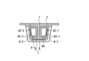
- FIG. 19 is a front view showing the stringer 1 after the fuel tank dam 7 is joined.
- adapters 42-1 and 42-2 are disposed in the stringer 1 such that the first portion 8 covers the stringer 1 via the adapters 42 (42-1, 42-2). That is, the first portion 8 is joined to the second flat plate portion 40 of the stringer 1, the surface 46-1 of the adapter 42-1, and the surface 46-2 of the adapter 42-2.
- a portion 8-1 corresponding to the second flat plate portion 40, a portion 8-2 corresponding to the surface 46-1, and a portion 8-3 corresponding to the surface 46-2 are formed. If it is bent, it does not need complicated shape.
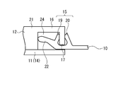
- ⁇ J section stringer> As the stringer 1, a stringer having a shape different from that of the I cross-sectional stringer may be used. Even in such a case, by using the adapter 42, the outer shape of the stringer 1 can be made to correspond to the outer shape of the fuel tank dam 7 (first portion 8). In this example, an example in the case where a J-section stringer is used as the stringer 1 will be described.
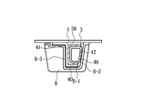
- FIG. 20 is a view showing the arrangement of the fuel tank dam 7 when a J cross section stringer is used as the stringer 1.
- the stringer 1 includes a first flat plate portion 39, a second flat plate portion 40, and a connecting portion 41, as in the example shown in FIG.
- the connecting portion 41 is connected not to the central portion of the second flat plate portion 40 but to the end of the second flat plate portion 40.
- the adapter 42 is disposed only on one side of the connecting portion 41.
- the fuel tank dam 7 As the fuel tank dam 7, the same one as that shown in FIG. 19 can be used. That is, the fuel tank dam 7 is joined to the second flat plate portion 40 at the portion 8-1, joined to the surface 46 of the adapter 42 at the portion 8-2, and joined to the connecting portion 41 at the portion 8-3.
- ⁇ Hat type stringer> As the stringer 1, a hat-type stringer may be used.
- FIG. 21 is a view showing the arrangement of the fuel tank dam 7 when a hat-type stringer is used as the stringer 1.
- the stringer 1 includes a pair of first flat plate portions 74 (74-1 and 74-2), a second flat plate portion 75, and a pair of side portions 76 (76-1 and 76-2). Is equipped.
- the pair of first flat plate portions 74 (74-1 and 74-2) are portions to be joined to the skin 3.
- the second flat plate portion 75 is disposed at a position away from the skin 3 and is parallel to the pair of first flat plate portions 74 (74-1, 74-2).
- the pair of side portions 76 respectively connect the inner end of the pair of flat portions 74 (74-1, 74-2) and the end of the second flat portion 75 doing.
- the pair of side portions (76-1 and 76-2) extend so as to increase in width toward the skin 3 side.
- the fuel tank dam 7 is joined to the second flat plate portion 75 at the portion 8-1, joined to the side portion 76-2 at the portion 8-2, and joined to the side portion 76-1 at the portion 8-3.
- the adapter 42 As described above, according to the present embodiment, by using the adapter 42 as necessary, it is not necessary to create a fuel tank dam 7 having a complicated shape, and the manufacturing cost can be reduced. .
- the fuel tank dam 7 described in the above embodiment does not necessarily have to be used, and has a configuration corresponding to the portions 8-1, 8-2, and 8-3. Then, another fuel tank dam may be used.
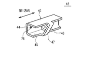
- FIG. 22 is a perspective view schematically showing an adapter 42 according to the present modification.
- each surface (surface 43, surface 44, and surface 45) joined to the stringer 1 is longer than the surface 46 in the first direction.
- the other configuration is the same as that of the adapter 42 shown in FIG.
- the surface 44 is provided with fastener holes 78 for fastening the stringer 1 and the adapter 42 by fasteners. Although sufficient sealability can be secured without fastening the fasteners, fastening may be performed.
- the bonding area between the stringer 1 and the adapter 42 can be increased, and the sealing performance can be further enhanced.
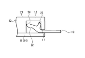
- FIG. 23 is a cross-sectional view schematically showing a fuel tank dam 48 according to the present embodiment.
- the fuel tank dam 48 includes an elastic member 49 and retainer members 50 (50-1, 50-2) made of metal or resin.
- the elastic member 49 is arranged to close the gap between the stringer 1 and the rib 2. Specifically, the elastic member 49 contacts the stringer 1 at one end and contacts the rib 2 at the other end.
- a material of the elastic member 49 the same material as the elastic member 10 described in the first embodiment can be used.
- the retainer member 50-1 is provided at one end of the elastic member 49, and is disposed so as to sandwich the elastic member 49 with the stringer 1.
- the retainer member 50-1 is provided for joining the elastic member 49 to the stringer 1 by the fastener 52-1. That is, the retainer member 50-1, the elastic member 49, and the stringer 1 are fastened by the fastener 52-1.
- the retainer member 50-2 is provided at the other end of the elastic member 49 and sandwiches the elastic member 49 with the rib 2.
- the retainer member 50-2, the elastic member 49, and the rib 2 are fastened by fasteners 52-2.
- the retainer member 50 for example, a plastic material is used.
- the gap between the stringer 1 and the rib 2 is closed by the two-layer structure (the elastic member 49 and the retainer members 50-1 and 50-2). Therefore, the manufacturing cost can be further reduced.
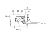
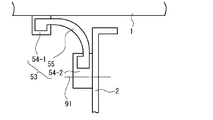
- FIG. 24 is a cross-sectional view schematically showing a fuel tank dam 53 according to the present embodiment.
- the fuel tank dam 53 includes a first resin member 54-1, a second resin member 54-2, and an elastic member 55.
- the second resin member 54-2 and the rib 2 are fastened by a fastener 91.
- the first resin member 54-1 is a portion joined to the stringer 1.
- the second resin member 54-2 is a portion joined to the rib 2.
- the first resin member 54-1 and the second resin member 54-2 are respectively joined to the stringer 1 and the rib 2 via, for example, a sealant.
- the same material as the elastic member 10 described in the first embodiment can be used.
- a rubber material is used.
- the elastic member 55 is embedded in the first resin member 54-1 at one end, and is embedded in the second resin member 54-2 at the other end. The elastic member 55 closes the gap between the stringer 1 and the rib 2.
- the elastic member 55, the first resin member 54-1, and the second resin member 54-2 are integrally joined by integral molding.
- the gap between the stringer 1 and the rib 2 is closed by the two-layer structure (elastic member 49 and resin members 54-1 and 54-2). . Therefore, the manufacturing cost can be further reduced.
- the elastic member 55, the first resin member 54-1, and the second resin member 54-2 are joined by integral molding. Therefore, the sealing performance at the connection portion between the elastic member 55 and the first resin member 54-1 can be enhanced. The same applies to the sealability between the elastic member 55 and the second resin member 54-2.
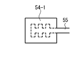
- FIG. 25 is a schematic view showing a connection portion between the elastic member 55 and the first resin member 54-1 in the present modification. As shown in FIG. 25, an uneven structure is provided at one end of the elastic member 55. The first resin member 54-1 covers this uneven structure. Although not shown, the same applies to the joint portion between the other end of the elastic member 55 and the second resin member 54-2.
- the concavo-convex structure since the concavo-convex structure is provided, the adhesion between the elastic member 55 and each of the resin members (54-1, 54-2) can be enhanced. Thereby, the sealability of the fuel tank dam 53 can be enhanced.
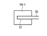
- FIG. 26 is a schematic view showing a connection portion between the elastic member 55 and the first resin member 54-1 in the present modification.
- a surface treatment unit 51 is provided at an end of the elastic member 55.
- the surface treatment unit 51 is a portion subjected to surface treatment to make the surface rough.
- the other end of the elastic member 55 is also the same.
- a satin treatment is used as the surface treatment.
- the surface treatment unit 51 may be provided not on the elastic member 55 side but on the resin member 54 (54-1, 54-2) side. In this case, first, at the time of molding of each resin member 54 (54-1, 54-2), a surface treatment is applied to a portion to be joined with the elastic member 55. Thereafter, the elastic member 55 is molded so as to be embedded in each of the resin members 54 (54-1, 54-2).
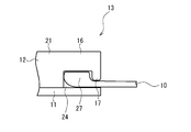
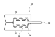
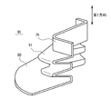
- FIG. 27A is a perspective view schematically showing a fuel tank dam 90 according to the present embodiment.
- FIG. 27B is a cross-sectional view schematically showing the fuel tank dam 90.
- the fuel tank dam 90 includes a first portion 79, a second portion 80, and a third portion 81.
- the first portion 79, the second portion 80, and the third portion 81 are integrally formed of, for example, a plastic material or the like.
- the first portion 79 is a portion joined to the stringer 1.
- the first portion 79 is adhered to the stringer 1 via, for example, a sealant.
- the second portion 80 is a portion joined to the rib 2. Similar to the first portion 79, the second portion 80 is also adhered to the rib 2, for example via a sealant. The second portion 80 is fastened to the rib 2 by a fastener (not shown).
- the third portion 81 is a portion that connects the first portion 79 and the second portion 80, and is provided to close a gap between the first portion 79 and the second portion 80.
- the third portion 81 includes a plurality of folded portions 82. That is, the third portion 81 has a bellows shape.
- the third portion 81 since the third portion 81 has a bellows shape, the load is absorbed by the third portion 81 even when the load is applied by the deformation of the rib 2 or the stringer 1. As a result, breakage of the bonding surface between the fuel tank dam 90 and each structural component (rib 2, stringer 1) can be prevented, and the sealing performance can be enhanced.
- [Item 1] Including a step of closing a gap formed between the first structural component and the second structural component used for the fuel tank with a fuel tank dam;
- the fuel tank dam is A first portion disposed on the first structural component side; A second portion disposed on the second structural component side; An elastic member supported by the first portion at one end and supported by the second portion at the other end to close a gap formed between the first portion and the second portion; A sealing mechanism for sealing between the first portion and the elastic member;
- the step of closing is Placing the first portion on the first structural component; Placing the second portion on the second structural part.
- the first structural component is A first flat plate portion joined to the skin and being flat; A second flat plate portion which is disposed so as to face the first flat plate portion and is in the form of a flat plate; A connecting portion that extends perpendicularly to the first flat plate portion, is connected to the first flat plate portion at one end, and is connected to the second flat plate portion at the other end, The adapter is arranged to fill a recess formed by the first flat plate portion, the second flat plate portion, and the connection portion.
Abstract
Priority Applications (3)
| Application Number | Priority Date | Filing Date | Title |
|---|---|---|---|
| CN201480041349.8A CN105408204B (zh) | 2013-09-11 | 2014-09-11 | 燃料箱用挡板 |
| US14/907,735 US9815562B2 (en) | 2013-09-11 | 2014-09-11 | Fuel tank dam |
| EP14844193.4A EP3012186B1 (fr) | 2013-09-11 | 2014-09-11 | Barrage pour réservoir de carburant et son utilisation |
Applications Claiming Priority (2)
| Application Number | Priority Date | Filing Date | Title |
|---|---|---|---|
| JP2013-188338 | 2013-09-11 | ||
| JP2013188338A JP6381191B2 (ja) | 2013-09-11 | 2013-09-11 | 燃料タンク用ダム |
Publications (1)
| Publication Number | Publication Date |
|---|---|
| WO2015037660A1 true WO2015037660A1 (fr) | 2015-03-19 |
Family
ID=52665760
Family Applications (1)
| Application Number | Title | Priority Date | Filing Date |
|---|---|---|---|
| PCT/JP2014/074066 WO2015037660A1 (fr) | 2013-09-11 | 2014-09-11 | Barrage pour réservoir de carburant et procédé de fermeture |
Country Status (5)
| Country | Link |
|---|---|
| US (1) | US9815562B2 (fr) |
| EP (1) | EP3012186B1 (fr) |
| JP (1) | JP6381191B2 (fr) |
| CN (1) | CN105408204B (fr) |
| WO (1) | WO2015037660A1 (fr) |
Cited By (1)
| Publication number | Priority date | Publication date | Assignee | Title |
|---|---|---|---|---|
| EP3656657A1 (fr) * | 2018-11-26 | 2020-05-27 | Airbus Operations Limited | Étanchéification de l'ouverture d'un réservoir de carburant d'aéronef |
Families Citing this family (6)
| Publication number | Priority date | Publication date | Assignee | Title |
|---|---|---|---|---|
| JP6890968B2 (ja) * | 2016-12-26 | 2021-06-18 | キヤノントッキ株式会社 | 圧力容器 |
| JP7083602B2 (ja) | 2017-07-12 | 2022-06-13 | 三菱重工業株式会社 | 燃料タンク用ダム |
| JP7019528B2 (ja) | 2018-07-20 | 2022-02-15 | 三菱重工業株式会社 | 燃料タンク用ダム |
| CN109305328B (zh) * | 2018-11-12 | 2024-01-16 | 中国商用飞机有限责任公司北京民用飞机技术研究中心 | 一种翼盒及飞机 |
| CN109677586A (zh) * | 2019-01-18 | 2019-04-26 | 中国商用飞机有限责任公司北京民用飞机技术研究中心 | 一种腹板、飞机机翼和飞机 |
| US11787555B2 (en) * | 2021-08-13 | 2023-10-17 | The Boeing Company | Fuel dams, aircraft wing boxes, aircraft, and methods of assembling aircraft wings |
Citations (8)
| Publication number | Priority date | Publication date | Assignee | Title |
|---|---|---|---|---|
| US4556439A (en) * | 1981-09-25 | 1985-12-03 | The Boeing Company | Method of sealing and bonding laminated epoxy plates |
| US20040213953A1 (en) * | 2003-04-24 | 2004-10-28 | Lockheed Martin Corporation | Apparatus, system, and method of joining structural components with a tapered tension bond joint |
| JP2006153624A (ja) | 2004-11-29 | 2006-06-15 | Fuji Heavy Ind Ltd | 漏洩試験用プラグ |
| WO2011145291A1 (fr) | 2010-05-17 | 2011-11-24 | 三菱航空機株式会社 | Élément de fermeture pour ouverture |
| US8167245B1 (en) | 2009-11-03 | 2012-05-01 | The Boeing Company | Fuel barrier |
| JP2012201361A (ja) * | 2011-03-25 | 2012-10-22 | Boeing Co:The | ジョイントシーリングシステム |
| US20120280083A1 (en) * | 2009-11-30 | 2012-11-08 | Airbus Operations (S.A.S.) | Method of making a sealed junction between aircraft parts |
| JP2013188338A (ja) | 2012-03-14 | 2013-09-26 | Daito Giken:Kk | 遊技台 |
Family Cites Families (11)
| Publication number | Priority date | Publication date | Assignee | Title |
|---|---|---|---|---|
| US2552119A (en) * | 1946-04-04 | 1951-05-08 | Goodrich Co B F | Collapsible fuel tank for aircraft |
| FR1580796A (fr) | 1968-09-24 | 1969-09-05 | ||
| AT4282U1 (de) * | 2000-01-26 | 2001-05-25 | Tesma Motoren Getriebetechnik | Treibstoffbehälter für kraftfahrzeuge |
| US7373892B2 (en) * | 2001-02-05 | 2008-05-20 | Veazey Sidney E | Production, transport and use of prefabricated components in shoreline and floating structures |
| US7202321B2 (en) | 2002-06-07 | 2007-04-10 | The Boeing Company | Method and composition for sealing components and components sealed thereby |
| DE10229803B4 (de) * | 2002-07-03 | 2006-07-27 | Eurocopter Deutschland Gmbh | Verbindungsanordnung zur lösbaren Verbindung eines ersten flexiblen Tanks mit einem zweiten flexiblen Tank eines Luftfahrzeugs |
| US8333345B2 (en) * | 2010-08-26 | 2012-12-18 | The Boeing Company | Composite aircraft joint |
| US8689816B2 (en) * | 2011-12-22 | 2014-04-08 | Eaton Corporation | Fuel tank vent valve assembly and method of assembly |
| CN203114105U (zh) * | 2013-01-30 | 2013-08-07 | 湖南省金为型材有限公司 | 一种用于钢制门窗的密封条 |
| US9096324B2 (en) * | 2013-03-19 | 2015-08-04 | The Boeing Company | Joint assembly to form a sealed flow conduit |
| CN103215677B (zh) * | 2013-05-07 | 2016-06-08 | 四川理工学院 | 一种阻尼减振稳心式电锭离心机 |
-
2013
- 2013-09-11 JP JP2013188338A patent/JP6381191B2/ja active Active
-
2014
- 2014-09-11 WO PCT/JP2014/074066 patent/WO2015037660A1/fr active Application Filing
- 2014-09-11 EP EP14844193.4A patent/EP3012186B1/fr active Active
- 2014-09-11 US US14/907,735 patent/US9815562B2/en active Active
- 2014-09-11 CN CN201480041349.8A patent/CN105408204B/zh not_active Expired - Fee Related
Patent Citations (8)
| Publication number | Priority date | Publication date | Assignee | Title |
|---|---|---|---|---|
| US4556439A (en) * | 1981-09-25 | 1985-12-03 | The Boeing Company | Method of sealing and bonding laminated epoxy plates |
| US20040213953A1 (en) * | 2003-04-24 | 2004-10-28 | Lockheed Martin Corporation | Apparatus, system, and method of joining structural components with a tapered tension bond joint |
| JP2006153624A (ja) | 2004-11-29 | 2006-06-15 | Fuji Heavy Ind Ltd | 漏洩試験用プラグ |
| US8167245B1 (en) | 2009-11-03 | 2012-05-01 | The Boeing Company | Fuel barrier |
| US20120280083A1 (en) * | 2009-11-30 | 2012-11-08 | Airbus Operations (S.A.S.) | Method of making a sealed junction between aircraft parts |
| WO2011145291A1 (fr) | 2010-05-17 | 2011-11-24 | 三菱航空機株式会社 | Élément de fermeture pour ouverture |
| JP2012201361A (ja) * | 2011-03-25 | 2012-10-22 | Boeing Co:The | ジョイントシーリングシステム |
| JP2013188338A (ja) | 2012-03-14 | 2013-09-26 | Daito Giken:Kk | 遊技台 |
Cited By (3)
| Publication number | Priority date | Publication date | Assignee | Title |
|---|---|---|---|---|
| EP3656657A1 (fr) * | 2018-11-26 | 2020-05-27 | Airbus Operations Limited | Étanchéification de l'ouverture d'un réservoir de carburant d'aéronef |
| US11420722B2 (en) | 2018-11-26 | 2022-08-23 | Airbus Operations Limited | Aircraft fuel tank aperture sealing |
| US11597498B2 (en) | 2018-11-26 | 2023-03-07 | Airbus Operations Limited | Aircraft fuel tank aperture sealing |
Also Published As
| Publication number | Publication date |
|---|---|
| US20160159490A1 (en) | 2016-06-09 |
| US9815562B2 (en) | 2017-11-14 |
| JP2015054581A (ja) | 2015-03-23 |
| JP6381191B2 (ja) | 2018-08-29 |
| CN105408204A (zh) | 2016-03-16 |
| CN105408204B (zh) | 2017-12-05 |
| EP3012186A1 (fr) | 2016-04-27 |
| EP3012186B1 (fr) | 2017-11-08 |
| EP3012186A4 (fr) | 2016-06-01 |
Similar Documents
| Publication | Publication Date | Title |
|---|---|---|
| WO2015037660A1 (fr) | Barrage pour réservoir de carburant et procédé de fermeture | |
| RU2498911C2 (ru) | Узел герметизированного окна с интегрированным уплотнителем и способ его установки | |
| CA2910867C (fr) | Dispositif d'etancheite pour une vitre fixe de vehicule | |
| WO2008045485A3 (fr) | Combinaison d'attache mécanique réutilisable et de joint hermétique | |
| US10084199B2 (en) | Fuel cell stack enclosure | |
| WO2009129375A3 (fr) | Structures de sac et procédés d'assemblage de ceux-ci | |
| US9630574B2 (en) | Exterior component for a vehicle | |
| US20110045882A1 (en) | Waterproof-type electronic equipment | |
| WO2014061122A1 (fr) | Écrou muni d'une rondelle d'étanchéité | |
| US20170074401A1 (en) | Press-in-place gasket | |
| JP2015054581A5 (fr) | ||
| JP5375657B2 (ja) | 車両用ドア構造 | |
| JP2011502092A (ja) | 2つの中空セクション部品端接続用コネクタ | |
| WO2007016205A3 (fr) | Ensemble joint | |
| JP2015182720A (ja) | センターピラーウエザストリップ | |
| WO2017133585A1 (fr) | Vessie pneumatique en caoutchouc comportant de multiples surfaces incurvées et une ouverture unique | |
| JP5314562B2 (ja) | 開口枠 | |
| JP6171668B2 (ja) | サンルーフのパネル構造 | |
| JP2013141877A (ja) | 車体のパネル構造 | |
| JP5442591B2 (ja) | ガスケットの製造方法 | |
| JPH0858392A (ja) | サンルーフ | |
| JP5564969B2 (ja) | サービスホールのシール構造、発泡材製サービスホールカバー | |
| JP6546025B2 (ja) | 固定窓用シール構造 | |
| JP2017529534A5 (fr) | ||
| JP4717626B2 (ja) | ドアウエザストリップ、その取付構造、及び、その取付方法 |
Legal Events
| Date | Code | Title | Description |
|---|---|---|---|
| WWE | Wipo information: entry into national phase |
Ref document number: 201480041349.8 Country of ref document: CN |
|
| 121 | Ep: the epo has been informed by wipo that ep was designated in this application |
Ref document number: 14844193 Country of ref document: EP Kind code of ref document: A1 |
|
| REEP | Request for entry into the european phase |
Ref document number: 2014844193 Country of ref document: EP |
|
| WWE | Wipo information: entry into national phase |
Ref document number: 2014844193 Country of ref document: EP |
|
| WWE | Wipo information: entry into national phase |
Ref document number: 14907735 Country of ref document: US |
|
| NENP | Non-entry into the national phase |
Ref country code: DE |