WO2015037523A1 - 筐体および表示装置 - Google Patents
筐体および表示装置 Download PDFInfo
- Publication number
- WO2015037523A1 WO2015037523A1 PCT/JP2014/073439 JP2014073439W WO2015037523A1 WO 2015037523 A1 WO2015037523 A1 WO 2015037523A1 JP 2014073439 W JP2014073439 W JP 2014073439W WO 2015037523 A1 WO2015037523 A1 WO 2015037523A1
- Authority
- WO
- WIPO (PCT)
- Prior art keywords
- rib
- cabinet
- front cabinet
- rear cabinet
- wall
- Prior art date
- Legal status (The legal status is an assumption and is not a legal conclusion. Google has not performed a legal analysis and makes no representation as to the accuracy of the status listed.)
- Ceased
Links
Images




Classifications
-
- H—ELECTRICITY
- H04—ELECTRIC COMMUNICATION TECHNIQUE
- H04N—PICTORIAL COMMUNICATION, e.g. TELEVISION
- H04N5/00—Details of television systems
- H04N5/64—Constructional details of receivers, e.g. cabinets or dust covers
Definitions
- the present invention relates to a housing and a display device, and more particularly to a housing and a display device in which a front cabinet and a rear cabinet are connected without using screws.
- a liquid crystal display device such as a thin television has a display module including a liquid crystal panel, an LED (Light Emitting Diode) light source, and the like.
- a front cabinet is provided around the liquid crystal panel, and the back side of the display module is covered with the rear cabinet.
- a structure in which the front cabinet and the rear cabinet are screwed is known.
- a screw fastening region or the like is required, and thus it is difficult to achieve a design that narrows the frame (also referred to as a narrow frame structure).
- Patent Document 1 discloses a technique for fixing cabinets to each other.
- a fixing claw provided on a front cabinet (second cabinet) is provided with a recess ( It is fitted in the concave part.
- JP 2007-81919 A Japanese Patent No. 4360921
- the convex portion is formed toward the thickness portion of the front cabinet and does not extend toward the inner wall of the front cabinet where the display module is disposed. That is, the front cabinet and the rear cabinet cannot be coupled inside the front cabinet, but are coupled outside the inner wall of the front cabinet. For this reason, there is a problem that it is difficult to make the size of the front cabinet and the rear cabinet close to the size of the display module, and it is still difficult to achieve a design that narrows the frame. Further, in the technique described in Patent Document 2, the portion where the recess is formed becomes thin, resulting in insufficient strength, and the first cabinet is expanded outside or the second cabinet is narrowed inward, and then fitted. Therefore, a separate force is required to continue bending the cabinet.
- the present invention has been made in view of the above circumstances, and an object thereof is to provide a housing and a display device that can achieve a design for narrowing a frame without using screws.
- a first technical means of the present invention includes a front cabinet provided around a predetermined object to be stored, and a rear cabinet that covers a back surface of the predetermined object to be stored, A rib portion formed to be disposed on the inner wall of the front cabinet and a claw portion formed on the inner wall of the rear cabinet on the inner side of the rib portion, and an inner wall of the front cabinet And a rib receiving portion that receives the rib portion, and the rib receiving portion is sandwiched between the rib portion and the claw portion.
- the second technical means includes a front cabinet provided around a predetermined object to be stored, and a rear cabinet that covers a back surface of the predetermined object to be stored, and is formed in the front cabinet, and an inner wall of the rear cabinet.
- a rib portion extending so as to be disposed on the inner wall of the front cabinet and a claw portion formed on the inner side of the rib portion; a rib receiving portion formed on the inner wall of the rear cabinet and receiving the rib portion;
- the rib receiving part is sandwiched between the rib part and the claw part.
- the claw portion is formed in an annular shape, and when the front cabinet and the rear cabinet are connected or disassembled, the rib receiving portion It is characterized by bending by contact.
- the rib receiving portion has a tapered surface having a different inclination direction along an attaching / detaching direction of the claw portion.
- the claw portion clamps the rib receiving portion by approaching the rib portion after leaving the rib portion along the tapered surface, and the claw portion and the rib portion.
- the claw part is removed from the clamping position, the claw part is detached from the rib receiving part by moving away from the rib part along the tapered surface and then approaching the rib part.
- a fifth technical means includes any one of the first to fourth technical means, and the predetermined object is a display module.
- the rib receiving portion receives the rib portion with the inner wall of the front cabinet, and the rib receiving portion is supported by being sandwiched between the rib portion and the claw portion formed in the rear cabinet.
- the positioning mechanism of the rear cabinet with respect to the front cabinet can serve as the fixing mechanism of the front cabinet and the rear cabinet.
- a rib receiving part is formed in the inner wall of a front cabinet, these connection can be performed inside a front cabinet and a rear cabinet.
- the size of the front cabinet and the rear cabinet can be easily approximated to the size of the display module, and a design in which the frame between the inner wall of the front cabinet and the end surface of the display module is reduced and the frame is narrowed can be achieved.
- FIG. 3 It is a figure which shows an example of the external appearance of the display apparatus by this invention. It is a figure which shows the state which removed the rear cabinet from the display apparatus shown in FIG. It is a figure which shows an example of the state which decomposed
- FIG. 1 is a diagram showing an example of the appearance of a display device according to the present invention.
- 1A shows a state of the display device viewed from the front
- FIG. 1B shows a state of the display device viewed from the back
- FIG. 1C shows a state of the display device viewed from the left side.
- 1 is a liquid crystal display device
- 2 is a front cabinet
- 3 is a panel module
- 4 is a liquid crystal panel
- 8 is a rear cabinet
- 9 is a stand
- 10 is a cord lead portion
- 11 is a terminal lead portion
- 12 is a slot.
- the liquid crystal panel 4 has a structure in which liquid crystal is sandwiched between two glass substrates, and light emitted from a light guide plate in a panel module described later by controlling the alignment state of liquid crystal molecules forming the liquid crystal. It has a function as an optical shutter that controls transmission / cutoff of light.
- the front cabinet 2 is formed in a resin frame shape, for example, and is provided around the liquid crystal panel 4.
- the resin rear cabinet 8 covers the back side of the panel module 3, and a stand 9 for supporting the liquid crystal display device 1 is attached at the center position.
- the rear cabinet 8 is formed with a cord lead-out portion 10 for drawing out a power cord from the power-supply substrate side, which will be described later, and a terminal lead-out portion 11 for drawing out various connection terminals from the main substrate side.
- An IC card slot 12 to be inserted into the liquid crystal display device 1 is provided on the left side surface of the rear cabinet 8.
- FIG. 2 is a diagram illustrating a state in which the rear cabinet is removed from the display device illustrated in FIG. 1
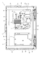
- FIG. 3 is a diagram illustrating an example of a state in which the internal structure of the display device illustrated in FIG. 1 is disassembled.
- the front cabinet 2 forms a frame shape by connecting the upper surface 2a, the left surface 2b, the lower surface 2c, and the right surface 2d, and faces the upper surface 3a, the left surface 3b, the lower surface 3c, and the right surface 3d of the panel module 3, respectively.
- the panel module 3 includes an optical sheet, a light guide plate, a reflection sheet, and the like on the back side of the liquid crystal panel 4, and a back chassis 5 on the back side of the reflection sheet. Note that a combination of the front cabinet and the rear cabinet corresponds to the casing of the present invention, and the panel module corresponds to a predetermined object or display module of the present invention.
- the optical sheet is formed of, for example, two microlens sheets and one brightness enhancement sheet, and has functions such as uniformizing the light emitted from the light guide plate and improving the brightness in the front direction.
- the light guide plate is made of a transparent resin such as acrylic, and emits light from an edge light type LED light source to the liquid crystal panel 4 positioned on the front side, for example.
- the reflection sheet has a function of reflecting light that is not incident on the light guide plate out of the light emitted from the LED light source and entering the light guide plate.
- the rear chassis 5 holds a light guide plate, a reflection sheet, and the like, and functions as a mounting base for them. In a state where the rear cabinet 8 is removed, the rear chassis 5, the power supply board 6, the main board 7, the reinforcing metal fittings 20, 30 and the like can be seen.
- the main board 7 is provided with an external connection terminal 7a, a heat radiating plate 7b, and an IC card cover 7c.
- the reinforcing metal fittings 20 and 30 extend in the vertical direction of the liquid crystal display device 1 and are arranged in the vicinity of both left and right ends of the panel module 3.
- the reinforcing brackets 20 and 30 are made of, for example, a metal such as iron, and connect the upper surface 3a and the lower surface 3c of the panel module 3 to each other.
- the rear cabinet 8 is screwed to the reinforcing metal fittings 20 and 30 at positions corresponding to the reinforcing metal fittings 20 and 30, for example, around the upper corner portion.
- the front cabinet does not have to be provided with a boss for connecting to the rear cabinet, which also contributes to the achievement of a design that narrows the frame.
- FIG. 4 is a diagram showing an example of the structure of the front cabinet and the rear cabinet in FIG. 5 and 6 are diagrams illustrating the assembly of the front cabinet and the rear cabinet of FIG. 3, in which FIG. 5 (A) shows before assembly and FIG. 5 (B) shows after assembly.
- FIG. 6 is a cross-sectional view taken along line VI-VI in FIG.
- the front cabinet 2 and the rear cabinet 8 have a structure that doubles as a positioning mechanism and a fixing mechanism.
- the right side 2d of the front cabinet 2 located on the front side (left side in FIG. 2) of FIG. 3 and the front side of the corresponding rear cabinet 8 will be described as an example.
- a rib portion 51 is formed on the peripheral edge of the rear cabinet 8, and a tip 52 of the rib portion 51 extends so as to be disposed on the inner wall 40 of the right surface 2 d of the front cabinet 2 when assembled.
- a claw portion 53 is formed inside the rib portion 51, and the head 54 of the claw portion 53 extends so as to be disposed on the inner wall 40 of the right surface 2d.
- the base of the claw portion 53 has a curved portion and is integrally formed on the inner wall 50 of the rear cabinet 8 at a position near the rib portion 51.
- a rib receiving portion 41 is formed on the inner wall 40 of the right surface 2d.
- the rib receiving portion 41 has a groove 42 for receiving the rib portion 51, and a mountain-shaped tapered surface 43 is formed inside the groove 42.
- the taper surface 43 has a taper with a different inclination direction along the attachment / detachment direction of the claw portion 53.
- a rib receiving portion is also formed on the upper surface 2a and the left surface 2b of the front cabinet 2, and a rib portion and a claw portion are also formed at corresponding positions of the rear cabinet 8, and can be fixed to each other.
- the leading end 52 of the rib portion 51 fits into the groove 42 of the rib receiving portion 41 from the state of FIG. 4 or FIG.
- the position of the cabinet 8 can be determined.
- the claw portion 53 is bent, and the head 54 moves along the tapered surface 43 in a direction away from the rib portion 51.
- the head 54 climbs over the top portion of the tapered surface 43 and then moves along the tapered surface 43 in a direction approaching the rib portion 51 to reach a predetermined clamping position.
- FIG. 5B and FIG. 6 the rib receiving portion 41 is held between the rib portion 51 and the claw portion 53, and the fixing of the front cabinet 2 and the rear cabinet 8 is completed.
- the rib receiving portion 41 receives the rib portion 51 between the inner wall 40 of the front cabinet 2 and the rib receiving portion 41 is supported by being sandwiched between the rib portion 51 and the claw portion 53 formed in the rear cabinet 8.
- the positioning mechanism of the rear cabinet 8 with respect to the front cabinet 2 and the fixing mechanism of the front cabinet 2 and the rear cabinet 8 can be combined, and can be realized without using screws. Therefore, the number of parts and the number of work steps can be reduced as compared with the case where the front cabinet and the rear cabinet are screwed. Furthermore, since no screws are used, the front cabinet 2 and the rear cabinet 8 combined can be easily disassembled.
- the front cabinet 2 and the rear cabinet 8 can be connected inside the front cabinet 2 and the rear cabinet 8.
- the size of the front cabinet 2 and the rear cabinet 8 can be easily approximated to the size of the panel module 3, the space between the inner wall 40 of the front cabinet 2 and the end surface of the panel module 3 is reduced, and the frame is narrowed. can do.
- FIG. 7 is a diagram showing another example of the structure of the front cabinet and the rear cabinet of FIG.
- the front cabinet has a rib receiving part
- the rear cabinet has a rib part and a nail
- the present invention is not necessarily limited to this form, and the front cabinet may have a rib part and a claw part, and the rear cabinet may have a rib receiving part.
- a rib portion 61 is formed on the peripheral edge of the front cabinet 2, and a tip 62 of the rib portion 61 extends so as to be disposed on the inner wall 50 of the rear cabinet 8 when assembled. Yes. Further, a claw portion 63 is formed inside the rib portion 61, and the head 64 of the claw portion 63 extends so as to be disposed on the inner wall 50.
- the base of the claw portion 63 has a curved portion and is integrally formed on the inner wall 40 of the right surface 2d of the front cabinet 2 at a position near the rib portion 61.
- a rib receiving portion 71 is formed on the inner wall 50 of the rear cabinet 8.
- the rib receiving portion 71 has a groove 72 for receiving the rib portion 61, and a mountain-shaped tapered surface 73 is formed inside the groove 72.
- the taper surface 73 has a taper with a different inclination direction along the attachment / detachment direction of the claw portion 63.
- the rib receiving portion 71 is sandwiched between the rib portion 61 and the claw portion 63, and in the same manner as described above, positioning of the rear cabinet with respect to the front cabinet and fixing of the front cabinet and the rear cabinet are performed with screws. It can be realized without using.
- the display portion may be a module structure, and may be an organic EL, plasma, or the like.
- a rib portion extending to be disposed on the inner wall of the front cabinet, a claw portion formed on the inner wall of the rear cabinet on the inner side of the rib portion, and a rib portion formed on the inner wall of the front cabinet.
- a rib receiving portion that receives the rib receiving portion, and the rib receiving portion may be sandwiched between the rib portion and the claw portion.
- the rib receiving portion receives the rib portion with the inner wall of the front cabinet, and the rib receiving portion is supported by being sandwiched between the rib portion and the claw portion formed in the rear cabinet.
- the size of the front cabinet and the rear cabinet can be easily approximated to the size of the object to be stored, and a design that narrows the frame by reducing the space between the inner wall of the front cabinet and the end surface of the object to be stored can be achieved.
- a front cabinet provided around a predetermined object to be stored; and a rear cabinet that covers a back surface of the predetermined object to be stored, and is formed on the front cabinet and disposed on an inner wall of the rear cabinet.
- a rib portion extending to the inner wall of the front cabinet and a claw portion formed on the inner side of the rib portion; and a rib receiving portion formed on the inner wall of the rear cabinet to receive the rib portion,
- the rib receiving part may be sandwiched between the rib part and the claw part.
- the rib receiving portion receives the rib portion with the inner wall of the rear cabinet, and the rib receiving portion is supported by being sandwiched between the rib portion and the claw portion formed in the front cabinet.
- the size of the front cabinet and the rear cabinet can be easily approximated to the size of the object to be stored, and a design that narrows the frame by reducing the space between the inner wall of the front cabinet and the end surface of the object to be stored can be achieved.
- the claw portion may be formed in an annular shape and bend by contact with the rib receiving portion when the front cabinet and the rear cabinet are connected or disassembled. In this case, it is not necessary to keep bending the cabinet while avoiding insufficient strength of the cabinet.
- the rib receiving portion has a tapered surface having a different inclination direction along the attaching / detaching direction of the claw portion, and when the claw portion is mounted at a predetermined clamping position, the claw portion follows the tapered surface. When the rib receiving part is clamped by approaching the rib part after being separated from the rib part, and the claw part is removed from the clamping position with the rib part, the claw part is moved along the tapered surface.
- the predetermined object may be a display module.
- the frame of the display device can be easily narrowed.
- SYMBOLS 1 Liquid crystal display device, 2 ... Front cabinet, 2a, 3a ... Upper surface, 2b, 3b ... Left surface, 2c, 3c ... Lower surface, 2d, 3d ... Right surface, 2e ... Projection, 3 ... Panel module, 4 ... Liquid crystal panel, DESCRIPTION OF SYMBOLS 5 ... Rear chassis, 6 ... Power supply board, 7 ... Main board, 7a ... External connection terminal, 7b ... Heat sink, 7c ... Cover, 8 ... Rear cabinet, 9 ... Stand, 10 ... Cord extraction part, 11 ... Terminal extraction part , 12 ... Slot, 20, 30 ... Reinforcing metal fittings, 40, 50 ...
Landscapes
- Engineering & Computer Science (AREA)
- Multimedia (AREA)
- Signal Processing (AREA)
- Devices For Indicating Variable Information By Combining Individual Elements (AREA)
Abstract
ネジを用いることなく、額縁を狭めるデザインを達成できる筐体および表示装置を提供する。所定の被収容物(3)の周囲に設けられた前キャビネットと、所定の被収容物の背面を覆う後キャビネットとを備える。後キャビネットに形成され、前キャビネットの内壁(40)に配置されるように延びたリブ部(51)および後キャビネットの内壁(50)にてリブ部よりも内側に形成された爪部(53)と、前キャビネットの内壁に形成されリブ部を受容するリブ受容部(41)とを有する。リブ受容部をリブ部および爪部で挟持した。
Description
本発明は、筐体および表示装置に関し、詳細には、ネジを用いずに前キャビネットと後キャビネットとを連結させた筐体および表示装置に関する。
薄型テレビ等の液晶表示装置は、液晶パネルやLED(Light Emitting Diode)光源などを含む表示モジュールを有する。液晶パネルの周囲には前キャビネットが設けられ、表示モジュールの背面側は後キャビネットで覆われている。そして、前キャビネットと後キャビネットとをネジ止めする構造が知られている。
ここで、ネジを用いる場合、ネジの締結領域などが必要になるので、額縁を狭めるデザイン(狭額構造ともいう)の達成が困難になる。
ここで、ネジを用いる場合、ネジの締結領域などが必要になるので、額縁を狭めるデザイン(狭額構造ともいう)の達成が困難になる。
一方、前キャビネットと後キャビネットとを連結する際には、前キャビネットに対する後キャビネットの位置決め工程や、前キャビネットと後キャビネットの固定工程を要する。これら2つの工程を1つの工程にまとめることができれば、組み立て作業が容易になる。そこで、例えば、特許文献1のように、外方に突出した凸部と、この凸部に向けて開口する凹部との係合によってネジを省略する技術を利用することも考えられる。
また、特許文献2には、キャビネット同士を固定する技術が開示されており、例えば、前キャビネット(第2キャビネット)に設けられた固定爪を後キャビネット(第1キャビネット)に形成された凹所(凹の部分)に嵌め込んでいる。
また、特許文献2には、キャビネット同士を固定する技術が開示されており、例えば、前キャビネット(第2キャビネット)に設けられた固定爪を後キャビネット(第1キャビネット)に形成された凹所(凹の部分)に嵌め込んでいる。
しかしながら、上記特許文献1の技術を液晶表示装置に適用しても、凸部は前キャビネットの厚み部分に向けて形成され、表示モジュールを配置した前キャビネットの内壁に向けて延びていない。つまり、前キャビネットと後キャビネットとは、前キャビネットの内側では連結できず、前キャビネットの内壁よりも外側で連結される。このため、前キャビネットや後キャビネットの大きさを表示モジュールの大きさに近づけ難くなり、額縁を狭めるデザインの達成が依然として困難になるという問題がある。
また、上記特許文献2に記載の技術では、凹所を形成した箇所が薄くなって強度不足を招くし、また、第1キャビネットを外側に広げる、あるいは第2キャビネットを内側に狭めてから嵌め合わせるため、キャビネットを曲げ続ける力が別途必要になる。
また、上記特許文献2に記載の技術では、凹所を形成した箇所が薄くなって強度不足を招くし、また、第1キャビネットを外側に広げる、あるいは第2キャビネットを内側に狭めてから嵌め合わせるため、キャビネットを曲げ続ける力が別途必要になる。
本発明は、上述のような実情に鑑みてなされたもので、ネジを用いることなく、額縁を狭めるデザインを達成できる筐体および表示装置を提供することを目的とする。
上記課題を解決するために、本発明の第1の技術手段は、所定の被収容物の周囲に設けられた前キャビネットと、前記所定の被収容物の背面を覆う後キャビネットとを備え、前記後キャビネットに形成され、前記前キャビネットの内壁に配置されるように延びたリブ部および前記後キャビネットの内壁にて前記リブ部よりも内側に形成された爪部と、前記前キャビネットの内壁に形成され前記リブ部を受容するリブ受容部とを有し、該リブ受容部を前記リブ部および前記爪部で挟持したことを特徴としたものである。
第2の技術手段は、所定の被収容物の周囲に設けられた前キャビネットと、前記所定の被収容物の背面を覆う後キャビネットとを備え、前記前キャビネットに形成され、前記後キャビネットの内壁に配置されるように延びたリブ部および前記前キャビネットの内壁にて前記リブ部よりも内側に形成された爪部と、前記後キャビネットの内壁に形成され前記リブ部を受容するリブ受容部とを有し、該リブ受容部を前記リブ部および前記爪部で挟持したことを特徴としたものである。
第3の技術手段は、第1又は第2の技術手段において、前記爪部が、環状に形成されると共に、前記前キャビネットと前記後キャビネットとを連結あるいは分解する場合、前記リブ受容部との接触によって撓むことを特徴としたものである。
第3の技術手段は、第1又は第2の技術手段において、前記爪部が、環状に形成されると共に、前記前キャビネットと前記後キャビネットとを連結あるいは分解する場合、前記リブ受容部との接触によって撓むことを特徴としたものである。
第4の技術手段は、第1から第3のいずれか1の技術手段において、前記リブ受容部は、前記爪部の着脱方向に沿って傾斜方向の異なるテーパ面を有し、前記爪部を所定の挟持位置に装着する場合、前記爪部は、前記テーパ面に沿って前記リブ部から離れた後に前記リブ部に近づくことで前記リブ受容部を挟持し、前記爪部を前記リブ部との挟持位置から取り外す場合、前記爪部は、前記テーパ面に沿って前記リブ部から離れた後に前記リブ部に近づくことで前記リブ受容部から取り外されることを特徴としたものである。
第5の技術手段は、第1から第4のいずれか1の技術手段を備え、前記所定の被収容物が表示モジュールであることを特徴としたものである。
第5の技術手段は、第1から第4のいずれか1の技術手段を備え、前記所定の被収容物が表示モジュールであることを特徴としたものである。
本発明によれば、リブ受容部が前キャビネットの内壁との間でリブ部を受容し、このリブ受容部は後キャビネットに形成されたリブ部および爪部で挟んで支持されている。このため、前キャビネットに対する後キャビネットの位置決め機構と、前キャビネットおよび後キャビネットの固定機構を兼ねることができる。そして、リブ受容部が前キャビネットの内壁に形成されることから、これらの連結は、前キャビネットおよび後キャビネットの内側で行える。この結果、前キャビネットや後キャビネットの大きさを表示モジュールの大きさに近づけ易くなり、前キャビネットの内壁と表示モジュールの端面との空間を小さくした、額縁を狭めるデザインが達成可能になる。
(実施例1)
以下、添付図面を参照しながら、本発明の表示装置に係る好適な実施の形態について説明する。
図1は、本発明による表示装置の外観の一例を示す図である。図1(A)は表示装置を正面から見た状態を示し、図1(B)は表示装置を背面から見た状態を示し、図1(C)は表示装置を左側面から見た状態を示す。図中、1は例えば液晶表示装置、2は前キャビネット、3はパネルモジュール、4は液晶パネル、8は後キャビネット、9はスタンド、10はコード引出部、11は端子引出部、12はスロットを示す。
以下、添付図面を参照しながら、本発明の表示装置に係る好適な実施の形態について説明する。
図1は、本発明による表示装置の外観の一例を示す図である。図1(A)は表示装置を正面から見た状態を示し、図1(B)は表示装置を背面から見た状態を示し、図1(C)は表示装置を左側面から見た状態を示す。図中、1は例えば液晶表示装置、2は前キャビネット、3はパネルモジュール、4は液晶パネル、8は後キャビネット、9はスタンド、10はコード引出部、11は端子引出部、12はスロットを示す。
液晶パネル4は、2枚のガラス基板間に液晶を挟持した構造を有し、液晶を形成する液晶分子の配向状態が制御されることで、後述するパネルモジュール内の導光板から出射された光の透過/遮断を制御する光シャッタとしての機能を有する。
また、前キャビネット2は、例えば、樹脂製の枠形状で形成され、液晶パネル4の周囲に設けられる。
また、前キャビネット2は、例えば、樹脂製の枠形状で形成され、液晶パネル4の周囲に設けられる。
樹脂製の後キャビネット8は、パネルモジュール3の背面側を覆っており、その中央位置には、液晶表示装置1を支持するスタンド9が取り付けられている。後キャビネット8には、後述の電源基板側から電源コードを引き出すためのコード引出部10や、メイン基板側から各種接続端子を引き出すための端子引出部11が形成される。また、後キャビネット8の左側面には、液晶表示装置1に差し込まれるICカード用のスロット12が設けられている。
図2は、図1に示す表示装置から後キャビネットを取り外した状態を示す図であり、図3は、図1に示す表示装置の内部構造を分解した状態の一例を示す図である。
前キャビネット2は、上面2a、左面2b、下面2c、右面2dが連結して枠形状をなし、パネルモジュール3の上面3a、左面3b、下面3c、右面3dにそれぞれ対向している。パネルモジュール3は、その図示は省略するが、液晶パネル4の背面側に、光学シート、導光板、反射シート等を有し、この反射シートの背面側に背面シャーシ5を有している。なお、前キャビネットと後キャビネットとを組み合わせたものが本発明の筐体に相当し、また、パネルモジュールが本発明の所定の被収容物あるいは表示モジュールに相当する。
前キャビネット2は、上面2a、左面2b、下面2c、右面2dが連結して枠形状をなし、パネルモジュール3の上面3a、左面3b、下面3c、右面3dにそれぞれ対向している。パネルモジュール3は、その図示は省略するが、液晶パネル4の背面側に、光学シート、導光板、反射シート等を有し、この反射シートの背面側に背面シャーシ5を有している。なお、前キャビネットと後キャビネットとを組み合わせたものが本発明の筐体に相当し、また、パネルモジュールが本発明の所定の被収容物あるいは表示モジュールに相当する。
光学シートは、例えば、2枚のマイクロレンズシートと、1枚の輝度向上シートとで形成され、導光板から出射された光の均一化や、正面方向の輝度を向上させるなどの機能を有する。導光板は、アクリルなどの透明な樹脂で形成され、例えば、エッジライト型のLED光源からの光を正面側に位置した液晶パネル4に出射する。反射シートは、LED光源から出射した光のうち、導光板に入射しない光を反射して導光板に入射させるなどの機能を有する。
背面シャーシ5は、導光板及び反射シート等を保持し、これらの取り付け台として機能する。
後キャビネット8を取り外した状態では、背面シャーシ5、電源基板6、メイン基板7、補強金具20,30等が見えている。メイン基板7には、外部接続端子7a、放熱板7bやICカード用のカバー7cが設けられている。
後キャビネット8を取り外した状態では、背面シャーシ5、電源基板6、メイン基板7、補強金具20,30等が見えている。メイン基板7には、外部接続端子7a、放熱板7bやICカード用のカバー7cが設けられている。
補強金具20,30は、液晶表示装置1の上下方向に延びてパネルモジュール3の左右両端近傍に配置されている。補強金具20,30は、例えば、鉄などの金属で形成され、パネルモジュール3の上面3aと下面3cとを連結している。
後キャビネット8は、補強金具20,30に対応した位置、例えば、上側のコーナ部分の周辺にて補強金具20,30にネジ止めされる。これにより、前キャビネットには、後キャビネットと連結するためのボスなどを設けなくて済み、この点も額縁を狭めるデザインの達成に寄与する。
後キャビネット8は、補強金具20,30に対応した位置、例えば、上側のコーナ部分の周辺にて補強金具20,30にネジ止めされる。これにより、前キャビネットには、後キャビネットと連結するためのボスなどを設けなくて済み、この点も額縁を狭めるデザインの達成に寄与する。
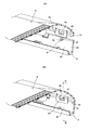
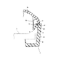
図4は、図3の前キャビネットおよび後キャビネットの構造の一例を示す図である。また、図5や図6は、図3の前キャビネットと後キャビネットとの組み立てを説明する図であり、図5(A)は組み立て前を、図5(B)は組み立て後を示している。図6は、図5(B)のVI-VI線の矢視断面図である。前キャビネット2と後キャビネット8とは、位置決め機構と固定機構を兼ねる構造を有している。
詳しくは、例えば、図3の手前側(図2の左側)に位置した前キャビネット2の右面2dと対応する後キャビネット8の手前側とを例に挙げて説明すると、図4に示すように、後キャビネット8の周縁にはリブ部51が形成され、リブ部51の先端52は、組み立てた際に前キャビネット2の右面2dの内壁40に配置されるように延びている。また、リブ部51よりも内側には爪部53が形成されており、爪部53のヘッド54も右面2dの内壁40に配置されるように延びている。爪部53の根元は湾曲部分を有し、リブ部51寄りの位置で後キャビネット8の内壁50に一体成形されている。
一方、前キャビネット2には、右面2dの内壁40にリブ受容部41が形成されている。リブ受容部41は、リブ部51を受容する溝42を有し、溝42よりも内側には山型のテーパ面43が形成されている。テーパ面43は、爪部53の着脱方向に沿って傾斜方向の異なるテーパを有している。
なお、前キャビネット2の上面2aや左面2bにもリブ受容部が形成され、また、後キャビネット8の対応位置にもリブ部や爪部が形成されており、互いに固着可能である。
なお、前キャビネット2の上面2aや左面2bにもリブ受容部が形成され、また、後キャビネット8の対応位置にもリブ部や爪部が形成されており、互いに固着可能である。
そして、前キャビネット2と後キャビネット8とを連結する場合、まず、図4や図5(A)の状態からリブ部51の先端52がリブ受容部41の溝42に収まり、前キャビネット2に対する後キャビネット8の位置を決めることができる。
リブ部51がリブ受容部41に収まる際、爪部53は撓み、そのヘッド54はテーパ面43に沿ってリブ部51から離れる方向に移動する。ヘッド54は、テーパ面43の頂部分を乗り越えた後、テーパ面43に沿ってリブ部51に近づく方向に移動して所定の挟持位置に到達する。これにより、図5(B)や図6に示すように、リブ受容部41はリブ部51および爪部53で挟持され、前キャビネット2および後キャビネット8の固定が完了する。
リブ部51がリブ受容部41に収まる際、爪部53は撓み、そのヘッド54はテーパ面43に沿ってリブ部51から離れる方向に移動する。ヘッド54は、テーパ面43の頂部分を乗り越えた後、テーパ面43に沿ってリブ部51に近づく方向に移動して所定の挟持位置に到達する。これにより、図5(B)や図6に示すように、リブ受容部41はリブ部51および爪部53で挟持され、前キャビネット2および後キャビネット8の固定が完了する。
これに対し、前キャビネット2と後キャビネット8とを分解する場合、図5(B)や図6の状態において、後キャビネット8を前キャビネット2から引き離す方向に力を加えると、爪部53は撓み、そのヘッド54は、テーパ面43に沿ってリブ部51から離れる方向に移動する。ヘッド54がテーパ面43の頂部分を乗り越えると、リブ部51および爪部53によるリブ受容部41の挟持状態が解除される。その後、ヘッド54は、テーパ面43に沿ってリブ部51に近づく方向に移動するので、爪部53の撓みは解消される。
このように、リブ受容部41が前キャビネット2の内壁40との間でリブ部51を受容し、このリブ受容部41は後キャビネット8に形成されたリブ部51および爪部53で挟んで支持されている。このため、前キャビネット2に対する後キャビネット8の位置決め機構と、前キャビネット2および後キャビネット8の固定機構を兼ねることができ、また、ネジを用いずに実現できる。よって、前キャビネットと後キャビネットとをネジ止めする場合に比べて部品点数や作業工数を削減できる。さらに、ネジを用いないため、組み合わせた前キャビネット2と後キャビネット8との分解も容易である。
そして、リブ受容部41が前キャビネット2の内壁40に形成されることから、これら前キャビネット2と後キャビネット8との連結は、前キャビネット2および後キャビネット8の内側で行える。この結果、前キャビネット2や後キャビネット8の大きさをパネルモジュール3の大きさに近づけ易くなり、前キャビネット2の内壁40とパネルモジュール3の端面との空間を小さくした、額縁を狭めるデザインを達成することができる。
(実施例2)
図7は、図3の前キャビネットおよび後キャビネットの構造の他の例を示す図である。上記実施例では、前キャビネットがリブ受容部を有し、後キャビネットがリブ部や爪部を有した構造の例に挙げて説明している。しかし、本発明は、必ずしもこの形態に限定されるものではなく、前キャビネットがリブ部や爪部を有し、後キャビネットがリブ受容部を有してもよい。
図7は、図3の前キャビネットおよび後キャビネットの構造の他の例を示す図である。上記実施例では、前キャビネットがリブ受容部を有し、後キャビネットがリブ部や爪部を有した構造の例に挙げて説明している。しかし、本発明は、必ずしもこの形態に限定されるものではなく、前キャビネットがリブ部や爪部を有し、後キャビネットがリブ受容部を有してもよい。
詳しくは、図7に示すように、前キャビネット2の周縁にはリブ部61が形成され、リブ部61の先端62は、組み立てた際に後キャビネット8の内壁50に配置されるように延びている。また、リブ部61よりも内側には爪部63が形成されており、爪部63のヘッド64も内壁50に配置されるように延びている。爪部63の根元は湾曲部分を有し、リブ部61寄りの位置で前キャビネット2の右面2dの内壁40に一体成形されている。
一方、後キャビネット8には、内壁50にリブ受容部71が形成されている。リブ受容部71は、リブ部61を受容する溝72を有し、溝72よりも内側には山型のテーパ面73が形成されている。テーパ面73は、爪部63の着脱方向に沿って傾斜方向の異なるテーパを有している。
そして、この場合にも、リブ受容部71をリブ部61および爪部63で挟持しており、上記と同様に、前キャビネットに対する後キャビネットの位置決め、および前キャビネットと後キャビネットとの固定を、ネジを用いずに実現できる。
そして、この場合にも、リブ受容部71をリブ部61および爪部63で挟持しており、上記と同様に、前キャビネットに対する後キャビネットの位置決め、および前キャビネットと後キャビネットとの固定を、ネジを用いずに実現できる。
また、液晶テレビの液晶パネルモジュールについて記述したが、本発明は、それに限られることなく、他の表示装置についても適用できる。表示部分がモジュール構造であればよく、有機EL、プラズマ等であってもよい。
以上、実施例について説明したが、本発明は、所定の被収容物の周囲に設けられた前キャビネットと、前記所定の被収容物の背面を覆う後キャビネットとを備え、前記後キャビネットに形成され、前記前キャビネットの内壁に配置されるように延びたリブ部および前記後キャビネットの内壁にて前記リブ部よりも内側に形成された爪部と、前記前キャビネットの内壁に形成され前記リブ部を受容するリブ受容部とを有し、該リブ受容部を前記リブ部および前記爪部で挟持してもよい。リブ受容部が前キャビネットの内壁との間でリブ部を受容し、このリブ受容部は後キャビネットに形成されたリブ部および爪部で挟んで支持されている。このため、前キャビネットに対する後キャビネットの位置決め機構と、前キャビネットおよび後キャビネットの固定機構を兼ねることができ、また、ネジを用いずに実現できる。よって、前キャビネットと後キャビネットとをネジ止めする場合に比べて部品点数や作業工数を削減できる。さらに、ネジを用いないため、組み合わせた前キャビネットと後キャビネットとの分解も容易である。そして、リブ受容部が前キャビネットの内壁に形成されることから、これらの連結は、前キャビネットおよび後キャビネットの内側で行える。この結果、前キャビネットや後キャビネットの大きさを被収容物の大きさに近づけ易くなり、前キャビネットの内壁と被収容物の端面との空間を小さくした、額縁を狭めるデザインが達成可能になる。
また、所定の被収容物の周囲に設けられた前キャビネットと、前記所定の被収容物の背面を覆う後キャビネットとを備え、前記前キャビネットに形成され、前記後キャビネットの内壁に配置されるように延びたリブ部および前記前キャビネットの内壁にて前記リブ部よりも内側に形成された爪部と、前記後キャビネットの内壁に形成され前記リブ部を受容するリブ受容部とを有し、該リブ受容部を前記リブ部および前記爪部で挟持してもよい。リブ受容部が後キャビネットの内壁との間でリブ部を受容し、このリブ受容部は前キャビネットに形成されたリブ部および爪部で挟んで支持されている。このため、前キャビネットに対する後キャビネットの位置決め機構と、前キャビネットおよび後キャビネットの固定機構を兼ねることができ、また、ネジを用いずに実現できる。よって、前キャビネットと後キャビネットとをネジ止めする場合に比べて部品点数や作業工数を削減できる。さらに、ネジを用いないため、組み合わせた前キャビネットと後キャビネットとの分解も容易である。そして、リブ受容部が後キャビネットの内壁に形成されることから、これらの連結は、前キャビネットおよび後キャビネットの内側で行える。この結果、前キャビネットや後キャビネットの大きさを被収容物の大きさに近づけ易くなり、前キャビネットの内壁と被収容物の端面との空間を小さくした、額縁を狭めるデザインが達成可能になる。
また、前記爪部が、環状に形成されると共に、前記前キャビネットと前記後キャビネットとを連結あるいは分解する場合、前記リブ受容部との接触によって撓んでもよい。この場合、キャビネットの強度不足を回避しつつ、キャビネットを曲げ続ける力も不要になる。
また、前記リブ受容部は、前記爪部の着脱方向に沿って傾斜方向の異なるテーパ面を有し、前記爪部を所定の挟持位置に装着する場合、前記爪部は、前記テーパ面に沿って前記リブ部から離れた後に前記リブ部に近づくことで前記リブ受容部を挟持し、前記爪部を前記リブ部との挟持位置から取り外す場合、前記爪部は、前記テーパ面に沿って前記リブ部から離れた後に前記リブ部に近づくことで前記リブ受容部から取り外されてもよい。この場合、爪部は、リブ部から離れた後にリブ部に近づくように移動するので、所定の挟持位置への装着や所定の挟持位置からの分解を容易に実施することができる。
また、前記所定の被収容物が表示モジュールであってもよく、この場合には、表示装置の額縁を容易に狭めることができる。
また、前記リブ受容部は、前記爪部の着脱方向に沿って傾斜方向の異なるテーパ面を有し、前記爪部を所定の挟持位置に装着する場合、前記爪部は、前記テーパ面に沿って前記リブ部から離れた後に前記リブ部に近づくことで前記リブ受容部を挟持し、前記爪部を前記リブ部との挟持位置から取り外す場合、前記爪部は、前記テーパ面に沿って前記リブ部から離れた後に前記リブ部に近づくことで前記リブ受容部から取り外されてもよい。この場合、爪部は、リブ部から離れた後にリブ部に近づくように移動するので、所定の挟持位置への装着や所定の挟持位置からの分解を容易に実施することができる。
また、前記所定の被収容物が表示モジュールであってもよく、この場合には、表示装置の額縁を容易に狭めることができる。
1…液晶表示装置、2…前キャビネット、2a,3a…上面、2b,3b…左面、2c,3c…下面、2d,3d…右面、2e…突部、3…パネルモジュール、4…液晶パネル、5…背面シャーシ、6…電源基板、7…メイン基板、7a…外部接続端子、7b…放熱板、7c…カバー、8…後キャビネット、9…スタンド、10…コード引出部、11…端子引出部、12…スロット、20,30…補強金具、40,50…内壁、41,71…リブ受容部、42,72…溝、43,73…テーパ面、51,61…リブ部、52,62…先端、53,63…爪部、54,64…ヘッド。
Claims (5)
- 所定の被収容物の周囲に設けられた前キャビネットと、
前記所定の被収容物の背面を覆う後キャビネットとを備え、
前記後キャビネットに形成され、前記前キャビネットの内壁に配置されるように延びたリブ部および前記後キャビネットの内壁にて前記リブ部よりも内側に形成された爪部と、前記前キャビネットの内壁に形成され前記リブ部を受容するリブ受容部とを有し、該リブ受容部を前記リブ部および前記爪部で挟持したことを特徴とする筐体。 - 所定の被収容物の周囲に設けられた前キャビネットと、
前記所定の被収容物の背面を覆う後キャビネットとを備え、
前記前キャビネットに形成され、前記後キャビネットの内壁に配置されるように延びたリブ部および前記前キャビネットの内壁にて前記リブ部よりも内側に形成された爪部と、前記後キャビネットの内壁に形成され前記リブ部を受容するリブ受容部とを有し、該リブ受容部を前記リブ部および前記爪部で挟持したことを特徴とする筐体。 - 請求項1又は2に記載の筐体であって、
前記爪部が、環状に形成されると共に、前記前キャビネットと前記後キャビネットとを連結あるいは分解する場合、前記リブ受容部との接触によって撓むことを特徴とする筐体。 - 請求項1から3のいずれか1項に記載の筐体であって、
前記リブ受容部は、前記爪部の着脱方向に沿って傾斜方向の異なるテーパ面を有し、
前記爪部を所定の挟持位置に装着する場合、前記爪部は、前記テーパ面に沿って前記リブ部から離れた後に前記リブ部に近づくことで前記リブ受容部を挟持し、前記爪部を前記リブ部との挟持位置から取り外す場合、前記爪部は、前記テーパ面に沿って前記リブ部から離れた後に前記リブ部に近づくことで前記リブ受容部から取り外されることを特徴とする筐体。 - 請求項1から4のいずれか1項に記載の筐体を備えた表示装置であって、
前記所定の被収容物が表示モジュールであることを特徴とする表示装置。
Applications Claiming Priority (2)
| Application Number | Priority Date | Filing Date | Title |
|---|---|---|---|
| JP2013-186931 | 2013-09-10 | ||
| JP2013186931A JP5771657B2 (ja) | 2013-09-10 | 2013-09-10 | 筐体および表示装置 |
Publications (1)
| Publication Number | Publication Date |
|---|---|
| WO2015037523A1 true WO2015037523A1 (ja) | 2015-03-19 |
Family
ID=52665629
Family Applications (1)
| Application Number | Title | Priority Date | Filing Date |
|---|---|---|---|
| PCT/JP2014/073439 Ceased WO2015037523A1 (ja) | 2013-09-10 | 2014-09-05 | 筐体および表示装置 |
Country Status (2)
| Country | Link |
|---|---|
| JP (1) | JP5771657B2 (ja) |
| WO (1) | WO2015037523A1 (ja) |
Families Citing this family (2)
| Publication number | Priority date | Publication date | Assignee | Title |
|---|---|---|---|---|
| JP6244782B2 (ja) * | 2013-09-27 | 2017-12-13 | 富士通株式会社 | 電子装置 |
| JP7706923B2 (ja) * | 2021-04-16 | 2025-07-14 | シャープ株式会社 | 表示装置 |
Citations (4)
| Publication number | Priority date | Publication date | Assignee | Title |
|---|---|---|---|---|
| JPS61156352U (ja) * | 1985-03-19 | 1986-09-27 | ||
| JPH11312874A (ja) * | 1998-04-27 | 1999-11-09 | Seiko Epson Corp | 電子機器 |
| JP2005327954A (ja) * | 2004-05-17 | 2005-11-24 | Munekata Co Ltd | 気密ケースの組立方法とその組立方法から得られた気密ケース |
| WO2013005543A1 (ja) * | 2011-07-01 | 2013-01-10 | 三洋電機株式会社 | 電子機器の筐体構造 |
Family Cites Families (1)
| Publication number | Priority date | Publication date | Assignee | Title |
|---|---|---|---|---|
| JP2009200543A (ja) * | 2008-02-19 | 2009-09-03 | Panasonic Corp | キャビネット及び、ディスプレイ装置 |
-
2013
- 2013-09-10 JP JP2013186931A patent/JP5771657B2/ja not_active Expired - Fee Related
-
2014
- 2014-09-05 WO PCT/JP2014/073439 patent/WO2015037523A1/ja not_active Ceased
Patent Citations (4)
| Publication number | Priority date | Publication date | Assignee | Title |
|---|---|---|---|---|
| JPS61156352U (ja) * | 1985-03-19 | 1986-09-27 | ||
| JPH11312874A (ja) * | 1998-04-27 | 1999-11-09 | Seiko Epson Corp | 電子機器 |
| JP2005327954A (ja) * | 2004-05-17 | 2005-11-24 | Munekata Co Ltd | 気密ケースの組立方法とその組立方法から得られた気密ケース |
| WO2013005543A1 (ja) * | 2011-07-01 | 2013-01-10 | 三洋電機株式会社 | 電子機器の筐体構造 |
Also Published As
| Publication number | Publication date |
|---|---|
| JP2015056670A (ja) | 2015-03-23 |
| JP5771657B2 (ja) | 2015-09-02 |
Similar Documents
| Publication | Publication Date | Title |
|---|---|---|
| JP6374323B2 (ja) | 表示装置 | |
| US8057059B2 (en) | Lighting device and display device | |
| JP5519758B2 (ja) | 液晶表示装置 | |
| CN116125703B (zh) | 显示装置、背光模块以及背光模块的组装方法 | |
| TW201335677A (zh) | 背光模組及使用其之顯示裝置 | |
| CN101761834B (zh) | 背光模组及显示装置 | |
| US20120300434A1 (en) | Front Bezel Assembly with Backlight Source, Non-Self-Luminous Display Device with Backlight Source in Front Bezel, and Method for Installing the Backlight Source Thereof | |
| CN105785650B (zh) | 背光源及其组装方法、显示装置 | |
| US9507078B2 (en) | Black light module with mount and displaying apparatus therewith | |
| CN103148463B (zh) | 具可移除定位装置的框体、背光模块、显示模块及其制法 | |
| JP5771657B2 (ja) | 筐体および表示装置 | |
| JP5865887B2 (ja) | 表示装置 | |
| JP6167522B2 (ja) | 表示装置 | |
| JP2012252784A (ja) | 面状光源装置および表示装置 | |
| KR102596527B1 (ko) | 디스플레이 패널용 케이스 및 이를 포함하는 디스플레이 장치 | |
| JP2009162919A (ja) | 表示装置 | |
| JP2015055639A (ja) | 表示装置 | |
| CN109923602B (zh) | 框架组件及显示设备 | |
| CN201093367Y (zh) | 背光组件 | |
| CN204945572U (zh) | 一种具有抽拉式led灯条的背光模组 | |
| JP5069430B2 (ja) | 表示装置 | |
| CN111246141B (zh) | 一种电视机拾音盒体 | |
| WO2015194648A1 (ja) | シャーシ、バックライトシャーシ、表示装置、テレビジョン受像機、及び、電子機器の製造方法 | |
| CN111343399B (zh) | 一种具有远程拾音功能的电视机 | |
| JP2009295493A (ja) | 光源装置及び表示装置 |
Legal Events
| Date | Code | Title | Description |
|---|---|---|---|
| 121 | Ep: the epo has been informed by wipo that ep was designated in this application |
Ref document number: 14844761 Country of ref document: EP Kind code of ref document: A1 |
|
| NENP | Non-entry into the national phase |
Ref country code: DE |
|
| 122 | Ep: pct application non-entry in european phase |
Ref document number: 14844761 Country of ref document: EP Kind code of ref document: A1 |