WO2015037338A1 - シートベルトリトラクタ及びこれを備えるシートベルト装置 - Google Patents
シートベルトリトラクタ及びこれを備えるシートベルト装置 Download PDFInfo
- Publication number
- WO2015037338A1 WO2015037338A1 PCT/JP2014/069593 JP2014069593W WO2015037338A1 WO 2015037338 A1 WO2015037338 A1 WO 2015037338A1 JP 2014069593 W JP2014069593 W JP 2014069593W WO 2015037338 A1 WO2015037338 A1 WO 2015037338A1
- Authority
- WO
- WIPO (PCT)
- Prior art keywords
- seat belt
- spool
- torsion bar
- belt retractor
- retractor
- Prior art date
- Legal status (The legal status is an assumption and is not a legal conclusion. Google has not performed a legal analysis and makes no representation as to the accuracy of the status listed.)
- Ceased
Links
Images








Classifications
-
- B—PERFORMING OPERATIONS; TRANSPORTING
- B60—VEHICLES IN GENERAL
- B60R—VEHICLES, VEHICLE FITTINGS, OR VEHICLE PARTS, NOT OTHERWISE PROVIDED FOR
- B60R22/00—Safety belts or body harnesses in vehicles
- B60R22/28—Safety belts or body harnesses in vehicles incorporating energy-absorbing devices
-
- B—PERFORMING OPERATIONS; TRANSPORTING
- B60—VEHICLES IN GENERAL
- B60R—VEHICLES, VEHICLE FITTINGS, OR VEHICLE PARTS, NOT OTHERWISE PROVIDED FOR
- B60R22/00—Safety belts or body harnesses in vehicles
- B60R22/34—Belt retractors, e.g. reels
- B60R22/341—Belt retractors, e.g. reels comprising energy-absorbing means
-
- B—PERFORMING OPERATIONS; TRANSPORTING
- B60—VEHICLES IN GENERAL
- B60R—VEHICLES, VEHICLE FITTINGS, OR VEHICLE PARTS, NOT OTHERWISE PROVIDED FOR
- B60R22/00—Safety belts or body harnesses in vehicles
- B60R22/34—Belt retractors, e.g. reels
- B60R22/36—Belt retractors, e.g. reels self-locking in an emergency
- B60R22/38—Belt retractors, e.g. reels self-locking in an emergency responsive only to belt movement
-
- B—PERFORMING OPERATIONS; TRANSPORTING
- B60—VEHICLES IN GENERAL
- B60R—VEHICLES, VEHICLE FITTINGS, OR VEHICLE PARTS, NOT OTHERWISE PROVIDED FOR
- B60R22/00—Safety belts or body harnesses in vehicles
- B60R22/34—Belt retractors, e.g. reels
- B60R22/36—Belt retractors, e.g. reels self-locking in an emergency
- B60R22/405—Belt retractors, e.g. reels self-locking in an emergency responsive to belt movement and vehicle movement
-
- B—PERFORMING OPERATIONS; TRANSPORTING
- B60—VEHICLES IN GENERAL
- B60R—VEHICLES, VEHICLE FITTINGS, OR VEHICLE PARTS, NOT OTHERWISE PROVIDED FOR
- B60R22/00—Safety belts or body harnesses in vehicles
- B60R22/34—Belt retractors, e.g. reels
- B60R22/46—Reels with means to tension the belt in an emergency by forced winding up
-
- B—PERFORMING OPERATIONS; TRANSPORTING
- B60—VEHICLES IN GENERAL
- B60R—VEHICLES, VEHICLE FITTINGS, OR VEHICLE PARTS, NOT OTHERWISE PROVIDED FOR
- B60R22/00—Safety belts or body harnesses in vehicles
- B60R22/34—Belt retractors, e.g. reels
- B60R22/46—Reels with means to tension the belt in an emergency by forced winding up
- B60R22/4628—Reels with means to tension the belt in an emergency by forced winding up characterised by fluid actuators, e.g. pyrotechnic gas generators
- B60R22/4633—Linear actuators, e.g. comprising a piston moving along reel axis and rotating along its own axis
-
- B—PERFORMING OPERATIONS; TRANSPORTING
- B60—VEHICLES IN GENERAL
- B60R—VEHICLES, VEHICLE FITTINGS, OR VEHICLE PARTS, NOT OTHERWISE PROVIDED FOR
- B60R22/00—Safety belts or body harnesses in vehicles
- B60R22/34—Belt retractors, e.g. reels
- B60R22/46—Reels with means to tension the belt in an emergency by forced winding up
- B60R22/4676—Reels with means to tension the belt in an emergency by forced winding up comprising energy-absorbing means operating between belt reel and retractor frame
-
- B—PERFORMING OPERATIONS; TRANSPORTING
- B60—VEHICLES IN GENERAL
- B60R—VEHICLES, VEHICLE FITTINGS, OR VEHICLE PARTS, NOT OTHERWISE PROVIDED FOR
- B60R22/00—Safety belts or body harnesses in vehicles
- B60R22/28—Safety belts or body harnesses in vehicles incorporating energy-absorbing devices
- B60R2022/286—Safety belts or body harnesses in vehicles incorporating energy-absorbing devices using deformation of material
- B60R2022/287—Safety belts or body harnesses in vehicles incorporating energy-absorbing devices using deformation of material of torsion rods or tubes
Definitions
- the present invention relates to a technical field of a seat belt retractor that winds up a seat belt so as to be able to be traded, and in particular, a seat belt in an emergency such as when a large vehicle deceleration acts on a vehicle such as a collision in a state of wearing the seat belt.
- An energy absorbing mechanism (hereinafter also referred to as an EA mechanism) that absorbs and relaxes the occupant's energy by limiting the load applied to the seat belt by the action of an energy absorbing member such as torsional deformation of the torsion bar.
- the present invention belongs to a technical field of a seat belt retractor and a seat belt apparatus including the seat belt retractor.
- a seat belt device installed in a vehicle such as an automobile prevents the occupant from jumping out of the seat by restraining the occupant with the seat belt in the above-described emergency.
- Such a seat belt apparatus includes a seat belt retractor that winds up the seat belt.
- the seat belt is wound around the spool when not worn, but is pulled out and worn by the occupant when worn. Then, the seat belt retractor is actuated in the event of an emergency as described above to prevent rotation of the spool in the belt withdrawing direction, thereby preventing the seat belt from being withdrawn. Thereby, the seat belt restrains the occupant in an emergency.
- a torsion bar is provided to absorb and relax energy by limiting a load applied to the seat belt in an emergency with the seat belt mounted.
- the limit load after the collision is only set to one limit load.
- the energy applied to the occupant varies depending on the weight of the occupant. In this way, it is more effective and more appropriate to restrain the occupant by setting the limit load according to the situation in the event of a vehicle emergency as well as responding to various large energy with a single limit load. be able to.
- the seat belt retractor disclosed in Patent Document 1 is provided with two EA mechanisms having different EA characteristics, and one or two of these EA mechanisms are operated depending on an emergency situation.
- the limit load applied to the seat belt can be set in two stages according to the emergency situation.
- the seat belt retractor described in Patent Document 1 has a structure that requires a lot of space.
- the second torsion bar described in Patent Document 1 is provided outside the outer periphery of the shaft, leading to an increase in the size of the seat belt retractor.
- the present invention has been made in view of such circumstances, and the object thereof is to make the limit load applied to the seat belt in accordance with an emergency situation and to further reduce the size. It is an object of the present invention to provide a seat belt retractor that can be used and a seat belt device including the same.
- a seat belt retractor includes a frame, a seat belt, a spool that is rotatably supported by the frame and winds up the seat belt, and a spool of the spool that is not operated.
- a lock mechanism that allows rotation and prevents rotation of the spool in the seat belt pull-out direction during operation, and an energy absorption mechanism that absorbs and relaxes occupant energy by limiting a load applied to the seat belt.
- a first torsion bar that is concentrically built in the spool, has one end held by the spool, the other end can be locked by the lock mechanism, and a rotational force is applied by a torsional force; , Eccentrically incorporated in the spool, one end can be locked by the lock mechanism, and a rotational force is applied by a torsional force.
- the energy absorbing mechanism can be locked by the locking mechanism, and meshes with the first gear that holds the other end of the first torsion bar, and the first gear. And a second gear for holding one end of the second torsion bar.
- the energy absorbing mechanism includes: a pressing member that moves the moving member to a first position and a second position; a driving mechanism that drives the pressing member; And a housing for movably supporting the member, and a housing in which the drive mechanism is installed.
- the housing is separated from the pressing member before the driving mechanism is operated, and the cam portion with which the pressing member abuts when the driving mechanism is operated. It is characterized by having.
- the seat belt retractor it is determined whether or not the information acquired by the passenger information acquisition unit that acquires the passenger information and the information acquired by the passenger information acquisition unit satisfy a predetermined condition. And a controller that moves the moving member to a first position that holds the other end of the second torsion bar and a second position that is separated from the other end of the second torsion bar. It is characterized by that.
- the seat belt retractor includes a pretensioner mechanism that rotates the spool in the seat belt winding direction in an emergency, and the control unit operates the pretensioner mechanism in an emergency and then It is characterized by determining whether the information acquired by the information acquisition unit satisfies a predetermined condition.
- a seat belt retractor includes a seat belt that restrains an occupant, a seat belt retractor that retracts the seat belt so that the seat belt can be pulled out, and that operates in an emergency to prevent the seat belt from being pulled out;
- a seatbelt device comprising at least a tongue slidably supported by the seatbelt pulled out from a seatbelt retractor, and a buckle provided on a vehicle body or a vehicle seat and detachably locked to the tongue. Any one of the aforementioned seat belt retractors according to the present invention is used as the seat belt retractor.
- a lock mechanism that prevents rotation of the spool in the seat belt pull-out direction during operation, and an energy absorption mechanism that absorbs and relaxes occupant energy by limiting a load applied to the seat belt.
- the mechanism is concentrically built in the spool, one end is held by the spool, the other end can be locked by the locking mechanism, and a first torsion bar to which a rotational force is applied by a torsional force; It is eccentrically incorporated in the spool, one end can be locked by the lock mechanism, and a rotational force is applied by a torsional force.
- 2 torsion bar rotating together with the spool and moving to a first position holding the other end of the second torsion bar and a second position spaced from the other end of the second torsion bar Therefore, it is possible to form a compact structure, to perform an accurate operation, and to apply the seat belt tension smoothly.
- the energy absorbing mechanism can be locked by the locking mechanism, and meshes with the first gear that holds the other end of the first torsion bar, and the first gear. And the second gear that holds one end of the second torsion bar, the first torsion bar and the second torsion bar can be accurately connected.
- the energy absorbing mechanism includes: a pressing member that moves the moving member to a first position and a second position; a driving mechanism that drives the pressing member; And a housing in which the driving mechanism is installed.
- the pressing mechanism is driven by the driving mechanism installed in the strong housing, and the moving member is moved to move each member. Interact with each other to enable more accurate operation.
- the housing is separated from the pressing member before the driving mechanism is operated, and the cam portion with which the pressing member abuts when the driving mechanism is operated. Therefore, the movement of the moving member is performed by the contact between the pressing member and the cam portion, thereby enabling more accurate operation.
- the seat belt retractor it is determined whether or not the information acquired by the passenger information acquisition unit that acquires the passenger information and the information acquired by the passenger information acquisition unit satisfy a predetermined condition. And a controller that moves the moving member to a first position that holds the other end of the second torsion bar and a second position that is separated from the other end of the second torsion bar. Therefore, control according to the occupant is possible, and more accurate operation is possible.
- the seat belt retractor includes a pretensioner mechanism that rotates the spool in the seat belt winding direction in an emergency, and the control unit operates the pretensioner mechanism in an emergency and then Since it is determined whether or not the information acquired by the information acquisition unit satisfies a predetermined condition, it is possible to quickly wind up the seat belt in an emergency.
- the seatbelt retractor can be made compact, so that the degree of freedom of arrangement of each part of the seatbelt device can be further increased.
- FIG. 1 It is a perspective view showing typically a seat belt device provided with an example of an embodiment of a seat belt retractor concerning the present invention. It is a disassembled perspective view of the seatbelt retractor of this embodiment. It is a perspective view which shows a part of EA mechanism of the seatbelt retractor of this embodiment. It is a perspective view which shows a part of EA mechanism of the seatbelt retractor of this embodiment. It is a perspective view which shows the housing of the EA mechanism of the seatbelt retractor of this embodiment. It is a side view which shows EA mechanism of the seatbelt retractor of this embodiment. It is a front view which shows the EA mechanism of the seatbelt retractor of this embodiment. FIG.
- FIG. 7 is a cross-sectional view taken along line AA in FIG. 6.
- FIG. 8 is a cross-sectional view taken along line BB in FIG.
- FIG. 8 is a cross-sectional view taken along the line CC of FIG. It is an enlarged view of D part of FIG.
- It is a perspective view which shows a part of EA mechanism 20 after the micro gas generator action
- FIG. 8 is a cross-sectional view taken along the line CC of FIG.
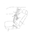
- FIG. 1 is a diagram schematically showing a seat belt apparatus including an example of an embodiment of a seat belt retractor according to the present invention.
- the seat belt device 1 of this example is the same as a conventionally known three-point seat belt device.
- 1 is a seat belt device
- 2 is a vehicle seat
- 3 is a seat belt retractor disposed in the vicinity of the vehicle seat
- 4 is a seat belt retractor 3 that is retracted and retracted to the seat belt retractor 3 Is fixed to the floor of the vehicle body or the vehicle seat 2
- 5 is a guide anchor for guiding the seat belt 4 pulled out from the seat belt retractor 3 toward the occupant's shoulder, and 6 is guided from this guide anchor 5.
- a tongue 7 slidably supported by the seat belt 4 is a buckle fixed to the floor of the vehicle body or the vehicle seat and to which the tongue 6 is detachably inserted.
- the seatbelt 4 mounting operation and mounting release operation in the seatbelt apparatus 1 are the same as those of a conventionally known seatbelt apparatus.
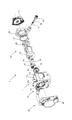
- FIG. 2 is an exploded perspective view of the seat belt retractor of this example.
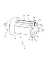
- the seat belt retractor 3 in this example includes a frame 11, a spool 12, a spring portion 13, an EA mechanism 20, a deceleration sensing means 40, a pretensioner mechanism 50, and a lock mechanism 60. And comprising.
- the frame 11 includes a back plate 11a and left and right side walls 11b and 11c projecting in a direction orthogonal from both ends of the back plate 11a, and has a U-shaped cross section. Circular openings are formed in the left and right side walls 11b and 11c of the frame 11, respectively.
- the spool 12 includes an intermediate portion 12a, a first flange 12b installed at one end of the intermediate portion 12a, a second flange 12c installed at the other end of the intermediate portion 12a, and a shaft portion protruding from the second flange 12c. 12d.
- the spool 12 is rotatably disposed through an opening formed in the side wall of the frame 11.
- One end of the seat belt 4 shown in FIG. 1 is locked to the outer periphery of the intermediate portion 12a, and the seat belt 4 is wound thereon. Further, the groove portion 12a 1 is formed in the axial direction in the intermediate portion 12a.
- a first hole 12b 1 is formed in the center of the first flange 12b, and a second hole 12b 2 is formed at a position eccentric with respect to the axial center of the spool 12.
- the first hole portion 12b 1 is formed with a first step portion 12b 11 having a small diameter in the axial direction
- the second hole portion 12b 2 is a second step portion 12b 21 having a small diameter in the axial direction. Is formed.
- the first hole 12b 1 and the second hole 12b 2 are partially connected.
- the second flange 12c, the third hole portion 12c 1 is formed at a position facing the second hole portion 12b 2 of the first flange 12b.
- a plurality of cylindrical guide portion 12c 2 is formed around the shaft portion 12d of the second flange 12c.
- the guide portion 12c 2 has a function of guiding when a later-described release ring 25 moves in the axial direction, and is not limited to a columnar shape but may have another shape.
- the spring portion 13 has one end connected to the shaft portion 12d of the spool 12, the other end attached to the case, and a spring (not shown) that urges the spool 12 in the belt winding direction.
- FIG. 3 and 4 are perspective views showing a part of the EA mechanism 20 of the seat belt retractor of the present embodiment.
- FIG. 5 is a perspective view showing a housing of the EA mechanism 20 of the seat belt retractor of the present embodiment.
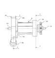
- FIG. 6 is a side view showing the EA mechanism 20 of the seat belt retractor of the present embodiment.
- FIG. 7 is a front view showing the EA mechanism 20 of the seat belt retractor of the present embodiment.
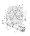
- FIG. 8 is a cross-sectional view taken along line AA in FIG. 9 is a cross-sectional view taken along line BB in FIG. 10 is a cross-sectional view taken along the line CC of FIG.
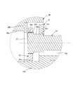
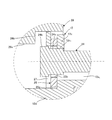
- FIG. 11 is an enlarged view of a portion D in FIG.
- the EA mechanism 20 includes a first torsion bar 21, a first gear 22, a second gear 23, a second torsion bar 24, a release ring 25, a housing 26, a lever ring 27, and a micro gas generator 28. , An O-ring 29 and a piston 30.
- the release ring 25 constitutes a moving member
- the lever ring 27 constitutes a pressing member
- the micro gas generator 28 constitutes a driving mechanism.
- the first torsion bar 21 is stored concentrically inside the intermediate portion 12a of the spool 12.
- One end 21 a of the first torsion bar 21 is held on the second flange 12 c side of the spool 12 so as to rotate integrally with the spool 12.
- the other end 21 b of the first torsion bar 21 is held in the first recess 22 a of the first gear 22 so as to rotate integrally with the first gear 22.
- the first gear 22 has a first recess 22a that accommodates the other end of the first torsion bar 21 inside, and first gear teeth 22b that are formed on the outer periphery on the side where the first recess 22a is formed.
- the first gear 22 has a shaft portion 22c on the opposite side of the first recess 22a.
- the first gear 22 is attached to the first torsion bar 21 so as to cover one end of the intermediate portion 12 a inside the first hole portion 12 b 1 of the first flange 12 b of the spool 12.
- the spool 12 and the first gear 22 are assembled so as to be relatively rotatable.
- the second gear 23 has a second gear tooth 23a formed on one outer periphery in the axial direction and a second recess 23b formed on the other inner side.
- the second gear 23 is housed inside the second hole 12 b 2 of the first flange 12 b of the spool 12.
- the second gear teeth 23a mesh with the first gear teeth 22b of the first gear 22 at a portion where the first hole 12b 1 and the second hole 12b 2 are connected.
- the second recess 23 b holds one end of the second torsion bar 24.
- the second torsion bar 24 is housed eccentrically with respect to the center of the spool 12 in a groove 12 a 1 formed in the intermediate portion 12 a of the spool 12.
- One end 24a of the second torsion bar 24 is held in the second concave portion 23b of the second gear 23, the other end portion 24b is the third hole portion 12c 1 of the second flange 12c penetrates, usually release ring 25.
- a small diameter portion 24c having a smaller diameter than the other end portion 24b is formed on the inner side in the axial direction of the other end portion 24b of the second torsion bar 24.
- the release ring 25 is formed with a central hole 25a through which the shaft portion 12d protruding from the second flange 12c of the spool 12 passes. Also, the release ring 25, retention hole 25b for retaining the second torsion bar 24 is formed at a position opposing the third hole portion 12c 1 of the second flange 12c, formed in the second flange 12c around the central hole 25a and the guide portion 12c 2 are a plurality of small holes 25c are formed to penetrate.
- the release ring 25 is movable in the axial direction of the spool 12.
- the holding hole 25b of the release ring 25 and the other end 24b of the second torsion bar 24 are engaged, the second torsion bar 24 is held so as to rotate integrally with the release ring 25. Therefore, the second gear 23 that rotates integrally with the second torsion bar 24 cannot rotate.
- the release ring 25 moves in the axial direction, the holding hole 25b of the release ring 25 moves to a position corresponding to the small diameter portion 24c of the second torsion bar 24, and the second torsion bar 24 and the release ring 25 are separated from each other.
- the second torsion bar 24 idles with respect to the release ring 25. Therefore, the second torsion bar 24 and the second gear 23 can rotate together.
- a through hole 26 a is formed in the housing 26.
- An annular step 26b is formed on the inner peripheral side of the through hole 26a, and a slope 26c 1 formed in the circumferential direction and a top surface 26c 2 formed at the highest position of the slope 26c 1 are formed on the annular step 26b.
- a plurality of cam portions 26c are formed.
- An annular protrusion 26d is formed on the outer periphery of the through hole 26a.
- a gap is formed in a part of the annular projecting portion 26d, and a lever moving region 26e in which the lever portion 27b of the lever ring 27 is movably disposed is formed on the outer peripheral side of the gap.
- the housing 26 is formed with a connecting hole 26g that connects the outer surface 26f of the housing 26 to the lever moving region 26e, and a gas generator mounting portion 26h is attached to the connecting hole 26g.
- the lever ring 27 has a ring portion 27 a, a lever portion 27 b, and a notch portion 27 c and is installed adjacent to the release ring 25.
- the ring portion 27 a is an annular portion and is concentrically installed on the housing 26 so as to overlap the release ring 25.
- the lever portion 27 b protrudes in the radial direction from the outer periphery of the ring portion 27 a and is disposed in the lever moving region 26 e of the housing 26.
- a receiving portion 27b 1 that is pressed by the piston 30 of the micro gas generator 28 is formed at the end of the lever portion 27b.
- the notch 26 c is formed on the outer periphery of the ring portion 27 a so as to correspond to the cam portion 26 c of the housing 26.
- the micro gas generator 28 has a built-in piston 30 and is attached to the gas generator attachment portion 26h via an O-ring 29.
- the seat belt retractor 3 includes a deceleration sensing means 40, a pretensioner mechanism 50, and a lock mechanism 60. These may have a conventional configuration.
- the lock mechanism 60 has a lock pawl 61 and a locking base 62.
- the lock pawl 61 is rotatably installed on the side wall of the frame 11.
- the locking base 62 is integrally coupled to the shaft portion 22 c of the first gear 22. That is, the locking base 62 and the first gear 22 rotate integrally. Further, the lock pawl 61 meshes with the locking base 62 by rotating, and locks the rotation of the locking base 62 and the first gear 22.
- the deceleration sensing means 40 senses a large vehicle deceleration that occurs in an emergency, and the pretensioner mechanism 50 and the lock mechanism 60 start operating.
- the EA mechanism 20 is operated, and the EA mechanism 20 of the present embodiment has two types of operation methods of a first operation state and a second operation state.
- the EA mechanism 20 In the first operating state, the EA mechanism 20 is in the state shown in FIGS. 3 to 11 because the micro gas generator 28 does not operate. After the pretensioner mechanism 50 is actuated and the spool 12 rotates in the winding direction, the spool 12 rotates in the belt pulling direction so that the seat belt 4 is pulled out by the inertia of the occupant. However, the locking base 62 and the first gear 22 attached to the first flange 12 b of the spool 12 are locked by the lock pawl 61.
- the first torsion bar 21 in which the one end 21a is held by the spool 12 and the other end 21b is held by the first gear 22 is twisted. That is, the first torsion bar 21 allows the predetermined seat belt 4 to be pulled out and absorbs energy while the force limiter load is applied.
- the second gear 23 moves together with the spool 12, it rotates while meshing with the first gear 22. Therefore, the second torsion bar 24 in which the one end 24a is held by the second gear 23 and the other end 24b is held by the release ring 25 is twisted. That is, the second torsion bar 24 allows the predetermined seat belt 4 to be pulled out and absorbs energy while the force limiter load is applied.
- the first torsion bar 21 and the second torsion bar 24 act together to absorb energy.
- FIG. 12 is a perspective view showing a part of the EA mechanism 20 after the micro gas generator of the seat belt retractor of the present embodiment is activated.
- FIG. 13 is a perspective view showing the housing after the micro gas generator of the EA mechanism 20 of the seat belt retractor of the present embodiment is operated.
- 14 is a cross-sectional view taken along line BB of FIG. 7 after the micro gas generator is activated.
- 15 is a cross-sectional view taken along line CC of FIG. 7 after the micro gas generator is activated.
- FIG. 16 is an enlarged view of a portion D in FIG. 8 after the micro gas generator is activated.
- the EA mechanism 20 is in the state shown in FIGS. 12 to 16 because the micro gas generator 28 operates.
- the pretensioner mechanism 50 is actuated and the spool 12 rotates in the winding direction
- the spool 12 rotates in the belt pulling-out direction so that the seat belt 4 is pulled out by the inertia of the occupant.
- the locking base 62 and the first gear 22 attached to the first flange 12 b of the spool 12 are locked by the lock pawl 61.
- the first torsion bar 21 in which the one end 21a is held by the spool 12 and the other end 21b is held by the first gear 22 is twisted. That is, the first torsion bar 21 allows the predetermined seat belt 4 to be pulled out and absorbs energy while the force limiter load is applied.
- the micro gas generator 28 is operated and the piston 30 is fired.
- the piston 30 presses the receiving portion 27b 1 of the lever portion 27b of the lever ring 27.
- the lever ring 27 whose lever portion 27b is pressed starts to rotate.
- it moves along the inclined surface 26c 1 of the cam portion 26c formed on the annular step portion 26b of the housing 26 of the ring portion 27a of the lever ring 27 has been positioned in the notch 27c, rides on the top surface 26c 2.
- the moved lever ring 27 presses the release ring 25, and the release ring 25 moves in the axial direction.
- the holding hole 25b of the release ring 25 moves to a position corresponding to the small diameter portion 24c of the second torsion bar 24, and the other end 24b of the second torsion bar 24 is separated from the release ring 25 and Idle. Therefore, the second torsion bar 24 and the second gear 23 can rotate together, and the second torsion bar 24 is not twisted. That is, the force limiter load does not act on the second torsion bar 24.
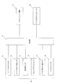
- FIG. 17 is a system diagram of the EA mechanism of the seat belt retractor of the present embodiment.
- the control unit 77 includes a seat weight sensor 71, a seat slide position detection sensor 72, an acceleration sensor 73, a front satellite sensor 74, a belt extension amount sensor 75, and Based on the output signals from the occupant information acquisition unit 70 such as the buckle switch 76, the operations of the pretensioner mechanism 50 and the micro gas generator 28 are controlled according to the emergency situation.
- the control unit 77 is configured by a CPU or the like.
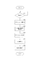
- FIG. 18 is a view showing a control flowchart of the seat belt retractor of the present embodiment.
- FIG. 19 is a diagram showing a control flowchart of the EA mechanism of the seat belt retractor of the present embodiment.
- step 1 it is determined whether or not it is an emergency (ST1). Whether or not it is an emergency is determined by whether or not the acceleration sensor 73 has detected a sudden deceleration exceeding a predetermined value due to a collision or the like. If it is determined in step 1 that it is not an emergency, the process returns to step 1.
- step 2 If it is determined in step 1 that there is an emergency, the pretensioner mechanism 50 is activated in step 2 (ST2).
- step 3 EA mechanism operation state selection control is executed (ST3).
- step 31 occupant information is acquired (ST31).
- the occupant information is acquired from each sensor shown in FIG.
- step 32 it is determined whether or not the occupant information acquired in step 31 satisfies a predetermined condition (ST32). For example, it is determined whether the load acquired by the seat weight sensor 71 is greater than or equal to a predetermined value or smaller than a predetermined value.
- step 32 the first operating state in which the micro gas generator 28 is not operated is selected in step 33 (ST33). If the condition is not satisfied in step 32, a second operating state for operating the micro gas generator 28 is selected in step 34 (ST34). After selecting the operating state of the EA mechanism, the EA mechanism operating state selection control is terminated.
- the first operating state is selected, and the load acquired by the seat weight sensor 71 is smaller than a predetermined value
- the second operating state is selected.
- step 4 the operation of the pretensioner mechanism 50 ends (ST4).
- step 5 the EA mechanism 20 is operated in the operation state selected in the EA mechanism operation state selection control in step 3 (ST5).
- step 6 the operation of the EA mechanism 20 is terminated (ST6).
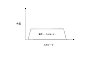
- FIG. 20 is a diagram showing a load with respect to a stroke in the first operating state of the EA mechanism of the seat belt retractor of the present embodiment.
- FIG. 21 is a diagram illustrating a load with respect to a stroke in the second operating state of the EA mechanism of the seat belt retractor of the present embodiment.
- the seat belt retractor 3 of this example information that can be known in advance (for example, information on the weight of the occupant, information on the seat slide position, etc.), collision prediction information that predicts a collision, and severity of the collision (For example, collision speed information, collision acceleration / deceleration information, collision method information, etc.), etc.
- the limit load of the seat belt 4 is changed.
- the limit load of the seat belt in the event of an emergency such as a collision can be set according to the emergency information such as the emergency situation and the size of the occupant. Thereby, an occupant can be restrained more effectively and appropriately in an emergency.
- the seat belt retractor 3 can be formed small and compact in the vertical direction. Thereby, the effective space in a vehicle interior can be enlarged correspondingly.
- the micro gas generator 28 is used as a driving member that presses the lever portion 27b of the lever ring 27.
- the driving member may be, for example, an electromagnetic wave. It is also possible to press the lever portion 27b with a driving force by other means such as pressing the lever portion 27b with an electromagnetic force by a solenoid. In that case, the electromagnetic solenoid may be driven and controlled by the control unit 77 in the same manner as in the above example.
- the frame 11, the seat belt 4, the spool 12 that is rotatably supported by the frame 11 and winds up the seat belt 4, and the non-operating state.
- a lock mechanism 60 that allows rotation of the spool 12 and prevents rotation of the spool 12 in the pull-out direction of the seat belt 4 during operation; and an energy absorption mechanism 20 that absorbs and relaxes occupant energy by limiting the load applied to the seat belt 4.
- the energy absorption mechanism 20 is concentrically built in the spool 12, the one end 21 a is held by the spool 12, and the other end 21 b can be locked by the lock mechanism 60, and the rotational force is generated by a torsional force.
- the first torsion bar 21 to be provided and the first torsion bar 21 are eccentrically incorporated in the spool 12, and the one end 24 a is locked by the lock mechanism 60.
- a second torsion bar 24 to which a rotational force is applied by a torsional force a first position that rotates integrally with the spool 12 and holds the other end 24b of the second torsion bar 24, and a second position.
- the release ring 25 moves to a second position separated from the other end 24b of the torsion bar 24, so that it is formed into a compact structure, enables accurate operation, and smoothly increases the seat belt tension. It becomes possible to grant.
- the energy absorbing mechanism 20 can be locked by the lock mechanism 60, and the first gear 22 that holds the other end of the first torsion bar 21, Since it has the 2nd gear 23 which meshes
- the energy absorbing mechanism 20 includes a lever ring 27 that moves the release ring 25 to the first position and the second position, and a micro gas generator 28 that drives the lever ring 27.
- the lever ring 27 is movably supported and has a housing 26 in which the micro gas generator 28 is installed. Therefore, the lever ring 27 is driven and released by the micro gas generator 28 installed in the strong housing 26. By moving the ring 25, the members interact with each other, and a more accurate operation is possible.
- the housing 26 is separated from the lever ring 27 before the micro gas generator 28 operates, and the cam that the lever ring 27 contacts when the micro gas generator 28 operates. Since the portion 26c is provided, the release ring 25 is moved by the contact between the lever ring 27 and the cam portion 26c, so that more accurate operation can be performed.
- the occupant information acquisition unit 70 that acquires the occupant information and whether the information acquired by the occupant information acquisition unit 70 satisfies a predetermined condition are determined. Accordingly, the control unit 77 moves the release ring 25 to a first position that holds the other end 24b of the second torsion bar 24 and a second position that is separated from the other end 24b of the second torsion bar 24. Therefore, the control according to the occupant is possible, and more accurate operation is possible.
- the seat belt retractor includes a pretensioner mechanism 50 that rotates the spool 12 in the winding direction of the seatbelt 4 in an emergency, and the control unit activates the pretensioner mechanism in an emergency, and then occupant information Since it is determined whether or not the information acquired by the acquisition unit 70 satisfies a predetermined condition, the seat belt 4 can be wound quickly in an emergency.
- the seatbelt retractor 3 can be made compact, so that the degree of freedom of arrangement of each part of the seatbelt device can be further increased.
- the seat belt retractor of the present invention is used in a seat belt device attached to a vehicle such as an automobile, and the seat belt is withdrawn while absorbing and easing the occupant's energy by limiting the load applied to the seat belt in an emergency such as a collision. It can be suitably used for a seat belt retractor that prevents the above.
Landscapes
- Engineering & Computer Science (AREA)
- Mechanical Engineering (AREA)
- Automotive Seat Belt Assembly (AREA)
Abstract
【課題】 コンパクトな構造に形成し、的確なロック動作が可能であると共に、円滑にシートベルト張力を付与することが可能なシートベルトリトラクタおよびこれを備えるシートベルト装置を提供する。 【解決手段】 シートベルトリトラクタ3は、フレーム11と、シートベルト4と、フレーム11に回転可能に支持されるとともにシートベルト4を巻き取るスプール12と、非作動時にスプール12の回転を許容し、作動時にスプール12のシートベルト4引出し方向の回転を阻止するロック機構60と、シートベルト4にかかる荷重を制限して乗員のエネルギを吸収緩和するエネルギ吸収機構20と、を備え、エネルギ吸収機構20は、スプール12内に同心に内蔵され、一端部21aがスプール12に保持され、他端部21bがロック機構60でロック可能であって、ねじり力で回転力が付与される第1トーションバー21と、スプール12内に偏心して内蔵され、一端部24aがロック機構60でロック可能であって、ねじり力で回転力が付与される第2トーションバー24と、スプール12と一体に回転すると共に、第2トーションバー24の他端部24bを保持する第1の位置と第2トーションバー24の他端部24bから離間する第2の位置とに移動する移動部材25と、を有することを特徴とする。
Description
本発明は、シートベルトを巻取引出し可能に巻き取るシートベルトリトラクタの技術分野に関し、特に、シートベルト装着状態で衝突時等の車両に大きな車両減速度が作用した場合のような緊急時にシートベルトの引出しを阻止する際、トーションバーのねじれ変形などのエネルギ吸収部材の作用によりこのシートベルトにかかる荷重を制限して乗員のエネルギを吸収緩和するエネルギ吸収機構(以下、EA機構ともいう)を備えているシートベルトリトラクタおよびこれを備えているシートベルト装置の技術分野に属するものである。
従来から自動車等の車両に装備されているシートベルト装置は、前述の緊急時に、シートベルトで乗員を拘束することにより乗員のシートからの飛び出しを阻止する。
このようなシートベルト装置においては、シートベルトを巻き取るシートベルトリトラクタを備えている。このシートベルトリトラクタでは、シートベルトは非装着時にはスプールに巻き取られているが、装着時には引き出されて乗員に装着される。そして、前述のような緊急時にシートベルトリトラクタのロック手段が作動してスプールのベルト引出方向の回転を阻止することにより、シートベルトの引出しが阻止される。これにより、緊急時にシートベルトは乗員を拘束する。
ところで、この従来のシートベルト装置のシートベルトリトラクタにおいては、車両衝突等の緊急時にシートベルトが乗員を拘束するとき、大きな車両減速度が生じるため、乗員が大きな慣性により前方へ移動しようとする。このため、シートベルトには大きな荷重が加えられるとともに、乗員はこのシートベルトから大きなエネルギを加えられるようになる。乗員に対してこのエネルギは特に問題ではないが、できれば制限される方が望ましい。
そこで、シートベルトリトラクタにおいては、従来、トーションバーを設けて、シートベルト装着状態での緊急時に、このシートベルトにかかる荷重を制限してエネルギを吸収緩和するようにしたものが開発されている。
しかしながら、従来のシートベルトリトラクタは、衝突後の制限荷重が1つの制限荷重に設定されるだけである。実際には、乗員に加えられるエネルギは、乗員の体重等によって種々異なる。このように種々異なる大きなエネルギに対して、1つの制限荷重で対応するだけではなく、車両緊急時の状況に応じて制限荷重を設定する方が、乗員をより効果的にかつより適切に拘束することができる。
そこで、シートベルトにかかる制限荷重を種々設定することができるシートベルトリトラクタが提案されている(例えば、特許文献1参照)。
この特許文献1に開示のシートベルトリトラクタは、EA特性の異なる2つのEA機構を設けるとともに、これらのEA機構を緊急時の状況に応じて1つまたは2つ作動するようにしている。このように、2つのEA機構を適宜選択して作動することで、シートベルトにかかる制限荷重を緊急時の状況に応じて2段階に設定することができる。
しかしながら、特許文献1に記載されたシートベルトリトラクタは、多くのスペースが必要となる構造であった。例えば、特許文献1に記載された第2ねじれバーは、シャフトの外周の外側にもうけられており、シートベルトリトラクタの大型化を招いていた。
本発明は、このような事情に鑑みてなされたものであって、その目的は、シートベルトにかかる制限荷重を緊急時の状況に応じて設定することができるようにしつつ、より一層小型に形成できるシートベルトリトラクタおよびこれを備えているシートベルト装置を提供することである。
前述の課題を解決するために、本発明に係るシートベルトリトラクタは、フレームと、シートベルトと、前記フレームに回転可能に支持されるとともに前記シートベルトを巻き取るスプールと、非作動時に前記スプールの回転を許容し、作動時に前記スプールのシートベルト引出し方向の回転を阻止するロック機構と、前記シートベルトにかかる荷重を制限して乗員のエネルギを吸収緩和するエネルギ吸収機構と、を備え、前記エネルギ吸収機構は、前記スプール内に同心に内蔵され、一端部が前記スプールに保持され、他端部が前記ロック機構でロック可能であって、ねじり力で回転力が付与される第1トーションバーと、前記スプール内に偏心して内蔵され、一端が前記ロック機構でロック可能であって、ねじり力で回転力が付与される第2トーションバーと、前記スプールと一体に回転すると共に、前記第2トーションバーの他端部を保持する第1の位置と前記第2トーションバーの他端部から離間する第2の位置とに移動する移動部材と、を有することを特徴とする。
また、本発明に係るシートベルトリトラクタでは、前記エネルギ吸収機構は、 前記ロック機構によってロック可能であって、前記第1トーションバーの他端部を保持する第1ギヤと、前記第1ギヤと噛み合い、前記第2トーションバーの一端部を保持する第2ギヤと、を有することを特徴とする。
また、本発明に係るシートベルトリトラクタでは、前記エネルギ吸収機構は、 前記移動部材を第1の位置と第2の位置とに移動させる押圧部材と、前記押圧部材を駆動する駆動機構と、前記押圧部材を移動可能に支持すると共に、前記駆動機構が設置されるハウジングと、を有することを特徴とする。
また、本発明に係るシートベルトリトラクタでは、前記ハウジングは、前記駆動機構が作動する前に、前記押圧部材と離間しており、前記駆動機構が作動した時に、前記押圧部材が当接するカム部を有することを特徴とする。
また、本発明に係るシートベルトリトラクタでは、乗員情報を取得する乗員情報取得部と、前記乗員情報取得部が取得した情報が予め定めた条件を満足するか否かを判定し、判定した結果に応じて、前記第2トーションバーの他端部を保持する第1の位置と前記第2トーションバーの他端部から離間する第2の位置とに前記移動部材を移動させる制御部と、を備えることを特徴とする。
また、本発明に係るシートベルトリトラクタでは、緊急時に前記スプールを前記シートベルトの巻き取り方向へ回転させるプリテンショナー機構を備え、前記制御部は、緊急時にプリテンショナー機構を作動させた後、前記乗員情報取得部が取得した情報が予め定めた条件を満足するか否かを判定することを特徴とする。
さらに、本発明に係るシートベルトリトラクタ装置は、乗員を拘束するシートベルトと、前記シートベルトを引き出し可能に巻き取るとともに、緊急時に作動して前記シートベルトの引出しを阻止するシートベルトリトラクタと、前記シートベルトリトラクタから引き出された前記シートベルトに摺動可能に支持されたタングと、車体または車両シートに設けられ、前記タングが離脱可能に係止されるバックルと、を少なくとも備えるシートベルト装置において、前記シートベルトリトラクタに、前述の本発明に係るシートベルトリトラクタのいずれか1つが用いられていることを特徴とする。
このように構成された本発明に係るシートベルトリトラクタによれば、フレームと、シートベルトと、前記フレームに回転可能に支持されるとともに前記シートベルトを巻き取るスプールと、非作動時に前記スプールの回転を許容し、作動時に前記スプールのシートベルト引出し方向の回転を阻止するロック機構と、前記シートベルトにかかる荷重を制限して乗員のエネルギを吸収緩和するエネルギ吸収機構と、を備え、前記エネルギ吸収機構は、前記スプール内に同心に内蔵され、一端部が前記スプールに保持され、他端部が前記ロック機構でロック可能であって、ねじり力で回転力が付与される第1トーションバーと、前記スプール内に偏心して内蔵され、一端が前記ロック機構でロック可能であって、ねじり力で回転力が付与される第2トーションバーと、前記スプールと一体に回転すると共に、前記第2トーションバーの他端部を保持する第1の位置と前記第2トーションバーの他端部から離間する第2の位置とに移動する移動部材と、を有するので、コンパクトな構造に形成し、的確な動作が可能となると共に、円滑にシートベルト張力を付与することが可能となる。
また、本発明に係るシートベルトリトラクタでは、前記エネルギ吸収機構は、 前記ロック機構によってロック可能であって、前記第1トーションバーの他端部を保持する第1ギヤと、前記第1ギヤと噛み合い、前記第2トーションバーの一端部を保持する第2ギヤと、を有するので、前記第1トーションバーと前記第2トーションバーを的確に連結することが可能となる。
また、本発明に係るシートベルトリトラクタでは、前記エネルギ吸収機構は、 前記移動部材を第1の位置と第2の位置とに移動させる押圧部材と、前記押圧部材を駆動する駆動機構と、前記押圧部材を移動可能に支持すると共に、前記駆動機構が設置されるハウジングと、を有するので、強固なハウジングに設置された駆動機構によって、押圧部材を駆動し、移動部材を移動させることで、各部材が相互に作用し、さらに的確な動作が可能となる。
また、本発明に係るシートベルトリトラクタでは、前記ハウジングは、前記駆動機構が作動する前に、前記押圧部材と離間しており、前記駆動機構が作動した時に、前記押圧部材が当接するカム部を有するので、移動部材の移動を押圧部材とカム部との当接によって行うことで、さらに的確な動作が可能となる。
また、本発明に係るシートベルトリトラクタでは、乗員情報を取得する乗員情報取得部と、前記乗員情報取得部が取得した情報が予め定めた条件を満足するか否かを判定し、判定した結果に応じて、前記第2トーションバーの他端部を保持する第1の位置と前記第2トーションバーの他端部から離間する第2の位置とに前記移動部材を移動させる制御部と、を備えるので、乗員に応じた制御が可能となり、さらに的確な動作が可能となる。
また、本発明に係るシートベルトリトラクタでは、緊急時に前記スプールを前記シートベルトの巻き取り方向へ回転させるプリテンショナー機構を備え、前記制御部は、緊急時にプリテンショナー機構を作動させた後、前記乗員情報取得部が取得した情報が予め定めた条件を満足するか否かを判定するので、緊急時に迅速にシートベルトを巻き取ることが可能となる。
この例のシートベルトリトラクタを備えるシートベルト装置によれば、シートベルトリトラクタをコンパクトにできることから、シートベルト装置の各部品の配置の自由度をより高くすることが可能となる。
以下、図面を用いて本発明を実施するための形態について説明する。
図1は、本発明にかかるシートベルトリトラクタの実施の形態の一例を備えるシートベルト装置を模式的に示す図である。
図1に示すように、この例のシートベルト装置1は、従来公知の三点式シートベルト装置と同じである。図中、1はシートベルト装置、2は車両シート、3は車両シート2の近傍に配設されたシートベルトリトラクタ、4はシートベルトリトラクタ3に引き出し可能に巻き取られかつ先端のシートベルトアンカー4aが車体の床あるいは車両シート2に固定されるシートベルト、5はシートベルトリトラクタ3から引き出されたシートベルト4を乗員のショルダーの方へガイドするガイドアンカー、6はこのガイドアンカー5からガイドされてきたシートベルト4に摺動自在に支持されたタング、7は車体の床あるいは車両シートに固定されかつタング6が係脱可能に挿入係止されるバックルである。このシートベルト装置1におけるシートベルト4の装着操作および装着解除操作も、従来公知のシートベルト装置と同じである。
図2は、この例のシートベルトリトラクタの分解斜視図である。
図2に示すように、この例におけるシートベルトリトラクタ3は、フレーム11と、スプール12と、スプリング部13と、EA機構20と、減速度感知手段40と、プリテンショナー機構50と、ロック機構60と、を備える。
フレーム11は、背板11aと、この背板11aの両側端から直交する方向に突設された左右の側壁11b,11cと、を備え、断面コ字状を形成している。フレーム11の左右の側壁11b,11cには、それぞれ円形状の開口が形成される。
スプール12は、中間部12aと、中間部12aの一方端に設置される第1フランジ12bと、中間部12aの他方端に設置される第2フランジ12cと、第2フランジ12cから突出する軸部12dと、を有する。スプール12は、フレーム11の側壁に形成された開口に回転可能に貫通して配設される。
中間部12aの外周には、図1に示したシートベルト4の一端が係止され、シートベルト4が巻き付けられる。また、中間部12aには、溝部12a1が軸方向に形成されている。
第1フランジ12bには、中央に第1孔部12b1が形成され、スプール12の軸中心に対して偏心した位置に第2孔部12b2が形成される。第1孔部12b1は、軸方向の途中に径が小さくなる第1段部12b11が形成され、第2孔部12b2は、軸方向の途中に径が小さくなる第2段部12b21が形成されている。第1孔部12b1と第2孔部12b2は、一部で連結されている。
第2フランジ12cは、第1フランジ12bの第2孔部12b2に対向する位置に第3孔部12c1が形成される。また、第2フランジ12cの軸部12dの周囲には、複数の円柱状のガイド部12c2が形成されている。ガイド部12c2は、後述するリリースリング25が軸方向に移動する際にガイドする機能を有し、円柱状に限らず、他の形状でもよい。
スプリング部13は、一端がスプール12の軸部12dに連結され、他端がケースに取り付けられ、スプール12をベルト巻取方向に付勢する図示しないスプリングを有する。
図3及び図4は、本実施形態のシートベルトリトラクタのEA機構20の一部を示す斜視図である。図5は、本実施形態のシートベルトリトラクタのEA機構20のハウジングを示す斜視図である。図6は、本実施形態のシートベルトリトラクタのEA機構20を示す側面図である。図7は、本実施形態のシートベルトリトラクタのEA機構20を示す正面図である。図8は、図6のA-A線における断面図である。図9は、図7のB-B線における断面図である。図10は、図7のC-C線における断面図である。図11は、図8のD部分の拡大図である。
EA機構20は、第1トーションバー21と、第1ギヤ22と、第2ギヤ23と、第2トーションバー24と、リリースリング25と、ハウジング26と、レバーリング27と、マイクロガスジェネレータ28と、Oリング29と、ピストン30と、を有する。リリースリング25は移動部材を構成し、レバーリング27は押圧部材を構成し、マイクロガスジェネレータ28は駆動機構を構成する。
第1トーションバー21は、スプール12の中間部12aの内側に同心に収納される。第1トーションバー21の一端部21aは、スプール12の第2フランジ12c側にスプール12と一体に回転するように保持される。また、第1トーションバー21の他端部21bは、第1ギヤ22の第1凹部22aに第1ギヤ22と一体に回転するように保持される。
第1ギヤ22は、内側に第1トーションバー21の他端を収納する第1凹部22aが形成され、第1凹部22aが形成された側の外周に第1ギヤ歯22bが形成されている。また、第1ギヤ22は、第1凹部22aの反対側に軸部22cを有する。第1ギヤ22は、スプール12の第1フランジ12bの第1孔部12b1の内側で、中間部12aの一端に蓋をするように、第1トーションバー21に取り付けられる。スプール12と第1ギヤ22は、相対回転可能に組み付けられている。
第2ギヤ23は、軸方向の一方の外周に第2ギヤ歯23aが形成され、他方の内側に第2凹部23bが形成されている。第2ギヤ23は、スプール12の第1フランジ12bの第2孔部12b2の内側に収納される。第2ギヤ歯23aは、第1孔部12b1と第2孔部12b2の連結された部分で第1ギヤ22の第1ギヤ歯22bに噛み合う。第2凹部23bは、第2トーションバー24の一端を保持する。
第2トーションバー24は、スプール12の中間部12aに形成された溝部12a1に、スプール12の中心に対して偏心して収納される。また、第2トーションバー24の一端部24aは、第2ギヤ23の第2凹部23bに保持され、他端部24bは、第2フランジ12cの第3孔部12c1を貫通し、通常リリースリング25に保持される。さらに、第2トーションバー24の他端部24bの軸方向内側には、他端部24bよりも径の小さい小径部24cが形成されている。
リリースリング25は、スプール12の第2フランジ12cから突出した軸部12dが貫通する中央孔25aが形成されている。また、リリースリング25は、第2フランジ12cの第3孔部12c1に対向する位置に第2トーションバー24を保持する保持孔25bが形成され、中央孔25aの周囲に第2フランジ12cに形成されたガイド部12c2が貫通する複数の小孔25cが形成されている。
リリースリング25は、スプール12の軸方向に移動可能である。リリースリング25の保持孔25bと第2トーションバー24の他端部24bとが係合している場合、第2トーションバー24は、リリースリング25に対して一体に回転するように保持される。したがって、第2トーションバー24と一体回転する第2ギヤ23は回転不可能となる。
また、リリースリング25が軸方向に移動し、リリースリング25の保持孔25bが第2トーションバー24の小径部24cに対応する位置に移動して、第2トーションバー24とリリースリング25とが離間した場合、第2トーションバー24は、リリースリング25に対して空回りする。したがって、第2トーションバー24と第2ギヤ23は、一体的に回転可能となる。
ハウジング26には、貫通孔26aが形成されている。貫通孔26aには、内周側に環状段部26bが形成され、環状段部26bには、周方向に形成された斜面26c1及び斜面26c1の最高位置に形成された頂面26c2を有する複数のカム部26cが形成されている。また、貫通孔26aの外周には、環状突出部26dが形成される。環状突出部26dの一部には、間隙が形成され、間隙の外周側には、レバーリング27のレバー部27bが移動可能に配置されるレバー移動領域26eが形成されている。また、ハウジング26には、ハウジング26の外側面26fからレバー移動領域26eに連結する連結孔26gが形成されており、連結孔26gには、ガスジェネレータ取付部26hが取り付けられている。
レバーリング27は、リング部27aと、レバー部27bと、切欠部27cと、を有し、リリースリング25に隣接して設置される。リング部27aは、環状の部分であって、リリースリング25と重なるように、同心にハウジング26に設置される。レバー部27bは、リング部27aの外周から径方向に突出し、ハウジング26のレバー移動領域26eに配置される。レバー部27bの端部には、マイクロガスジェネレータ28のピストン30で押圧される受け部27b1が形成されている。切欠部26cは、リング部27aの外周にハウジング26のカム部26cに対応するように形成される。
マイクロガスジェネレータ28は、ピストン30を内蔵し、Oリング29を介してガスジェネレータ取付部26hに取り付けられる。
また、シートベルトリトラクタ3は、減速度感知手段40と、プリテンショナー機構50と、ロック機構60を有する。これらは、従来からある通常の構成でよい。
ロック機構60は、ロックパウル61と、ロッキングベース62と、を有する。ロックパウル61は、フレーム11の側壁に回転可能に設置される。ロッキングベース62は、第1ギヤ22の軸部22cと一体に結合される。すなわちロッキングベース62と第1ギヤ22とは、一体に回転する。また、ロックパウル61は、回転することでロッキングベース62と噛み合い、ロッキングベース62及び第1ギヤ22の回転をロックする。
次に、本実施形態のシートベルトリトラクタ3の作動について説明する。
本実施形態のシートベルトリトラクタ3では、まず、減速度感知手段40が緊急時に発生する大きな車両減速度を感知してプリテンショナー機構50及びロック機構60が作動を開始する。
その後、EA機構20を作動させるが、本実施形態のEA機構20は、第1の作動状態と第2の作動状態の2種類の作動方法がある。
まず、マイクロガスジェネレータ28が作動しない第1の作動状態について説明する。
第1の作動状態では、EA機構20は、マイクロガスジェネレータ28が作動しないので、図3~図11に示された状態となる。プリテンショナー機構50が作動し、スプール12が巻き取り方向に回転した後、乗員の慣性でシートベルト4が引き出されようとして、スプール12は、ベルト引出方向に回転する。しかしながら、スプール12の第1フランジ12bに取り付けられたロッキングベース62と第1ギヤ22は、ロックパウル61によってロックされている。
したがって、一端部21aがスプール12に保持され、他端部21bが第1ギヤ22に保持されている第1トーションバー21は、捩れを生じる。すなわち、第1トーションバー21は、フォースリミッタ荷重が作用しながら、所定のシートベルト4の引き出しを許容し、エネルギを吸収する。
また、第2ギヤ23は、スプール12と共に移動するので、第1ギヤ22と噛み合いながら回転する。したがって、一端部24aが第2ギヤ23に保持され、他端部24bがリリースリング25に保持されている第2トーションバー24は、捩れを生じる。すなわち、第2トーションバー24は、フォースリミッタ荷重が作用しながら、所定のシートベルト4の引き出しを許容し、エネルギを吸収する。
つまり、本実施形態のシートベルトリトラクタ3のマイクロガスジェネレータ28が作動しない第1の作動状態では、第1トーションバー21及び第2トーションバー24が共に作用して、エネルギを吸収する。
次に、マイクロガスジェネレータ28が作動する第2の作動状態について説明する。
図12は、本実施形態のシートベルトリトラクタのマイクロガスジェネレータ作動後のEA機構20の一部を示す斜視図である。図13は、本実施形態のシートベルトリトラクタのEA機構20のマイクロガスジェネレータ作動後のハウジングを示す斜視図である。図14は、マイクロガスジェネレータ作動後の図7のB-B線における断面図である。図15は、マイクロガスジェネレータ作動後の図7のC-C線における断面図である。図16は、マイクロガスジェネレータ作動後の図8のD部分の拡大図である。
第2の作動状態では、EA機構20は、マイクロガスジェネレータ28が作動するので、図12~図16に示された状態となる。プリテンショナー機構50が作動し、スプール12が巻き取り方向に回転した後、乗員の慣性でシートベルト4が引き出されようとしてスプール12は、ベルト引出方向に回転する。しかしながら、スプール12の第1フランジ12bに取り付けられたロッキングベース62と第1ギヤ22は、ロックパウル61によってロックされている。
したがって、一端部21aがスプール12に保持され、他端部21bが第1ギヤ22に保持されている第1トーションバー21は、捩れを生じる。すなわち、第1トーションバー21は、フォースリミッタ荷重が作用しながら、所定のシートベルト4の引き出しを許容し、エネルギを吸収する。
ここで、第2の作動状態では、マイクロガスジェネレータ28が作動し、ピストン30が発射されている。ピストン30は、レバーリング27のレバー部27bの受け部27b1を押圧する。そして、レバー部27bを押圧されたレバーリング27は、回転を始める。すると、レバーリング27のリング部27aが切欠部27cに配置されていたハウジング26の環状段部26bに形成されたカム部26cの斜面26c1に沿って移動し、頂面26c2に乗り上げる。
この時、移動したレバーリング27がリリースリング25を押圧し、リリースリング25は軸方向に移動する。すると、リリースリング25の保持孔25bが第2トーションバー24の小径部24cに対応する位置に移動し、第2トーションバー24の他端部24bがリリースリング25から離間し、リリースリング25に対して空回りする。したがって、第2トーションバー24と第2ギヤ23は、一体的に回転可能となり、第2トーションバー24には捩れが生じない。すなわち、第2トーションバー24には、フォースリミッタ荷重が作用しない。
つまり、本実施形態のシートベルトリトラクタ3のマイクロガスジェネレータ28が作動する第2の作動状態では、第1トーションバー21のみが作用して、エネルギを吸収する。
次に、本実施形態のシートベルトリトラクタの制御について説明する。
図17は、本実施形態のシートベルトリトラクタのEA機構のシステム図である。
図17に示すように、この例のシートベルトリトラクタにおいては、制御部77は、シートウェイトセンサ71、シートスライド位置検出センサ72、加速度センサ73、フロントサテライトセンサ74、ベルト伸び出し量センサ75、及びバックルスイッチ76等の乗員情報取得部70からの各出力信号に基づいて、緊急時の状況に応じてプリテンショナー機構50及びマイクロガスジェネレータ28の作動を制御する。制御部77は、CPU等によって構成される。
図18は、本実施形態のシートベルトリトラクタの制御フローチャートを示す図である。図19は、本実施形態のシートベルトリトラクタのEA機構の制御フローチャートを示す図である。
まず、ステップ1で、緊急時か否かを判定する(ST1)。緊急時か否かの判定は、衝突等によって加速度センサ73が予め定めた所定の値を超える急減速を検知したか否かによって判定する。ステップ1において、緊急時でないと判定された場合、ステップ1に戻る。
ステップ1において、緊急時と判定された場合、ステップ2で、プリテンショナー機構50が作動する(ST2)。
次に、ステップ3で、EA機構作動状態選択制御を実行する(ST3)。
EA機構作動状態選択制御では、まず、ステップ31で、乗員情報を取得する(ST31)。乗員情報は、図17に示した各センサ等から取得する。
次に、ステップ32で、ステップ31において取得した乗員情報が予め定めた所定の条件を満足するか否かを判定する(ST32)。例えば、シートウェイトセンサ71によって取得される荷重が予め定めた所定の値以上か、所定の値より小さいかを判定する。
ステップ32において、条件を満足する場合、ステップ33で、マイクロガスジェネレータ28を作動しない第1の作動状態を選択する(ST33)。ステップ32において、条件を満足しない場合、ステップ34で、マイクロガスジェネレータ28を作動する第2の作動状態を選択する(ST34)。EA機構の作動状態を選択した後、EA機構作動状態選択制御を終了する。
例えば、シートウェイトセンサ71によって取得される荷重が予め定めた所定の値以上の場合、第1の作動状態を選択し、シートウェイトセンサ71によって取得される荷重が予め定めた所定の値より小さい場合、第2の作動状態を選択する。
次に、ステップ4で、プリテンショナー機構50の作動が終了する(ST4)。
次に、ステップ5で、ステップ3のEA機構作動状態選択制御において選択した作動状態でEA機構20を作動する(ST5)。
次に、ステップ6で、EA機構20の作動を終了する(ST6)。
図20は、本実施形態のシートベルトリトラクタのEA機構の第1の作動状態でのストロークに対する荷重を示す図である。図21は、本実施形態のシートベルトリトラクタのEA機構の第2の作動状態でのストロークに対する荷重を示す図である。
このように、この例のシートベルトリトラクタ3によれば、予め事前にわかる情報(例えば、乗員の体重の情報、シートスライド位置の情報等)、衝突を予知した衝突予知情報、および衝突の厳しさの情報(例えば、衝突速度の情報、衝突加減速度の情報、衝突の仕方等の情報)等の緊急時の状況の情報に基づいて、作動と非作動を切り換える第2トーションバー24により緊急時のシートベルト4の制限荷重を変更するようにしている。
言い換えれば、第1ギヤ22のシートベルト引出し方向の回転が阻止されてスプール12が第1ギヤ22に対してシートベルト引出方向に相対回転するとき、シートベルト4にかかる荷重を第1トーションバー21及び第2トーションバー24で制限するか、またはシートベルト3にかかる荷重を第1トーションバー21のみによって制限する。
したがって、衝突等の緊急時のシートベルトの制限荷重を緊急時の状況および乗員の体格の大きさ等の緊急時の情報に応じて設定することができる。これにより、緊急時に乗員をより効果的にかつより適切に拘束することができるようになる。
さらに、第2トーションバー24をスプール12内に設けているので、シートベルトリトラクタ3を上下方向に小型コンパクトに形成することができる。これにより、車室内の有効空間をその分広くすることができる。
なお、前述の例では、レバーリング27のレバー部27bを押圧させる駆動部材として、マイクロガスジェネレータ28を用いるものとしているが、本発明はこれに限定されるものではなく、駆動部材として、例えば電磁ソレノイドによる電磁力でレバー部27bを押圧させる等の他の手段による駆動力でレバー部27bを押圧させることもできる。その場合には、電磁ソレノイドを制御部77で前述の例と同様に駆動制御すればよい。
このように構成された本実施形態に係るシートベルトリトラクタによれば、フレーム11と、シートベルト4と、フレーム11に回転可能に支持されるとともにシートベルト4を巻き取るスプール12と、非作動時にスプール12の回転を許容し、作動時にスプール12のシートベルト4引出し方向の回転を阻止するロック機構60と、シートベルト4にかかる荷重を制限して乗員のエネルギを吸収緩和するエネルギ吸収機構20と、を備え、エネルギ吸収機構20は、スプール12内に同心に内蔵され、一端部21aがスプール12に保持され、他端部21bがロック機構60でロック可能であって、ねじり力で回転力が付与される第1トーションバー21と、スプール12内に偏心して内蔵され、一端部24aがロック機構60でロック可能であって、ねじり力で回転力が付与される第2トーションバー24と、スプール12と一体に回転すると共に、第2トーションバー24の他端部24bを保持する第1の位置と第2トーションバー24の他端部24bから離間する第2の位置とに移動するリリースリング25と、を有するので、コンパクトな構造に形成し、的確な動作が可能となると共に、円滑にシートベルト張力を付与することが可能となる。
また、本発明に係るシートベルトリトラクタでは、エネルギ吸収機構20は、ロック機構60によってロック可能であって、第1トーションバー21の他端部を保持する第1ギヤ22と、第1ギヤ22と噛み合い、第2トーションバー24の一端部24aを保持する第2ギヤ23と、を有するので、第1トーションバー21と第2トーションバー24を的確に連結することが可能となる。
また、本発明に係るシートベルトリトラクタでは、エネルギ吸収機構20は、 リリースリング25を第1の位置と第2の位置とに移動させるレバーリング27と、レバーリング27を駆動するマイクロガスジェネレータ28と、レバーリング27を移動可能に支持すると共に、マイクロガスジェネレータ28が設置されるハウジング26と、を有するので、強固なハウジング26に設置されたマイクロガスジェネレータ28によって、レバーリング27を駆動し、リリースリング25を移動させることで、各部材が相互に作用し、さらに的確な動作が可能となる。
また、本発明に係るシートベルトリトラクタでは、ハウジング26は、マイクロガスジェネレータ28が作動する前に、レバーリング27と離間しており、マイクロガスジェネレータ28が作動した時に、レバーリング27が当接するカム部26cを有するので、リリースリング25の移動をレバーリング27とカム部26cとの当接によって行うことで、さらに的確な動作が可能となる。
また、本発明に係るシートベルトリトラクタでは、乗員情報を取得する乗員情報取得部70と、乗員情報取得部70が取得した情報が予め定めた条件を満足するか否かを判定し、判定した結果に応じて、第2トーションバー24の他端部24bを保持する第1の位置と第2トーションバー24の他端部24bから離間する第2の位置とにリリースリング25を移動させる制御部77と、を備えるので、乗員に応じた制御が可能となり、さらに的確な動作が可能となる。
また、本発明に係るシートベルトリトラクタでは、緊急時にスプール12をシートベルト4の巻き取り方向へ回転させるプリテンショナー機構50を備え、制御部は、緊急時にプリテンショナー機構を作動させた後、乗員情報取得部70が取得した情報が予め定めた条件を満足するか否かを判定するるので、緊急時に迅速にシートベルト4を巻き取ることが可能となる。
この例のシートベルトリトラクタ3を備えるシートベルト装置によれば、シートベルトリトラクタ3をコンパクトにできることから、シートベルト装置の各部品の配置の自由度をより高くすることが可能となる。
本発明のシートベルトリトラクタは、自動車等の車両に付設されたシートベルト装置に用いられ、衝突時等の緊急時にシートベルトにかかる荷重を制限して乗員のエネルギを吸収緩和しつつシートベルトの引出しを阻止するシートベルトリトラクタに好適に利用することができる。
1…シートベルト装置、2…車両シート、3…シートベルトリトラクタ、4…シートベルト、5…ガイドアンカー、6…タング、7…バックル、11…フレーム、12…スプール、13…スプリング部、20…EA機構、21…第1トーションバー、22…第1ギヤ、23…第2ギヤ、24…第2トーションバー、25…リリースリング(移動部材)、26…ハウジング、27…レバーリング(押圧部材)、28…マイクロガスジェネレータ(駆動機構)、29…Oリング、30…ピストン、40…減速度感知手段、50…プリテンショナー機構、60…ロック機構、77…制御部
Claims (7)
- フレームと、
シートベルトと、
前記フレームに回転可能に支持されるとともに前記シートベルトを巻き取るスプールと、
非作動時に前記スプールの回転を許容し、作動時に前記スプールのシートベルト引出し方向の回転を阻止するロック機構と、
前記シートベルトにかかる荷重を制限して乗員のエネルギを吸収緩和するエネルギ吸収機構と、
を備え、
前記エネルギ吸収機構は、
前記スプール内に同心に内蔵され、一端部が前記スプールに保持され、他端部が前記ロック機構でロック可能であって、ねじり力で回転力が付与される第1トーションバーと、
前記スプール内に偏心して内蔵され、一端部が前記ロック機構でロック可能であって、ねじり力で回転力が付与される第2トーションバーと、
前記スプールと一体に回転すると共に、前記第2トーションバーの他端部を保持する第1の位置と前記第2トーションバーの他端部から離間する第2の位置とに移動する移動部材と、
を有する
ことを特徴とするシートベルトリトラクタ。 - 前記エネルギ吸収機構は、
前記ロック機構によってロック可能であって、前記第1トーションバーの他端部を保持する第1ギヤと、
前記第1ギヤと噛み合い、前記第2トーションバーの一端部を保持する第2ギヤと、
を有する
ことを特徴とする請求項1に記載のシートベルトリトラクタ。 - 前記エネルギ吸収機構は、
前記移動部材を第1の位置と第2の位置とに移動させる押圧部材と、
前記押圧部材を駆動する駆動機構と、
前記押圧部材を移動可能に支持すると共に、前記駆動機構が設置されるハウジングと、
を有する
ことを特徴とする請求項1又は請求項2に記載のシートベルトリトラクタ。 - 前記ハウジングは、前記駆動機構が作動する前に、前記押圧部材と離間しており、前記駆動機構が作動した時に、前記押圧部材が当接するカム部を有する
ことを特徴とする請求項3に記載のシートベルトリトラクタ。 - 乗員情報を取得する乗員情報取得部と、 前記乗員情報取得部が取得した情報が予め定めた条件を満足するか否かを判定し、判定した結果に応じて、前記第2トーションバーの他端部を保持する第1の位置と前記第2トーションバーの他端部から離間する第2の位置とに前記移動部材を移動させる制御部と、
を備える
ことを特徴とする請求項4に記載のシートベルトリトラクタ。 - 緊急時に前記スプールを前記シートベルトの巻き取り方向へ回転させるプリテンショナー機構を備え、
前記制御部は、緊急時にプリテンショナー機構を作動させた後、前記乗員情報取得部が取得した情報が予め定めた条件を満足するか否かを判定する
ことを特徴とする請求項5に記載のシートベルトリトラクタ。 - 乗員を拘束するシートベルトと、
前記シートベルトを引き出し可能に巻き取るとともに、緊急時に作動して前記シートベルトの引出しを阻止するシートベルトリトラクタと、
前記シートベルトリトラクタから引き出された前記シートベルトに摺動可能に支持されたタングと、
車体または車両シートに設けられ、前記タングが離脱可能に係止されるバックルと、
を少なくとも備えるシートベルト装置において、
前記シートベルトリトラクタに、請求項1乃至請求項6のいずれか1つに記載されたシートベルトリトラクタが用いられている
ことを特徴とするシートベルト装置。
Priority Applications (1)
| Application Number | Priority Date | Filing Date | Title |
|---|---|---|---|
| US15/021,637 US9555766B2 (en) | 2013-09-13 | 2014-07-24 | Seatbelt retractor and seatbelt assembly including same |
Applications Claiming Priority (2)
| Application Number | Priority Date | Filing Date | Title |
|---|---|---|---|
| JP2013190085A JP6176719B2 (ja) | 2013-09-13 | 2013-09-13 | シートベルトリトラクタ及びこれを備えるシートベルト装置 |
| JP2013-190085 | 2013-09-13 |
Publications (1)
| Publication Number | Publication Date |
|---|---|
| WO2015037338A1 true WO2015037338A1 (ja) | 2015-03-19 |
Family
ID=52665460
Family Applications (1)
| Application Number | Title | Priority Date | Filing Date |
|---|---|---|---|
| PCT/JP2014/069593 Ceased WO2015037338A1 (ja) | 2013-09-13 | 2014-07-24 | シートベルトリトラクタ及びこれを備えるシートベルト装置 |
Country Status (3)
| Country | Link |
|---|---|
| US (1) | US9555766B2 (ja) |
| JP (1) | JP6176719B2 (ja) |
| WO (1) | WO2015037338A1 (ja) |
Families Citing this family (12)
| Publication number | Priority date | Publication date | Assignee | Title |
|---|---|---|---|---|
| WO2015076377A1 (ja) * | 2013-11-25 | 2015-05-28 | タカタ株式会社 | シートベルトリトラクタ及びこれを備えるシートベルト装置 |
| US20160046378A1 (en) * | 2014-08-15 | 2016-02-18 | Sikorsky Aircraft Corporation | Restraint for side facing seats installed in an aircraft |
| JP7089380B2 (ja) * | 2018-03-06 | 2022-06-22 | Joyson Safety Systems Japan株式会社 | シートベルトリトラクタ及びシートベルト装置 |
| JP7091756B2 (ja) | 2018-03-22 | 2022-06-28 | マツダ株式会社 | 車両用シートベルト装置 |
| JP7412894B2 (ja) * | 2019-04-11 | 2024-01-15 | Joyson Safety Systems Japan合同会社 | シートベルトリトラクタ及びシートベルト装置 |
| KR102250705B1 (ko) * | 2019-05-10 | 2021-05-12 | 조이슨세이프티시스템스코리아 주식회사 | 차량의 시트벨트 리트랙터 및 이의 구동방법 |
| CN115042739B (zh) * | 2022-06-08 | 2023-07-11 | 上汽大众汽车有限公司 | 一种安全带能量吸收装置、安全带及车辆 |
| US12441272B2 (en) | 2022-10-19 | 2025-10-14 | Ford Global Technologies, Llc | Load limiting seatbelt retractor |
| US11975681B1 (en) | 2023-02-06 | 2024-05-07 | Ford Global Technologies, Llc | Load-limiting seatbelt retractor |
| US12534044B2 (en) | 2023-05-08 | 2026-01-27 | Ford Global Technologies, Llc | Load-limiting seatbelt retractor |
| WO2025243861A1 (ja) * | 2024-05-20 | 2025-11-27 | 株式会社東海理化電機製作所 | ウェビング巻取装置 |
| JP2025175596A (ja) * | 2024-05-20 | 2025-12-03 | 株式会社東海理化電機製作所 | ウェビング巻取装置 |
Citations (4)
| Publication number | Priority date | Publication date | Assignee | Title |
|---|---|---|---|---|
| JP2001233170A (ja) * | 2000-02-18 | 2001-08-28 | Tokai Rika Co Ltd | ウエビング巻取装置 |
| JP2001233173A (ja) * | 2000-02-21 | 2001-08-28 | Nsk Ltd | シートベルト装置 |
| JP2002053007A (ja) * | 2000-05-31 | 2002-02-19 | Nsk Ltd | シートベルト装置 |
| JP2011037411A (ja) * | 2009-08-18 | 2011-02-24 | Tokai Rika Co Ltd | ウエビング巻取装置 |
Family Cites Families (7)
| Publication number | Priority date | Publication date | Assignee | Title |
|---|---|---|---|---|
| DE19747461A1 (de) * | 1997-10-27 | 1999-04-29 | Takata Europ Gmbh | Gurtaufroller |
| JP3775046B2 (ja) | 1998-04-01 | 2006-05-17 | タカタ株式会社 | シートベルト装置及び車両 |
| JP2001354111A (ja) | 2000-06-13 | 2001-12-25 | Tokai Rika Co Ltd | ウエビング巻取装置 |
| US20060022078A1 (en) * | 2004-07-28 | 2006-02-02 | Takata Corporation | Seatbelt retractor and seatbelt system |
| JP2007069686A (ja) * | 2005-09-06 | 2007-03-22 | Takata Corp | シートベルトリトラクタ及びシートベルト装置 |
| US8636239B2 (en) * | 2009-05-28 | 2014-01-28 | Takata AG | Belt retractor |
| JP6026249B2 (ja) * | 2012-11-29 | 2016-11-16 | 日本プラスト株式会社 | エアバッグ装置のカバー体 |
-
2013
- 2013-09-13 JP JP2013190085A patent/JP6176719B2/ja active Active
-
2014
- 2014-07-24 WO PCT/JP2014/069593 patent/WO2015037338A1/ja not_active Ceased
- 2014-07-24 US US15/021,637 patent/US9555766B2/en not_active Expired - Fee Related
Patent Citations (4)
| Publication number | Priority date | Publication date | Assignee | Title |
|---|---|---|---|---|
| JP2001233170A (ja) * | 2000-02-18 | 2001-08-28 | Tokai Rika Co Ltd | ウエビング巻取装置 |
| JP2001233173A (ja) * | 2000-02-21 | 2001-08-28 | Nsk Ltd | シートベルト装置 |
| JP2002053007A (ja) * | 2000-05-31 | 2002-02-19 | Nsk Ltd | シートベルト装置 |
| JP2011037411A (ja) * | 2009-08-18 | 2011-02-24 | Tokai Rika Co Ltd | ウエビング巻取装置 |
Also Published As
| Publication number | Publication date |
|---|---|
| JP6176719B2 (ja) | 2017-08-09 |
| US9555766B2 (en) | 2017-01-31 |
| US20160221532A1 (en) | 2016-08-04 |
| JP2015054647A (ja) | 2015-03-23 |
Similar Documents
| Publication | Publication Date | Title |
|---|---|---|
| JP6176719B2 (ja) | シートベルトリトラクタ及びこれを備えるシートベルト装置 | |
| JP4295552B2 (ja) | ウエビング巻取装置 | |
| JP6482470B2 (ja) | シートベルトリトラクタ及びこれを備えるシートベルト装置 | |
| JP4885764B2 (ja) | ウエビング巻取装置 | |
| US9573563B2 (en) | Webbing take-up device | |
| CN102795196B (zh) | 座椅安全带卷收器及使用其的座椅安全带装置 | |
| WO2015037485A1 (ja) | シートベルトリトラクタ及びシートベルト装置 | |
| JP2002127870A (ja) | ウエビング巻取装置 | |
| WO2015037487A1 (ja) | シートベルトリトラクタ及びシートベルト装置 | |
| JP5242439B2 (ja) | シートベルトリトラクタおよびこれを備えているシートベルト装置 | |
| US9573562B2 (en) | Webbing take-up device | |
| WO2014080702A1 (ja) | シートベルトリトラクタおよびこれを用いたシートベルト装置 | |
| JP2016203918A (ja) | シートベルトリトラクタ及びシートベルト装置 | |
| JPH0510131U (ja) | プリローダ装置 | |
| WO2017069095A1 (ja) | ウェビング巻取装置 | |
| JP7182099B2 (ja) | シートベルトリトラクタ | |
| EP1619092B1 (en) | Seat belt retractor and seat belt apparatus | |
| JP2016196250A (ja) | シートベルトリトラクタ及びシートベルト装置 | |
| JP7089380B2 (ja) | シートベルトリトラクタ及びシートベルト装置 | |
| JP2006306148A (ja) | シートベルトリトラクタおよびこれを備えたシートベルト装置 | |
| WO2016021296A1 (ja) | シートベルトリトラクタ及びこれを備えるシートベルト装置 | |
| JP2012011913A (ja) | シートベルトリトラクタおよびこれを備えたシートベルト装置 | |
| JP2008100639A (ja) | シートベルトリトラクタおよびこれを備えたシートベルト装置 | |
| JP6164731B2 (ja) | シートベルトリトラクタ及びこれを用いたシートベルト装置 | |
| JP2019206224A (ja) | シートベルトリトラクタ及びシートベルト装置 |
Legal Events
| Date | Code | Title | Description |
|---|---|---|---|
| 121 | Ep: the epo has been informed by wipo that ep was designated in this application |
Ref document number: 14844428 Country of ref document: EP Kind code of ref document: A1 |
|
| WWE | Wipo information: entry into national phase |
Ref document number: 15021637 Country of ref document: US |
|
| NENP | Non-entry into the national phase |
Ref country code: DE |
|
| 122 | Ep: pct application non-entry in european phase |
Ref document number: 14844428 Country of ref document: EP Kind code of ref document: A1 |