WO2015033873A1 - ダンパディスク組立体 - Google Patents
ダンパディスク組立体 Download PDFInfo
- Publication number
- WO2015033873A1 WO2015033873A1 PCT/JP2014/072782 JP2014072782W WO2015033873A1 WO 2015033873 A1 WO2015033873 A1 WO 2015033873A1 JP 2014072782 W JP2014072782 W JP 2014072782W WO 2015033873 A1 WO2015033873 A1 WO 2015033873A1
- Authority
- WO
- WIPO (PCT)
- Prior art keywords
- low
- rigidity
- input
- damper unit
- plate
- Prior art date
- Legal status (The legal status is an assumption and is not a legal conclusion. Google has not performed a legal analysis and makes no representation as to the accuracy of the status listed.)
- Ceased
Links
Images




Classifications
-
- F—MECHANICAL ENGINEERING; LIGHTING; HEATING; WEAPONS; BLASTING
- F16—ENGINEERING ELEMENTS AND UNITS; GENERAL MEASURES FOR PRODUCING AND MAINTAINING EFFECTIVE FUNCTIONING OF MACHINES OR INSTALLATIONS; THERMAL INSULATION IN GENERAL
- F16D—COUPLINGS FOR TRANSMITTING ROTATION; CLUTCHES; BRAKES
- F16D3/00—Yielding couplings, i.e. with means permitting movement between the connected parts during the drive
- F16D3/02—Yielding couplings, i.e. with means permitting movement between the connected parts during the drive adapted to specific functions
- F16D3/12—Yielding couplings, i.e. with means permitting movement between the connected parts during the drive adapted to specific functions specially adapted for accumulation of energy to absorb shocks or vibration
-
- F—MECHANICAL ENGINEERING; LIGHTING; HEATING; WEAPONS; BLASTING
- F16—ENGINEERING ELEMENTS AND UNITS; GENERAL MEASURES FOR PRODUCING AND MAINTAINING EFFECTIVE FUNCTIONING OF MACHINES OR INSTALLATIONS; THERMAL INSULATION IN GENERAL
- F16D—COUPLINGS FOR TRANSMITTING ROTATION; CLUTCHES; BRAKES
- F16D13/00—Friction clutches
- F16D13/58—Details
- F16D13/60—Clutching elements
- F16D13/64—Clutch-plates; Clutch-lamellae
-
- F—MECHANICAL ENGINEERING; LIGHTING; HEATING; WEAPONS; BLASTING
- F16—ENGINEERING ELEMENTS AND UNITS; GENERAL MEASURES FOR PRODUCING AND MAINTAINING EFFECTIVE FUNCTIONING OF MACHINES OR INSTALLATIONS; THERMAL INSULATION IN GENERAL
- F16F—SPRINGS; SHOCK-ABSORBERS; MEANS FOR DAMPING VIBRATION
- F16F15/00—Suppression of vibrations in systems; Means or arrangements for avoiding or reducing out-of-balance forces, e.g. due to motion
- F16F15/10—Suppression of vibrations in rotating systems by making use of members moving with the system
- F16F15/12—Suppression of vibrations in rotating systems by making use of members moving with the system using elastic members or friction-damping members, e.g. between a rotating shaft and a gyratory mass mounted thereon
- F16F15/121—Suppression of vibrations in rotating systems by making use of members moving with the system using elastic members or friction-damping members, e.g. between a rotating shaft and a gyratory mass mounted thereon using springs as elastic members, e.g. metallic springs
- F16F15/123—Wound springs
- F16F15/1232—Wound springs characterised by the spring mounting
- F16F15/12326—End-caps for springs
- F16F15/12333—End-caps for springs having internal abutment means
-
- F—MECHANICAL ENGINEERING; LIGHTING; HEATING; WEAPONS; BLASTING
- F16—ENGINEERING ELEMENTS AND UNITS; GENERAL MEASURES FOR PRODUCING AND MAINTAINING EFFECTIVE FUNCTIONING OF MACHINES OR INSTALLATIONS; THERMAL INSULATION IN GENERAL
- F16F—SPRINGS; SHOCK-ABSORBERS; MEANS FOR DAMPING VIBRATION
- F16F15/00—Suppression of vibrations in systems; Means or arrangements for avoiding or reducing out-of-balance forces, e.g. due to motion
- F16F15/10—Suppression of vibrations in rotating systems by making use of members moving with the system
- F16F15/12—Suppression of vibrations in rotating systems by making use of members moving with the system using elastic members or friction-damping members, e.g. between a rotating shaft and a gyratory mass mounted thereon
- F16F15/121—Suppression of vibrations in rotating systems by making use of members moving with the system using elastic members or friction-damping members, e.g. between a rotating shaft and a gyratory mass mounted thereon using springs as elastic members, e.g. metallic springs
- F16F15/123—Wound springs
- F16F15/1232—Wound springs characterised by the spring mounting
- F16F15/12346—Set of springs, e.g. springs within springs
-
- F—MECHANICAL ENGINEERING; LIGHTING; HEATING; WEAPONS; BLASTING
- F16—ENGINEERING ELEMENTS AND UNITS; GENERAL MEASURES FOR PRODUCING AND MAINTAINING EFFECTIVE FUNCTIONING OF MACHINES OR INSTALLATIONS; THERMAL INSULATION IN GENERAL
- F16F—SPRINGS; SHOCK-ABSORBERS; MEANS FOR DAMPING VIBRATION
- F16F15/00—Suppression of vibrations in systems; Means or arrangements for avoiding or reducing out-of-balance forces, e.g. due to motion
- F16F15/10—Suppression of vibrations in rotating systems by making use of members moving with the system
- F16F15/12—Suppression of vibrations in rotating systems by making use of members moving with the system using elastic members or friction-damping members, e.g. between a rotating shaft and a gyratory mass mounted thereon
- F16F15/121—Suppression of vibrations in rotating systems by making use of members moving with the system using elastic members or friction-damping members, e.g. between a rotating shaft and a gyratory mass mounted thereon using springs as elastic members, e.g. metallic springs
- F16F15/123—Wound springs
- F16F15/1238—Wound springs with pre-damper, i.e. additional set of springs between flange of main damper and hub
-
- F—MECHANICAL ENGINEERING; LIGHTING; HEATING; WEAPONS; BLASTING
- F16—ENGINEERING ELEMENTS AND UNITS; GENERAL MEASURES FOR PRODUCING AND MAINTAINING EFFECTIVE FUNCTIONING OF MACHINES OR INSTALLATIONS; THERMAL INSULATION IN GENERAL
- F16F—SPRINGS; SHOCK-ABSORBERS; MEANS FOR DAMPING VIBRATION
- F16F15/00—Suppression of vibrations in systems; Means or arrangements for avoiding or reducing out-of-balance forces, e.g. due to motion
- F16F15/10—Suppression of vibrations in rotating systems by making use of members moving with the system
- F16F15/12—Suppression of vibrations in rotating systems by making use of members moving with the system using elastic members or friction-damping members, e.g. between a rotating shaft and a gyratory mass mounted thereon
- F16F15/131—Suppression of vibrations in rotating systems by making use of members moving with the system using elastic members or friction-damping members, e.g. between a rotating shaft and a gyratory mass mounted thereon the rotating system comprising two or more gyratory masses
- F16F15/133—Suppression of vibrations in rotating systems by making use of members moving with the system using elastic members or friction-damping members, e.g. between a rotating shaft and a gyratory mass mounted thereon the rotating system comprising two or more gyratory masses using springs as elastic members, e.g. metallic springs
- F16F15/134—Wound springs
-
- F—MECHANICAL ENGINEERING; LIGHTING; HEATING; WEAPONS; BLASTING
- F16—ENGINEERING ELEMENTS AND UNITS; GENERAL MEASURES FOR PRODUCING AND MAINTAINING EFFECTIVE FUNCTIONING OF MACHINES OR INSTALLATIONS; THERMAL INSULATION IN GENERAL
- F16D—COUPLINGS FOR TRANSMITTING ROTATION; CLUTCHES; BRAKES
- F16D2300/00—Special features for couplings or clutches
- F16D2300/22—Vibration damping
Definitions
- the present invention relates to a damper disk assembly, and more particularly to a damper disk assembly that attenuates torque fluctuations input from an engine and transmits them to the transmission side.
- abnormal noise and vibration of a vehicle include abnormal noise during idling, abnormal noise during traveling, and tip-in / tip-out (low frequency vibration).
- a damper disk assembly is provided.
- Low noise torsional angle region is related to the torsional characteristics of the damper disk assembly, and it is preferable that the torsional rigidity is low. On the other hand, for tip-in and tip-out, it is necessary to make the torsional characteristics as rigid as possible.
- a damper disk assembly achieves two-stage torsional characteristics using two types of springs.
- abnormal noise during idling is suppressed by suppressing torsional rigidity and hysteresis torque in the first stage (low torsion angle region) of torsional characteristics.
- the torsional rigidity and the hysteresis torque are set to be high so as to attenuate the tip-in and tip-out vibrations.
- the sub-damper unit is arranged on the side of the flange to widen the low twist angle region. For this reason, the abnormal noise at the time of idling can be suppressed effectively.
- the sub-damper unit is arranged on the inner circumference side of the main damper unit, the space for the sub-damper unit in the circumferential direction is narrow, and there is a limit to widening the low torsion angle region. Therefore, depending on the specifications of the vehicle, it may not be possible to obtain the necessary torque during idling that operates mainly in the low torsion angle region.
- An object of the present invention is to widen the low torsion angle region in particular to effectively attenuate abnormal noise and vibration during idling, and to obtain necessary torque during idling.
- the damper disk assembly according to the first aspect of the present invention is for attenuating torque fluctuation input from the engine and transmitting it to the transmission side.
- the damper disk assembly includes first and second input plates, an output unit, a high rigidity damper unit, a first low rigidity damper unit, and a second low rigidity damper unit.
- the first and second input plates are opposed to each other in the axial direction and are fixed to each other, and torque is input from the engine.
- the output unit includes an input side member and an output side member.
- the input side member and the output side member are disposed so as to be relatively rotatable with respect to the first and second input plates, and are relatively rotatable with respect to each other.
- the input side member is disposed between the axial directions of the first and second input plates, and the output side member is connectable to the transmission.
- the high-rigidity damper unit elastically connects the first and second input plates and the input-side member in the rotational direction, and operates in a high torsion angle region of torsion characteristics.
- the first low-rigidity damper unit elastically connects the input-side member and the output-side member in the rotational direction and is disposed between the first input plate and the input-side member in the axial direction on the inner peripheral side of the high-rigidity damper unit. It operates in a low torsional angle region of torsional characteristics and has lower rigidity than a high-rigidity damper unit.
- the second low-rigidity damper unit elastically connects the input-side member and the output-side member in the rotational direction, and is disposed between the second input plate and the input-side member in the axial direction on the inner peripheral side of the high-rigidity damper unit. In the low torsional angle region of the torsional characteristics, it operates later than the first low-rigidity damper unit and has lower rigidity than the high-rigidity damper unit.
- the first low-rigidity damper unit when torque is input, the first low-rigidity damper unit operates in the low torsional angle region of torsional characteristics, and then the second low-rigidity damper unit operates after a delay. In the high torsion angle region, the high rigidity damper unit operates.
- two low-rigidity damper units are arranged on both sides in the axial direction of the input side member constituting the output unit.
- the first low-rigidity damper unit first operates, and then the second low-rigidity damper unit operates after a delay.
- the low twist angle region can be made wider.
- two-stage characteristics can be realized by two low-rigidity damper units, and high torque can be obtained in a low torsion angle region.
- the damper disk assembly according to the second aspect of the present invention is the hub that can be connected to the transmission in the damper disk assembly of the first side.
- the input side member is a flange that is formed to extend radially on the outer peripheral side of the hub and is rotatable relative to the hub within a predetermined angle range.
- the damper disk assembly according to the third aspect of the present invention is the damper disk assembly according to the second aspect, wherein the high-rigidity damper unit elastically connects the first and second input plates and the flange in the rotational direction. is there.
- the first and second low-rigidity damper units elastically connect the flange and the hub in the rotational direction, respectively.
- a damper disk assembly is the damper disk assembly according to the third aspect, wherein the first and second low-rigidity damper units each include a pair of holder plates, a drive plate, an elastic member, ,have.
- the pair of holder plates engage with the flange, and torque is input from the flange.
- the drive plate is disposed between the pair of holder plates in the axial direction and engages with the hub to output torque to the hub.
- the elastic member elastically connects the pair of holder plates and the drive plate in the rotational direction.
- a damper disk assembly is the damper disk assembly according to any one of the first to fourth aspects, further comprising a first hysteresis torque generating mechanism and a second hysteresis torque generating mechanism.
- the first hysteresis torque generating mechanism generates a first hysteresis torque on the low torsion angle side in the operating region of the first low-rigidity damper unit and the operating region of the second low-rigidity damper unit.
- the second hysteresis torque generating mechanism generates a second hysteresis torque higher than the first hysteresis torque on the high torsion angle side in the operating region of the second low-rigidity damper unit.
- the damper disk assembly according to the sixth aspect of the present invention is the damper disk assembly according to the fifth aspect, and the second hysteresis torque generating mechanism generates the second hysteresis torque even in the operating region of the high rigidity damper unit.
- a damper disk assembly according to a seventh aspect of the present invention is the damper disk assembly according to the fifth or sixth aspect, which is larger than the first hysteresis torque on the low torsion angle side in the operating region of the second low-rigidity damper unit.
- An intermediate hysteresis torque generating mechanism for generating an intermediate hysteresis torque smaller than 2 hysteresis torque is further provided.
- the low torsion angle region can be further widened to attenuate abnormal noise and vibration during idling, and high torque can be obtained during idling in the low torsion angle region.
- FIG. 1 is a cross-sectional view of a clutch disk assembly according to an embodiment of the present invention.
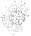
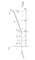
- the front fragmentary view of FIG. The figure which shows an example of a twist characteristic.
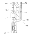
- the fragmentary sectional view which shows a stopper mechanism.
- FIG. 2 is an enlarged partial view of FIG. 1.
- FIG. 1 and 2 show a clutch disk assembly 1 having a damper disk assembly according to an embodiment of the present invention.
- FIG. 1 is a sectional view of the clutch disk assembly 1
- FIG. 2 is a front view thereof.
- the clutch disk assembly 1 is used in a vehicle clutch device and has a clutch function and a damper function.
- OO is a rotation axis of the clutch disk assembly 1, that is, a rotation center line.
- an engine and a flywheel (not shown) are arranged on the left side of FIG. 1
- a transmission (not shown) is arranged on the right side of FIG.
- the R1 side in FIG. 2 is the rotational direction drive side (positive side) of the clutch disk assembly 1, and is the opposite side (negative side) from the R2 side.
- the clutch disk assembly 1 mainly includes an input side plate 2, an output unit 3, a high rigidity damper unit 4, a first low rigidity damper unit 5, a second low rigidity damper unit 6, and a first hysteresis torque.
- a generation mechanism 7, a second hysteresis torque generation mechanism 8, and an intermediate hysteresis torque generation mechanism 9 are provided.
- the clutch disc assembly 1 has a torsional characteristic as shown in FIG. 3 (here, only the positive side torsional characteristic will be described). That is, the first stage angle region L1 in the low twist angle region L (for example, 0 to 17 °) has the characteristic CL1, and the second stage angle region L2 has the characteristic CL2.
- the third step angle region H3 in the high torsion angle region H has the characteristic CH3
- the fourth step angle region H4 has the characteristic CH4
- the fifth step angle region H5 has the characteristic CH5.
- the specific values of the twist angle shown in FIG. 3 and the twist angle shown below are merely examples.
- the input side plate 2 is a portion to which torque from a flywheel (not shown) is input, and includes a clutch plate (second input plate) 11, a retaining plate (first input plate) 12, and a clutch disk 13. And have.
- the clutch plate 11 and the retaining plate 12 are annular disk members, and are arranged at predetermined intervals in the axial direction.
- the clutch plate 11 is disposed on the engine side, and the retaining plate 12 is disposed on the transmission side.
- the clutch plate 11 and the retaining plate 12 are fixed to each other by a part of the retaining plate 12 constituting the stopper mechanism 15 described later, and are relatively immovable in the axial direction and the rotational direction.
- window holes 11a and 12a are formed at equal intervals in the rotation direction on the outer periphery of the clutch plate 11 and the retaining plate 12, respectively.
- raised portions are formed on the inner peripheral side and the outer peripheral side, respectively.
- the inner peripheral end portion of the clutch plate 11 is bent so as to open to the engine side, thereby forming a pressure contact portion 11b.
- a plurality of internal teeth 12 b are formed at the inner peripheral end of the retaining plate 12.
- the clutch disk 13 is a portion that is pressed against a flywheel (not shown).
- the clutch disk 13 has the same configuration as that of a known configuration, and includes a cushioning plate 13a and friction facings 13b fixed to both surfaces of the cushioning plate 13a. A detailed description of the clutch disk 13 is omitted.
- the output unit 3 is disposed between the clutch plate 11 and the retaining plate 12 in the axial direction, and is rotatable relative to the clutch plate 11 and the retaining plate 12.
- the output unit 3 includes a hub (output-side member) 17 disposed on the inner peripheral portion of the clutch plate 11 and the retaining plate 12, and a flange (input-side member) 18 extending radially outward from the hub 17.
- the hub 17 and the flange 18 are separated from each other, and are relatively rotatable within a predetermined angular range (17 ° in this example).
- the hub 17 is a cylindrical member. On the outer peripheral surface, the hub 17 has a large-diameter portion 21 formed at the axial center portion, and a first small-diameter portion 22 and a second small-diameter portion 23 formed at both end portions in the axial direction. And have.
- the first small diameter portion 22 is formed on the retaining plate 12 side of the large diameter portion 21, and the second small diameter portion 23 is formed on the clutch plate 11 side of the large diameter portion 21.
- a plurality of external teeth 21 a are formed on the outer peripheral surface of the large diameter portion 21.
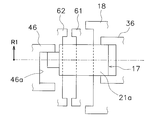
- the external teeth 21 a of the large diameter portion 21 are formed over the entire length of the large diameter portion 21 in the axial direction. However, as shown in the schematic diagrams of FIGS.
- a spline hole 17 a is formed in the inner peripheral surface of the hub 17. The spline hole 17a can be engaged with an input shaft of a transmission (not shown).
- the flange 18 is a substantially disk-shaped member, and a hole 24 into which the hub 17 is inserted is formed at the center.
- a plurality of internal teeth 24 a are formed in the hole 24.
- the plurality of inner teeth 24a can mesh with the outer teeth 21a formed on the large diameter portion 21 of the hub 17.
- the circumferential length of the inner teeth 24a is longer than the circumferential length of the outer teeth 21a. That is, a gap is formed between both end faces of the inner teeth 24a and the outer teeth 21a, and this gap corresponds to an angular range (17 °) in which the flange 18 and the hub 17 can be rotated relative to each other. .
- Each spring accommodating portion 25 is formed with an opening 25 a for accommodating the high-rigidity damper unit 4.
- the opening 25 a is disposed at a position corresponding to the four window holes 11 a and 12 a of the clutch plate 11 and the retaining plate 12.
- an engagement recess 25b that is recessed toward the inner periphery is formed at the center in the circumferential direction.
- a stopper projection 25c is formed on the outer peripheral surface of the spring accommodating portion 25 at the center in the circumferential direction.
- the stopper mechanism 15 is a mechanism for restricting relative rotation of the clutch plate 11 and the retaining plate 12 and the flange 18.
- the stopper mechanism 15 includes a stopper portion 12 c (see FIG. 5) formed on the retaining plate 12 and a stopper protrusion 25 c formed on the flange 18.
- bent portions are formed at equal intervals in the rotation direction on the outer peripheral portion of the retaining plate 12.
- the bent portion is formed by bending a portion provided by extending the outer peripheral portion of the retaining plate 12 toward the outer peripheral side toward the clutch plate 11 and further bending toward the inner peripheral side. That is, the bent portion includes a stopper portion 12c formed by bending from the outer peripheral portion of the retaining plate 12 to the clutch plate 11 side, a fixing portion 12d formed by further bending the tip of the stopper portion 12c to the inner peripheral side, have.
- the fixing portion 12 d is fixed to the clutch plate 11 together with the clutch disk 13 by a rivet 27.
- the fixed portion 12d and the rivet 27 are disposed between the flange 18 and the clutch plate 11 in the axial direction, and interfere with each other when the clutch plate 11 and the retaining plate 12 rotate with respect to the flange 18. It is supposed not to.
- the stopper portion 12 c can be rotated along the outer peripheral surface of the spring accommodating portion 25 of the flange 18. This rotation is regulated by the stopper portion 12c coming into contact with the circumferential end surface of the stopper projection 25c of the flange 18.
- the clutch plate 11 and the retaining plate 12 can rotate relative to the flange 18 between the adjacent stopper protrusions 25c.
- relative rotation of the clutch plate 11 and the retaining plate 12 with respect to the flange 18 is restricted to an angular range between the adjacent stopper projections 25c.
- the high-rigidity damper unit 4 elastically connects the clutch plate 11 and the retaining plate 12 and the flange 18 in the rotational direction, and operates within a range of a high torsion angle region H (see FIG. 3) of torsional characteristics. .
- the high-rigidity damper unit 4 includes four sets of spring units 4 a and is accommodated in the openings 25 a of the flanges 18. Each spring unit 4 a is restricted from moving in the radial direction and the axial direction by the window holes 11 a and 12 a of the clutch plate 11 and the retaining plate 12.
- Each spring unit 4a has a first spring 31 for high rigidity, a second spring 32 for high rigidity, a resin elastic member 33, and a pair of spring seats 34.
- the first spring 31 for high rigidity is composed of a coil spring having relatively high rigidity, and the coil length is substantially the same as the circumferential length of the opening 25 a of the spring accommodating portion 25. And the inner peripheral side of the both ends of the 1st spring 31 is contact
- a gap is provided on the outer peripheral side of both ends of the first spring 31 between the end face in the circumferential direction of the opening 25 a of the flange 18 and the end faces of the window holes 11 a and 12 a of the clutch plate 11 and the retaining plate 12. Yes. Further, both ends of the first spring 31 can be brought into contact with both end faces of the opening 25a in the circumferential direction.
- the resin elastic member 33 is arranged further on the inner peripheral side of the second spring 32, and its length is shorter than the coil length of the second spring 32.
- One pair of spring seats 34 is fitted into recesses 25d (see FIG. 4) formed at both ends of the opening 25a in the circumferential direction, and the other end extends to the inside of the second spring 32. The both ends of the second spring 32 are supported.
- the torsional characteristics are compared until the outer peripheral portion contacts the end surface of the opening 25a after the inner peripheral portion of the first spring 31 contacts the end surface of the opening 25a of the flange 18. After the entire end face of the first spring 31 comes into contact with the end face of the opening 25a, the rigidity is further increased.
- the first low-rigidity damper unit 5 elastically connects the flange 18 and the hub 17 in the rotational direction. As shown in FIG. 3, the first-stage angle in the low-torsion angle region L of torsional characteristics. It operates in the region L1 and the second stage angle region L2. That is, the first low-rigidity damper unit 5 has lower rigidity than the high-rigidity damper unit 4.
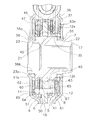
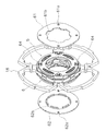
- the first low-rigidity damper unit 5 is disposed between the flange 18 and the inner peripheral portion of the retaining plate 12, and as shown in FIGS. 6 and 8, a pair of first holder plates 35, 1 drive plate 36 and first spring 37 for low rigidity.
- the pair of first holder plates 35 are annular members, and a hole into which the hub 17 is inserted is formed in the inner peripheral portion.
- the pair of first holder plates 35 includes a first engagement plate 40 disposed on the flange 18 side, and a first cover plate 41 disposed to face the first engagement plate 40 in the axial direction. is doing.
- the first engagement plate 40 has engagement claws 40a at four locations on the outer peripheral surface.
- the engagement claw 40a protrudes toward the flange 18 and engages with the engagement recess 25b of the flange 18 without a gap. Therefore, the first engagement plate 40 is not rotatable relative to the flange 18.
- a fixing projection 40b is formed between two adjacent engaging claws 40a.
- the fixing protrusion 40b protrudes to the outer periphery.
- the first engagement plate 40 has four spring accommodating openings 40c, and four arc-shaped long holes 40d are formed between the rotation directions of the openings 40c.
- the first cover plate 41 has fixing claws 41a at four locations on the outer peripheral surface.
- the fixing claw 41 a is formed at a position corresponding to the fixing protrusion 40 b of the first engagement plate 40 and extends to the first engagement plate 40 side.
- the first cover plate 41 can be fixed to the first engagement plate 40 with a gap in the axial direction. Is possible.
- the first cover plate 41 has an opening 41c and a long hole 41d having the same shape at positions corresponding to the opening 40c and the long hole 40d of the first engagement plate 40, respectively.
- the first drive plate 36 is an annular member, and the hub 17 is inserted into the inner periphery.
- a plurality of internal teeth 36 a are formed on the inner peripheral edge of the first drive plate 36.
- a portion on the first small diameter portion 22 side of the outer teeth 21a of the large diameter portion 21 of the hub 17 is engaged with the inner teeth 36a without any gap. Accordingly, the first drive plate 36 cannot rotate relative to the hub 17 and rotates in synchronization with each other.
- the first drive plate 36 has four spring accommodating openings 36c. Moreover, notches 36d are formed at positions corresponding to the long holes 40d and 41d of the plates 40 and 41 other than the portion where the opening 36c is formed.
- the first spring 37 for low rigidity elastically connects the pair of first holder plate 35 and first drive plate 36 in the rotational direction.
- the first spring 37 is accommodated in the opening 36c of the first drive plate 36, and is supported by the openings 40c and 41c of the pair of first holder plates 35 to restrict movement in the axial direction and the radial direction.
- the second low-rigidity damper unit 6 elastically connects the flange 18 and the hub 17 in the rotational direction. As shown in FIG. 3, the second low-rigidity damper unit 6 has a second stage L2 in the low torsion angle region L of torsion characteristics. Operate. That is, the second low-rigidity damper unit 6 operates later than the first low-rigidity damper unit 5 and has lower rigidity than the high-rigidity damper unit 4.
- the second low-rigidity damper unit 6 is disposed between the flange 18 and the inner peripheral portion of the clutch plate 11, and as shown in FIGS. 7 and 8, a pair of second holder plates 45 and a second drive A plate 46 and a low-rigidity second spring 47 are provided.
- the pair of second holder plates 45 are annular members, and a hole into which the hub 17 is inserted is formed in the inner peripheral portion.
- the pair of second holder plates 45 includes a second engagement plate 50 disposed on the flange 18 side, and a second cover plate 51 disposed opposite to the second engagement plate 50 in the axial direction. is doing.
- the second engagement plate 50 has engagement claws 50a at four locations on the outer peripheral surface.
- the engaging claw 50a protrudes toward the flange 18 and engages with the engaging recess 25b of the flange 18 without a gap. Accordingly, the second engagement plate 50 cannot rotate relative to the flange 18.
- a fixing projection 50b is formed between two adjacent engaging claws 50a.
- the fixing protrusion 50b protrudes to the outer periphery.
- the second engagement plate 50 has four spring accommodating openings 50c, and four arc-shaped long holes 50d are formed between the rotation directions of the openings 50c.
- the second cover plate 51 has fixing claws 51a at four locations on the outer peripheral surface.
- the fixing claw 51a is formed at a position corresponding to the fixing protrusion 50b of the second engagement plate 50 and extends to the second engagement plate 50 side.
- the second cover plate 51 can be fixed to the second engagement plate 50 with a gap in the axial direction. Is possible.
- the second cover plate 51 is formed with openings 51c and long holes 51d having the same shape at positions corresponding to the openings 50c and long holes 50d of the second engagement plate 50, respectively.
- the second drive plate 46 is an annular member, and the hub 17 is inserted into the inner peripheral portion.
- a plurality of internal teeth 46 a are formed on the inner peripheral edge of the second drive plate 46.
- a portion (a portion having a narrow tooth width) on the second small diameter portion 23 side of the external teeth 21a of the large diameter portion 21 of the hub 17 is inserted into the internal teeth 46a through a predetermined gap.
- the predetermined gap is formed when the tooth width of the outer teeth 21a meshing with the inner teeth 46a of the second drive plate 46 is narrower than other portions. Therefore, the second drive plate 46 can rotate relative to the hub 17 by an angle corresponding to the gap (in this example, 7 °).
- the second drive plate 46 is formed with four spring accommodating openings 46c. In addition to the portion where the opening 46c is formed, a notch 46d is formed at a position corresponding to the long holes 50d and 51d of the plates 50 and 51.
- ⁇ Second spring 47 for low rigidity> The low rigidity second spring 47 elastically connects the pair of second holder plate 45 and second drive plate 46 in the rotational direction.
- the second spring 47 is accommodated in the opening 46c of the second drive plate 46, and is supported by the openings 50c and 51c of the pair of second holder plates 45 to restrict movement in the axial direction and the radial direction.
- the first hysteresis torque generating mechanism 7 generates the first hysteresis torque HT1 in the angle region L1 of the first low-rigidity damper unit 5. Specifically, the first hysteresis torque generating mechanism 7 generates the lowest first hysteresis torque HT1 in the first stage angle region L1 (0 to 7 ° in this example) of the low torsion angle region L.
- the first hysteresis torque generating mechanism 7 includes a first bush 55 disposed on the outer peripheral portion of the first small diameter portion 22 of the hub 17 and a first bush disposed on the outer peripheral portion of the second small diameter portion 23. 2 bushes 56.
- the first bush 55 is a cylindrical member made of resin, and is rotatable relative to the hub 17. As shown in FIGS. 2 and 4, a plurality of external teeth 55 a are formed on the outer peripheral surface of the first bush 55. The plurality of external teeth 55a are engaged with the plurality of internal teeth 12b formed on the inner peripheral surface of the retaining plate 12, and the retaining plate 12 and the first bush 55 are not rotatable relative to each other. For this reason, when the retaining plate 12 and the hub 17 rotate relative to each other, the side surface on the engine side of the first bush 55 comes into sliding contact with the side surface of the large-diameter portion 21 of the hub 17 to generate a hysteresis torque that is a friction torque.
- the second bush 56 is an annular member made of resin. As shown in FIG. 8, a spherical friction surface 56 a is formed on the engine side surface of the second bushing 56, and the friction surface 56 a is in contact with the pressure contact portion 11 b of the clutch plate 11. In addition, two pairs of opposing planar portions 23 a are formed on the outer peripheral surface of the second small diameter portion 23, and a similar planar portion 56 b is formed on the inner peripheral surface of the second bushing 56, so that they are engaged with each other. Match. Accordingly, the second bushing 56 is not rotatable relative to the hub 17.
- the intermediate hysteresis torque generating mechanism 9 generates an intermediate hysteresis torque HTm higher than the first hysteresis torque HT1 on the low torsion angle side in the operation region L2 of the second low-rigidity damper unit 6.
- the intermediate hysteresis torque generating mechanism 9 has an intermediate hysteresis higher than the first hysteresis torque HT1 in a portion excluding a part of the high torsion angle region in the second stage L2 (in this example, 7 to 15.5 °). Torque HTm is generated.
- the second hysteresis torque generating mechanism 8 generates the second hysteresis torque HT2 in the high torsion angle side in the operation region L2 of the second low-rigidity damper unit 6 and in the angle region H of the high-rigidity damper unit 4.
- the second hysteresis torque generating mechanism 8 is provided in the high torsion angle region (15.5 to 17 ° in this example) in the second stage L2 of the low torsion angle region L and in the entire region of the high torsion angle region H.
- the second hysteresis torque HT2 higher than the intermediate hysteresis torque HTm is generated.
- the intermediate hysteresis torque generating mechanism 9 and the second hysteresis torque generating mechanism 8 include a wave spring 60 and first to third friction plates 61 in addition to the first hysteresis torque generating mechanism 7. , 62, 63, four stud pins 64, first and second friction washers 65, 66, and a cone spring 67.
- the wave spring 60 (also shown in FIG. 7) is an elastic member having an annular shape and unevenness formed in the axial direction, and the second drive plate 46 and the second engagement plate of the second low-rigidity damper unit 6. 50.
- Inner teeth 60 a are formed on the inner peripheral edge of the wave spring 60.
- the internal teeth 60a are inserted into the external teeth 21a (parts having a narrow tooth width) formed on the second small diameter portion 23 side of the large diameter portion 21 of the hub 17 via a predetermined gap. That is, the groove width (the length in the circumferential direction) of the inner teeth 60 a is the same as the groove width of the inner teeth 46 a of the second drive plate 46.
- the wave spring 60 can rotate relative to the hub 17 by a predetermined angle range (7 ° in this example).
- the wave spring 60 makes sliding contact between the second drive plate 46 and the second cover plate 51 and between the wave spring 60 and the second engagement plate 50, and a hysteresis torque (friction torque) is applied to these portions. Intermediate hysteresis torque) can be generated.
- the first and second friction plates 61 and 62 are formed in an annular shape and have four holes 61a and 62a at equal intervals in the circumferential direction.
- the first friction plate 61 is disposed between the first low-rigidity damper unit 5 and the retaining plate 12.
- the second friction plate 62 is disposed between the second low-rigidity damper unit 6 and the clutch plate 11.
- a plurality of internal teeth 61 b are formed on the inner peripheral surface of the first friction plate 61.
- the outer teeth 21a of the hub 17 are inserted into the inner teeth 61b, but a gap corresponding to a predetermined angle (15.5 ° in this example) is formed between the inner teeth 61b and the outer teeth 21a.
- the tooth width (the length in the circumferential direction) of the inner teeth 61 b is formed to be narrower than the tooth width of the inner teeth 24 a of the flange 18.
- the inner peripheral surface of the second friction plate 62 is bent toward the flange 18 in the axial direction, and a plurality of notches 62b are formed in the bent portion.
- the outer teeth 21a of the hub 17 are inserted into the plurality of notches 62b, and the width (circumferential length) of the notches 62b is formed to be narrower than the tooth width of the inner teeth 24a of the flange 18. Yes.
- the first friction plate 61 and the second friction plate 62 are fixed to each other by four stud pins 64 so as not to move in the axial direction and the rotational direction.
- the stud pin 64 passes through arc-shaped long holes and notches 40d, 36d, 41d, 50d, 46d, and 51d formed in the plates of the first and second low-rigidity damper units 5 and 6. Therefore, the first and second friction plates 61 and 62 and the first and second low-rigidity damper units 5 and 6 can be relatively rotated within a predetermined angle range.
- a first friction washer 65 made of, for example, resin is disposed on the side of the retaining plate 12 of the first friction plate 61, and the third friction plate 63 and the cone are interposed between the first friction washer 65 and the retaining plate 12.
- a spring 67 is arranged.
- the cone spring 67 is assembled in a compressed state.
- a second friction washer 66 made of, for example, resin is disposed between the second friction plate 62 and the clutch plate 11.
- the first and second friction washers 65 and 66 are not limited to resin.
- a plurality of claws 63 a bent toward the retaining plate 12 are formed on the outer periphery of the third friction plate 63.
- the claw 63a engages with a hole 12e formed in the retaining plate 12, and relative rotation between the third friction plate 63 and the retaining plate 12 is prohibited.
- the first and second low-rigidity damper units 5 and 6 and the first and second friction plates 61 and 62 are unitized by a stud pin 64, and the axial direction of this unit depends on the length of the stud pin 64.
- the length has been determined.
- the axial length determined by the stud pin 64 is longer than the total length of the axial lengths (thicknesses) of the members and flanges constituting the unit. Therefore, in this unit, in the region where the unit operates integrally (high torsion angle region), no load is applied to the friction plates 61 and 62, and in principle, no hysteresis torque is generated.
- first stage angle L1> When the clutch plate 11 and the retaining plate 12 on the input side are twisted to the R1 side with respect to the hub 17 on the output side, the rigidity of the high-rigidity damper unit 4 is high. Therefore, the first and second low-rigidity damper units 5 , 6 are activated first. That is, the clutch plate 11, the retaining plate 12, the spring unit 4 a, and the flange 18 rotate integrally, and these rotations are applied to the first low-rigidity damper unit 5 and the second low-rigidity damper unit 6 that engage with the flange 18. Communicated.
- the first drive plate 36 (inner teeth 36a) of the first low-rigidity damper unit 5 and the large-diameter portion 21 (outer teeth 21a) of the hub 17 are engaged with no gap. is doing.
- the tooth width of the outer teeth 21a of the large diameter portion 21 with which the second drive plate 46 (inner teeth 46a) of the second low-rigidity damper unit 6 engages is narrowed, the second low-rigidity damper unit 6
- the second drive plate 46 is allowed to rotate relative to the hub 17 by a predetermined angle (7 °). Therefore, when the torsion angle is in the range of 0 to 7 °, only the first low-rigidity spring 37 of the first low-rigidity damper unit 5 operates and, as shown in FIG. CL1 is shown.
- a hysteresis torque is generated between the first bush 55 that rotates in synchronization with the retaining plate 12 and the side surface of the large-diameter portion 21 of the hub 17, and the second bush 56 that rotates in synchronization with the hub 17.
- Hysteresis torque is generated between the friction surface 56 a of the clutch plate 11 and the pressure contact portion 11 b of the clutch plate 11.
- the characteristics of the first hysteresis torque HT1 that is low rigidity by the first spring 37 for low rigidity and relatively low by the first bush 55 and the second bush 56 are obtained.
- Second stage angle region L2> When the twist angle is increased to 7 °, the second drive plate 46 (inner teeth 46a) of the second low-rigidity damper unit 6 and the large-diameter portion 21 (outer teeth 21a) of the hub 17 as shown in FIG. Engage.
- the second low-rigidity spring 47 of the second low-rigidity damper unit 6 also operates. Accordingly, the torsional characteristics in this region are higher than the rigidity of the first-stage characteristics CL1. This operation continues until the flange 18 and the hub 17 abut (up to 17 °).
- the wave spring 60 inner teeth 60a
- the large diameter portion 21 outer teeth 21a
- the second drive plate 46 and the second cover plate 51 and the wave spring 60 and the second engagement plate 50 are in sliding contact with each other, and hysteresis torque (intermediate hysteresis torque HTm) is generated in these portions. To do.
- This intermediate hysteresis torque HTm is higher than the first hysteresis torque HT1.
- the second hysteresis torque HT2 higher than the first hysteresis torque HT1 and the intermediate hysteresis torque HTm is generated.
- the characteristic CL2 has higher rigidity than the rigidity of the first stage characteristic CL1 by the first and second springs 37 and 47 for low rigidity. Further, the intermediate hysteresis torque HTm higher than the first hysteresis torque HT1 is obtained on the low torsion angle side of the second stage angle region L2, and the second hysteresis torque HT2 higher than the first hysteresis torque HT1 is obtained on the high torsion angle side.
- third stage angle region H3> When the twist angle is 17 ° or more, as shown in FIG. 13, the hub 17 and the flange 18 rotate together, so that relative rotation occurs between the clutch plate 11 and the retaining plate 12 and the flange 18. . For this reason, the high-rigidity damper unit 4 operates in an angle region where the twist angle is 17 ° or more.
- the end face of the first spring 31 for high rigidity is initially in contact with the end face in the circumferential direction of the opening 25 a of the flange 18 only on the inner peripheral side.
- the outer peripheral portion of the first spring 31 also comes into contact with the circumferential end face of the opening 25a, and thereafter, the entire end face of the first spring 31 is the circumference of the opening 25a. It will contact
- the second step angle region H2 has rigidity higher than the rigidity of the characteristic CL2 of the second step angle region L2.
- a characteristic CH3 having a hysteresis torque HT2 is obtained.
- the characteristic CH4 having the second hysteresis torque HT2 is obtained with higher rigidity than that of the third stage angle region H3.
- the characteristic CH5 having the second hysteresis torque HT2 is obtained with higher rigidity than that of the fourth stage angle region H4.
- the stopper mechanism 15 operates. That is, the stopper portion 12c of the retaining plate 12 abuts on the stopper protrusion 25c of the flange 18, and further relative rotation is prohibited.
- the first and second low-rigidity damper units 5 and 6 operate within a low torsion angle region. In this case, noise can be suppressed by realizing low rigidity and low hysteresis torque in a wide angle region.
- the second hysteresis torque HT2 in the traveling region is generated on the high torsion angle side of the low torsion angle region, that is, on the high torsion angle side of the region that operates mainly during idling. For this reason, when shifting from the second stage angle area L2 to the third stage angle area H3, the transition can be made smoothly, and tip-in and tip-out can be improved.
- the width of the external teeth 21a of the hub 17 with which the second low-rigidity damper unit 6 is engaged is narrowed.
- the width of the outer teeth 21a of the hub 17 may be made the same as the others, and the width of the inner teeth 46a of the second drive plate 46 of the second low-rigidity damper unit 6 may be increased.
- the intermediate hysteresis torque HTm higher than the first hysteresis torque HT1 is generated in the second stage angle region L2, but the first hysteresis is the same as in the first stage angle region L1.
- the torque HT1 may be generated.
- the low torsion angle region can be widened to attenuate abnormal noise and vibration during idling, and high torque can be obtained during idling in the low torsion angle region.
Landscapes
- Engineering & Computer Science (AREA)
- General Engineering & Computer Science (AREA)
- Mechanical Engineering (AREA)
- Physics & Mathematics (AREA)
- Acoustics & Sound (AREA)
- Aviation & Aerospace Engineering (AREA)
- Mechanical Operated Clutches (AREA)
Abstract
Description
図1及び図2に本発明の一実施形態によるダンパディスク組立体を有するクラッチディスク組立体1を示している。図1はクラッチディスク組立体1の断面図であり、図2はその正面図である。このクラッチディスク組立体1は、車輌のクラッチ装置に用いられ、クラッチ機能とダンパ機能とを有している。図1においてO-Oがクラッチディスク組立体1の回転軸すなわち回転中心線である。また、図1の左側にエンジン及びフライホイール(図示せず)が配置され、図1の右側にトランスミッション(図示せず)が配置されている。さらに、図2のR1側がクラッチディスク組立体1の回転方向駆動側(正側)であり、R2側からその反対側(負側)である。
入力側プレート2は、フライホイール(図示せず)からのトルクが入力される部分であり、クラッチプレート(第2入力プレート)11と、リティニングプレート(第1入力プレート)12と、クラッチディスク13と、を有している。
クラッチプレート11及びリティニングプレート12は、環状の円板部材であり、軸方向に所定の間隔を空けて配置されている。クラッチプレート11はエンジン側に配置され、リティニングプレート12はトランスミッション側に配置されている。クラッチプレート11及びリティニングプレート12は、後述するストッパ機構15を構成するリティニングプレート12の一部によって互いに固定され、軸方向及び回転方向に相対的に移動不能である。
クラッチディスク13は図示しないフライホイールに押し付けられる部分である。クラッチディスク13は、周知の構成と同様であり、クッショニングプレート13aと、クッショニングプレート13aの両面に固定された摩擦フェーシング13bと、から構成されている。このクラッチディスク13についての詳細な説明は省略する。
出力ユニット3は、クラッチプレート11とリティニングプレート12との軸方向間に配置され、クラッチプレート11及びリティニングプレート12に対して相対回転自在である。この出力ユニット3は、クラッチプレート11及びリティニングプレート12の内周部に配置されたハブ(出力側部材)17と、ハブ17から径方向外方に延びるフランジ(入力側部材)18と、を有している。ハブ17とフランジ18とは分離されており、所定の角度範囲(この例では17°)で相対回転自在である。
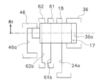
ハブ17は、円筒形の部材であり、外周面には、軸方向中央部に形成された大径部21と、軸方向の両端部に形成された第1小径部22及び第2小径部23と、を有している。第1小径部22は大径部21のリティニングプレート12側に形成され、第2小径部23は大径部21のクラッチプレート11側に形成されている。大径部21の外周面には複数の外歯21aが形成されている。大径部21の外歯21aは、大径部21の軸方向の全長にわたって形成されている。しかし、図10~図13の模式図で示すように、外歯21aにおいて、軸方向中央部と第1小径部22側における歯幅は同じであるが、第2小径部23側の歯幅は他の部分より狭くなっている(この例では、捩り角度にして7°分だけ狭い)。また、ハブ17の内周面にはスプライン孔17aが形成されている。スプライン孔17aは、図示しないトランスミッションの入力軸に係合可能である。
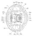
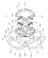
フランジ18は、図4に分解して示すように、概略円板状の部材であり、中心部にはハブ17が挿入された孔24が形成されている。孔24には複数の内歯24aが形成されている。この複数の内歯24aに、ハブ17の大径部21に形成された外歯21aが噛み合い可能である。内歯24aの円周方向の長さは外歯21aの円周方向長さより長くなっている。すなわち、内歯24aの両端面と外歯21aとの間には隙間が形成されており、この隙間が、フランジ18とハブ17との相対回転可能な角度範囲(17°)に相当している。
ストッパ機構15は、クラッチプレート11及びリティニングプレート12とフランジ18との相対回転を規制するための機構である。ストッパ機構15は、リティニングプレート12に形成されたストッパ部12c(図5参照)と、フランジ18に形成されたストッパ用突起25cとによって構成されている。
高剛性ダンパユニット4は、クラッチプレート11及びリティニングプレート12とフランジ18とを回転方向に弾性的に連結するものであり、捩り特性の高捩り角度領域H(図3参照)の範囲で作動する。高剛性ダンパユニット4は、図2に示すように、4組のスプリングユニット4aからなり、それぞれフランジ18の開口25aに収容されている。そして、各スプリングユニット4aは、クラッチプレート11及びリティニングプレート12の窓孔11a,12aによって径方向及び軸方向の移動が規制されている。
第1低剛性ダンパユニット5は、フランジ18とハブ17とを回転方向に弾性的に連結するものであり、図3に示すように、捩り特性の低捩り角度領域Lのうちの1段目角度領域L1及び2段目角度領域L2で作動する。すなわち、第1低剛性ダンパユニット5は高剛性ダンパユニット4より剛性が低い。第1低剛性ダンパユニット5は、フランジ18とリティニングプレート12の内周部との間に配置されており、図6及び図8に示すように、1対の第1ホルダプレート35と、第1ドライブプレート36と、低剛性用第1スプリング37と、を有している。
1対の第1ホルダプレート35は、環状の部材であり、内周部にはハブ17が挿入される孔が形成されている。1対の第1ホルダプレート35は、フランジ18側に配置された第1係合プレート40と、第1係合プレート40と軸方向に対向して配置された第1カバープレート41と、を有している。
第1ドライブプレート36は、環状の部材であり、内周部にはハブ17が挿入される。第1ドライブプレート36の内周端縁には複数の内歯36aが形成されている。この内歯36aに、ハブ17の大径部21の外歯21aにおける第1小径部22側の部分が隙間なく係合している。したがって、第1ドライブプレート36はハブ17に対して相対回転不能であって互いに同期して回転する。
低剛性用第1スプリング37は、1対の第1ホルダプレート35と第1ドライブプレート36とを回転方向に弾性的に連結する。第1スプリング37は第1ドライブプレート36の開口36cに収容されており、1対の第1ホルダプレート35の開口40c,41cによって支持されて軸方向及び径方向の移動が規制されている。
第2低剛性ダンパユニット6はフランジ18とハブ17とを回転方向に弾性的に連結するものであり、図3に示すように、捩り特性の低捩り角度領域Lのうちの2段目L2で作動する。すなわち、第2低剛性ダンパユニット6は、第1低剛性ダンパユニット5より遅れて作動し、高剛性ダンパユニット4より剛性が低い。第2低剛性ダンパユニット6は、フランジ18とクラッチプレート11の内周部と間に配置されており、図7及び図8に示すように、1対の第2ホルダプレート45と、第2ドライブプレート46と、低剛性用第2スプリング47と、を有している。
1対の第2ホルダプレート45は、環状の部材であり、内周部にはハブ17が挿入される孔が形成されている。1対の第2ホルダプレート45は、フランジ18側に配置された第2係合プレート50と、第2係合プレート50と軸方向に対向して配置された第2カバープレート51と、を有している。
第2ドライブプレート46は、環状の部材であり、内周部にはハブ17が挿入される。第2ドライブプレート46の内周端縁には複数の内歯46aが形成されている。この内歯46aに、ハブ17の大径部21の外歯21aにおける第2小径部23側の部分(歯幅の狭い部分)が所定の隙間を介して挿入されている。この所定の隙間は、第2ドライブプレート46の内歯46aと噛み合う外歯21aの歯幅が他の部分より狭いことによって形成されるものである。したがって、第2ドライブプレート46はハブ17に対してこの隙間に相当する角度分(この例では7°)だけ相対回転が可能である。
低剛性用第2スプリング47は、1対の第2ホルダプレート45と第2ドライブプレート46とを回転方向に弾性的に連結する。第2スプリング47は第2ドライブプレート46の開口46cに収容されており、1対の第2ホルダプレート45の開口50c,51cによって支持されて軸方向及び径方向の移動が規制されている。
第1ヒステリシストルク発生機構7は、第1低剛性ダンパユニット5の角度領域L1において第1ヒステリシストルクHT1を発生する。具体的には、第1ヒステリシストルク発生機構7は、低捩り角度領域Lの1段目角度領域L1(この例では0~7°)において、最も低い第1ヒステリシストルクHT1を発生する。
中間ヒステリシストルク発生機構9は、第2低剛性ダンパユニット6の作動領域L2における低捩り角度側において第1ヒステリシストルクHT1より高い中間ヒステリシストルクHTmを発生する。具体的には、中間ヒステリシストルク発生機構9は、2段目L2における高捩り角度領域の一部を除く部分(この例では7~15.5°)において、第1ヒステリシストルクHT1より高い中間ヒステリシストルクHTmを発生する。
ここでは、正側に捩れるときの動作について、捩り特性線図及び図10~図13の模式図を用いて説明し、負側の捩り特性については省略する。
出力側のハブ17に対して、入力側のクラッチプレート11及びリティニングプレート12がR1側に捩れると、高剛性ダンパユニット4の剛性が高いために、第1及び第2低剛性ダンパユニット5,6が先に作動する。すなわち、クラッチプレート11、リティニングプレート12、スプリングユニット4a、及びフランジ18は一体で回転し、これらの回転はフランジ18に係合する第1低剛性ダンパユニット5及び第2低剛性ダンパユニット6に伝達される。具体的には、フランジ18の係合凹部25bと、両低剛性ダンパユニット5,6の第1及び第2係合プレート40,50の係合爪40a,50aと、の噛み合いによって、フランジ18から両低剛性ダンパユニット5,6にトルクが伝達される。
捩り角度が大きくなって7°になると、図11に示すように、第2低剛性ダンパユニット6の第2ドライブプレート46(内歯46a)とハブ17の大径部21(外歯21a)とが係合する。これにより、第1低剛性ダンパユニット5の低剛性用第1スプリング37に加えて、第2低剛性ダンパユニット6の低剛性用第2スプリング47も作動する。したがって、この領域の捩り特性は1段目の特性CL1の剛性よりは高い剛性となる。この作動は、フランジ18とハブ17とが当接するまで(17°まで)続く。
捩り角度が17°以上になると、図13に示すように、ハブ17とフランジ18とが一体となって回転するので、クラッチプレート11及びリティニングプレート12とフランジ18との間に相対回転が生じる。このため、捩り角度が17°以上の角度領域では、高剛性ダンパユニット4が作動することになる。ここで、4組のスプリングユニット4aにおいて、高剛性用第1スプリング31の端面は、当初は内周側のみがフランジ18の開口25aの円周方向端面に当接している。そして、捩り角度が大きくなって19°になると、第1スプリング31の外周側部分も開口25aの円周方向端面と当接し、これ以降は第1スプリング31の端面の全面が開口25aの円周方向端面に当接することになる。
捩り角度が19°以上になると、前述のように、第1スプリング31の端面の全面がフランジ18の開口25aに当接することになるので、3段目角度領域H3の剛性よりもさらに高い剛性が得られる。
捩り角度が大きくなって(40.5°)、第1スプリング31及び第2スプリング32が所定量収縮すると、対向するスプリングシート34の端面が樹脂製弾性部材33の両端面に当接する。この角度以降は、第1及び第2スプリング31,32に加えて樹脂製弾性部材33も圧縮されることになる。このため、4段目の剛性よりもさらに高い剛性となる。
車両の前後振動のように振幅の大きな捩り振動が発生すると、捩り特性は正負の高捩り角度領域間で変動を繰り返す。この場合は、比較的高い第2ヒステリシストルクHT2によって車両の前後振動は速やかに減衰される。
本発明は以上のような実施形態に限定されるものではなく、本発明の範囲を逸脱することなく種々の変形又は修正が可能である。
2 入力側プレート
3 出力ユニット
4 高剛性ダンパユニット
5 第1低剛性ダンパユニット
6 第2低剛性ダンパユニット
7 第1ヒステリシストルク発生機構
8 第2ヒステリシストルク発生機構
11 クラッチプレート
12 リティニングプレート
17 ハブ
18 フランジ
35,45 ホルダプレート
36,46 ドライブプレート
37,47 低剛性用スプリング
Claims (7)
- エンジンから入力されるトルク変動を減衰してトランスミッション側に伝達するためのダンパディスク組立体であって、
軸方向において対向して配置されるとともに互いに固定され、エンジンからトルクが入力される第1及び第2入力プレートと、
前記第1及び第2入力プレートと相対回転可能に配置されるとともに互いに相対回転可能な入力側部材及び出力側部材を有し、前記入力側部材は前記第1及び第2入力プレートの軸方向間に配置され、前記出力側部材はトランスミッションに連結可能である、出力ユニットと、
前記第1及び第2入力プレートと前記入力側部材とを回転方向に弾性的に連結するとともに、捩り特性の高捩り角度領域において作動する高剛性ダンパユニットと、
前記入力側部材と前記出力側部材とを回転方向に弾性的に連結するとともに、前記高剛性ダンパユニットの内周側において前記第1入力プレートと前記入力側部材の軸方向間に配置され、捩り特性の低捩り角度領域において作動し、前記高剛性ダンパユニットよりも低剛性の第1低剛性ダンパユニットと、
前記入力側部材と前記出力側部材とを回転方向に弾性的に連結するとともに、前記高剛性ダンパユニットの内周側において前記第2入力プレートと前記入力側部材の軸方向間に配置され、捩り特性の低捩り角度領域において前記第1低剛性ダンパユニットよりも遅れて作動し、前記高剛性ダンパユニットよりも低剛性の第2低剛性ダンパユニットと、
を備えた、ダンパディスク組立体。 - 前記出力側部材はトランスミッションに連結可能なハブであり、
前記入力側部材は前記ハブの外周側に径方向に延びて形成され、前記ハブと所定の角度範囲において相対回転可能なフランジである、
請求項1に記載のダンパディスク組立体。 - 前記高剛性ダンパユニットは前記第1及び第2入力プレートと前記フランジとを回転方向に弾性的に連結するものであり、
前記第1及び第2低剛性ダンパユニットはそれぞれ前記フランジと前記ハブとを回転方向に弾性的に連結するものである、
請求項2に記載のダンパディスク組立体。 - 前記第1及び第2低剛性ダンパユニットはそれぞれ、
前記フランジに係合して前記フランジからトルクが入力される1対のホルダプレートと、
前記1対のホルダプレートの軸方向間に配置されるとともに前記ハブに係合して前記ハブにトルクを出力するドライブプレートと、
前記1対のホルダプレートと前記ドライブプレートとを回転方向に弾性的に連結する弾性部材と、
を有する、
請求項3に記載のダンパディスク組立体。 - 前記第1低剛性ダンパユニットの作動領域及び前記第2低剛性ダンパユニットの作動領域における低捩り角度側において第1ヒステリシストルクを発生する第1ヒステリシストルク発生機構と、
前記第2低剛性ダンパユニットの作動領域における高捩り角度側において、前記第1ヒステリシストルクよりも高い第2ヒステリシストルクを発生する第2ヒステリシストルク発生機構と、
をさらに備えた、請求項1から4のいずれかに記載のダンパディスク組立体。 - 前記第2ヒステリシストルク発生機構は、前記高剛性ダンパユニットの作動領域においても前記第2ヒステリシストルクを発生する、請求項5に記載のダンパディスク組立体。
- 前記第2低剛性ダンパユニットの作動領域における低捩り角度側において、前記第1ヒステリシストルクより大きく前記第2ヒステリシストルクより小さい中間ヒステリシストルクを発生する中間ヒステリシストルク発生機構をさらに備えた、請求項5又は6に記載のダンパディスク組立体。
Priority Applications (3)
| Application Number | Priority Date | Filing Date | Title |
|---|---|---|---|
| US14/914,743 US9964158B2 (en) | 2013-09-03 | 2014-08-29 | Damper disk assembly |
| CN201480045315.6A CN105473883B (zh) | 2013-09-03 | 2014-08-29 | 减振盘组件 |
| DE112014004011.8T DE112014004011T5 (de) | 2013-09-03 | 2014-08-29 | Dämpfungsscheibenanordnung |
Applications Claiming Priority (2)
| Application Number | Priority Date | Filing Date | Title |
|---|---|---|---|
| JP2013182562A JP5705935B2 (ja) | 2013-09-03 | 2013-09-03 | ダンパディスク組立体 |
| JP2013-182562 | 2013-09-03 |
Publications (1)
| Publication Number | Publication Date |
|---|---|
| WO2015033873A1 true WO2015033873A1 (ja) | 2015-03-12 |
Family
ID=52628347
Family Applications (1)
| Application Number | Title | Priority Date | Filing Date |
|---|---|---|---|
| PCT/JP2014/072782 Ceased WO2015033873A1 (ja) | 2013-09-03 | 2014-08-29 | ダンパディスク組立体 |
Country Status (5)
| Country | Link |
|---|---|
| US (1) | US9964158B2 (ja) |
| JP (1) | JP5705935B2 (ja) |
| CN (1) | CN105473883B (ja) |
| DE (1) | DE112014004011T5 (ja) |
| WO (1) | WO2015033873A1 (ja) |
Cited By (1)
| Publication number | Priority date | Publication date | Assignee | Title |
|---|---|---|---|---|
| CN111442035A (zh) * | 2019-01-16 | 2020-07-24 | 株式会社艾科赛迪 | 阻尼器装置 |
Families Citing this family (10)
| Publication number | Priority date | Publication date | Assignee | Title |
|---|---|---|---|---|
| US10055562B2 (en) * | 2013-10-23 | 2018-08-21 | Intel Corporation | Techniques for identifying a change in users |
| JP6141783B2 (ja) | 2014-03-14 | 2017-06-07 | 株式会社エクセディ | ダンパディスク組立体 |
| JP6654162B2 (ja) * | 2017-03-10 | 2020-02-26 | 株式会社エクセディ | ダンパディスク組立体 |
| US10663026B2 (en) * | 2018-10-03 | 2020-05-26 | Check-Mate Industries, Inc. | Belleville washer and Belleville spring |
| JP7227804B2 (ja) * | 2019-03-15 | 2023-02-22 | 株式会社エクセディ | ダンパ装置 |
| JP7267045B2 (ja) * | 2019-03-15 | 2023-05-01 | 株式会社エクセディ | ダンパ装置 |
| JP7340346B2 (ja) * | 2019-04-03 | 2023-09-07 | 株式会社エクセディ | トルクリミッタ付きダンパ装置 |
| US20210190172A1 (en) * | 2019-12-19 | 2021-06-24 | Schaeffler Technologies AG & Co. KG | Torsional vibration damper with a friction plate |
| FR3117563B1 (fr) * | 2020-12-11 | 2024-04-12 | Valeo Embrayages | Module pre-amortisseur avec moyens de verrouillage |
| WO2023030690A1 (en) * | 2021-08-31 | 2023-03-09 | Eaton Intelligent Power Limited | Internal clutch pre-damper with high filtering capacity |
Citations (4)
| Publication number | Priority date | Publication date | Assignee | Title |
|---|---|---|---|---|
| JPH0242213A (ja) * | 1988-06-22 | 1990-02-13 | Valeo | ねじり緩衝装置 |
| JPH10339355A (ja) * | 1997-06-06 | 1998-12-22 | Exedy Corp | サブダンパーユニット、ダンパー装置 |
| JPH11173381A (ja) * | 1997-12-12 | 1999-06-29 | Exedy Corp | ダンパー |
| JP2009019746A (ja) * | 2007-07-13 | 2009-01-29 | Exedy Corp | ダンパー機構 |
Family Cites Families (6)
| Publication number | Priority date | Publication date | Assignee | Title |
|---|---|---|---|---|
| US3129570A (en) | 1960-06-02 | 1964-04-21 | Dana Corp | Clutch driven member |
| FR2624236B1 (fr) * | 1987-12-08 | 1990-04-06 | Valeo | Dispositif amortisseur de torsion a grand debattement angulaire, en particulier friction d'embrayage, notamment pour vehicule automobile |
| US6029793A (en) | 1997-12-12 | 2000-02-29 | Exedy Corporation | Damper disk assembly |
| JP3605507B2 (ja) | 1998-03-30 | 2004-12-22 | 株式会社エクセディ | ダンパー機構 |
| CN102425617B (zh) | 2007-06-01 | 2015-04-01 | 株式会社艾科赛迪 | 减振机构 |
| JP6141783B2 (ja) * | 2014-03-14 | 2017-06-07 | 株式会社エクセディ | ダンパディスク組立体 |
-
2013
- 2013-09-03 JP JP2013182562A patent/JP5705935B2/ja active Active
-
2014
- 2014-08-29 DE DE112014004011.8T patent/DE112014004011T5/de active Pending
- 2014-08-29 WO PCT/JP2014/072782 patent/WO2015033873A1/ja not_active Ceased
- 2014-08-29 US US14/914,743 patent/US9964158B2/en active Active
- 2014-08-29 CN CN201480045315.6A patent/CN105473883B/zh active Active
Patent Citations (4)
| Publication number | Priority date | Publication date | Assignee | Title |
|---|---|---|---|---|
| JPH0242213A (ja) * | 1988-06-22 | 1990-02-13 | Valeo | ねじり緩衝装置 |
| JPH10339355A (ja) * | 1997-06-06 | 1998-12-22 | Exedy Corp | サブダンパーユニット、ダンパー装置 |
| JPH11173381A (ja) * | 1997-12-12 | 1999-06-29 | Exedy Corp | ダンパー |
| JP2009019746A (ja) * | 2007-07-13 | 2009-01-29 | Exedy Corp | ダンパー機構 |
Cited By (1)
| Publication number | Priority date | Publication date | Assignee | Title |
|---|---|---|---|---|
| CN111442035A (zh) * | 2019-01-16 | 2020-07-24 | 株式会社艾科赛迪 | 阻尼器装置 |
Also Published As
| Publication number | Publication date |
|---|---|
| JP5705935B2 (ja) | 2015-04-22 |
| DE112014004011T5 (de) | 2016-05-25 |
| CN105473883A (zh) | 2016-04-06 |
| JP2015048930A (ja) | 2015-03-16 |
| US9964158B2 (en) | 2018-05-08 |
| US20160208862A1 (en) | 2016-07-21 |
| CN105473883B (zh) | 2017-11-24 |
Similar Documents
| Publication | Publication Date | Title |
|---|---|---|
| JP6141783B2 (ja) | ダンパディスク組立体 | |
| JP5705935B2 (ja) | ダンパディスク組立体 | |
| WO2016129519A1 (ja) | ダンパーディスク組立体 | |
| JP2017187067A (ja) | ダンパディスク組立体 | |
| JP7473420B2 (ja) | ダンパ装置 | |
| WO2016129182A1 (ja) | ダンパーディスク組立体 | |
| CN107208707B (zh) | 减震片组件 | |
| JP4445529B2 (ja) | ダンパー機構 | |
| JP2022052126A (ja) | ヒステリシストルク発生機構及び動力伝達装置 | |
| JP2019090428A (ja) | ダンパディスク組立体 | |
| JP2019090428A5 (ja) | ||
| JP6545972B2 (ja) | ダンパーディスク組立体 | |
| JP6654162B2 (ja) | ダンパディスク組立体 | |
| JP2023010399A (ja) | ダンパ装置 | |
| JP2000274487A (ja) | ダンパー機構及びダンパーディスク組立体 | |
| JP6756645B2 (ja) | ダンパディスク組立体 | |
| JP2018150956A (ja) | 車輌用の摩擦発生構造 | |
| JP2020041707A (ja) | ダンパーディスク組立体 | |
| JP2020112241A (ja) | ダンパ装置 | |
| JP3605507B2 (ja) | ダンパー機構 | |
| JP6976874B2 (ja) | 動力伝達構造及び動力伝達装置 | |
| JP2021092246A (ja) | ダンパ装置 | |
| JP2000035053A (ja) | ダンパー機構 | |
| JP2019132288A (ja) | 動力伝達装置 | |
| WO2018047546A1 (ja) | 動力伝達装置 |
Legal Events
| Date | Code | Title | Description |
|---|---|---|---|
| WWE | Wipo information: entry into national phase |
Ref document number: 201480045315.6 Country of ref document: CN |
|
| 121 | Ep: the epo has been informed by wipo that ep was designated in this application |
Ref document number: 14841936 Country of ref document: EP Kind code of ref document: A1 |
|
| WWE | Wipo information: entry into national phase |
Ref document number: 14914743 Country of ref document: US |
|
| WWE | Wipo information: entry into national phase |
Ref document number: 1120140040118 Country of ref document: DE Ref document number: 112014004011 Country of ref document: DE |
|
| 122 | Ep: pct application non-entry in european phase |
Ref document number: 14841936 Country of ref document: EP Kind code of ref document: A1 |