WO2015033792A1 - レーザ光源装置及び画像投影装置 - Google Patents
レーザ光源装置及び画像投影装置 Download PDFInfo
- Publication number
- WO2015033792A1 WO2015033792A1 PCT/JP2014/071893 JP2014071893W WO2015033792A1 WO 2015033792 A1 WO2015033792 A1 WO 2015033792A1 JP 2014071893 W JP2014071893 W JP 2014071893W WO 2015033792 A1 WO2015033792 A1 WO 2015033792A1
- Authority
- WO
- WIPO (PCT)
- Prior art keywords
- laser light
- light
- incident
- light source
- incident surface
- Prior art date
- Legal status (The legal status is an assumption and is not a legal conclusion. Google has not performed a legal analysis and makes no representation as to the accuracy of the status listed.)
- Ceased
Links
Images


Classifications
-
- G—PHYSICS
- G03—PHOTOGRAPHY; CINEMATOGRAPHY; ANALOGOUS TECHNIQUES USING WAVES OTHER THAN OPTICAL WAVES; ELECTROGRAPHY; HOLOGRAPHY
- G03B—APPARATUS OR ARRANGEMENTS FOR TAKING PHOTOGRAPHS OR FOR PROJECTING OR VIEWING THEM; APPARATUS OR ARRANGEMENTS EMPLOYING ANALOGOUS TECHNIQUES USING WAVES OTHER THAN OPTICAL WAVES; ACCESSORIES THEREFOR
- G03B21/00—Projectors or projection-type viewers; Accessories therefor
- G03B21/14—Details
- G03B21/20—Lamp housings
- G03B21/2006—Lamp housings characterised by the light source
- G03B21/2013—Plural light sources
-
- G—PHYSICS
- G02—OPTICS
- G02B—OPTICAL ELEMENTS, SYSTEMS OR APPARATUS
- G02B27/00—Optical systems or apparatus not provided for by any of the groups G02B1/00 - G02B26/00, G02B30/00
- G02B27/09—Beam shaping, e.g. changing the cross-sectional area, not otherwise provided for
- G02B27/0938—Using specific optical elements
- G02B27/0994—Fibers, light pipes
-
- G—PHYSICS
- G02—OPTICS
- G02B—OPTICAL ELEMENTS, SYSTEMS OR APPARATUS
- G02B27/00—Optical systems or apparatus not provided for by any of the groups G02B1/00 - G02B26/00, G02B30/00
- G02B27/10—Beam splitting or combining systems
- G02B27/106—Beam splitting or combining systems for splitting or combining a plurality of identical beams or images, e.g. image replication
-
- G—PHYSICS
- G02—OPTICS
- G02B—OPTICAL ELEMENTS, SYSTEMS OR APPARATUS
- G02B27/00—Optical systems or apparatus not provided for by any of the groups G02B1/00 - G02B26/00, G02B30/00
- G02B27/10—Beam splitting or combining systems
- G02B27/12—Beam splitting or combining systems operating by refraction only
- G02B27/123—The splitting element being a lens or a system of lenses, including arrays and surfaces with refractive power
-
- G—PHYSICS
- G02—OPTICS
- G02B—OPTICAL ELEMENTS, SYSTEMS OR APPARATUS
- G02B27/00—Optical systems or apparatus not provided for by any of the groups G02B1/00 - G02B26/00, G02B30/00
- G02B27/48—Laser speckle optics
-
- G—PHYSICS
- G03—PHOTOGRAPHY; CINEMATOGRAPHY; ANALOGOUS TECHNIQUES USING WAVES OTHER THAN OPTICAL WAVES; ELECTROGRAPHY; HOLOGRAPHY
- G03B—APPARATUS OR ARRANGEMENTS FOR TAKING PHOTOGRAPHS OR FOR PROJECTING OR VIEWING THEM; APPARATUS OR ARRANGEMENTS EMPLOYING ANALOGOUS TECHNIQUES USING WAVES OTHER THAN OPTICAL WAVES; ACCESSORIES THEREFOR
- G03B21/00—Projectors or projection-type viewers; Accessories therefor
- G03B21/14—Details
- G03B21/20—Lamp housings
- G03B21/2006—Lamp housings characterised by the light source
- G03B21/2033—LED or laser light sources
-
- G—PHYSICS
- G03—PHOTOGRAPHY; CINEMATOGRAPHY; ANALOGOUS TECHNIQUES USING WAVES OTHER THAN OPTICAL WAVES; ELECTROGRAPHY; HOLOGRAPHY
- G03B—APPARATUS OR ARRANGEMENTS FOR TAKING PHOTOGRAPHS OR FOR PROJECTING OR VIEWING THEM; APPARATUS OR ARRANGEMENTS EMPLOYING ANALOGOUS TECHNIQUES USING WAVES OTHER THAN OPTICAL WAVES; ACCESSORIES THEREFOR
- G03B21/00—Projectors or projection-type viewers; Accessories therefor
- G03B21/14—Details
- G03B21/20—Lamp housings
- G03B21/208—Homogenising, shaping of the illumination light
-
- H—ELECTRICITY
- H04—ELECTRIC COMMUNICATION TECHNIQUE
- H04N—PICTORIAL COMMUNICATION, e.g. TELEVISION
- H04N9/00—Details of colour television systems
- H04N9/12—Picture reproducers
- H04N9/31—Projection devices for colour picture display, e.g. using electronic spatial light modulators [ESLM]
- H04N9/3141—Constructional details thereof
- H04N9/315—Modulator illumination systems
- H04N9/3161—Modulator illumination systems using laser light sources
Definitions
- the present invention relates to a laser light source device including a plurality of laser light sources that emit laser light, and also relates to an image projection device including the laser light source device.
- a laser light source device in which laser beams emitted from a plurality of laser light sources are incident on an optical fiber or the like is known (for example, Patent Document 1).
- a technique is known in which light emitted from such a laser light source device is used as a light source for an exposure light source device or a projector.
- noise with the intensity of light called speckle noise is generated on the laser light irradiation surface and the retina of the observer.
- Patent Document 1 in order to reduce speckle noise, a laser light source device is proposed in which at least one of the plurality of laser light sources emits light having a wavelength different from that of the other laser light sources. .
- the laser light source device according to Patent Document 1 there is a limit to the range of wavelengths that can be used, and therefore sufficient speckle noise reduction (also referred to as “despeckle effect” or “speckle contrast reduction”) can be obtained. There is a problem that it is not possible.
- a laser light source device includes a plurality of laser light sources that emit laser light, and a light guide having an incident surface on which light emitted from the plurality of laser light sources is incident, and the plurality of lasers At least two laser light sources among the light sources emit light having the same wavelength, and at least two lights of the same wavelength have different incident angles of the optical axis with respect to the incident surface.
- the laser light source device includes a plurality of laser light sources that emit laser light, and an optical system that receives the light emitted from the plurality of laser light sources and emits the light toward the incident surface of the light guide.
- the at least two laser light sources out of the plurality of laser light sources emit light of the same wavelength, and the plurality of laser light sources and the optical system are configured to emit at least two lights of the same wavelength light. It is comprised so that the incident angle of the optical axis with respect to the said entrance plane may differ.
- the light respectively emitted from the plurality of laser light sources is incident on the incident surface of the light guide.
- at least two laser light sources that emit light of the same wavelength are provided, and light emitted from at least two of the laser light sources has different incident angles of the optical axis with respect to the incident surface. ing. Thereby, speckle noise can be reduced.
- the laser light source device may be configured such that the incident angles of the optical axis with respect to the incident surface are all different for the light having the same wavelength.
- At least two laser light sources that emit light of the same wavelength are provided. And in the light radiate
- the light emitted from at least two of the plurality of laser light sources has the same incident angle of the optical axis with respect to the incident surface, and the at least two laser light sources are Alternatively, it may be configured to emit light of different wavelengths.
- At least two laser light sources that emit light having the same incident angle of the optical axis with respect to the incident surface are provided.
- at least two laser light sources emit light of different wavelengths.
- the light guide may be an optical fiber or a rod integrator.
- an image projection apparatus includes at least one laser light source device described above, and uses light emitted from the laser light source device as projection light.
- the present invention has an excellent effect that a sufficient reduction in speckle noise can be obtained.
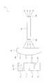
- FIG. 1 is a schematic configuration diagram of an image projection apparatus according to an embodiment of the present invention.
- FIG. 2 is a schematic configuration diagram of the laser light source device according to the embodiment.
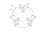
- FIG. 3 is a diagram illustrating an incident pattern of light incident on the optical system according to the embodiment.
- FIG. 4 is a diagram for explaining an incident angle of light on an incident surface of the light guide according to the embodiment.
- FIG. 5 is a diagram illustrating “different wavelengths” according to the embodiment.
- FIG. 6 is a diagram illustrating “different wavelengths” according to the embodiment.
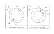
- FIG. 7 is a diagram for explaining an effect when light of the same wavelength is incident on the incident surface of the light guide at different angles, and is a diagram illustrating an incident pattern of light incident on the optical system.
- FIG. 1 is a schematic configuration diagram of an image projection apparatus according to an embodiment of the present invention.
- FIG. 2 is a schematic configuration diagram of the laser light source device according to the embodiment.
- FIG. 3 is a diagram illustrating an incident pattern
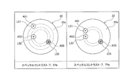
- FIG. 8 is a diagram for explaining an effect when light of different wavelengths is incident on the incident surface of the light guide, and is a diagram illustrating an incident pattern of light incident on the optical system.
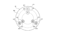
- FIG. 9 is a diagram for explaining an incident pattern of light incident on an optical system according to another embodiment of the present invention.
- FIG. 10 is a diagram illustrating an incident pattern of light incident on an optical system according to still another embodiment of the present invention.
- the image projection apparatus 1 includes a plurality (three in the present embodiment) of laser light source devices 2 (2R, 2G, and 2B) that emit light of different colors. And a spatial modulation element 3 that converts the light emitted from each laser light source device 2 into an optical image.
- the image projection apparatus 1 also combines a color synthesis optical member 4 that synthesizes the light images emitted from the spatial modulation elements 3, and light that projects the light image emitted from the color synthesis optical member 4 on the screen 100. And an image projection mechanism 5.
- the laser light source device 2 includes a first laser light source device 2R that emits laser light of a first color (for example, red) and a second laser light source that emits laser light of a second color (for example, green).
- An apparatus 2G and a third laser light source apparatus 2B that emits laser light of a third color (for example, blue) are provided.
- the spatial modulation element 3 is composed of, for example, a digital micromirror device or a liquid crystal display device
- the color composition optical member 4 is composed of, for example, a color composition prism such as a dichroic prism
- the optical image projection mechanism 5 is composed of, for example, And a projection lens.
- the laser light source device 2 includes a plurality of laser light sources 21 that emit laser light, an optical system 22 that receives light emitted from the plurality of laser light sources 21, and an optical system. And a light guide 23 having an incident surface 23a on which light emitted from the system 22 is incident. In the laser light source device 2, the light emitted from the light guide 23 is incident on the spatial modulation element 3.
- the laser light source 21 includes a semiconductor laser 211 that emits laser light, and a collimator lens 212 that converts the laser light emitted from the semiconductor laser 211 into parallel light.
- the plurality of laser light sources 21 are arranged so that the optical axes of the emitted light are parallel to each other at least when entering the optical system 22.
- the plurality of laser light sources 21 are arranged so that the optical axis of the emitted light is different at the incident surface 22 a of the optical system 22.
- the plurality of laser light sources 21 (particularly, laser light sources 21 that output light of the same wavelength) are arranged so that the emitted light does not overlap with each other on the incident surface 22 a of the optical system 22.
- the plurality of laser light sources 21 emit light having a plurality of wavelengths.
- nine laser light sources 21 are provided (only four are shown in FIG. 2).
- a laser light source 21 that emits light of a first wavelength for example, a wavelength of 530 nm
- a laser that emits light of a second wavelength for example, a wavelength of 532 nm
- Three light sources 21 and three laser light sources 21 that emit light of a third wavelength are provided.
- the optical system 22 is a condensing lens that condenses light emitted from the plurality of laser light sources 21 toward the center of the incident surface 23a of the light guide 23.
- the optical system 22 changes (refracts) the optical axis of the light emitted from each laser light source 21 toward the center of the incident surface 23 a of the light guide 23.
- the light guide 23 is formed in a long shape, and a planar incident surface 23a is disposed at one end and a planar exit surface 23b is disposed at the other end.
- the light guide 23 is configured to propagate the light along the longitudinal direction while maintaining the angle at which the light incident on the incident surface 23a travels by totally reflecting the light on its side surface. Yes.
- the light guide 23 is an optical fiber including a core that is a core, a cladding that is disposed outside the core and has a lower refractive index than the core, and a coating that covers the cladding (only the core is illustrated). Shown). That is, the incident surface 23a is constituted by a surface on one end side of the core.
- the light guide 23 is not limited to an optical fiber, and may be, for example, a rod integrator.
- each laser light source 21 an incident position of light with respect to the optical system 22
- an incident angle and an incident position of light on the incident surface 23a of the light guide 23 due to the action of the optical system 22 will be described.
- FIG. 3 shows the incident positions of the respective lights L11 to L13, L21 to L23, and L31 to L33 with respect to the incident surface 22a of the optical system 22.
- the light from the laser light source 21 is condensed toward the center of the incident surface 23 a of the light guide 23 by the optical system 22. Therefore, when the optical axis of the light emitted from the laser light source 21 is located at a different distance from the center on the incident surface 22a of the optical system 22, the incident angle of the optical axis with respect to the incident surface 23a of the light guide 23 is Will be different.
- the optical axes A11, A12, and A13 are located at different distances from the center on the incident surface 22a of the optical system 22. Therefore, in L11, L12, and L13, which are light having the same first wavelength, the incident angles ⁇ 1, ⁇ 2, and ⁇ 3 of the optical axes A11, A12, and A13 with respect to the incident surface 23a of the light guide 23 are shown in FIG. Are different.
- the optical axes A21, A22, and A23 are located at different distances from the center on the incident surface 22a of the optical system 22 even in L21, L22, and L23, which are light having the same second wavelength. Therefore, also in the light L21, L22, and L23 having the same second wavelength, the incident angles ⁇ 1, ⁇ 2, and ⁇ 3 of the optical axes A21, A22, and A23 with respect to the incident surface 23a of the light guide 23 are different.
- the optical axes A31, A32, and A33 are located at different distances from the center on the incident surface 22a of the optical system 22. Accordingly, even in the light beams L31, L32, and L33 having the same third wavelength, the incident angles ⁇ 1, ⁇ 2, and ⁇ 3 of the optical axes A31, L32, and A33 with respect to the incident surface 23a of the light guide 23 are different.
- the incident surface 23a of the light guide 23 is used.
- the incident angle of the optical axis with respect to is the same position. Therefore, in the light of the same wavelength, the incident angles of the optical axis with respect to the incident surface 23a of the light guide 23 are all different, and in the light with the same incident angle of the optical axis with respect to the incident surface 23a of the light guide 23.
- the wavelengths are all different.
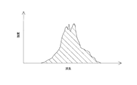
- the spectrum (wavelength-spectrum intensity graph) is calculated so that the area becomes 1 for the light emitted from each laser light source 21.
- the spectrum shown in FIG. 5 is a spectrum of the laser semiconductor 211 composed of a plurality of (for example, 24) light emitting portions (emitters), and thus has an uneven shape.
- the two lights by calculating the area of the overlapping portion (shaded portion in FIG. 6) of the spectrum of the two lights, it is determined whether the two lights have the same wavelength or different wavelengths.
- different wavelengths are used when the overlapping area is 0.24 or less.
- the wavelengths are different when the area of the overlapping portion is 0.07 or less. More preferably, the wavelengths are different when the area of the overlapping portion is 0.07 or less and the peak wavelength is more than the average value of the full width at half maximum of the spectrum.
- the area of an overlapping part is larger than 0.24, it is set as an equal wavelength.
- the incident angles are different.
- the incident angles are different in the two lights.
- the difference in the incident angle of the optical axis with respect to the incident surface 23a of the light guide 23 is 5 ° or more, “the incident angles are different”.
- the difference in the incident angle of the optical axis with respect to the incident surface 23a of the light guide 23 is 8 ° or more, “the incident angles are different”.
- the incident angles are equal in the two lights.
- FIGS. 7 and 8 show the incident position of each light with respect to the incident surface 22a of the optical system 22, as shown in FIG.
- the light emitted from the laser light source device 2 is incident on the rod integrator, the end surface image of the rod integrator is projected on the screen 100 by about 100 times, and the screen 100 is photographed with a CCD camera.
- the speckle contrast was measured from the image projected on the screen 100.
- the speckle contrast is obtained by dividing the standard deviation of the light intensity at each pixel of the CCD by the average value of the light intensity at each pixel. The larger the speckle contrast is, the higher the intensity of the light intensity (speckle noise). .
- the speckle contrast is 9.5%.
- the optical axes A41 and A42 of the lights L41 and L42 having the same wavelength are located at different distances from the center on the incident surface 22a of the optical system 22, that is, the incident surface 23a of the light guide 23.
- the speckle contrast is 8.2%.
- the same two lights L51 and L52 having a wavelength of 530 nm and one light L53 having a wavelength of 534 nm are present is verified.
- the optical axes A51 to 53 of the lights L51 to 53 are located at different distances from the center on the incident surface 22a of the optical system 22, that is, the optical axes A51 to A53 with respect to the incident surface 23a of the light guide 23.
- the speckle contrast is 7.5%.
- the optical axes A51 and 53 of the light beams L51 and L53 having different wavelengths are located at the same distance from the center on the incident surface 22a of the optical system 22, that is, on the incident surface 23a of the light guide 23.
- the incident angles of the optical axes A51 and A53 of the light beams L51 and L53 having different wavelengths are equal, the speckle contrast is 7.7%.
- the light emitted from the plurality of laser light sources 21 is incident on the optical system 22, and the light emitted from the optical system 22 is The light enters the incident surface 23 a of the light guide 23. And in the light radiate
- the image projection device 1 and the laser light source device 2 according to the present embodiment, three laser light sources 21 that emit light of the same wavelength are provided.
- the optical axes A11 to A13 (A21 to A23, A31 to A33) with respect to the incident surface 23a of the light guide 23 are used.
- the incident angles ⁇ 1 to ⁇ 3 are all different. Thereby, speckle noise can be more effectively reduced.
- the optical axes L11, L21, L31 (L12, L22, L32) (L13, L23, L33) with respect to the incident surface 23a of the light guide 23 are used.
- Three laser light sources 21 that emit light having the same incident angle ⁇ 1 ( ⁇ 2) ( ⁇ 3) are provided. These laser light sources 21 emit light having different wavelengths. As a result, a sufficient amount of light can be incident on the light guide 23 and the occurrence of speckle noise can be suppressed.
- this invention is not limited to the structure of above-described embodiment, and is not limited to the above-mentioned effect.
- the present invention can be variously modified without departing from the gist of the present invention.
- configurations, methods, and the like according to various modifications described below may be arbitrarily selected and employed in the configurations, methods, and the like according to the above-described embodiments.
- the image projection apparatus 1 according to the above embodiment is configured to include three laser light source devices 2R, 2G, and 2B.
- the image projector 1 according to the present invention is not limited to such a configuration.
- the image projection apparatus 1 according to the present invention may have a configuration including one laser light source device 2, a configuration including two laser light source devices 2, and a configuration including four or more laser light source devices 2. .
- the plurality of laser light sources 21 emit light having a plurality of wavelengths.
- the laser light source device 2 according to the present invention is not limited to such a configuration.
- the plurality of laser light sources 21 may emit light L61 to L66 having the same wavelength as shown in FIG.
- FIG. 9 shows the incident positions of the lights L61 to L66 with respect to the incident surface 22a of the optical system 22, as shown in FIG. FIG. 9 shows that six lights L61 to L66 having the same wavelength are incident on the incident surface 22a of the optical system 22.
- the laser light source device 2 according to the above-described embodiment has a configuration in which the incident angle of the optical axis with respect to the incident surface 23a of the light guide 23 is different for light having the same wavelength.
- the laser light source device 2 according to the present invention is not limited to such a configuration.
- the laser light source device 2 according to the present invention guides a part of the light L72, L73 (L75, L76) among the light L72, L73, L75, L76 having the same wavelength.
- the structure that the incident angle of the optical axis with respect to the incident surface 23a of the body 23 is equal may be sufficient.
- FIG. 10 shows the incident positions of the lights L71 to L76 with respect to the incident surface 22a of the optical system 22, as shown in FIG. In FIG. 10, the two lights L71 and L74 having the first wavelength and the four lights L72, L73, L75, and L76 having the second wavelength are incident on the incident surface 22a of the optical system 22. Show.
- the laser light source device 2 according to the above-described embodiment has a configuration in which light having the same incident angle of the optical axis with respect to the incident surface 23a of the light guide 23 is light having different wavelengths.
- the laser light source device 2 according to the present invention is not limited to such a configuration.
- the laser light source device 2 according to the present invention includes some light L71 and L72 (of the light L71 to L73 having the same incident angle of the optical axis with respect to the incident surface 23a of the light guide 23 ( L73) may be configured such that the wavelengths are different.
- the laser light source device 2 according to the above embodiment is configured to be used in the image projection device 1.
- the laser light source device 2 according to the present invention is not limited to such a configuration.
- the laser light source apparatus 2 according to the present invention may be configured to be used in an exposure apparatus that performs exposure using laser light.
- the laser light source device 2 is configured to include the optical system 22.
- the laser light source device according to the present invention is not limited to such a configuration.
- the laser light source apparatus according to the present invention may have a configuration in which the optical system 22 is not provided and the laser light emitted from the laser light source 21 is directly incident on the incident surface 23 a of the light guide 23.
- the laser light source device 2 is configured to include the light guide 23.
- the laser light source device according to the present invention is not limited to such a configuration.
- the laser light source device according to the present invention may be configured not to include the light guide 23 itself but to include a connection portion that detachably connects the light guide 23.
- SYMBOLS 1 ... Image projector, 2, 2R, 2G, 2B ... Laser light source device, 3 ... Spatial modulation element, 4 ... Color synthetic
Landscapes
- Physics & Mathematics (AREA)
- General Physics & Mathematics (AREA)
- Optics & Photonics (AREA)
- Engineering & Computer Science (AREA)
- Multimedia (AREA)
- Signal Processing (AREA)
- Projection Apparatus (AREA)
- Transforming Electric Information Into Light Information (AREA)
- Non-Portable Lighting Devices Or Systems Thereof (AREA)
Priority Applications (2)
| Application Number | Priority Date | Filing Date | Title |
|---|---|---|---|
| CN201480048850.7A CN105518517B (zh) | 2013-09-05 | 2014-08-21 | 激光光源装置及图像投影装置 |
| US14/916,010 US20160223894A1 (en) | 2013-09-05 | 2014-08-21 | Laser light source device and image projection device |
Applications Claiming Priority (2)
| Application Number | Priority Date | Filing Date | Title |
|---|---|---|---|
| JP2013183755A JP6008810B2 (ja) | 2013-09-05 | 2013-09-05 | レーザ光源装置 |
| JP2013-183755 | 2013-09-05 |
Publications (1)
| Publication Number | Publication Date |
|---|---|
| WO2015033792A1 true WO2015033792A1 (ja) | 2015-03-12 |
Family
ID=52628270
Family Applications (1)
| Application Number | Title | Priority Date | Filing Date |
|---|---|---|---|
| PCT/JP2014/071893 Ceased WO2015033792A1 (ja) | 2013-09-05 | 2014-08-21 | レーザ光源装置及び画像投影装置 |
Country Status (4)
| Country | Link |
|---|---|
| US (1) | US20160223894A1 (enExample) |
| JP (1) | JP6008810B2 (enExample) |
| CN (1) | CN105518517B (enExample) |
| WO (1) | WO2015033792A1 (enExample) |
Families Citing this family (7)
| Publication number | Priority date | Publication date | Assignee | Title |
|---|---|---|---|---|
| JP2016161846A (ja) * | 2015-03-04 | 2016-09-05 | ウシオ電機株式会社 | 光源装置及び画像投影装置 |
| US20160327721A1 (en) * | 2015-05-04 | 2016-11-10 | Corning Incorporated | Optical fiber lighting device and method |
| JP6866565B2 (ja) * | 2016-01-20 | 2021-04-28 | ウシオ電機株式会社 | 光源装置 |
| JP6763180B2 (ja) * | 2016-04-01 | 2020-09-30 | ウシオ電機株式会社 | 光源装置 |
| JP7036436B2 (ja) * | 2016-05-23 | 2022-03-15 | アダマンド並木精密宝石株式会社 | 光伝搬装置、その光伝搬装置を用いた光表示装置及び照明装置 |
| JP6810650B2 (ja) * | 2017-04-17 | 2021-01-06 | 日本電信電話株式会社 | 映像投影装置 |
| CN111352287A (zh) * | 2018-12-24 | 2020-06-30 | 深圳光峰科技股份有限公司 | 光源系统及投影设备 |
Citations (8)
| Publication number | Priority date | Publication date | Assignee | Title |
|---|---|---|---|---|
| JP2005300712A (ja) * | 2004-04-08 | 2005-10-27 | Nikon Corp | 投射型表示装置 |
| JP2008096777A (ja) * | 2006-10-13 | 2008-04-24 | Mitsubishi Electric Corp | レーザ光源装置及び映像表示装置 |
| JP2008299063A (ja) * | 2007-05-31 | 2008-12-11 | Sanyo Electric Co Ltd | 投写型映像表示装置 |
| JP2011242537A (ja) * | 2010-05-17 | 2011-12-01 | Mitsubishi Electric Corp | レーザ光源装置 |
| JP2012048832A (ja) * | 2010-08-24 | 2012-03-08 | Seiko Epson Corp | 光源装置、及びプロジェクター |
| JP2012128214A (ja) * | 2010-12-16 | 2012-07-05 | Ushio Inc | レーザ光源装置 |
| JP2013015762A (ja) * | 2011-07-06 | 2013-01-24 | Sony Corp | 照明光学系および画像表示装置 |
| JP2013030453A (ja) * | 2011-06-24 | 2013-02-07 | Sharp Corp | 投光装置、投光ユニットおよび集光部材 |
Family Cites Families (13)
| Publication number | Priority date | Publication date | Assignee | Title |
|---|---|---|---|---|
| JPH10304152A (ja) * | 1997-04-23 | 1998-11-13 | Minolta Co Ltd | レーザダイオードアレイ光源及び光ビーム走査光学装置 |
| AU2001271955A1 (en) * | 2000-07-10 | 2002-01-21 | Corporation For Laser Optics Research | Systems and methods for speckle reduction through bandwidth enhancement |
| US7016018B2 (en) * | 2003-06-04 | 2006-03-21 | Fuji Photo Film Co., Ltd. | Exposure device |
| WO2007013221A1 (ja) * | 2005-07-28 | 2007-02-01 | Matsushita Electric Industrial Co., Ltd. | レーザ画像表示装置、ならびに、それに用いる光インテグレータおよびレーザ光源パッケージ |
| JP4441918B2 (ja) * | 2006-08-31 | 2010-03-31 | セイコーエプソン株式会社 | 光源装置及び画像表示装置 |
| WO2009028438A1 (ja) * | 2007-08-29 | 2009-03-05 | Sharp Kabushiki Kaisha | 画像表示装置 |
| JP4381460B2 (ja) * | 2007-09-04 | 2009-12-09 | 三菱電機株式会社 | レーザ光合成装置 |
| US20090153752A1 (en) * | 2007-12-14 | 2009-06-18 | Silverstein Barry D | Projector using independent multiple wavelength light sources |
| JP5391662B2 (ja) * | 2008-11-21 | 2014-01-15 | ソニー株式会社 | 立体画像表示装置、偏光分離合成装置、立体画像表示方法 |
| EP2697682B1 (en) * | 2011-04-12 | 2019-11-13 | Barco NV | Laser projector with reduced speckle |
| US9228710B2 (en) * | 2011-06-13 | 2016-01-05 | Sharp Kabushiki Kaisha | Light projection apparatus, light condensing unit, and light emitting apparatus |
| JP5892769B2 (ja) * | 2011-11-07 | 2016-03-23 | 三菱電機株式会社 | 投写型表示装置及び画像表示方法 |
| JP5295468B1 (ja) * | 2012-02-02 | 2013-09-18 | 三菱電機株式会社 | 集光光学系および投写型画像表示装置 |
-
2013
- 2013-09-05 JP JP2013183755A patent/JP6008810B2/ja not_active Expired - Fee Related
-
2014
- 2014-08-21 WO PCT/JP2014/071893 patent/WO2015033792A1/ja not_active Ceased
- 2014-08-21 US US14/916,010 patent/US20160223894A1/en not_active Abandoned
- 2014-08-21 CN CN201480048850.7A patent/CN105518517B/zh not_active Expired - Fee Related
Patent Citations (8)
| Publication number | Priority date | Publication date | Assignee | Title |
|---|---|---|---|---|
| JP2005300712A (ja) * | 2004-04-08 | 2005-10-27 | Nikon Corp | 投射型表示装置 |
| JP2008096777A (ja) * | 2006-10-13 | 2008-04-24 | Mitsubishi Electric Corp | レーザ光源装置及び映像表示装置 |
| JP2008299063A (ja) * | 2007-05-31 | 2008-12-11 | Sanyo Electric Co Ltd | 投写型映像表示装置 |
| JP2011242537A (ja) * | 2010-05-17 | 2011-12-01 | Mitsubishi Electric Corp | レーザ光源装置 |
| JP2012048832A (ja) * | 2010-08-24 | 2012-03-08 | Seiko Epson Corp | 光源装置、及びプロジェクター |
| JP2012128214A (ja) * | 2010-12-16 | 2012-07-05 | Ushio Inc | レーザ光源装置 |
| JP2013030453A (ja) * | 2011-06-24 | 2013-02-07 | Sharp Corp | 投光装置、投光ユニットおよび集光部材 |
| JP2013015762A (ja) * | 2011-07-06 | 2013-01-24 | Sony Corp | 照明光学系および画像表示装置 |
Also Published As
| Publication number | Publication date |
|---|---|
| CN105518517B (zh) | 2018-12-07 |
| US20160223894A1 (en) | 2016-08-04 |
| JP2015052626A (ja) | 2015-03-19 |
| CN105518517A (zh) | 2016-04-20 |
| JP6008810B2 (ja) | 2016-10-19 |
Similar Documents
| Publication | Publication Date | Title |
|---|---|---|
| JP6008810B2 (ja) | レーザ光源装置 | |
| TWI531853B (zh) | 投影機 | |
| TWI574098B (zh) | 雷射投影光源 | |
| TW201316035A (zh) | 照明光學系統及影像顯示設備 | |
| TWI530750B (zh) | 投影裝置 | |
| CN104583864A (zh) | 照明光学系统、投影仪和投影仪系统 | |
| JP6009044B2 (ja) | レーザ光源装置 | |
| US9690106B2 (en) | Light homogenization device | |
| CN108700796B (zh) | 投射型显示装置 | |
| CN108292088B (zh) | 投射型显示装置和其设计方法 | |
| JP5804101B2 (ja) | レーザ光源装置及び画像投影装置 | |
| JP5804102B2 (ja) | レーザ光源装置及び画像投影装置 | |
| US10845581B2 (en) | Optical apparatus | |
| JP2017032964A (ja) | 光学系およびそれを用いた画像表示装置 | |
| WO2014199485A1 (ja) | 照明光学系、プロジェクターおよびプロジェクターシステム | |
| KR20110132872A (ko) | 프로젝션 시스템 | |
| JP2016118680A (ja) | 光源装置及び画像投影装置 | |
| JP5800049B1 (ja) | 光源装置及び画像投影装置 | |
| JP6215513B2 (ja) | 複数のコヒーレント光源からの光を合成する装置 | |
| JP2009031567A (ja) | 投写型表示装置および投写方法 | |
| WO2016140046A1 (ja) | 光源装置及び画像投影装置 | |
| JP2015162662A (ja) | レーザ光源装置及び画像投影装置 | |
| JP2016096109A (ja) | 光源装置 | |
| JP2014119655A (ja) | 画像表示装置 | |
| RU2006108387A (ru) | Проекционная система |
Legal Events
| Date | Code | Title | Description |
|---|---|---|---|
| 121 | Ep: the epo has been informed by wipo that ep was designated in this application |
Ref document number: 14842107 Country of ref document: EP Kind code of ref document: A1 |
|
| WWE | Wipo information: entry into national phase |
Ref document number: 14916010 Country of ref document: US |
|
| NENP | Non-entry into the national phase |
Ref country code: DE |
|
| 122 | Ep: pct application non-entry in european phase |
Ref document number: 14842107 Country of ref document: EP Kind code of ref document: A1 |