WO2015033528A1 - 弁装置 - Google Patents
弁装置 Download PDFInfo
- Publication number
- WO2015033528A1 WO2015033528A1 PCT/JP2014/004312 JP2014004312W WO2015033528A1 WO 2015033528 A1 WO2015033528 A1 WO 2015033528A1 JP 2014004312 W JP2014004312 W JP 2014004312W WO 2015033528 A1 WO2015033528 A1 WO 2015033528A1
- Authority
- WO
- WIPO (PCT)
- Prior art keywords
- valve body
- pilot
- passage
- main valve
- pressure chamber
- Prior art date
- Legal status (The legal status is an assumption and is not a legal conclusion. Google has not performed a legal analysis and makes no representation as to the accuracy of the status listed.)
- Ceased
Links
Images



Classifications
-
- F—MECHANICAL ENGINEERING; LIGHTING; HEATING; WEAPONS; BLASTING
- F16—ENGINEERING ELEMENTS AND UNITS; GENERAL MEASURES FOR PRODUCING AND MAINTAINING EFFECTIVE FUNCTIONING OF MACHINES OR INSTALLATIONS; THERMAL INSULATION IN GENERAL
- F16K—VALVES; TAPS; COCKS; ACTUATING-FLOATS; DEVICES FOR VENTING OR AERATING
- F16K39/00—Devices for relieving the pressure on the sealing faces
- F16K39/02—Devices for relieving the pressure on the sealing faces for lift valves
- F16K39/024—Devices for relieving the pressure on the sealing faces for lift valves using an auxiliary valve on the main valve
-
- F—MECHANICAL ENGINEERING; LIGHTING; HEATING; WEAPONS; BLASTING
- F16—ENGINEERING ELEMENTS AND UNITS; GENERAL MEASURES FOR PRODUCING AND MAINTAINING EFFECTIVE FUNCTIONING OF MACHINES OR INSTALLATIONS; THERMAL INSULATION IN GENERAL
- F16K—VALVES; TAPS; COCKS; ACTUATING-FLOATS; DEVICES FOR VENTING OR AERATING
- F16K31/00—Actuating devices; Operating means; Releasing devices
- F16K31/02—Actuating devices; Operating means; Releasing devices electric; magnetic
- F16K31/06—Actuating devices; Operating means; Releasing devices electric; magnetic using a magnet, e.g. diaphragm valves, cutting off by means of a liquid
- F16K31/0644—One-way valve
- F16K31/0655—Lift valves
-
- F—MECHANICAL ENGINEERING; LIGHTING; HEATING; WEAPONS; BLASTING
- F16—ENGINEERING ELEMENTS AND UNITS; GENERAL MEASURES FOR PRODUCING AND MAINTAINING EFFECTIVE FUNCTIONING OF MACHINES OR INSTALLATIONS; THERMAL INSULATION IN GENERAL
- F16K—VALVES; TAPS; COCKS; ACTUATING-FLOATS; DEVICES FOR VENTING OR AERATING
- F16K31/00—Actuating devices; Operating means; Releasing devices
- F16K31/02—Actuating devices; Operating means; Releasing devices electric; magnetic
- F16K31/06—Actuating devices; Operating means; Releasing devices electric; magnetic using a magnet, e.g. diaphragm valves, cutting off by means of a liquid
- F16K31/0644—One-way valve
- F16K31/0655—Lift valves
- F16K31/0665—Lift valves with valve member being at least partially ball-shaped
-
- F—MECHANICAL ENGINEERING; LIGHTING; HEATING; WEAPONS; BLASTING
- F16—ENGINEERING ELEMENTS AND UNITS; GENERAL MEASURES FOR PRODUCING AND MAINTAINING EFFECTIVE FUNCTIONING OF MACHINES OR INSTALLATIONS; THERMAL INSULATION IN GENERAL
- F16K—VALVES; TAPS; COCKS; ACTUATING-FLOATS; DEVICES FOR VENTING OR AERATING
- F16K31/00—Actuating devices; Operating means; Releasing devices
- F16K31/12—Actuating devices; Operating means; Releasing devices actuated by fluid
- F16K31/36—Actuating devices; Operating means; Releasing devices actuated by fluid in which fluid from the circuit is constantly supplied to the fluid motor
- F16K31/40—Actuating devices; Operating means; Releasing devices actuated by fluid in which fluid from the circuit is constantly supplied to the fluid motor with electrically-actuated member in the discharge of the motor
- F16K31/406—Actuating devices; Operating means; Releasing devices actuated by fluid in which fluid from the circuit is constantly supplied to the fluid motor with electrically-actuated member in the discharge of the motor acting on a piston
- F16K31/408—Actuating devices; Operating means; Releasing devices actuated by fluid in which fluid from the circuit is constantly supplied to the fluid motor with electrically-actuated member in the discharge of the motor acting on a piston the discharge being effected through the piston and being blockable by an electrically-actuated member making contact with the piston
Definitions
- the present invention relates to a valve device used as, for example, a pneumatic control device or a gas tank plug.
- Patent Document 1 discloses a valve device in which a main valve body and a pilot valve body are arranged coaxially.
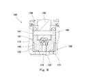
- FIG. 8 shows a part of the valve device 100 disclosed in Patent Document 1.
- a primary passage 121, a pressure chamber 122, and a secondary passage 123 constituting the main passage 120 are formed in the housing 110, and the secondary passage 123 is opened and closed by the main valve body 140.
- a pilot chamber 130 is formed on the opposite side of the main valve body 140 from the pressure chamber 122, and the pilot chamber 130 is pressurized through a first pilot passage 131 that is a gap between the main valve body 140 and the housing 110. It communicates with the chamber 122.
- a second pilot passage 132 is formed in the main valve body 140, and the second pilot passage 132 is opened and closed by the pilot valve body 150.
- the pilot valve body 150 is driven by a solenoid (not shown).
- the main valve body 140 and the pilot valve body 150 are connected by a pin 160.
- the pin 160 is fitted into the lateral hole provided in the pilot valve body 150 without a gap, a gap is formed between the pin 160 and the support hole 141 provided in the main valve body 140.
- the valve body 150 can be separated from the main valve body 140 by the gap.
- the pilot valve body 150 is pressed against the main valve body 140 by a spring (not shown).
- the solenoid (not shown) is energized, first, the pilot valve body 150 is separated from the main valve body 140 by the gap between the support hole 141 and the pin 160. Thereby, the second pilot passage 132 is opened. Thereafter, when the differential pressure between the pilot chamber 130 and the secondary passage 123 is reduced, and the suction force of the pilot valve body 150 by the solenoid overcomes the biasing force of the spring that biases the pilot valve body 150 and the pressure of the pilot chamber 130, The main valve body 140 is pulled up. As a result, the secondary passage 123 is opened.
- an object of the present invention is to provide a valve device that can reduce the size of a drive mechanism for a pilot valve body and is excellent in responsiveness.
- a valve device of the present invention includes a housing having a valve body space between the primary passage and the secondary passage, in which a primary passage and a secondary passage constituting a main passage are formed.
- a main valve body for opening and closing the secondary passage which is disposed in the housing so as to partition the valve body space into a first pressure chamber and a second pressure chamber communicating with the primary passage and the secondary passage;
- a first pilot passage having a first throttle, one end communicating directly or indirectly with the primary passage and the other end communicating with the second pressure chamber, and the second pressure chamber to the secondary passage.
- a second pilot passage having a second throttle formed in the main valve body, a pilot valve body disposed in the second pressure chamber for opening and closing the second pilot passage, and the pilot valve body Biasing member pressed against the main valve body
- a drive mechanism that drives the pilot valve body in a direction to open the second pilot passage against the urging force of the urging member when energized; and a pin that connects the main valve body and the pilot valve body.
- the second pilot passage is opened by a body and the pressure in the second pressure chamber is lower than the pressure in the first pressure chamber, the second pressure chamber and the second pressure chamber are caused by the differential pressure between the second pressure chamber and the second pressure chamber. It is comprised so that it may drive in the direction which opens a next channel
- the valve device since the main valve body is driven in the opening direction by the differential pressure between the first pressure chamber and the second pressure chamber, if the second pilot passage is opened by the pilot valve body, The main valve element opens instantly due to the pressure drop. Therefore, the valve device has excellent responsiveness.
- the drive mechanism for the pilot valve body only needs to have the power necessary to drive the pilot valve body by the gap between the pin and the main valve body or the pilot valve body. be able to.
- the second pilot passage having the second throttle is formed in the main valve body, the valve seat area of the pilot valve body is reduced, and the pilot valve body can be opened with less driving power. . Further, since the main valve body and the pilot valve body are connected by the pin, the state where the main valve body opens the secondary passage can be maintained by using the power of the drive mechanism.
- the drive mechanism is a solenoid including a fixed magnetic pole that attracts the pilot valve body, and the housing is provided with a stopper for the main valve body, and the second pilot passage and the secondary passage are closed.
- the distance from the pilot valve body to the fixed magnetic pole may be greater than the distance from the main valve body to the stopper and the sum of the gaps. According to this configuration, the main valve body can be pressed against the stopper by the suction force of the solenoid while the solenoid is energized.
- the first pilot passage may be formed in the housing or the main valve body. According to this configuration, the first aperture can be formed with high accuracy by machining.
- the housing has a sliding chamber for slidably holding the main valve body, and the first pilot passage is a gap between the main valve body and the sliding chamber, and extends over the entire length. And function as the first diaphragm. According to this configuration, the first pilot passage and the first throttle can be made simple and inexpensive.
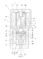
- (First embodiment) 1 and 2 show a valve device 1A according to a first embodiment of the present invention.
- the valve device 1A is used as a pneumatic control device, a gas tank plug, or the like.
- the fluid targeted by the valve device 1A is, for example, high-pressure gas.
- the valve device 1A of the present embodiment is a solenoid valve.
- the valve device 1 ⁇ / b> A includes a housing 2, a main valve body 4 and a pilot valve body 5 disposed in the housing 2, and a solenoid (drive mechanism) 7 that drives the pilot valve body 5.
- a solenoid (drive mechanism) 7 that drives the pilot valve body 5.
- the valve device 1A is not limited to a solenoid valve that employs the solenoid 7 as a drive mechanism.
- a piezoelectric actuator may be used as the drive mechanism.
- the piezoelectric actuator includes a piezoelectric element (for example, a piezo element) and generates a driving force according to an applied voltage.
- a force motor may be used as the drive mechanism. In the force motor, a movable coil is inserted into a cylindrical permanent magnet, and when a current is passed through the movable coil, an exciting force corresponding to the current is generated, and the movable coil is moved by this exciting force. .
- the main valve body 4 and the pilot valve body 5 are both rod-shaped members having a circular cross section, and their central axes are located on the same straight line. In other words, the main valve body 4 and the pilot valve body 5 are arranged coaxially.
- the direction in which the main valve body 4 and the pilot valve body 5 are aligned is the vertical direction (the pilot valve body 5 side is upward, the main valve body is The 4th side is called the lower side.
- the direction in which the main valve body 4 and the pilot valve body 5 are arranged may be a horizontal direction or an oblique direction.
- the housing 2 includes a first body 21 in which a primary passage 31 and a secondary passage 33 constituting the main passage 3 are formed, and a second body 22 in which a solenoid 7 is incorporated.
- the housing 2 has a valve body space 20 between the primary passage 31 and the secondary passage 33.
- the valve body space 20 extends across the first main body 21 and the second main body 22.
- the first main body 21 is formed with a cylindrical first sliding chamber 20a that holds the main valve body 4 so as to be slidable in the vertical direction, and the second main body 22 has a pilot valve body.
- a cylindrical second sliding chamber 20b is formed to hold 5 in a slidable manner in the vertical direction.
- the first main body 21 is provided with a stopper 23 that protrudes radially inward between the first sliding chamber 20a and the second sliding chamber 20b and stops the main valve body 4 that moves upward.
- the valve body space 20 described above is a continuous space defined by the first sliding chamber 20a, the stopper 23, and the second sliding chamber 20b.
- One end (upstream end) of the primary passage 31 is open to the side surface of the first main body 21, and the other end (downstream end) is open to the peripheral surface of the first sliding chamber 20a.
- one end (upstream end) of the secondary passage 33 opens on the bottom surface of the first sliding chamber 20 a, and the other end (downstream end) opens on the lower surface of the first main body 21.
- a first valve seat 25 for the main valve body 4 is formed around the upstream end of the secondary passage 33 on the bottom surface of the first sliding chamber 20a.
- the main valve body 4 is arranged in the housing 2 so as to partition the valve body space 20 into a first pressure chamber 32 and a second pressure chamber 24 communicating with the primary passage 31 and the secondary passage 33.
- the first pressure chamber 32 constitutes the main passage 3 together with the primary passage 31 and the secondary passage 33.
- the main valve body 4 includes a shaft portion 41 having a diameter smaller than the diameter of the peripheral surface of the first sliding chamber 20a and a first sliding chamber 20a extending upward from a peripheral portion on the upper side of the shaft portion 41. And a cylindrical portion 42 having an outer diameter substantially equal to the diameter of the peripheral surface.
- the cylindrical portion 42 is a portion that is slidably held in the first sliding chamber 20a. That is, the first pressure chamber 32 is defined between a portion of the peripheral surface of the first sliding chamber 20 a that is lower than the cylindrical portion 42 and the outer peripheral surface of the shaft portion 41.
- the second pressure chamber 24 is a space facing the upper surface of the shaft portion 41 and the inner peripheral surface of the cylindrical portion 42, a region above the main valve body 4 in the first sliding chamber 20 a, and the stopper 23. It is comprised by the inside and the 2nd sliding chamber 20b.
- the tubular portion 42 has a seal member (not shown) for isolating the first pressure chamber 32 and the second pressure chamber 24 between the peripheral surface of the first sliding chamber 20a and the main valve body 4. It may be attached.
- the main valve body 4 moves between a closed position where the shaft portion 41 is seated on the first valve seat 25 and an open position where the tubular portion 42 abuts against the stopper 23 to open and close the secondary passage 33.
- the secondary passage 33 is closed and the first pressure chamber 32 is isolated from the secondary passage 33, and when the shaft portion 41 is separated from the first valve seat 25, the secondary passage 33 is closed.
- the passage 33 is opened and the first pressure chamber 32 is connected to the secondary passage 33.
- a first pilot passage 61 is formed in the first main body 21 of the housing 2. One end (upstream end) of the first pilot passage 61 communicates directly with the primary passage 31, and the other end (downstream end) of the first pilot passage 61 communicates with the second pressure chamber 24.
- the first pilot passage 61 is provided with a first throttle 62 in the middle.
- a second pilot passage 63 is formed in the main valve body 4 so as to reach from the second pressure chamber 24 to the secondary passage 33.
- the second pilot passage 63 is disposed on the central axis of the main valve body 4, and one end (upstream end) of the second pilot passage 63 opens on the upper surface of the shaft portion 41, and the other end (downstream end) is the shaft portion. 41 is open to the tip surface.
- the second pilot passage 63 is provided with a second throttle 64 at the end on the second pressure chamber 24 side. The second pilot passage 63 is opened and closed by the pilot valve body 5.
- the pilot valve body 5 is disposed in the second pressure chamber 24.
- a biasing member 55 that presses the pilot valve body 5 against the main valve body 4 is disposed in the second pressure chamber 24.
- the first biasing member 55 is, for example, a compression coil spring.
- a vertical hole 53 on the central axis and a horizontal hole 54 that intersects with the lower end of the vertical hole 53 are formed in order to avoid the second pressure chamber 24 being vertically divided by the pilot valve body 5.
- a horizontal hole 54 that intersects with the lower end of the vertical hole 53 are formed in order to avoid the second pressure chamber 24 being vertically divided by the pilot valve body 5.
- pilot valve body 5 is inserted into the main body 51 that is slidably held in the second sliding chamber 20 b and the cylindrical portion 42 of the main valve body 4 that protrudes downward from the main body 51. And a shaft portion 52.
- a second valve seat 45 for the pilot valve body 5 is formed around the upstream end of the second pilot passage 63 on the upper surface of the shaft portion 41 of the main valve body 4.
- the second pilot passage 63 is closed, the second pressure chamber 24 is isolated from the second pilot passage 63, and when the shaft portion 52 is separated from the second valve seat 45, The second pilot passage 63 is opened and the second pressure chamber 24 is connected to the second pilot passage 63.
- the inner peripheral surface of the tubular portion 42 of the main valve body 4 and the shaft portion 52 of the pilot valve body 5. Through the gap between the outer peripheral surface of the main valve body 4 and the top surface of the shaft portion 41 of the main valve body 4 and the tip surface of the shaft portion 52 of the pilot valve body 5. Led.
- the solenoid 7 described above drives the pilot valve body 5 in a direction to open the second pilot passage 63 against the urging force of the urging member 55 by energization. That is, the pilot valve body 5 also functions as a movable iron core that is driven by the solenoid 7.
- the solenoid 7 includes a coil 71 wound around the second sliding chamber 20 b and a fixed magnetic pole 72 that is disposed above the pilot valve body 5 and attracts the pilot valve body 5.
- the fixed magnetic pole 72 is also a part of the second main body 22 of the housing 2.
- the shaft portion 52 of the pilot valve body 5 and the cylindrical portion 42 of the main valve body 4 are connected by a pin 8 extending in the horizontal direction perpendicular to the vertical direction.
- the shaft portion 52 of the pilot valve body 5 is formed with a lateral hole 56 that is inserted into the pin 8
- the cylindrical portion 42 of the main valve body 4 is formed with a support hole 43 that supports both ends of the pin 8.
- the support hole 43 is fitted to the pin 8 without a gap, and a gap is provided between the pin 8 and the lateral hole 56 below the pin 8 in a state where the pilot valve body 5 is in contact with the main valve body 4. e1 is formed.
- the horizontal hole 56 may be a circular hole having a diameter larger than that of the pin 8 or may be a long hole extending in the vertical direction with the same width as the diameter of the pin 8.
- the solenoid 7 sets the secondary pressure as the pressure of the secondary passage 33 to P2, the area of the second valve seat 45 to Ap, and the biasing force of the biasing member 55 to Fs.
- the suction force Fc is larger than Fs + Ap (P1-P2).
- the main valve body 4 When the second pilot passage 63 is opened by the pilot valve body 5 and the pressure in the second pressure chamber 24 is lower than the pressure in the first pressure chamber 32, the main valve body 4 is connected to the first pressure chamber 32 and the second pressure chamber 32. It is configured to be driven in a direction to open the secondary passage 33 by the differential pressure in the pressure chamber 24.
- the cross-sectional area of the first sliding chamber 20a is A1 and the area of the first valve seat 25 is Am
- the first diaphragm 62 and the second diaphragm 64 and the areas A1 and Am are set so as to satisfy the above.
- valve device 1A Next, the operation of the valve device 1A will be described. First, as shown in FIG. 1, the main valve body 4 will be described from a state where it is located at the closed position.
- the pilot valve body 5 When the solenoid 7 is not energized, the pilot valve body 5 is pressed against the main valve body 4 by the biasing member 55, and the second pilot passage 63 is closed. That is, the pressure in the second pilot passage 63 is equal to the secondary pressure P2, and the pressure in the first pilot passage 61 and the second pressure chamber 24 is equal to the primary pressure P1. For this reason, the shaft portion 52 of the pilot valve body 5 is caused by the pressing force (Ap (P1-P2)) corresponding to the biasing force Fs of the biasing member 55 and the differential pressure between the second pressure chamber 24 and the second pilot passage 63. It is pressed against the second valve seat 45.
- the shaft portion 41 of the main valve body 4 has a first pressing force (Am (P1-P2)) corresponding to the biasing force Fs of the biasing member 55 and the differential pressure between the second pressure chamber 24 and the secondary passage 33. It is pressed against the valve seat 25.
- the solenoid 7 When the solenoid 7 is energized, first, the pilot valve body 5 is raised by the clearance e1 by the suction force Fc of the solenoid 7. As a result, the second pilot passage 63 is opened, and the fluid flows from the primary passage 31 to the secondary passage 33 through the first pilot passage 61, the second pressure chamber 24 and the second pilot passage 63. As a result, the pressure Pr in the second pressure chamber 24 decreases to a pressure between the primary pressure P1 and the secondary pressure P2, and the main valve body 4 rises due to the differential pressure between the first pressure chamber 32 and the second pressure chamber 24. . As a result, the secondary passage 33 is opened.
- the main valve body 4 rises until the main valve body 4 comes into contact with the stopper 23. As the main valve body 4 is raised, the pilot valve body 5 connected to the main valve body 4 by the pin 8 is also raised by the suction force Fc of the solenoid 7.
- the distance E from the pilot valve body 5 to the fixed magnetic pole 72 can be separated from the main valve body 4 when the second pilot passage 63 and the secondary passage 33 are closed. Is set larger than the sum of the gap e1 and the distance e2 from the main valve body 4 to the stopper 23 (E> e1 + e2). For this reason, even when the main valve body 4 abuts against the stopper 23, a gap is secured between the pilot valve body 5 and the fixed magnetic pole 72 as shown in FIG. In other words, the main valve body 4 can be pressed against the stopper 23 by the suction force Fc of the solenoid 7.
- the main valve body 4 is restrained to the open position even if the supply of fluid is stopped on the downstream side of the valve device 1A and the fluid no longer flows into the main passage 3. can do.
- the clearance e1 that enables the pilot valve body 5 to be separated from the main valve body 4 is much smaller than the distance e2 that is also the stroke of the main valve body 4.
- the main valve body 4 is driven in the opening direction by the differential pressure between the first pressure chamber 32 and the second pressure chamber 24.
- the pilot passage 63 is opened, the main valve body 4 is opened instantly due to a decrease in the pressure in the second pressure chamber 24. Therefore, the valve device 1A has excellent responsiveness.
- the solenoid 7 for the pilot valve body 5 only needs to have a suction force necessary to drive the pilot valve body 5 by the gap e1 between the pin 8 and the pilot valve body 5, so that the solenoid 7 can be reduced in size.
- the second pilot passage having the second throttle 64 is formed in the main valve body 4, the valve seat area of the pilot valve body 5 is reduced, and the pilot valve body 5 is opened with less driving power. Is possible. Further, since the main valve body 4 and the pilot valve body 5 are connected by the pin 8, the state where the main valve body 4 opens the secondary passage 33 can be maintained by using the suction force of the solenoid 7.
- the distance E from the pilot valve body 5 to the fixed magnetic pole 72 is a clearance e1 that allows the pilot valve body 5 to be separated from the main valve body 4 and a distance e2 from the main valve body 4 to the stopper 23. It was set larger than the sum (E> e1 + e2). However, even if E ⁇ e1 + e2 (including e2 ⁇ E or the case where there is no stopper 23), the pilot valve body 5 comes into contact with the fixed magnetic pole 72 by energizing the solenoid 7, and the pilot valve body 5 and the pin The main valve body 4 connected by 8 can maintain an open position.
- the position of the main valve body 4 may change by a slight gap between the pin 8 and the lateral hole 56.
- E> e1 + e2 the suction force Fc of the solenoid 7 can be applied to the main valve body 4 located at the open position. Thereby, the position fluctuation
- This modification can also be applied to second to fifth embodiments described later.
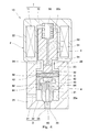
- valve apparatus 1B which concerns on 2nd Embodiment of this invention is demonstrated.
- the same components as those in the first embodiment are denoted by the same reference numerals, and redundant description is omitted.
- the lateral hole 56 provided in the pilot valve body 5 is fitted to the pin 8 without a gap, and the pilot valve body 5 is interposed between the support hole 43 provided in the main valve body 4 and the pin 8.
- a gap e1 that allows separation from the main valve body 4 is formed.
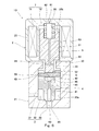
- a valve device 1C according to a third embodiment of the present invention will be described.
- a first pilot passage 61 having a first throttle 62 is formed in the main valve body 4, and the upstream end of the first pilot passage 61 communicates with the primary passage 31 indirectly through the first pressure chamber 32. is doing.
- a plurality of first pilot passages 61 may be formed around the shaft portion 41 of the main valve body 4.
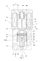
- a valve device 1D according to a fourth embodiment of the present invention will be described.
- a first pilot passage 61 having a first aperture 62 is formed in the fixed magnetic pole 72.
- This embodiment assumes that almost the entire valve device 1D is inserted into a gas tank (not shown). That is, the upstream end of the first pilot passage 61 indirectly communicates with the primary passage 31 through the internal space of the gas tank.
- the valve apparatus 1E which concerns on 5th Embodiment of this invention is demonstrated.
- the outer diameter of the cylindrical portion 42 of the main valve body 4 is set slightly smaller than those in the first to fourth embodiments, and the annular shape between the main valve body 4 and the first sliding chamber 20a is set.
- a first pilot passage 61 is formed by the gap.
- the first pilot passage 61 functions as the first throttle 62 over the entire length.
- the first pilot passage 61 and the first throttle 62 can be configured simply and inexpensively.
- the first throttle 62 can be formed with high accuracy by machining. it can.
- the gap between the main valve body 4 and the first sliding chamber 20a, which functions as the first pilot passage 61 and the first throttle 62, does not necessarily have to be an annular shape surrounding the main valve body 4, but the main valve body You may be comprised by the 1 or several groove
- the present invention is widely applicable to valve devices for various uses.
- Valve device 2 Housing 20 Valve body space 23 Stopper 24 Second pressure chamber 3 Main passage 31 Primary passage 32 First pressure chamber 33 Secondary passage 4 Main valve body 5 Pilot valve body 55 Energizing member 61 First pilot passage 62 1st aperture 63 2nd pilot passage 64 2nd aperture 7 Solenoid 8 pin e1 clearance
Landscapes
- Engineering & Computer Science (AREA)
- General Engineering & Computer Science (AREA)
- Mechanical Engineering (AREA)
- Fluid-Driven Valves (AREA)
- Magnetically Actuated Valves (AREA)
Abstract
Description
図1および図2に、本発明の第1実施形態に係る弁装置1Aを示す。弁装置1Aは、空圧用の制御機器やガスタンクの閉栓などとして用いられる。弁装置1Aが対象とする流体は、例えば高圧ガスである。
(P1-Pr)(A1-Am)>(Pr-P2)Am
を満たすように、第1絞り62および第2絞り64ならびに面積A1,Amが設定されている。
前記実施形態では、パイロット弁体5から固定磁極72までの距離Eは、パイロット弁体5の主弁体4からの離間を可能とする隙間e1と主弁体4からストッパー23までの距離e2の和よりも大きく設定されていた(E>e1+e2)。しかしながら、E≦e1+e2(e2≧E、又は、ストッパー23がない場合も含む)となっていても、ソレノイド7への通電によってパイロット弁体5が固定磁極72に当接し、パイロット弁体5とピン8によって連結された主弁体4は開位置を維持できる。ただし、その状態において、ピン8と横穴56の間の僅かな隙間分だけ、主弁体4が位置変動するおそれがある。これに対し、E>e1+e2となっていれば、開位置に位置した主弁体4にソレノイド7の吸引力Fcを作用させることができる。これにより、そのような主弁体4の位置変動を防止することができる。なお、本変形例は、後述する第2~第5実施形態においても適用可能である。
次に、図3を参照して、本発明の第2実施形態に係る弁装置1Bを説明する。なお、本実施形態および後述する第3~第5実施形態において、第1実施形態と同一構成要素には同一符号を付し、重複した説明は省略する。
次に、図4を参照して、本発明の第3実施形態に係る弁装置1Cを説明する。本実施形態では、第1絞り62を有する第1パイロット通路61が主弁体4に形成されており、第1パイロット通路61の上流端が第1圧力室32を通じて間接的に一次通路31と連通している。なお、図5に示すように、第1パイロット通路61は、主弁体4の軸部41の回りに複数形成されていてもよい。
次に、図6を参照して、本発明の第4実施形態に係る弁装置1Dを説明する。本実施形態では、第1絞り62を有する第1パイロット通路61が固定磁極72に形成されている。
次に、図7を参照して、本発明の第5実施形態に係る弁装置1Eを説明する。本実施形態では、主弁体4の筒状部42の外径が第1~第4実施形態よりも僅かに小さく設定されており、主弁体4と第1摺動室20aの間の環状隙間によって第1パイロット通路61が構成されている。そして、第1パイロット通路61は、全長に亘って第1絞り62として機能する。
2 ハウジング
20 弁体空間
23 ストッパー
24 第2圧力室
3 主通路
31 一次通路
32 第1圧力室
33 二次通路
4 主弁体
5 パイロット弁体
55 付勢部材
61 第1パイロット通路
62 第1絞り
63 第2パイロット通路
64 第2絞り
7 ソレノイド
8 ピン
e1 隙間
Claims (4)
- 主通路を構成する一次通路および二次通路が形成された、前記一次通路と前記二次通路の間に弁体空間を有するハウジングと、
前記弁体空間を前記一次通路および前記二次通路と連通する第1圧力室と第2圧力室とに仕切るように前記ハウジング内に配置された、前記二次通路を開閉する主弁体と、
一端が前記一次通路と直接的または間接的に連通し、他端が前記第2圧力室と連通する、第1絞りを有する第1パイロット通路と、
前記第2圧力室から前記二次通路へ至るように前記主弁体に形成された、第2絞りを有する第2パイロット通路と、
前記第2圧力室内に配置された、前記第2パイロット通路を開閉するパイロット弁体と、
前記パイロット弁体を前記主弁体に押し付ける付勢部材と、
通電により前記パイロット弁体を前記付勢部材の付勢力に抗して前記第2パイロット通路を開く方向に駆動する駆動機構と、
前記主弁体と前記パイロット弁体とを連結するピンであって、前記主弁体または前記パイロット弁体との間に前記パイロット弁体の前記主弁体からの離間を可能とする隙間が形成されたピンと、を備え、
前記主弁体が、前記パイロット弁体により前記第2パイロット通路が開かれて前記第2圧力室の圧力が前記第1圧力室の圧力よりも低下したときに、前記第1圧力室と前記第2圧力室の差圧によって前記二次通路を開く方向に駆動されるように構成されている、弁装置。 - 前記駆動機構は、前記パイロット弁体を吸引する固定磁極を含むソレノイドであり、
前記ハウジングには、前記主弁体用のストッパーが設けられており、
前記第2パイロット通路および前記二次通路が閉じられた状態において、前記パイロット弁体から前記固定磁極までの距離は、前記主弁体から前記ストッパーまでの距離と前記隙間の和よりも大きい、請求項1に記載の弁装置。 - 前記第1パイロット通路が前記ハウジングまたは前記主弁体に形成されている、請求項1または2に記載の弁装置。
- 前記ハウジングは、前記主弁体を摺動可能に保持する摺動室を有し、
前記第1パイロット通路は、前記主弁体と前記摺動室の間の隙間であり、全長に亘って前記第1絞りとして機能する、請求項1または2に記載の弁装置。
Priority Applications (3)
| Application Number | Priority Date | Filing Date | Title |
|---|---|---|---|
| US14/914,200 US20160208954A1 (en) | 2013-09-03 | 2014-08-21 | Valve device |
| DE112014004012.6T DE112014004012T5 (de) | 2013-09-03 | 2014-08-21 | Ventilvorrichtung |
| CA2920997A CA2920997A1 (en) | 2013-09-03 | 2014-08-21 | Valve device |
Applications Claiming Priority (2)
| Application Number | Priority Date | Filing Date | Title |
|---|---|---|---|
| JP2013-181910 | 2013-09-03 | ||
| JP2013181910A JP2015048916A (ja) | 2013-09-03 | 2013-09-03 | 弁装置 |
Publications (1)
| Publication Number | Publication Date |
|---|---|
| WO2015033528A1 true WO2015033528A1 (ja) | 2015-03-12 |
Family
ID=52628029
Family Applications (1)
| Application Number | Title | Priority Date | Filing Date |
|---|---|---|---|
| PCT/JP2014/004312 Ceased WO2015033528A1 (ja) | 2013-09-03 | 2014-08-21 | 弁装置 |
Country Status (5)
| Country | Link |
|---|---|
| US (1) | US20160208954A1 (ja) |
| JP (1) | JP2015048916A (ja) |
| CA (1) | CA2920997A1 (ja) |
| DE (1) | DE112014004012T5 (ja) |
| WO (1) | WO2015033528A1 (ja) |
Cited By (1)
| Publication number | Priority date | Publication date | Assignee | Title |
|---|---|---|---|---|
| WO2016136239A1 (ja) * | 2015-02-26 | 2016-09-01 | 川崎重工業株式会社 | 弁装置 |
Families Citing this family (21)
| Publication number | Priority date | Publication date | Assignee | Title |
|---|---|---|---|---|
| DE102015104154B4 (de) * | 2015-03-19 | 2022-11-24 | Beko Technologies Gmbh | Drucktaupunktgesteuerte Spülluftregeleinheit |
| DE102015005977A1 (de) * | 2015-05-08 | 2016-11-10 | Daimler Ag | Entnahmeventil |
| KR101821597B1 (ko) * | 2016-05-10 | 2018-01-26 | 영도산업 주식회사 | 유체 제어용 솔레노이드 밸브 |
| JP6504373B2 (ja) * | 2017-04-06 | 2019-04-24 | 株式会社清和モールド | エアバルブ |
| JP2020070900A (ja) * | 2018-11-01 | 2020-05-07 | 株式会社ニッキ | パイロット式電磁弁 |
| DE102019211730A1 (de) * | 2019-08-05 | 2021-02-11 | Robert Bosch Gmbh | Tankvorrichtung zur Speicherung eines gasförmigen Mediums |
| CN110594479B (zh) * | 2019-09-12 | 2024-04-05 | 江苏国富氢能技术装备股份有限公司 | 一种瓶口阀中的先导式电磁阀 |
| DE102020201364A1 (de) * | 2020-02-05 | 2021-08-05 | Robert Bosch Gesellschaft mit beschränkter Haftung | Tankvorrichtung zur Speicherung eines gasförmigen Mediums |
| WO2022030315A1 (ja) | 2020-08-04 | 2022-02-10 | イーグル工業株式会社 | 膨張弁 |
| WO2022030312A1 (ja) | 2020-08-04 | 2022-02-10 | イーグル工業株式会社 | 弁 |
| CN116134254B (zh) | 2020-08-04 | 2025-11-07 | 伊格尔工业股份有限公司 | 阀 |
| EP4194728A4 (en) * | 2020-08-04 | 2024-08-21 | Eagle Industry Co., Ltd. | VALVE |
| DE102020211860A1 (de) * | 2020-09-23 | 2022-03-24 | Robert Bosch Gesellschaft mit beschränkter Haftung | Tankvorrichtung mit einer Ventilvorrichtung |
| DE102020211865A1 (de) | 2020-09-23 | 2022-03-24 | Robert Bosch Gesellschaft mit beschränkter Haftung | Tankvorrichtung zur Speicherung eines gasförmigen Mediums mit einer Ventilvorrichtung |
| DE102020211862A1 (de) | 2020-09-23 | 2022-03-24 | Robert Bosch Gesellschaft mit beschränkter Haftung | Tankvorrichtung zur Speicherung eines gasförmigen Mediums mit einer Ventilvorrichtung |
| KR102879499B1 (ko) | 2020-09-28 | 2025-10-31 | 이구루코교 가부시기가이샤 | 밸브 |
| CN116457592A (zh) | 2020-10-01 | 2023-07-18 | 伊格尔工业股份有限公司 | 阀 |
| US11662039B2 (en) * | 2020-11-18 | 2023-05-30 | Tescom Corporation | High pressure direct pilot actuated valve |
| WO2022131053A1 (ja) | 2020-12-17 | 2022-06-23 | イーグル工業株式会社 | 弁 |
| CN117098943A (zh) | 2021-03-29 | 2023-11-21 | 伊格尔工业股份有限公司 | 阀 |
| JP2024145899A (ja) | 2023-03-31 | 2024-10-15 | 川崎重工業株式会社 | 弁装置 |
Citations (3)
| Publication number | Priority date | Publication date | Assignee | Title |
|---|---|---|---|---|
| US5048790A (en) * | 1990-07-18 | 1991-09-17 | Target Rock Corporation | Self-modulating control valve for high-pressure fluid flow |
| JPH0875029A (ja) * | 1994-09-07 | 1996-03-19 | Nichiden Kogyo Kk | 電磁弁 |
| JP2002071044A (ja) * | 2000-09-01 | 2002-03-08 | Aisan Ind Co Ltd | 双方向型パイロット式電磁流路開閉弁と双方向型配管 |
Family Cites Families (11)
| Publication number | Priority date | Publication date | Assignee | Title |
|---|---|---|---|---|
| US2575272A (en) * | 1947-07-17 | 1951-11-13 | Skinner Chuck Company | Rapid closure valve for high-flow rates at low-pressure drop |
| US3405906A (en) * | 1966-08-04 | 1968-10-15 | Itt | Solenoid pilot operated valve |
| US4650155A (en) * | 1983-11-04 | 1987-03-17 | Target Rock Corporation | Anti-cavitation valve assembly |
| US4699351A (en) * | 1984-07-11 | 1987-10-13 | Target Rock Corporation | Pressure responsive, pilot actuated, modulating valve |
| CH671080A5 (ja) * | 1986-10-01 | 1989-07-31 | Sulzer Ag | |
| US5188017A (en) * | 1991-06-18 | 1993-02-23 | The Consumers' Gas Company, Ltd. | Natural gas cylinder fitting and solenoid valve |
| JP2685732B2 (ja) * | 1995-03-29 | 1997-12-03 | シーケーディ株式会社 | パイロットキック式電磁弁 |
| JP3668605B2 (ja) * | 1997-12-17 | 2005-07-06 | シーケーディ株式会社 | パイロットキック式電磁弁 |
| JP5222700B2 (ja) * | 2008-11-27 | 2013-06-26 | 本田技研工業株式会社 | 電磁弁制御装置 |
| JP5498269B2 (ja) * | 2010-06-15 | 2014-05-21 | 川崎重工業株式会社 | 電磁式開閉弁 |
| JP5873451B2 (ja) * | 2013-02-26 | 2016-03-01 | 川崎重工業株式会社 | 弁装置 |
-
2013
- 2013-09-03 JP JP2013181910A patent/JP2015048916A/ja active Pending
-
2014
- 2014-08-21 DE DE112014004012.6T patent/DE112014004012T5/de not_active Ceased
- 2014-08-21 CA CA2920997A patent/CA2920997A1/en not_active Abandoned
- 2014-08-21 US US14/914,200 patent/US20160208954A1/en not_active Abandoned
- 2014-08-21 WO PCT/JP2014/004312 patent/WO2015033528A1/ja not_active Ceased
Patent Citations (3)
| Publication number | Priority date | Publication date | Assignee | Title |
|---|---|---|---|---|
| US5048790A (en) * | 1990-07-18 | 1991-09-17 | Target Rock Corporation | Self-modulating control valve for high-pressure fluid flow |
| JPH0875029A (ja) * | 1994-09-07 | 1996-03-19 | Nichiden Kogyo Kk | 電磁弁 |
| JP2002071044A (ja) * | 2000-09-01 | 2002-03-08 | Aisan Ind Co Ltd | 双方向型パイロット式電磁流路開閉弁と双方向型配管 |
Cited By (2)
| Publication number | Priority date | Publication date | Assignee | Title |
|---|---|---|---|---|
| WO2016136239A1 (ja) * | 2015-02-26 | 2016-09-01 | 川崎重工業株式会社 | 弁装置 |
| US10161360B2 (en) | 2015-02-26 | 2018-12-25 | Kawasaki Jukogyo Kabushiki Kaisha | Valve device |
Also Published As
| Publication number | Publication date |
|---|---|
| US20160208954A1 (en) | 2016-07-21 |
| CA2920997A1 (en) | 2015-03-12 |
| DE112014004012T5 (de) | 2016-05-25 |
| JP2015048916A (ja) | 2015-03-16 |
Similar Documents
| Publication | Publication Date | Title |
|---|---|---|
| WO2015033528A1 (ja) | 弁装置 | |
| JP6463647B2 (ja) | 弁装置 | |
| JP5873451B2 (ja) | 弁装置 | |
| KR102518258B1 (ko) | 가스용 솔레노이드 밸브 | |
| CN104121317B (zh) | 缓冲器 | |
| JP5894558B2 (ja) | 過流防止機能付き弁装置 | |
| JP4805320B2 (ja) | 電磁開閉弁 | |
| EP2492559A1 (en) | Solenoid valve | |
| JP7175208B2 (ja) | ガス用電磁弁 | |
| WO2015125404A1 (ja) | 弁装置 | |
| JP2016118222A (ja) | 電動弁 | |
| US20180355993A1 (en) | Hydraulic valve configuration for nh vbs with a nl solenoid | |
| CN112747162A (zh) | 一种燃气比例阀 | |
| CN107131165B (zh) | 电磁阀和压力流体控制设备 | |
| JP5722164B2 (ja) | 減圧装置 | |
| JP2012202491A (ja) | ソレノイドバルブ | |
| CN103688091B (zh) | 阀模块 | |
| CN114838139A (zh) | 一种双稳态无源自保持先导式电磁阀 | |
| CN221723409U (zh) | 一种先导式电磁阀 | |
| CN113302424B (zh) | 气体用电磁阀 | |
| JP5712092B2 (ja) | パイロット機能付き弁 | |
| WO2017131135A1 (ja) | 電磁切換弁 | |
| JP2013177976A (ja) | 減衰弁 | |
| JP2017015149A (ja) | 圧力流体制御装置 | |
| JP2008075661A (ja) | 内燃機関用流体回路および主弁 |
Legal Events
| Date | Code | Title | Description |
|---|---|---|---|
| 121 | Ep: the epo has been informed by wipo that ep was designated in this application |
Ref document number: 14841478 Country of ref document: EP Kind code of ref document: A1 |
|
| ENP | Entry into the national phase |
Ref document number: 2920997 Country of ref document: CA |
|
| WWE | Wipo information: entry into national phase |
Ref document number: 14914200 Country of ref document: US |
|
| WWE | Wipo information: entry into national phase |
Ref document number: 1120140040126 Country of ref document: DE Ref document number: 112014004012 Country of ref document: DE |
|
| 122 | Ep: pct application non-entry in european phase |
Ref document number: 14841478 Country of ref document: EP Kind code of ref document: A1 |