WO2015029618A1 - 炭化水素油の製造方法 - Google Patents
炭化水素油の製造方法 Download PDFInfo
- Publication number
- WO2015029618A1 WO2015029618A1 PCT/JP2014/068623 JP2014068623W WO2015029618A1 WO 2015029618 A1 WO2015029618 A1 WO 2015029618A1 JP 2014068623 W JP2014068623 W JP 2014068623W WO 2015029618 A1 WO2015029618 A1 WO 2015029618A1
- Authority
- WO
- WIPO (PCT)
- Prior art keywords
- catalyst
- oil
- mass
- reactivity
- desulfurization
- Prior art date
- Legal status (The legal status is an assumption and is not a legal conclusion. Google has not performed a legal analysis and makes no representation as to the accuracy of the status listed.)
- Ceased
Links
Images

Classifications
-
- C—CHEMISTRY; METALLURGY
- C10—PETROLEUM, GAS OR COKE INDUSTRIES; TECHNICAL GASES CONTAINING CARBON MONOXIDE; FUELS; LUBRICANTS; PEAT
- C10G—CRACKING HYDROCARBON OILS; PRODUCTION OF LIQUID HYDROCARBON MIXTURES, e.g. BY DESTRUCTIVE HYDROGENATION, OLIGOMERISATION, POLYMERISATION; RECOVERY OF HYDROCARBON OILS FROM OIL-SHALE, OIL-SAND, OR GASES; REFINING MIXTURES MAINLY CONSISTING OF HYDROCARBONS; REFORMING OF NAPHTHA; MINERAL WAXES
- C10G45/00—Refining of hydrocarbon oils using hydrogen or hydrogen-generating compounds
- C10G45/02—Refining of hydrocarbon oils using hydrogen or hydrogen-generating compounds to eliminate hetero atoms without changing the skeleton of the hydrocarbon involved and without cracking into lower boiling hydrocarbons; Hydrofinishing
- C10G45/04—Refining of hydrocarbon oils using hydrogen or hydrogen-generating compounds to eliminate hetero atoms without changing the skeleton of the hydrocarbon involved and without cracking into lower boiling hydrocarbons; Hydrofinishing characterised by the catalyst used
- C10G45/06—Refining of hydrocarbon oils using hydrogen or hydrogen-generating compounds to eliminate hetero atoms without changing the skeleton of the hydrocarbon involved and without cracking into lower boiling hydrocarbons; Hydrofinishing characterised by the catalyst used containing nickel or cobalt metal, or compounds thereof
- C10G45/08—Refining of hydrocarbon oils using hydrogen or hydrogen-generating compounds to eliminate hetero atoms without changing the skeleton of the hydrocarbon involved and without cracking into lower boiling hydrocarbons; Hydrofinishing characterised by the catalyst used containing nickel or cobalt metal, or compounds thereof in combination with chromium, molybdenum, or tungsten metals, or compounds thereof
-
- C—CHEMISTRY; METALLURGY
- C10—PETROLEUM, GAS OR COKE INDUSTRIES; TECHNICAL GASES CONTAINING CARBON MONOXIDE; FUELS; LUBRICANTS; PEAT
- C10G—CRACKING HYDROCARBON OILS; PRODUCTION OF LIQUID HYDROCARBON MIXTURES, e.g. BY DESTRUCTIVE HYDROGENATION, OLIGOMERISATION, POLYMERISATION; RECOVERY OF HYDROCARBON OILS FROM OIL-SHALE, OIL-SAND, OR GASES; REFINING MIXTURES MAINLY CONSISTING OF HYDROCARBONS; REFORMING OF NAPHTHA; MINERAL WAXES
- C10G45/00—Refining of hydrocarbon oils using hydrogen or hydrogen-generating compounds
- C10G45/02—Refining of hydrocarbon oils using hydrogen or hydrogen-generating compounds to eliminate hetero atoms without changing the skeleton of the hydrocarbon involved and without cracking into lower boiling hydrocarbons; Hydrofinishing
-
- C—CHEMISTRY; METALLURGY
- C10—PETROLEUM, GAS OR COKE INDUSTRIES; TECHNICAL GASES CONTAINING CARBON MONOXIDE; FUELS; LUBRICANTS; PEAT
- C10G—CRACKING HYDROCARBON OILS; PRODUCTION OF LIQUID HYDROCARBON MIXTURES, e.g. BY DESTRUCTIVE HYDROGENATION, OLIGOMERISATION, POLYMERISATION; RECOVERY OF HYDROCARBON OILS FROM OIL-SHALE, OIL-SAND, OR GASES; REFINING MIXTURES MAINLY CONSISTING OF HYDROCARBONS; REFORMING OF NAPHTHA; MINERAL WAXES
- C10G65/00—Treatment of hydrocarbon oils by two or more hydrotreatment processes only
- C10G65/02—Treatment of hydrocarbon oils by two or more hydrotreatment processes only plural serial stages only
- C10G65/04—Treatment of hydrocarbon oils by two or more hydrotreatment processes only plural serial stages only including only refining steps
-
- C—CHEMISTRY; METALLURGY
- C10—PETROLEUM, GAS OR COKE INDUSTRIES; TECHNICAL GASES CONTAINING CARBON MONOXIDE; FUELS; LUBRICANTS; PEAT
- C10G—CRACKING HYDROCARBON OILS; PRODUCTION OF LIQUID HYDROCARBON MIXTURES, e.g. BY DESTRUCTIVE HYDROGENATION, OLIGOMERISATION, POLYMERISATION; RECOVERY OF HYDROCARBON OILS FROM OIL-SHALE, OIL-SAND, OR GASES; REFINING MIXTURES MAINLY CONSISTING OF HYDROCARBONS; REFORMING OF NAPHTHA; MINERAL WAXES
- C10G2300/00—Aspects relating to hydrocarbon processing covered by groups C10G1/00 - C10G99/00
- C10G2300/20—Characteristics of the feedstock or the products
- C10G2300/201—Impurities
- C10G2300/205—Metal content
Definitions
- the present invention relates to a method for producing a hydrocarbon oil.
- One aspect of a method for producing a hydrocarbon oil according to the present invention includes a demetallation step in which a mixed oil containing a normal pressure residual oil and a solvent deasphalted oil is brought into contact with a demetallation catalyst in the presence of hydrogen gas;
- a desulfurization step in which the mixed oil that has undergone the step is brought into contact with a desulfurization catalyst in the presence of hydrogen gas, the demetallation catalyst including at least a low-reactivity catalyst, and the low-reactivity catalyst includes a porous carrier, A group VI element supported on a carrier, the content of the group VIII element in the low-reactivity catalyst based on the catalyst mass is 0% by mass or more, and The volume ratio is 0% by volume or more, and the highly reactive catalyst has a porous carrier, and a Group VI element and a Group VIII element supported on the carrier.
- the content of the Group VI element oxide in the low-reactivity catalyst based on the catalyst mass is 1% by mass or more and less than 8% by mass, and the content of the Group VIII element oxide in the low-reactivity catalyst based on the catalyst mass
- the rate is preferably 0% by mass or more and less than 1% by mass.
- the reaction temperature is 350 to 450 ° C.
- the partial pressure of hydrogen gas is 5 to 25 MPa
- the liquid space velocity is 0.1 to 3.0 h ⁇ 1
- the hydrogen / oil ratio is 400 to 1500 Nm 3 / m 3 is preferable.
- a method for producing a hydrocarbon oil capable of suppressing deactivation of a desulfurization catalyst is provided.
- bottom tower oil (atmospheric residue) is obtained by atmospheric distillation of crude oil.
- the type of crude oil is not particularly limited. Specific examples of the crude oil include petroleum-based crude oil, synthetic crude oil derived from oil sand, and bitumen reformed oil.
- the atmospheric residue is a heavy oil having a fraction having a boiling point of 343 ° C. or higher and a content of 80% by mass or higher.
- the atmospheric residual oil implies a vacuum gas oil and a vacuum residue.
- Hydrocarbon oil is obtained by desulfurization (for example, hydrodesulfurization) of vacuum gas oil and fluid catalytic cracking or hydrocracking after desulfurization.
- Solvent degreased oil is obtained by desolvation of the vacuum residual oil.
- the solvent deasphalting oil is a fraction obtained by extracting a heavy oil (for example, a vacuum residue) having a boiling point of 550 ° C. or higher and a fraction having a boiling point of 550 ° C. or higher with a solvent.
- a heavy oil for example, a vacuum residue
- a chain saturated hydrocarbon having 3 to 6 carbon atoms may be used.
- Specific examples of the solvent include propane, normal butane, isobutane, normal pentane, isopentane, and normal hexane. One or more of these solvents may be used as the solvent.
- the remaining portion of the above atmospheric residue (the atmospheric residue that has not been subjected to vacuum distillation) and the solvent-depleted oil are mixed to prepare a mixed oil.
- the mixed oil may be prepared by mixing the vacuum gas oil and the solvent-peeling oil.
- the mixed oil contains a metal component
- a demetallation step using the mixed oil and a subsequent desulfurization step are performed.
- the mixed oil is brought into contact with the demetallation catalyst in the presence of hydrogen gas.
- the metal component in the mixed oil is removed.
- the desulfurization step the mixed oil after the demetallization step is brought into contact with the desulfurization catalyst in the presence of hydrogen gas.
- the sulfur content (and nitrogen content) in the mixed oil is removed.
- Hydrocarbon oil is obtained by fluid catalytic cracking or hydrocracking of the mixed oil that has undergone the demetallization process and the desulfurization process.
- the metal-containing compound is a substance containing vanadium and hydrocarbon.
- the structure of the metal-containing compound is not particularly limited.
- the hydrocarbon and vanadium may form a chemical bond (for example, coordination bond), or the hydrocarbon may cover fine particle vanadium.
- the metal-containing compound may contain nickel in addition to vanadium.
- the hydrocarbon is not particularly limited, and may be, for example, a chain hydrocarbon or an isomer thereof, a cyclic hydrocarbon, a heterocyclic compound, or an aromatic hydrocarbon. The smaller the molecular weight of the metal-containing compound, the easier the hydrogenation and decomposition of the metal-containing compound by the demetallation catalyst, and the easier the metal is removed from the metal-containing compound.
- the metal removed from the metal-containing compound in the demetallation step is taken into countless pores formed in the demetallation catalyst.
- a metal-containing compound for example, a vanadium-containing compound having a molecular weight of 3000 or less is referred to as a “decomposable metal component”.
- a metal-containing compound having a molecular weight greater than 3000 for example, a vanadium-containing compound
- the molecular weight of a metal-containing compound is measured by gel permeation chromatography (GPC: Gel Permeation Chromatography) as described later.
- FIG. 1a shows the molecular weight distribution (hereinafter referred to as “DAO distribution”) of a vanadium-containing compound in solvent-desorbed oil. This DAO distribution is obtained by the following experiment conducted by the present inventors.
- the mixed oil is fractionated by the difference in molecular weight using GPC.
- the molecular weights of the fractionated individual components are specified based on a calibration curve using polystyrene as a standard sample. That is, the molecular weight of each fractionated component is a polystyrene equivalent molecular weight (relative molecular weight).
- the amount of vanadium in each component fractionated by GPC is quantified by inductively coupled plasma (ICP: Inductively Coupled Plasma) emission spectrometry. That is, the mass (or the number of moles) of vanadium contained in each metal component fractionated based on the molecular weight of the vanadium-containing compound is specified.
- ICP Inductively Coupled Plasma
- the mass (or number of moles) of vanadium contained in the entire metal component before fractionation by GPC is quantified by analysis of the mixed oil itself (for example, ICP emission spectroscopic analysis).
- the horizontal axis of FIG. 1a is a value based on the GPC, and is the molecular weight of the vanadium-containing compound.
- the scale on the horizontal axis is a logarithmic scale.
- the vertical axis in FIG. 1a is a value corresponding to the mass (or number of moles) of vanadium measured by the ICP emission spectroscopic analysis, and indicates the amount of vanadium at each molecular weight shown on the horizontal axis.
- FIG. 1c shows the molecular weight distribution (hereinafter referred to as “AR-DAO distribution”) of the vanadium-containing compound in the mixed oil of the normal pressure residual oil and the solvent removal solvent.
- the volume ratio of the normal pressure residual oil and the solvent deasphalting oil in the mixed oil is 1: 1.
- the AR-DAO distribution was obtained by the present inventors based on GPC and ICP emission spectroscopic analysis on the mixed oil, as in the case of the DAO distribution and the AR distribution.
- the area of the AR-DAO distribution corresponds to the amount of total vanadium.
- the AR distribution indicates that the atmospheric residual oil contains not only the easily decomposable metal component but also a large amount of the hardly decomposable metal component, in contrast to the DAO distribution. Further, the AR-DAO distribution indicates that the content of the hardly decomposable metal component in the mixed oil is larger than that of the solvent degreasing oil and smaller than that of the atmospheric residual oil.
- the present inventors have found that the demetalization activity of the demetallization catalyst decreases due to the fact that the mixed oil contains not only the hardly decomposable metal component but also the easily decomposable metal component.
- the hydrogenation activity of the demetallation catalyst used in the demetallation step is too high, the hydrogenation of the easily decomposable metal component proceeds excessively in a short period on the surface of the demetallation catalyst.
- an excessive amount of metal (vanadium, etc.) derived from the easily decomposable metal component accumulates in the vicinity of the surface of the demetallation catalyst within a short period of time, blocking the pore inlet formed in the demetallation catalyst. , It becomes difficult for the metal to be taken into the pores of the catalyst. That is, when the hydrogenation activity of the demetallization catalyst is too high, the demetallization activity is drastically reduced within a short period of time, and it becomes difficult to remove the metal component from the mixed oil. As a result, in the desulfurization step after the demetallization step, the metal component remaining in the mixed oil deactivates the desulfurization catalyst.
- the present inventors have found the following demetalization catalyst which is difficult to deactivate based on the above knowledge about the relationship between the molecular weight of the vanadium-containing compound and the deactivation of the demetallation catalyst.
- the demetallation catalyst according to this embodiment includes at least a low-reactivity catalyst.
- This low-reactivity catalyst is a catalyst having a low hydrogenation activity as compared with a high-reactivity catalyst suitable for the demetallation step of atmospheric residue.
- the ratio of the volume of the highly reactive catalyst to the whole demetalization catalyst is 0% by volume or more. That is, the demetallation catalyst may be composed of only a low-reactivity catalyst and may not contain a high-reactivity catalyst.
- the amount (mass or number of moles) of vanadium contained in the easily decomposable metal component is x (x mass% or x mol%) with respect to the amount of vanadium contained in the entire vanadium-containing compound,
- x mass% or x mol%
- X is a value obtained by dividing the amount (mass or number of moles) of vanadium contained in the readily decomposable metal component fractionated by the GPC by the amount of vanadium contained in the entire vanadium-containing compound.
- the amount of vanadium contained in the easily decomposable metal component and the amount of vanadium contained in the entire vanadium-containing compound are each measured by ICP emission spectroscopy or the like.
- x is also referred to as “a ratio of vanadium contained in the easily decomposable metal component”. 0 ⁇ x ⁇ 100, 0 ⁇ y ⁇ 100 and x ⁇ 50 ⁇ y ⁇ 2.6x ⁇ 99.
- the volume ratio y of the low-reactivity catalyst in the demetallization catalyst is within the above range, the hydrogenation activity of the entire demetallization catalyst is moderately moderated, and the easily decomposable metal component in the mixed oil The phenomenon in which the hydrogenation of abruptly proceeds on the surface of the demetallation catalyst is suppressed. As a result, a phenomenon in which an excessive amount of metal derived from the metal component accumulates in the vicinity of the surface of the demetallization catalyst in a short period of time is suppressed, and the entrance of the pores formed in the demetallization catalyst is difficult to be blocked by the metal. . Therefore, in this embodiment, the metal is easily taken into the pores of the catalyst over a long period of time, and the metal component is easily removed from the mixed oil.
- the volume ratio y of the low-reactivity catalyst suitable for suppressing deactivation of the desulfurization catalyst can be specified for the first time based on the ratio x of vanadium contained in the readily decomposable metal component, as represented by the above inequality. is there. It is difficult to determine the ratio y based solely on the volume ratio of the normal pressure residual oil and the solvent desorbed oil in the mixed oil. This is because the content of the easily decomposable metal component in each of the normal pressure residual oil and the solvent deasphalted oil varies depending on the type of crude oil as the starting material or the refining method, and the easily decomposable metal component in the mixed oil. This is because the ratio x of vanadium contained in the oil does not depend only on the volume ratio of the normal pressure residual oil and the solvent-depleted oil in the mixed oil.
- the demetallation catalyst includes both a low-reactivity catalyst and a high-reactivity catalyst
- the demetallation catalyst includes a low-reactivity catalyst part (low-reactivity catalyst layer) composed of a low-reactivity catalyst, and a high-reactivity catalyst. And a highly reactive catalyst part (highly reactive catalyst layer). And after making mixed oil contact a low-reactive catalyst part, it is preferable to make it contact a highly reactive catalyst part. In this case, the phenomenon in which hydrogenation of the easily decomposable metal component proceeds rapidly on the surface of the highly reactive catalyst is suppressed, and the entrance of the pores formed in the highly reactive catalyst is less likely to be blocked by the metal.
- the range of the ratio x of vanadium contained in the easily decomposable metal component varies depending on the type of crude oil used as the starting material or the refining method, or the volume ratio of the normal pressure residual oil to the solvent desorbed oil in the mixed oil.
- the range of x may be 56 ⁇ x ⁇ 94, and may be 64 ⁇ x ⁇ 87.
- the volume ratio of the atmospheric residual oil and the volume ratio of the solvent removal oil in the mixed oil are not particularly limited.
- the ratio of the volume of the atmospheric residue in the mixed oil is, for example, more than 0 volume% and less than 100 volume%, 5 to 95 volume%, 10 to 90 volume%, 20 to 80 volume%, 30 to 70 volume%, 40 It may be ⁇ 60% by volume, or 45 ⁇ 55% by volume.
- the ratio of the volume of the solvent removal solvent in the mixed oil is, for example, more than 0 volume% and less than 100 volume%, 5 to 95 volume%, 10 to 90 volume%, 20 to 80 volume%, 30 to 70 volume%, 40 It may be ⁇ 60% by volume, or 45 ⁇ 55% by volume.
- the low-reactivity catalyst has a porous carrier and a Group VI element carried on the carrier.
- the content of the Group VIII element in the low-reactivity catalyst based on the catalyst mass is 0% by mass or more.
- the highly reactive catalyst has a porous carrier and a Group VI element and a Group VIII element supported on the carrier.
- the content of the group VIII element based on the catalyst mass in the low-reactivity catalyst is lower than the content of the group VIII element based on the catalyst mass in the high-reactivity catalyst.
- the demetallation catalyst and desulfurization catalyst are deactivated. Can be suppressed.
- the porous carrier that the low-reactivity catalyst or the high-reactivity catalyst has is not particularly limited.
- Specific examples of the porous carrier include inorganic oxides such as alumina, silica, and silica-alumina.
- the carrier of the low reactivity catalyst and the carrier of the high reactivity catalyst may be the same or different.
- the center pore diameter of each demetallation catalyst is preferably 10 to 50 nm.
- the median pore diameter is the cumulative volume of pores having each diameter when V is the cumulative pore volume of pores having a pore diameter of 2 nm or more and less than 60 nm obtained by the nitrogen gas adsorption method. In the cumulative pore volume curve, it means the pore diameter at which the cumulative pore volume is V / 2.
- the above Group VI element belongs to the short periodic table (old periodic table) and corresponds to the Group 6 element of the long periodic table (new periodic table) in the IUPAC format. That is, the Group VI element is at least one selected from the group consisting of chromium, molybdenum, tungsten, and seaborgium.
- the Group VIII element belongs to the short periodic table and corresponds to the Group 8 element, the Group 9 element, and the Group 10 element of the long periodic table in the IUPAC format. In other words, the Group VIII element is at least one selected from the group consisting of iron, ruthenium, osmium, hashium, cobalt, rhodium, iridium, miterium, nickel, palladium, platinum, and darmstatium.
- the Group VI element included in the low-reactivity catalyst and the Group VI element included in the high-reactivity catalyst may be the same or different.
- the Group VIII element included in the low-reactivity catalyst and the Group VIII element included in the high-reactivity catalyst may be the same or different.
- the content of the group VI element based on the catalyst mass in the low-reactivity catalyst is preferably lower than the content of the group VI element based on the catalyst mass in the highly reactive catalyst.
- the hydrogenation activity of the low-reactivity catalyst tends to be lower than the hydrogenation activity of the high-reactivity catalyst.
- the Group VI element possessed by the low-reactivity catalyst or the high-reactivity catalyst is preferably at least one of molybdenum and tungsten, and more preferably molybdenum. When the low-reactivity catalyst or the high-reactivity catalyst has these Group VI elements, deactivation of the demetallation catalyst and the desulfurization catalyst is remarkably suppressed.
- the Group VIII element contained in the low-reactivity catalyst or the high-reactivity catalyst is preferably at least one of nickel and cobalt, and more preferably nickel. When the highly reactive catalyst has these Group VIII elements, deactivation of the demetallation catalyst and the desulfurization catalyst is remarkably suppressed.
- standard content rate of the oxide of the group VI element in a low-reactivity catalyst is 1 to 8 mass%, and it is 1 to 6 mass%. Is more preferable.
- the content of the catalyst based on the mass of the Group VIII element oxide in the low-reactivity catalyst is preferably 0% by mass or more and less than 1% by mass. When the lower limit of the content of the Group VI element oxide or Group VIII element oxide in the low-reactivity catalyst is the above value, the low-reactivity catalyst can have sufficient hydrogenation activity.
- the upper limit of the content of the Group VI element oxide or the Group VIII element oxide in the low-reactivity catalyst is the above value, rapid hydrogenation of the easily decomposable metal component is suppressed, Demetalization activity is easily maintained.
- the Group VI element oxide is, for example, MoO 3 or WO 3 .
- the oxide of the Group VIII element is, for example, NiO or CoO.
- the catalyst-based content of the Group VI element oxide in the highly reactive catalyst may be 8% by mass or more and 30% by mass or less.
- the content of the catalyst based on the mass of the Group VIII element oxide in the highly reactive catalyst may be 1% by mass or more and 10% by mass or less.
- the desulfurization catalyst is not particularly limited.
- a catalyst having a porous carrier and an active metal supported on the carrier may be used.
- the carrier for example, alumina, silica or silica-alumina may be used.
- the active metal at least one of the Group 5 element, Group 6 element, Group 8 element, Group 9 element, and Group 10 element of the long periodic table may be used.
- the active metal is preferably a combination of at least one of nickel and cobalt and at least one of molybdenum and tungsten. Specific examples include Ni—Mo, Co—Mo, and Ni—Co—Mo.
- the average pore diameter of the desulfurization catalyst may be about 8 to 12 nm.
- the pore volume of the desulfurization catalyst may be about 0.4 to 1.0 cm 3 / g.
- the BET specific surface area of the desulfurization catalyst may be about 180 to 250 m 2 / g.
- the shape of the demetallization catalyst and desulfurization catalyst is not particularly limited.
- the shape of each catalyst may be, for example, a prismatic shape, a cylindrical shape, a three-leaf shape, a four-leaf shape, or a spherical shape.
- the size of each catalyst is not particularly limited, but the particle size of the demetallation catalyst may be about 1 to 8 mm, and the particle size of the desulfurization catalyst may be about 0.8 to 3.0 mm.
- reaction temperature temperature of the metal removal catalyst
- Partial pressure of hydrogen gas in the reaction field 5 to 25 MPa. More preferably 10 to 20 MPa.
- Liquid hourly space velocity (LHSV) 0.1 to 3.0 h ⁇ 1 . More preferably, 0.1 to 2.0 h ⁇ 1 .
- Hydrogen / oil ratio 400-1500 Nm 3 / m 3 . More preferably, it is 500 to 1200 Nm 3 / m 3 .
- the hydrodesulfurization of the mixed oil in the desulfurization step is preferably performed under the following reaction conditions.
- Reaction temperature temperature of the desulfurization catalyst
- Partial pressure of hydrogen gas in the reaction field 5 to 25 MPa. More preferably 10 to 20 MPa.
- Liquid hourly space velocity (LHSV) 0.1 to 3.0 h ⁇ 1 . More preferably, 0.1 to 2.0 h ⁇ 1 .
- Hydrogen / oil ratio 400-1500 Nm 3 / m 3 . More preferably, it is 500 to 1200 Nm 3 / m 3 .
- reaction temperature in the demetallation step or the desulfurization step is equal to or higher than the above lower limit value
- sulfur content in the mixed oil after the desulfurization step is easily lowered.
- reaction temperature is equal to or lower than the above upper limit value
- the coking reaction is easily suppressed, and a differential pressure in the reactor (reaction tower) in which the demetallation step or the desulfurization step is performed is difficult to occur.
- the partial pressure of the hydrogen gas in the demetallization process or the desulfurization process is equal to or higher than the lower limit, the demetallization and desulfurization reactions easily proceed, and deactivation of the demetallization catalyst and desulfurization catalyst is likely to be suppressed.
- the partial pressure of the hydrogen gas is equal to or higher than the above upper limit value, high pressure resistance is required for the reaction tower or the consumption amount of the hydrogen gas increases, so that the economic efficiency of the demetallization process or the desulfurization process is not good.
- the processing amount of the mixed oil is small, and the economics of the demetallization process or the desulfurization process are not good.
- the liquid space velocity is not more than the above upper limit value, the demetallation catalyst and the desulfurization catalyst are hardly deactivated, and the reaction temperature is easily maintained at a low level.
- the reaction conditions for the demetallization process and the reaction conditions for the desulfurization process may be different. After performing the demetallization process in one reaction tower, the desulfurization process may be performed in another reaction tower.
- the demetallation catalyst and the desulfurization catalyst may be installed in the same reaction tower, and the demetallation step and the desulfurization step may be continuously performed under the same reaction conditions.
- a demetallation catalyst part (demetallation catalyst layer) composed of a demetallation catalyst and a desulfurization catalyst part (desulfurization catalyst layer) composed of a desulfurization catalyst are provided, and the mixed oil is brought into contact with the demetalization catalyst part. Then, it may be brought into contact with the desulfurization catalyst part.
- the properties of the atmospheric residue used were as follows. Sulfur content: 3.4% by mass. Vanadium content: 58 mass ppm. Nickel content: 19 mass ppm. Asphaltene content: 4.2% by mass. Density at 15 ° C .: 0.96 g / cm 3 . Kinematic viscosity at 100 ° C .: 34.8 mm 2 / s. Carbon residue content: 9.47% by weight. Nitrogen content: 0.17% by mass.
- the properties of the solvent removal oil used were as follows. Sulfur content: 4.7% by mass. Vanadium content: 42 mass ppm. Nickel content: 21 ppm by mass. Asphaltene content: 0.2% by mass. Density at 15 ° C .: 1.01 g / cm 3 . Kinematic viscosity at 100 ° C .: 456 mm 2 / s. Residual carbon content: 14.4% by mass. Nitrogen content: 0.24% by mass.
- the volume ratio of atmospheric residual oil (AR) in the mixed oil was adjusted to the values shown in Table 1 below.
- the ratio of the volume of solvent removing oil (DAO) in the mixed oil was adjusted to the value shown in Table 1 below.
- the ratio x% of the amount of vanadium in the easily decomposable metal component of the mixed oil to the amount of vanadium in all the vanadium-containing compounds in the mixed oil was measured by the above GPC and ICP emission spectroscopic analysis.
- the ratio x in the mixed oil of Experimental Example 8 was a value shown in Table 1 below. GPC and ICP emission spectroscopic analysis were performed under the following conditions.
- the first catalyst layer, the second catalyst layer, and the third catalyst layer were stacked in this order in the reaction tower.
- a 1st catalyst layer is a layer which consists only of the low-reactive catalyst which is a demetallation catalyst.
- a 2nd catalyst layer is a layer which consists only of the highly reactive catalyst which is a demetallation catalyst.
- a 3rd catalyst layer is a layer which consists only of a desulfurization catalyst.
- the volume ratio y of the first catalyst layer (low-reactive catalyst) in the total volume of the first catalyst layer and the second catalyst layer was adjusted to the value shown in Table 1 below.
- the volume ratio of the second catalyst layer (highly reactive catalyst) in the total volume of the demetallized catalyst was adjusted to the values shown in Table 1 below.
- the volume of the third catalyst layer was the same as the sum of the volumes of the first catalyst layer and the second catalyst layer.
- the low-reactivity catalyst was provided with porous ⁇ -alumina, and MoO 3 and NiO supported on ⁇ -alumina.
- the supported amount (content rate) of MoO 3 in the low-reactivity catalyst was 5.0% by mass with respect to the total mass of the low-reactivity catalyst.
- the supported amount (content rate) of NiO in the low-reactivity catalyst was 0.5% by mass with respect to the total mass of the low-reactivity catalyst.
- the median pore diameter of the low-reactivity catalyst ( ⁇ alumina) was 18 nm.
- the BET specific surface area of the low-reactivity catalyst was 180 m 2 / g.
- the highly reactive catalyst comprises porous ⁇ alumina and MoO 3 and NiO supported on ⁇ alumina.
- the supported amount (content rate) of MoO 3 in the highly reactive catalyst was 9.0% by mass with respect to the total mass of the highly reactive catalyst.
- the supported amount (content ratio) of NiO in the highly reactive catalyst was 2.0% by mass with respect to the total mass of the highly reactive catalyst.
- the central pore diameter of the highly reactive catalyst ( ⁇ alumina) was 19 nm.
- the BET specific surface area of the highly reactive catalyst was 180 m 2 / g.
- the desulfurization catalyst was provided with porous ⁇ alumina and MoO 3 and NiO supported on ⁇ alumina.
- the supported amount (content) of MoO 3 in the desulfurization catalyst was 12.0% by mass with respect to the total mass of the desulfurization catalyst.
- the supported amount (content rate) of NiO in the desulfurization catalyst was 3.0% by mass with respect to the total mass of the desulfurization catalyst.
- the median pore diameter of the desulfurization catalyst ( ⁇ alumina) was 10 nm.
- the BET specific surface area of the desulfurization catalyst was 230 m 2 / g.
- the mixed oil is introduced into the first catalyst layer, the mixed oil that has passed through the first catalyst layer is introduced into the second catalyst layer, and the mixed oil that has passed through the second catalyst layer is introduced into the first catalyst layer.
- the three catalyst layers were introduced.
- the demetallation process and desulfurization process using mixed oil were implemented continuously.
- the reaction conditions of the demetallation step and the desulfurization step were as follows.
- the reaction temperature was increased by heating the inside of the reaction tower with a heater provided in the reaction tower as time passed, thereby supplementing the activities of the demetallation catalyst and the desulfurization catalyst.
- the sulfur content in the mixed oil that passed through the third catalyst layer was maintained at less than 0.6% by mass. Then, the number of days until the reaction temperature reached the heat resistant temperature of 400 ° C. of the reaction tower from the start time of the demetallation step and the desulfurization step was measured.
- This number of days is called the absolute life of the desulfurization catalyst.
- the value obtained by dividing the absolute life by 300 days is referred to as the relative life of the desulfurization catalyst.
- the absolute life and relative life of the desulfurization catalyst of Experimental Example 8 are shown in Table 1 below.
- the ratio x% of the vanadium amount in the easily decomposable metal component of the mixed oil to the vanadium amount in all the vanadium-containing compounds in the mixed oil was determined in the same manner as in Experimental Example 8. It was measured. In the same manner as in Experimental Example 8, the amount of vanadium in the readily decomposable metal component of the atmospheric residue used in Experimental Examples 1 to 6, and the amount of vanadium in all vanadium-containing compounds in the atmospheric residue. The ratio x% to was measured.
- the method for producing a hydrocarbon oil according to the present invention is suitable for the production of gasoline, base oil for lubricating oil, other chemicals, etc. using a mixed oil of normal pressure residual oil and solvent degreasing oil as a raw material.
Landscapes
- Chemical & Material Sciences (AREA)
- Oil, Petroleum & Natural Gas (AREA)
- Engineering & Computer Science (AREA)
- Chemical Kinetics & Catalysis (AREA)
- General Chemical & Material Sciences (AREA)
- Organic Chemistry (AREA)
- Production Of Liquid Hydrocarbon Mixture For Refining Petroleum (AREA)
Abstract
本発明は、脱硫触媒の失活を抑制することができる炭化水素油の製造方法を提供する。本発明に係る炭化水素油の製造方法の一態様は、常圧残油及び溶剤脱れき油の混合油を、水素ガスの存在下で脱メタル触媒に接触させ、脱メタル後の混合油を水素ガスの存在下で脱硫触媒に接触させる。脱メタル触媒は低反応性触媒を含み、脱メタル触媒全体に対する高反応性触媒の割合は0体積%以上である。混合油中のメタル成分の一部は、GPCによって測定される分子量が3000以下である易分解性メタル成分である。易分解性メタル成分中のバナジウム量はバナジウムを含有する化合物全体に含まれるバナジウム量に対してx%であり、低反応性触媒の体積が脱メタル触媒全体に対してy体積%であるとき、下記の不等式が成り立つ。 0<x<100、0<y≦100、x-50<y<2.6x-99。
Description
本発明は、炭化水素油の製造方法に関する。
石油の精製過程では、原油の常圧蒸留によって底塔油(常圧残油、AR:atmospheric residue)が得られる。常圧残油、及び常圧残油の減圧蒸留によって得られる減圧軽油(VGO)それぞれに対して、脱硫処理や接触分解処理を行うことにより、ガソリン、潤滑油用基油その他化学品等の製品が得られる。一方、常圧残油の減圧蒸留によって得られる減圧残油は、上記の製品に比べて利益率の低い製品である。したがって、より利益率の高い製品を減圧残油から製造することが望まれる。
下記特許文献1には、減圧残油の溶剤脱れきによって得た溶剤脱れき油(DAO:Deasphalted Oil)を、常圧残油及び/又は減圧軽油と混合して混合油を調製し、この混合油の水素化精製によってガソリン等の燃料を製造する技術が開示されている。
一般的に、原料油の水素化精製は、脱メタル工程と、これに続く脱硫工程と、を備える。脱メタル工程では、混合油を脱メタル触媒に接触させて水素化することにより、脱硫触媒を劣化させるメタル成分(触媒毒)を原料油から除去する。脱硫工程では、脱メタル工程後の原料油を脱硫触媒に接触させて水素化することにより、原料油中の硫黄分を除去する。
本発明者らの研究の結果、常圧残油及び溶剤脱れき油を含む混合油の水素化精製では、メタル成分を除去する脱メタル触媒の活性(脱メタル活性)が予想に反して早期に下限に達し、脱メタル触媒の失活に追随して脱硫触媒の脱硫活性も急激に低下することが判明した。
本発明は、上記従来技術の有する課題に鑑みてなされたものであり、脱硫触媒の失活を抑制することができる炭化水素油の製造方法を提供することを目的とする。
本発明に係る炭化水素油の製造方法の一態様は、常圧残油及び溶剤脱れき油を含む混合油を、水素ガスの存在下で脱メタル触媒に接触させる、脱メタル工程と、脱メタル工程を経た混合油を水素ガスの存在下で脱硫触媒に接触させる、脱硫工程と、を備え、脱メタル触媒は、少なくとも低反応性触媒を含み、低反応性触媒は、多孔質の担体と、担体に担持された第VI族元素と、を有し、低反応性触媒における第VIII族元素の触媒質量基準の含有率が、0質量%以上であり、脱メタル触媒全体に対する高反応性触媒の体積の割合が、0体積%以上であり、高反応性触媒は、多孔質の担体と、担体に担持された第VI族元素及び第VIII族元素と、を有し、低反応性触媒における第VIII族元素の触媒質量基準の含有率が、高反応性触媒における第VIII族元素の触媒質量基準の含有率よりも低く、混合油は、バナジウムを含有する化合物(含バナジウム化合物)を含み、バナジウムを含有する化合物の一部は、ゲル浸透クロマトグラフィーによって測定される分子量が3000以下である易分解性メタル成分であり、易分解性メタル成分に含まれるバナジウムの量が、バナジウムを含有する化合物全体に含まれるバナジウムの量に対してx%であり、低反応性触媒の体積の割合が、脱メタル触媒全体に対してy体積%であるとき、下記の不等式が成り立つ。なお、脱メタル触媒及び脱硫触媒のいずれも水素化活性を有するものである。
0<x<100、
0<y≦100、及び
x-50<y<2.6x-99。
0<x<100、
0<y≦100、及び
x-50<y<2.6x-99。
低反応性触媒における第VI族元素の触媒質量基準の含有率が、高反応性触媒における第VI族元素の触媒質量基準の含有率よりも低いことが好ましい。
第VI族元素が、モリブデン又はタングステンのうち少なくともいずれか一種であり、第VIII族元素が、ニッケル又はコバルトのうち少なくともいずれか一種であることが好ましい。
低反応性触媒における第VI族元素の酸化物の触媒質量基準の含有率が、1質量%以上8質量%未満であり、低反応性触媒における第VIII族元素の酸化物の触媒質量基準の含有率が、0質量%以上1質量%未満であることが好ましい。
脱メタル工程において、反応温度が、350~450℃であり、水素ガスの分圧が、5~25MPaであり、液空間速度(LHSV)が、0.1~3.0h-1であり、水素/油比(混合油の体積に対する水素ガスの体積の比)が、400~1500Nm3/m3であることが好ましい。
脱硫工程において、反応温度が、350~450℃であり、水素ガスの分圧が、5~25MPaであり、液空間速度が、0.1~3.0h-1であり、水素/油比が、400~1500Nm3/m3であることが好ましい。
本発明によれば、脱硫触媒の失活を抑制することができる炭化水素油の製造方法が提供される。
以下、本発明の好適な実施形態について詳細に説明する。ただし、本発明は下記実施形態に限られるものではない。
本実施形態に係る炭化水素油の製造方法では、原油の常圧蒸留によって底塔油(常圧残油)を得る。原油の種類は特に限定されない。原油の具体例としては、石油系の原油、オイルサンド由来の合成原油及びビチューメン改質油等が挙げられる。常圧残油は、沸点が343℃以上である留分の含有率が80質量%以上である重質油である。
上記常圧蒸留によって得た常圧残油の一部の減圧蒸留を行い、減圧軽油及び減圧残油を得る。なお、本実施形態において、常圧残油とは減圧軽油及び減圧残油を含意するものである。
減圧軽油の脱硫(例えば水素化脱硫)、及び脱硫後の流動接触分解又は水素化分解によって、炭化水素油が得られる。
減圧残油の溶剤脱れきにより、溶剤脱れき油を得る。溶剤脱れき油は、溶剤脱れきにおいて、沸点が550℃以上である留分の含有率が70質量%以上である重質油(例えば、減圧残油)を溶剤で抽出した留分である。溶剤脱れきに用いる溶剤としては、炭素数が3~6である鎖状飽和炭化水素を用いればよい。溶剤の具体例としては、プロパン、ノルマルブタン、イソブタン、ノルマルペンタン、イソペンタン及びノルマルヘキサンが挙げられる。これらの溶剤の一種又は複数種を溶剤として用いればよい。
上記常圧残油の残部(減圧蒸留に供されなかった常圧残油)と上記溶剤脱れき油とを混合して、混合油を調製する。なお、減圧軽油と溶剤脱れき油とを混合することによって、混合油を調製してもよい。
混合油にはメタル成分が含まれるので、混合油を用いた脱メタル工程とこれに続く脱硫工程とを実施する。脱メタル工程では、水素ガスの存在下で、混合油を脱メタル触媒に接触させる。その結果、混合油中のメタル成分が除去される。脱硫工程では、水素ガスの存在下で、脱メタル工程後の混合油を脱硫触媒に接触させる。その結果、混合油中の硫黄分(及び窒素分)が除去される。脱メタル工程及び脱硫工程を経た混合油の流動接触分解又は水素化分解により、炭化水素油が得られる。
脱メタル工程において、脱硫触媒にとっての触媒毒であるメタル成分を混合油から除去することにより、脱硫工程における脱硫触媒の失活を抑制し、脱硫触媒の寿命を延ばすことが可能になる。
以下では、脱メタル工程及び脱硫工程について詳しく説明する。
含メタル化合物は、バナジウムと炭化水素とを含む物質である。含メタル化合物の構造は特に限定されないが、例えば、炭化水素とバナジウムとが化学結合(例えば配位結合)を形成していてもよく、炭化水素が微粒子状のバナジウムを被覆していてもよい。含メタル化合物は、バナジウムに加えてニッケルを含んでもよい。炭化水素は、特に限定されないが、例えば、鎖状炭化水素若しくはその異性体、環状炭化水素、ヘテロ環式化合物、又は芳香族炭化水素等であればよい。含メタル化合物の分子量が小さいほど、脱メタル触媒による含メタル化合物の水素化や分解が進行し易く、メタルが含メタル化合物から除去され易い。脱メタル工程において含メタル化合物から除去されたメタルは、脱メタル触媒に形成された無数の細孔内に取り込まれる。
以上のように、含メタル化合物(例えば、含バナジウム化合物)の分子量が小さいほど、メタルは脱メタル触媒中に取り込まれ易い。以下では、分子量が3000以下である含メタル化合物(例えば、含バナジウム化合物)を、「易分解性メタル成分(decomposable metallic composition)」という。一方、分子量が3000よりも大きい含メタル化合物(例えば、含バナジウム化合物)を、「難分解性メタル成分(persistent metallic composition)」という。なお、含メタル化合物(例えば、含バナジウム化合物)の分子量は、後述の通り、ゲル浸透クロマトグラフィー(GPC:Gel Permeation Chromatography)によって測定される。
図1aに、溶剤脱れき油中の含バナジウム化合物の分子量分布(以下、「DAO分布」という。)を示す。このDAO分布は、本発明者らが行った以下の実験によって得たものである。
実験では、GPCを用いて、混合油を分子量の差により分画する。分画された個々の成分の分子量は、ポリスチレンを標準試料とする較正曲線に基づいて特定される。つまり、分画された個々の成分の分子量は、ポリスチレン換算分子量(相対分子量)である。GPCによって分画された各成分中のバナジウムの量を誘導結合プラズマ(ICP:Inductively Coupled Plasma)発光分光分析によって定量する。つまり、含バナジウム化合物の分子量に基づいて分画された個々のメタル成分に含まれるバナジウムの質量(又はモル数)が特定される。一方、GPCで分画される前のメタル成分全体に含まれるバナジウムの質量(又はモル数)は、混合油そのものについての分析(例えばICP発光分光分析)によって定量される。図1aの横軸は、上記GPCに基づく値であり、含バナジウム化合物の分子量である。横軸の目盛は、対数目盛である。図1aの縦軸は、上記ICP発光分光分析で測定したバナジウムの質量(又はモル数)に対応する値であり、横軸に示す各分子量におけるバナジウムの量を示す。
図1bに、常圧残油中の含バナジウム化合物の分子量分布(以下、「AR分布」という。)を示す。このAR分布は、DAO分布と場合と同様に、常圧残油についてのGPC及びICP発光分光分析に基づいて、本発明者らが得たものである。
図1cに、常圧残油及び溶剤脱れき油の混合油中の含バナジウム化合物の分子量分布(以下、「AR-DAO分布」という。)を示す。混合油中の常圧残油及び溶剤脱れき油の体積比は、1:1である。AR-DAO分布は、DAO分布及びAR分布の場合と同様に、混合油についてのGPC及びICP発光分光分析に基づいて、本発明者らが得たものである。AR-DAO分布の面積(分画された各成分中のバナジウムの量の積分値)が、全バナジウムの量に相当する。
図1aのDAO分布は、小さい分子量において一つのピークを有している。またDAO分布は、分子量が大きい領域ではメタル成分(バナジウム成分)が少ないことを示している。つまり、DAO分布は、溶剤脱れき油中のメタル成分(バナジウム成分)の殆どが易分解性メタル成分であることを示している。一方、図1bのAR分布は、DAO分布とは対照的に、分子量の小さい領域から分子量が大きい領域にわたって多量のメタル成分(バナジウム成分)が存在することを示している。つまり、AR分布は、DAO分布とは対照的に、常圧残油が易分解性メタル成分のみならず多量の難分解性メタル成分も含有することを示している。またAR-DAO分布は、混合油中の難分解性メタル成分の含有量が、溶剤脱れき油よりも多く、常圧残油よりも少ないことを示している。
本発明者らは、混合油が難分解性メタル成分のみならず易分解性メタル成分も含有することに起因して、脱メタル触媒の脱メタル活性が低下することを発見した。
脱メタル工程に用いる脱メタル触媒の水素化活性が高過ぎる場合、易分解性メタル成分の水素化が脱メタル触媒表面において短期間のうちに過度に進行してしまう。その結果、易分解性メタル成分に由来する過量の金属(バナジウム等)が短期間のうちに脱メタル触媒の表面近傍に堆積して、脱メタル触媒に形成された細孔の入口を塞いでしまい、金属が触媒の細孔内に取り込まれ難くなる。つまり、脱メタル触媒の水素化活性が高過ぎる場合、脱メタル活性が短期間のうちに急激に低下して、メタル成分を混合油から除去することが困難になる。その結果、脱メタル工程後の脱硫工程において、混合油中に残存したメタル成分が脱硫触媒を失活させてしまう。
本発明者らは、易分解性メタル成分の含有率が低い常圧残油を、水素化活性の高い脱メタル触媒(高反応性触媒)に接触させると、高反応性触媒の表面近傍のみならず高反応性触媒の内部においても金属が堆積することを、実験によって解明した。また本発明者らは、易分解性メタル成分の含有率が高い溶剤脱れき油を、高反応性触媒に接触させると、高反応性触媒の表面近傍における金属の堆積量が高反応性触媒の内部における金属の堆積量よりも著しく多くなることを、実験によって解明した。これらの実験結果は、上記の脱メタル触媒の失活のメカニズムを裏付けるものである。
そして本発明者らは、含バナジウム化合物の分子量と脱メタル触媒の失活との関係についての上記知見に基づき、失活し難い以下の脱メタル触媒を見出した。
本実施形態に係る脱メタル触媒は、少なくとも低反応性触媒を含む。この低反応性触媒とは、常圧残油の脱メタル工程に適した高反応性触媒に比べて、水素化活性が低い触媒である。一方、脱メタル触媒全体に占める高反応性触媒の体積の割合は、0体積%以上である。つまり、脱メタル触媒は、低反応性触媒のみからなってもよく、高反応性触媒を含有しなくてもよい。易分解性メタル成分に含まれるバナジウムの量(質量又はモル数)が、含バナジウム化合物全体に含まれるバナジウムの量に対してx(x質量%又はxモル%)であり、低反応性触媒の体積が脱メタル触媒全体に対してy体積%であるとき、下記の不等式が成り立つ。下記不等式は、本発明者らが実験に基づきはじめて導出し得たものである。なお、xは、上記GPCによって分画された易分解性メタル成分に含まれるバナジウムの量(質量又はモル数)を、含バナジウム化合物全体に含まれるバナジウムの量で除した値である。易分解性メタル成分に含まれるバナジウムの量、及び含バナジウム化合物全体に含まれるバナジウムの量は、それぞれICP発光分光等によって測定される。以下、xを「易分解性メタル成分に含まれるバナジウムの割合」ともいう。
0<x<100、
0<y≦100、及び
x-50<y<2.6x-99。
0<x<100、
0<y≦100、及び
x-50<y<2.6x-99。
本実施形態では、脱メタル触媒における低反応性触媒の体積の割合yが上記の範囲内であるため、脱メタル触媒全体の水素化活性が適度に緩和され、混合油中の易分解性メタル成分の水素化が脱メタル触媒表面において急激に進行する現象が抑制される。その結果、メタル成分に由来する過量の金属が短期間のうちに脱メタル触媒の表面近傍に堆積する現象が抑制され、脱メタル触媒に形成された細孔の入口が金属によって塞がれ難くなる。したがって、本実施形態では、長期間にわたって金属が触媒の細孔内に取り込まれ易くなり、メタル成分が混合油から除去され易くなる。その結果、脱メタル工程後の混合油中にメタル成分が残存し難くなり、脱硫工程においてメタル成分が脱硫触媒を失活させる現象が抑制される。つまり、脱硫触媒の寿命が長くなる。
脱硫触媒の失活の抑制に適した低反応性触媒の体積の割合yは、上記不等式で表されるように、易分解性メタル成分に含まれるバナジウムの割合xに基づいて初めて特定し得るものある。割合yを、単に混合油中の常圧残油と溶剤脱れき油との体積比のみに基づいて決定することは困難である。なぜなら、常圧残油及び溶剤脱れき油それぞれにおける易分解性メタル成分の含有率は、出発原料である原油の種類又は精製方法に依って変動するものであり、混合油の易分解性メタル成分に含まれるバナジウムの割合xは混合油中の常圧残油と溶剤脱れき油との体積比のみに依るわけではないからである。
脱メタル触媒が低反応性触媒及び高反応性触媒の両方を含む場合、脱メタル触媒は、低反応性触媒から構成される低反応性触媒部(低反応性触媒層)と、高反応性触媒から構成される高反応性触媒部(高反応性触媒層)と、を備えることが好ましい。そして、混合油を低反応性触媒部に接触させた後で、高反応性触媒部に接触させることが好ましい。この場合、易分解性メタル成分の水素化が高反応性触媒表面において急激に進行する現象が抑制され、高反応性触媒に形成された細孔の入口が金属によって塞がれ難くなる。
易分解性メタル成分に含まれるバナジウムの割合xの範囲は、出発原料である原油の種類若しくは精製方法、又は混合油中の常圧残油と溶剤脱れき油との体積比によって変動するものであり、特に限定されない。例えば、xの範囲は56<x<94であってよく、64≦x≦87であってもよい。
混合油における常圧残油の体積の割合及び溶剤脱れき油の体積の割合は、特に限定されない。混合油中の常圧残油の体積の割合は、例えば、0体積%超100体積%未満、5~95体積%、10~90体積%、20~80体積%、30~70体積%、40~60体積%、又は45~55体積%であってよい。混合油中の溶剤脱れき油の体積の割合は、例えば、0体積%超100体積%未満、5~95体積%、10~90体積%、20~80体積%、30~70体積%、40~60体積%、又は45~55体積%であってよい。
低反応性触媒は、多孔質の担体と、担体に担持された第VI族元素と、を有する。低反応性触媒における第VIII族元素の触媒質量基準の含有率が、0質量%以上である。一方、高反応性触媒は、多孔質の担体と、担体に担持された第VI族元素及び第VIII族元素と、を有する。低反応性触媒における第VIII族元素の触媒質量基準の含有率は、高反応性触媒における第VIII族元素の触媒質量基準の含有率よりも低い。
上記のような組成を有する低反応性触媒の水素化活性は、上記のような組成を有する高反応性触媒の水素化活性よりも低いため、上記のような脱メタル触媒及び脱硫触媒の失活を抑制することが可能になる。
低反応性触媒又は高反応性触媒が有する多孔質の担体は、特に限定されない。多孔質の担体の具体例としては、アルミナ、シリカ、シリカ-アルミナ等の無機酸化物が挙げられる。低反応性触媒の担体と高反応性触媒の担体とは、同じであってもよく、異なってもよい。各脱メタル触媒の中央細孔径は、10~50nmであることが好ましい。なお、中央細孔径とは、窒素ガス吸着法で得られる細孔直径が2nm以上60nm未満である細孔の細孔容積の累積をVとするとき、各直径を有する細孔の容積量を累積させた累積細孔容積曲線において、累積細孔容積がV/2となる細孔径を意味する。中央細孔径が上記範囲内にある場合、メタル成分に由来する金属が脱メタル触媒中に取り込まれ易く、脱硫触媒の失活が抑制され易い。各脱メタル触媒の細孔容積は0.5~1.5cm3/g程度であればよい。各脱メタル触媒のBET比表面積は100~250m2/g程度であればよい。
上記の第VI族元素とは、短周期表(旧周期表)に属するものであり、IUPAC形式の長周期表(新周期表)の第6族元素に相当する。つまり、第VI族元素とは、クロム、モリブデン、タングステン及びシーボーギウムからなる群より選ばれる少なくとも一種である。上記の第VIII族元素とは、短周期表に属するものであり、IUPAC形式の長周期表の第8族元素、第9族元素及び第10族元素に相当する。つまり、第VIII族元素とは、鉄、ルテニウム、オスミウム、ハッシウム、コバルト、ロジウム、イリジウム、マイトネリウム、ニッケル、パラジウム、白金及びダームスタチウムからなる群より選ばれる少なくとも一種である。低反応性触媒が有する第VI族元素と、高反応性触媒が有する第VI族元素とは、同じであってもよく、異なってもよい。低反応性触媒が有する第VIII族元素と、高反応性触媒が有する第VIII族元素とは、同じであってもよく、異なってもよい。
上記態様では、低反応性触媒における第VI族元素の触媒質量基準の含有率が、高反応性触媒における第VI族元素の触媒質量基準の含有率よりも低いことが好ましい。この場合、低反応性触媒の水素化活性が高反応性触媒の水素化活性よりも低くなり易い。
低反応性触媒又は高反応性触媒が有する第VI族元素は、モリブデン又はタングステンのうち少なくともいずれか一種であることが好ましく、モリブデンであることがより好ましい。低反応性触媒又は高反応性触媒がこれらの第VI族元素を有することにより、脱メタル触媒及び脱硫触媒の失活が顕著に抑制される。低反応性触媒又は高反応性触媒が有する第VIII族元素は、ニッケル又はコバルトのうち少なくともいずれか一種であることが好ましく、ニッケルであることがより好ましい。高反応性触媒がこれらの第VIII族元素を有することにより、脱メタル触媒及び脱硫触媒の失活が顕著に抑制される。
上記態様では、低反応性触媒における第VI族元素の酸化物の触媒質量基準の含有率は、1質量%以上8質量%未満であることが好ましく、1質量%以上6質量%以下であることがより好ましい。低反応性触媒における第VIII族元素の酸化物の触媒質量基準の含有率は、0質量%以上1質量%未満であることが好ましい。低反応性触媒における第VI族元素の酸化物又は第VIII族元素の酸化物の含有率の下限が上記の値であることにより、低反応性触媒が十分な水素化活性を有することができる。また、低反応性触媒における第VI族元素の酸化物又は第VIII族元素の酸化物の含有率の上限が上記の値であることにより、易分解性メタル成分の急激な水素化が抑制され、脱メタル活性が維持され易くなる。なお、第VI族元素の酸化物とは、例えば、MoO3又はWO3である。第VIII族元素の酸化物とは、例えば、NiO又はCoOである。
高反応性触媒における第VI族元素の酸化物の触媒質量基準の含有率は、8質量%以上30質量%以下であればよい。高反応性触媒における第VIII族元素の酸化物の触媒質量基準の含有率は、1質量%以上10質量%以下であればよい。高反応性触媒における第VI族元素の酸化物又は第VIII族元素の酸化物の含有率が上記の範囲にある場合、本発明の効果が得られ易い。
脱硫触媒は、特に限定されない。脱硫触媒としては、多孔質の担体と、担体に担持された活性金属とを有するものを用いればよい。担体としては、例えば、アルミナ、シリカ又はシリカ-アルミナを用いればよい。活性金属としては、長周期表の第5族元素、第6族元素、第8族元素、第9族元素及び第10族元素のうち少なくとも一種を用いればよい。特に活性金属としては、ニッケル又はコバルトのうち少なくとも一種と、モリブデン又はタングステンのうち少なくとも一種との組合せが好ましい。具体的な組合せとしては、Ni-Mo、Co-Mo又はNi-Co-Moが挙げられる。脱硫触媒の平均細孔径は8~12nm程度であればよい。脱硫触媒の細孔容積は0.4~1.0cm3/g程度であればよい。脱硫触媒のBET比表面積は180~250m2/g程度であればよい。
脱メタル触媒及び脱硫触媒の形状は、特に限定されない。各触媒の形状は、例えば、角柱状、円柱状、三つ葉状、四つ葉状、又は球状であればよい。各触媒の大きさも特に限定されないが、脱メタル触媒の粒径は1~8mm程度であれはよく、脱硫触媒の粒径は0.8~3.0mm程度であればよい。
脱メタル工程における混合油の水素化処理(脱メタル)は、以下の反応条件下で実施することが好ましい。
反応温度(脱メタル触媒の温度):350~450℃。より好ましくは350~410℃。
反応場における水素ガスの分圧:5~25MPa。より好ましくは10~20MPa。
液空間速度(LHSV):0.1~3.0h-1。より好ましくは0.1~2.0h-1。
水素/油比:400~1500Nm3/m3。より好ましくは500~1200Nm3/m3。
反応温度(脱メタル触媒の温度):350~450℃。より好ましくは350~410℃。
反応場における水素ガスの分圧:5~25MPa。より好ましくは10~20MPa。
液空間速度(LHSV):0.1~3.0h-1。より好ましくは0.1~2.0h-1。
水素/油比:400~1500Nm3/m3。より好ましくは500~1200Nm3/m3。
脱硫工程における混合油の水素化脱硫は、以下の反応条件下で実施することが好ましい。
反応温度(脱硫触媒の温度):350~450℃。より好ましくは350~430℃。
反応場における水素ガスの分圧:5~25MPa。より好ましくは10~20MPa。
液空間速度(LHSV):0.1~3.0h-1。より好ましくは0.1~2.0h-1。
水素/油比:400~1500Nm3/m3。より好ましくは500~1200Nm3/m3。
反応温度(脱硫触媒の温度):350~450℃。より好ましくは350~430℃。
反応場における水素ガスの分圧:5~25MPa。より好ましくは10~20MPa。
液空間速度(LHSV):0.1~3.0h-1。より好ましくは0.1~2.0h-1。
水素/油比:400~1500Nm3/m3。より好ましくは500~1200Nm3/m3。
上記の条件下で脱メタル工程及び脱硫工程を実施することにより、脱メタル触媒及び脱硫触媒の失活が抑制され易く、脱硫工程後の混合油中の硫黄分の濃度を0.6質量%未満に低減することが可能となる。
脱メタル工程又は脱硫工程における反応温度が上記下限値以上である場合、脱硫工程後の混合油中の硫黄分の含有率を低下させ易くなる。反応温度が上記上限値以下である場合、コーキング反応が抑制され易く、脱メタル工程又は脱硫工程を行う反応器(反応塔)内の差圧が生じ難い。
脱メタル工程又は脱硫工程における水素ガスの分圧が上記下限値以上である場合、脱メタル及び脱硫反応が進行し易くなり、脱メタル触媒及び脱硫触媒の失活が抑制され易い。水素ガスの分圧が上記上限値以上である場合、反応塔に高い耐圧性が要求されたり、水素ガスの消費量が増加したりするため、脱メタル工程又は脱硫工程の経済性が良くない。
脱メタル工程又は脱硫工程における混合油の液空間速度が上記下限値未満である場合、混合油の処理量が少なく、脱メタル工程又は脱硫工程の経済性が良くない。液空間速度が上記上限値以下である場合、脱メタル触媒及び脱硫触媒が失活し難く、反応温度を低い水準に維持し易い。
水素/油比が上記下限値以上である場合、脱メタル触媒及び脱硫触媒の失活を抑制し易い。水素/油比が上記上限値以上である場合、水素/油比の増加によって各触媒の失活が抑制される傾向が緩やかになる。
脱メタル工程の上記反応条件と、脱硫工程の上記反応条件とは、異なってもよい。一つの反応塔内で脱メタル工程を実施した後、別の反応塔内で脱硫工程を実施してもよい。脱メタル触媒と脱硫触媒とを同一の反応塔内に設置し、同一の反応条件下で脱メタル工程及び脱硫工程を連続的に実施してよい。この場合、脱メタル触媒から構成される脱メタル触媒部(脱メタル触媒層)と、脱硫触媒から構成される脱硫触媒部(脱硫触媒層)とを設けて、混合油を脱メタル触媒部に接触させた後に、脱硫触媒部に接触させればよい。
以下、本発明の内容を実施例及び比較例を用いてより詳細に説明するが、本発明は以下の実施例に限定されるものではない。
(実験例8)
<混合油の調製>
以下の常圧残油及び溶剤脱れき油を混合して、混合油を調製した。
<混合油の調製>
以下の常圧残油及び溶剤脱れき油を混合して、混合油を調製した。
用いた常圧残油の性状は、以下の通りであった。
硫黄分の含有率: 3.4質量%。
バナジウムの含有率: 58質量ppm。
ニッケルの含有率: 19質量ppm。
アスファルテンの含有率: 4.2質量%。
15℃における密度: 0.96g/cm3。
100℃における動粘度: 34.8mm2/s。
残炭分(carbon residue)の含有率: 9.47質量%。
窒素分の含有率: 0.17質量%。
硫黄分の含有率: 3.4質量%。
バナジウムの含有率: 58質量ppm。
ニッケルの含有率: 19質量ppm。
アスファルテンの含有率: 4.2質量%。
15℃における密度: 0.96g/cm3。
100℃における動粘度: 34.8mm2/s。
残炭分(carbon residue)の含有率: 9.47質量%。
窒素分の含有率: 0.17質量%。
用いた溶剤脱れき油の性状は、以下の通りであった。
硫黄分の含有率: 4.7質量%。
バナジウムの含有率: 42質量ppm。
ニッケルの含有率: 21質量ppm。
アスファルテンの含有率: 0.2質量%。
15℃における密度: 1.01g/cm3。
100℃における動粘度: 456mm2/s。
残炭分の含有率: 14.4質量%。
窒素分の含有率: 0.24質量%。
硫黄分の含有率: 4.7質量%。
バナジウムの含有率: 42質量ppm。
ニッケルの含有率: 21質量ppm。
アスファルテンの含有率: 0.2質量%。
15℃における密度: 1.01g/cm3。
100℃における動粘度: 456mm2/s。
残炭分の含有率: 14.4質量%。
窒素分の含有率: 0.24質量%。
常圧残油及び溶剤脱れき油の上記性状の分析法は、以下の通りである。
硫黄分の含有率: JIS K2541「原油及び石油製品-硫黄分試験方法」。
バナジウム及びニッケルの含有率: JIS K0116「発光分光分析通則」。
アスファルテンの含有率: IP-143(ASTM D6560)「Determination of Asphaltenes in Crude Petroleum and Petroleum Products」。
15℃における密度: JIS K2249「原油及び石油製品-密度試験方法及び密度・質量・容量換算法」。
100℃における動粘度: JIS K2283「原油及び石油製品-動粘度試験方法及び粘度指数算出方法」。
残炭分の含有率: JIS K2270「原油及び石油製品-残留炭素分試験方法」。
窒素分の含有率: JIS K2609「原油及び石油製品-窒素分試験方法」。
硫黄分の含有率: JIS K2541「原油及び石油製品-硫黄分試験方法」。
バナジウム及びニッケルの含有率: JIS K0116「発光分光分析通則」。
アスファルテンの含有率: IP-143(ASTM D6560)「Determination of Asphaltenes in Crude Petroleum and Petroleum Products」。
15℃における密度: JIS K2249「原油及び石油製品-密度試験方法及び密度・質量・容量換算法」。
100℃における動粘度: JIS K2283「原油及び石油製品-動粘度試験方法及び粘度指数算出方法」。
残炭分の含有率: JIS K2270「原油及び石油製品-残留炭素分試験方法」。
窒素分の含有率: JIS K2609「原油及び石油製品-窒素分試験方法」。
混合油中の常圧残油(AR)の体積の割合を下記表1に示す値となるように調整した。混合油中の溶剤脱れき油(DAO)の体積の割合を下記表1に示す値となるように調整した。
混合油の易分解性メタル成分中のバナジウム量の、混合油中の全ての含バナジウム化合物中のバナジウム量に対する割合x%を、上記のGPC及びICP発光分光分析により測定した。実験例8の混合油における割合xは下記表1に示す値であった。なお、GPC及びICP発光分光分析は以下の条件で行った。
[GPCの条件]
移動相: テトラヒドロフラン(THF)及びo-キシレンの混合溶媒。
移動相におけるTHFとo-キシレンとの体積比: 30%:70%。
移動層の流速: 0.8mL/min。
測定時間: 20分。
カラム(column)の種類: ShodexTM KF-G及びKF-803。
カラムのオーブンの温度: 40℃。
RI attenuator: ×4。
RI polarity: +。
*装置名: アジレント社製のHP1100。
移動相: テトラヒドロフラン(THF)及びo-キシレンの混合溶媒。
移動相におけるTHFとo-キシレンとの体積比: 30%:70%。
移動層の流速: 0.8mL/min。
測定時間: 20分。
カラム(column)の種類: ShodexTM KF-G及びKF-803。
カラムのオーブンの温度: 40℃。
RI attenuator: ×4。
RI polarity: +。
*装置名: アジレント社製のHP1100。
[ICP発光分光分析の条件]
観測高さ: 20.0mm。
RF出力: 1.5kW。
光電子増倍管の電圧: 高。
測定波長: 309.311nm。
分光器: R。
A/D attenuator: 1/4。
*装置名: SIIナノテクノロジー社製のSPS3100。
観測高さ: 20.0mm。
RF出力: 1.5kW。
光電子増倍管の電圧: 高。
測定波長: 309.311nm。
分光器: R。
A/D attenuator: 1/4。
*装置名: SIIナノテクノロジー社製のSPS3100。
<脱メタル工程及び脱硫工程>
以下のように、脱メタル触媒及び脱硫触媒を反応塔内に充填した。
以下のように、脱メタル触媒及び脱硫触媒を反応塔内に充填した。
第一触媒層、第二触媒層及び第三触媒層をこの順序で反応塔内に積層した。第一触媒層は、脱メタル触媒である低反応性触媒のみからなる層である。第二触媒層は、脱メタル触媒である高反応性触媒のみからなる層である。第三触媒層は、脱硫触媒のみからなる層である。第一触媒層及び第二触媒層の体積の合計(脱メタル触媒の全体積)に占める第一触媒層(低反応性触媒)の体積の割合yは、下記表1に示す値に調整した。脱メタル触媒の全体積に占める第二触媒層(高反応性触媒)の体積の割合は、下記表1に示す値に調整した。第三触媒層の体積は、第一触媒層及び第二触媒層の体積の合計と同じであった。
低反応性触媒は、多孔質のγアルミナと、γアルミナに担持されたMoO3及びNiOとを備えるものであった。低反応性触媒におけるMoO3の担持量(含有率)は、低反応性触媒の全質量に対して5.0質量%であった。低反応性触媒におけるNiOの担持量(含有率)は、低反応性触媒の全質量に対して0.5質量%であった。低反応性触媒(γアルミナ)の中央細孔径は18nmであった。低反応性触媒のBET比表面積は180m2/gであった。
高反応性触媒は、多孔質のγアルミナと、γアルミナに担持されたMoO3及びNiOとを備えるものであった。高反応性触媒におけるMoO3の担持量(含有率)は、高反応性触媒の全質量に対して9.0質量%であった。高反応性触媒におけるNiOの担持量(含有率)は、高反応性触媒の全質量に対して2.0質量%であった。高反応性触媒(γアルミナ)の中央細孔径は19nmであった。高反応性触媒のBET比表面積は180m2/gであった。
脱硫触媒は、多孔質のγアルミナと、γアルミナに担持されたMoO3及びNiOとを備えるものであった。脱硫触媒におけるMoO3の担持量(含有率)は、脱硫触媒の全質量に対して12.0質量%であった。脱硫触媒におけるNiOの担持量(含有率)は、脱硫触媒の全質量に対して3.0質量%であった。脱硫触媒(γアルミナ)の中央細孔径は10nmであった。脱硫触媒のBET比表面積は230m2/gであった。
水素ガスが存在する反応塔内で、混合油を第一触媒層に導入し、第一触媒層を通過した混合油を第二触媒層に導入し、第二触媒層を通過した混合油を第三触媒層に導入した。このように、混合油を用いた脱メタル工程及び脱硫工程を連続的に実施した。脱メタル工程及び脱硫工程の反応条件は、以下の通りであった。
[反応条件]
初期の反応温度(各触媒層の温度)
第一触媒層及び第二触媒層(脱メタル触媒): 360℃。
第三触媒層(脱硫触媒): 370℃。
反応塔内の水素ガスの分圧: 14.4MPa。
混合油の液空間速度: 0.44h-1。
水素/油比: 900Nm3/m3。
初期の反応温度(各触媒層の温度)
第一触媒層及び第二触媒層(脱メタル触媒): 360℃。
第三触媒層(脱硫触媒): 370℃。
反応塔内の水素ガスの分圧: 14.4MPa。
混合油の液空間速度: 0.44h-1。
水素/油比: 900Nm3/m3。
脱メタル工程及び脱硫工程では、脱メタル触媒及び脱硫触媒の活性が時間の経過とともに低下する。そのため、脱メタル工程及び脱硫工程では、時間の経過に伴って反応塔が備えるヒーターで反応塔内を加熱して反応温度を増加させ、脱メタル触媒及び脱硫触媒の活性を補った。各触媒の活性を補うことにより、第三触媒層を通過した混合油(脱メタル工程及び脱硫工程後の混合油)における硫黄分の含有率を0.6質量%未満に維持した。そして、脱メタル工程及び脱硫工程の開始時点から反応温度が反応塔の耐熱温度400℃に到達するまでの日数を計測した。この日数を脱硫触媒の絶対寿命という。また、絶対寿命を300日で除した値を脱硫触媒の相対寿命という。実験例8の脱硫触媒の絶対寿命及び相対寿命を下記表1に示す。
(実験例1~7及び9~39)
実験例7及び9~32では、混合油における常圧残油(AR)の体積の割合を、下記表1に示す値に調整した。実験例7及び9~32では、混合油における溶剤脱れき油(DAO)の体積の割合を、下記表1に示す値に調整した。実験例1~6では、混合油の代わりに、常圧残油のみを用いた。実験例33~39では、混合油の代わりに、溶剤脱れき油のみを用いた。
実験例7及び9~32では、混合油における常圧残油(AR)の体積の割合を、下記表1に示す値に調整した。実験例7及び9~32では、混合油における溶剤脱れき油(DAO)の体積の割合を、下記表1に示す値に調整した。実験例1~6では、混合油の代わりに、常圧残油のみを用いた。実験例33~39では、混合油の代わりに、溶剤脱れき油のみを用いた。
実験例7及び9~32でも、実験例8と同様の方法で、混合油の易分解性メタル成分中のバナジウム量の、混合油中の全ての含バナジウム化合物中のバナジウム量に対する割合x%を測定した。また、実験例8と同様の方法で、実験例1~6で用いた常圧残油の易分解性メタル成分中のバナジウム量の、常圧残油中の全ての含バナジウム化合物中のバナジウム量に対する割合x%を測定した。また、実験例8と同様の方法で、実験例33~39で用いた溶剤脱れき油の易分解性メタル成分中のバナジウム量の、溶剤脱れき油中の全ての含バナジウム化合物中のバナジウム量に対する割合x%を測定した。各実験例で測定した割合xを下記表1に示す。
実験例1~7及び9~39では、脱メタル触媒の全体積に占める第一触媒層(低反応性触媒)の体積の割合yを表1に示す値に調整した。実験例1~7及び9~39では、脱メタル触媒の全体積に占める第二触媒層(高反応性触媒)の体積の割合を表1に示す値に調整した。
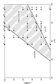
以上の事項以外は実験例8と同様の方法で、実験例1~7及び9~39の脱メタル工程及び脱硫工程を実施した。実験例8と同様の方法で計測した、実験例1~7及び9~39における脱硫触媒の絶対寿命及び相対寿命を下記表1に示す。下表1に示された各実験例のx及びyのプロット図を、図2に示す。図2中の各点に付された番号は、下記表1に示す実験例の番号である。なお、表1中の「V」とは、含バナジウム化合物全体に含まれるバナジウムに対する、易分解性メタル成分に含まれるバナジウムの割合を意味する記号である。

表1及び図2に示すように、yがx-50<y<2.6x-99の範囲にある実験例の脱硫触媒の絶対寿命は300日以上であり、その相対寿命は1以上であることが確認された。一方、yがx-50<y<2.6x-99の範囲から外れる全実験例の脱硫触媒の絶対寿命は300日未満であり、その相対寿命は1未満であることが確認された。つまり、図2に示す直線y=x-50及びy=2.6x-99は、脱硫触媒の絶対寿命が300日以上である実験例のx及びyが分布する領域と、脱硫触媒の絶対寿命が300日未満である実験例のx及びyが分布する領域と、を分ける直線として、本発明者らが上記実験に基づいて導出したものである。なお、図2に示すxとyの関係は、特定の原油に限定されるものではない。
以上のことから、yがx-50<y<2.6x-99の範囲にある場合、yがこの範囲を外れる場合に比べて、脱硫触媒の失活が抑制されたことが確認された。脱硫触媒の失活は、脱メタル触媒の失活に起因することに鑑みれば、yがx-50<y<2.6x-99の範囲にある場合、yがこの範囲を外れる場合に比べて、脱メタル触媒の失活が抑制されたことが確認された。
本発明に係る炭化水素油の製造方法は、常圧残油及び溶剤脱れき油の混合油を原料として用いたガソリン、潤滑油用基油その他化学品等の製造に適している。
Claims (6)
- 常圧残油及び溶剤脱れき油を含む混合油を、水素ガスの存在下で脱メタル触媒に接触させる、脱メタル工程と、
前記脱メタル工程を経た混合油を水素ガスの存在下で脱硫触媒に接触させる、脱硫工程と、
を備え、
前記脱メタル触媒は、少なくとも低反応性触媒を含み、
前記低反応性触媒は、多孔質の担体と、前記担体に担持された第VI族元素と、を有し、
前記低反応性触媒における第VIII族元素の触媒質量基準の含有率が、0質量%以上であり、
前記脱メタル触媒全体に対する高反応性触媒の体積の割合が、0体積%以上であり、
前記高反応性触媒は、多孔質の担体と、前記担体に担持された第VI族元素及び第VIII族元素と、を有し、
前記低反応性触媒における第VIII族元素の触媒質量基準の前記含有率が、前記高反応性触媒における第VIII族元素の触媒質量基準の含有率よりも低く、
前記混合油は、バナジウムを含有する化合物を含み、
前記バナジウムを含有する化合物の一部は、ゲル浸透クロマトグラフィーによって測定される分子量が3000以下である易分解性メタル成分であり、
前記易分解性メタル成分に含まれるバナジウムの量が、前記バナジウムを含有する化合物全体に含まれるバナジウムの量に対してx%であり、前記低反応性触媒の体積の割合が、前記脱メタル触媒全体に対してy体積%であるとき、
下記の不等式が成り立つ、
炭化水素油の製造方法。
0<x<100、
0<y≦100、及び
x-50<y<2.6x-99。 - 前記低反応性触媒における第VI族元素の触媒質量基準の含有率が、前記高反応性触媒における第VI族元素の触媒質量基準の含有率よりも低い、
請求項1に記載の炭化水素油の製造方法。 - 第VI族元素が、モリブデン又はタングステンのうち少なくともいずれか一種であり、
第VIII族元素が、ニッケル又はコバルトのうち少なくともいずれか一種である、
請求項1又は2に記載の炭化水素油の製造方法。 - 前記低反応性触媒における第VI族元素の酸化物の触媒質量基準の含有率が、1質量%以上8質量%未満であり、
前記低反応性触媒における第VIII族元素の酸化物の触媒質量基準の含有率が、0質量%以上1質量%未満である、
請求項1~3のいずれか一項に記載の炭化水素油の製造方法。 - 前記脱メタル工程において、
反応温度が、350~450℃であり、
前記水素ガスの分圧が、5~25MPaであり、
液空間速度が、0.1~3.0h-1であり、
水素/油比が、400~1500Nm3/m3である、
請求項1~4のいずれか一項に記載の炭化水素油の製造方法。 - 前記脱硫工程において、
反応温度が、350~450℃であり、
前記水素ガスの分圧が、5~25MPaであり、
液空間速度が、0.1~3.0h-1であり、
水素/油比が、400~1500Nm3/m3である、
請求項1~5のいずれか一項に記載の炭化水素油の製造方法。
Priority Applications (1)
| Application Number | Priority Date | Filing Date | Title |
|---|---|---|---|
| US14/914,182 US9719032B2 (en) | 2013-08-30 | 2014-07-11 | Hydrocarbon oil production method |
Applications Claiming Priority (2)
| Application Number | Priority Date | Filing Date | Title |
|---|---|---|---|
| JP2013-180567 | 2013-08-30 | ||
| JP2013180567A JP6104762B2 (ja) | 2013-08-30 | 2013-08-30 | 炭化水素油の製造方法 |
Publications (1)
| Publication Number | Publication Date |
|---|---|
| WO2015029618A1 true WO2015029618A1 (ja) | 2015-03-05 |
Family
ID=52586193
Family Applications (1)
| Application Number | Title | Priority Date | Filing Date |
|---|---|---|---|
| PCT/JP2014/068623 Ceased WO2015029618A1 (ja) | 2013-08-30 | 2014-07-11 | 炭化水素油の製造方法 |
Country Status (3)
| Country | Link |
|---|---|
| US (1) | US9719032B2 (ja) |
| JP (1) | JP6104762B2 (ja) |
| WO (1) | WO2015029618A1 (ja) |
Cited By (1)
| Publication number | Priority date | Publication date | Assignee | Title |
|---|---|---|---|---|
| JP2017226799A (ja) * | 2016-06-24 | 2017-12-28 | コスモ石油株式会社 | 直接脱硫方法及び重質炭化水素削減原油 |
Families Citing this family (7)
| Publication number | Priority date | Publication date | Assignee | Title |
|---|---|---|---|---|
| US11788017B2 (en) | 2017-02-12 | 2023-10-17 | Magëmã Technology LLC | Multi-stage process and device for reducing environmental contaminants in heavy marine fuel oil |
| US10604709B2 (en) | 2017-02-12 | 2020-03-31 | Magēmā Technology LLC | Multi-stage device and process for production of a low sulfur heavy marine fuel oil from distressed heavy fuel oil materials |
| US12025435B2 (en) | 2017-02-12 | 2024-07-02 | Magēmã Technology LLC | Multi-stage device and process for production of a low sulfur heavy marine fuel oil |
| US12559689B2 (en) | 2017-02-12 | 2026-02-24 | Magēmā Technology LLC | Multi-stage process and device for treatment heavy marine fuel and resultant composition and the removal of detrimental solids |
| US12281266B2 (en) | 2017-02-12 | 2025-04-22 | Magẽmã Technology LLC | Heavy marine fuel oil composition |
| US10655074B2 (en) | 2017-02-12 | 2020-05-19 | Mag{hacek over (e)}m{hacek over (a)} Technology LLC | Multi-stage process and device for reducing environmental contaminates in heavy marine fuel oil |
| US12071592B2 (en) | 2017-02-12 | 2024-08-27 | Magēmā Technology LLC | Multi-stage process and device utilizing structured catalyst beds and reactive distillation for the production of a low sulfur heavy marine fuel oil |
Citations (4)
| Publication number | Priority date | Publication date | Assignee | Title |
|---|---|---|---|---|
| JPH11279566A (ja) * | 1998-03-31 | 1999-10-12 | Nippon Mitsubishi Oil Corp | 超低硫黄重質油の製造方法 |
| WO2002034865A1 (en) * | 2000-10-24 | 2002-05-02 | Jgc Corpopation | Refined oil and process for producing the same |
| JP2003340281A (ja) * | 2002-05-24 | 2003-12-02 | Inst Fr Petrole | 触媒を使用して炭化水素原料装入物の水素化精製および/または水素化転化の処理方法 |
| JP2012197350A (ja) * | 2011-03-22 | 2012-10-18 | Jx Nippon Oil & Energy Corp | 重質油の水素化精製方法 |
Family Cites Families (3)
| Publication number | Priority date | Publication date | Assignee | Title |
|---|---|---|---|---|
| JP2004010857A (ja) * | 2002-06-11 | 2004-01-15 | Nippon Kecchen Kk | 重質炭化水素油の水素化処理方法 |
| JP2008093493A (ja) * | 2006-10-05 | 2008-04-24 | Idemitsu Kosan Co Ltd | 脱メタル触媒及びそれを用いた重質油の水素化処理方法 |
| JP2010201281A (ja) * | 2009-02-27 | 2010-09-16 | Jgc Catalysts & Chemicals Ltd | 炭化水素油の水素化脱金属触媒及びそれを用いた水素化処理方法 |
-
2013
- 2013-08-30 JP JP2013180567A patent/JP6104762B2/ja active Active
-
2014
- 2014-07-11 WO PCT/JP2014/068623 patent/WO2015029618A1/ja not_active Ceased
- 2014-07-11 US US14/914,182 patent/US9719032B2/en not_active Expired - Fee Related
Patent Citations (4)
| Publication number | Priority date | Publication date | Assignee | Title |
|---|---|---|---|---|
| JPH11279566A (ja) * | 1998-03-31 | 1999-10-12 | Nippon Mitsubishi Oil Corp | 超低硫黄重質油の製造方法 |
| WO2002034865A1 (en) * | 2000-10-24 | 2002-05-02 | Jgc Corpopation | Refined oil and process for producing the same |
| JP2003340281A (ja) * | 2002-05-24 | 2003-12-02 | Inst Fr Petrole | 触媒を使用して炭化水素原料装入物の水素化精製および/または水素化転化の処理方法 |
| JP2012197350A (ja) * | 2011-03-22 | 2012-10-18 | Jx Nippon Oil & Energy Corp | 重質油の水素化精製方法 |
Cited By (1)
| Publication number | Priority date | Publication date | Assignee | Title |
|---|---|---|---|---|
| JP2017226799A (ja) * | 2016-06-24 | 2017-12-28 | コスモ石油株式会社 | 直接脱硫方法及び重質炭化水素削減原油 |
Also Published As
| Publication number | Publication date |
|---|---|
| US20160200990A1 (en) | 2016-07-14 |
| US9719032B2 (en) | 2017-08-01 |
| JP6104762B2 (ja) | 2017-03-29 |
| JP2015048398A (ja) | 2015-03-16 |
Similar Documents
| Publication | Publication Date | Title |
|---|---|---|
| JP6104762B2 (ja) | 炭化水素油の製造方法 | |
| CA2880515C (en) | Residue hydrocracking | |
| JP6770953B2 (ja) | 水素化処理油の製造方法及び接触分解油の製造方法 | |
| Pérez-Romo et al. | Morphological and structural study of the Si deposition on the sulfided NiMo/γ-Al2O3 catalyst: effect on the support | |
| JP4576334B2 (ja) | 軽油留分の水素化処理方法 | |
| JP5406629B2 (ja) | 高芳香族炭化水素油の製造方法 | |
| JP2011079995A (ja) | 高芳香族炭化水素油の製造方法 | |
| Quitian et al. | Characterization of upgraded oil fractions obtained by slurry-phase hydrocracking at low-severity conditions using analytical and ore catalysts | |
| JP6104761B2 (ja) | 炭化水素油の製造方法 | |
| JP5563491B2 (ja) | 重質炭化水素油の水素化処理方法 | |
| JP2013249385A (ja) | 重質油の水素化処理方法 | |
| JP5751876B2 (ja) | 重質油の水素化精製方法 | |
| JP5291940B2 (ja) | ナフサ留分の水素化精製方法 | |
| JP6548223B2 (ja) | 燃料油基材の製造方法 | |
| Alfadhli et al. | Performance assessment of NiMo/γ-Al2O3 catalysts for upgrading KEC-AR: An assessment of selected apparent kinetic parameters of selected hydrotreating reactions | |
| JP2005314657A (ja) | 重質炭化水素油の水素化処理方法 | |
| Amora et al. | Deactivation analysis of industrial spent catalysts applied to lube oil hydrotreating in a pilot plant | |
| JP7011479B2 (ja) | 炭化水素油の製造方法 | |
| US20200199464A1 (en) | Naphthenic compositions derived from fcc process fractions | |
| JP4771509B2 (ja) | 軽油留分の水素化精製方法 | |
| JP5207923B2 (ja) | 精製炭化水素油の製造方法 | |
| JP2001089771A (ja) | 重質炭化水素油の水素化脱硫方法 |
Legal Events
| Date | Code | Title | Description |
|---|---|---|---|
| 121 | Ep: the epo has been informed by wipo that ep was designated in this application |
Ref document number: 14839756 Country of ref document: EP Kind code of ref document: A1 |
|
| WWE | Wipo information: entry into national phase |
Ref document number: 14914182 Country of ref document: US |
|
| NENP | Non-entry into the national phase |
Ref country code: DE |
|
| 122 | Ep: pct application non-entry in european phase |
Ref document number: 14839756 Country of ref document: EP Kind code of ref document: A1 |