WO2015029405A1 - 記録装置 - Google Patents
記録装置 Download PDFInfo
- Publication number
- WO2015029405A1 WO2015029405A1 PCT/JP2014/004339 JP2014004339W WO2015029405A1 WO 2015029405 A1 WO2015029405 A1 WO 2015029405A1 JP 2014004339 W JP2014004339 W JP 2014004339W WO 2015029405 A1 WO2015029405 A1 WO 2015029405A1
- Authority
- WO
- WIPO (PCT)
- Prior art keywords
- ink
- recording apparatus
- liquid
- holding
- unit
- Prior art date
- Legal status (The legal status is an assumption and is not a legal conclusion. Google has not performed a legal analysis and makes no representation as to the accuracy of the status listed.)
- Ceased
Links
Images


Classifications
-
- B—PERFORMING OPERATIONS; TRANSPORTING
- B41—PRINTING; LINING MACHINES; TYPEWRITERS; STAMPS
- B41J—TYPEWRITERS; SELECTIVE PRINTING MECHANISMS, i.e. MECHANISMS PRINTING OTHERWISE THAN FROM A FORME; CORRECTION OF TYPOGRAPHICAL ERRORS
- B41J2/00—Typewriters or selective printing mechanisms characterised by the printing or marking process for which they are designed
- B41J2/005—Typewriters or selective printing mechanisms characterised by the printing or marking process for which they are designed characterised by bringing liquid or particles selectively into contact with a printing material
- B41J2/01—Ink jet
- B41J2/17—Ink jet characterised by ink handling
- B41J2/175—Ink supply systems ; Circuit parts therefor
- B41J2/17503—Ink cartridges
- B41J2/1752—Mounting within the printer
-
- B—PERFORMING OPERATIONS; TRANSPORTING
- B41—PRINTING; LINING MACHINES; TYPEWRITERS; STAMPS
- B41J—TYPEWRITERS; SELECTIVE PRINTING MECHANISMS, i.e. MECHANISMS PRINTING OTHERWISE THAN FROM A FORME; CORRECTION OF TYPOGRAPHICAL ERRORS
- B41J2/00—Typewriters or selective printing mechanisms characterised by the printing or marking process for which they are designed
- B41J2/005—Typewriters or selective printing mechanisms characterised by the printing or marking process for which they are designed characterised by bringing liquid or particles selectively into contact with a printing material
- B41J2/01—Ink jet
- B41J2/17—Ink jet characterised by ink handling
- B41J2/175—Ink supply systems ; Circuit parts therefor
- B41J2/17503—Ink cartridges
- B41J2/17513—Inner structure
-
- B—PERFORMING OPERATIONS; TRANSPORTING
- B41—PRINTING; LINING MACHINES; TYPEWRITERS; STAMPS
- B41J—TYPEWRITERS; SELECTIVE PRINTING MECHANISMS, i.e. MECHANISMS PRINTING OTHERWISE THAN FROM A FORME; CORRECTION OF TYPOGRAPHICAL ERRORS
- B41J29/00—Details of, or accessories for, typewriters or selective printing mechanisms not otherwise provided for
- B41J29/02—Framework
-
- B—PERFORMING OPERATIONS; TRANSPORTING
- B41—PRINTING; LINING MACHINES; TYPEWRITERS; STAMPS
- B41J—TYPEWRITERS; SELECTIVE PRINTING MECHANISMS, i.e. MECHANISMS PRINTING OTHERWISE THAN FROM A FORME; CORRECTION OF TYPOGRAPHICAL ERRORS
- B41J29/00—Details of, or accessories for, typewriters or selective printing mechanisms not otherwise provided for
- B41J29/12—Guards, shields or dust excluders
- B41J29/13—Cases or covers
-
- B—PERFORMING OPERATIONS; TRANSPORTING
- B41—PRINTING; LINING MACHINES; TYPEWRITERS; STAMPS
- B41J—TYPEWRITERS; SELECTIVE PRINTING MECHANISMS, i.e. MECHANISMS PRINTING OTHERWISE THAN FROM A FORME; CORRECTION OF TYPOGRAPHICAL ERRORS
- B41J2/00—Typewriters or selective printing mechanisms characterised by the printing or marking process for which they are designed
- B41J2/005—Typewriters or selective printing mechanisms characterised by the printing or marking process for which they are designed characterised by bringing liquid or particles selectively into contact with a printing material
- B41J2/01—Ink jet
- B41J2/17—Ink jet characterised by ink handling
- B41J2/175—Ink supply systems ; Circuit parts therefor
- B41J2/17503—Ink cartridges
- B41J2/17513—Inner structure
- B41J2002/17516—Inner structure comprising a collapsible ink holder, e.g. a flexible bag
Definitions
- the present invention relates to a recording apparatus.
- an ink jet printer that performs printing by ejecting ink from a recording head to a sheet or the like is known as a type of recording apparatus.
- the external ink supply device in order to supply the ink continuously and stably to the printer head when performing a relatively large amount of printing, the external ink supply device (separate from the main device of the ink jet printer)
- a configuration including a liquid supply device) and supplying ink to a printer head see, for example, Patent Document 1).
- Such a liquid supply device is provided with a large capacity ink pack (liquid container), and the ink is supplied by an ink supply tube that communicates the liquid supply device with the printer head in the main device.
- a holder for holding a large capacity ink pack is provided separately from the main unit of the ink jet printer. Therefore, there is a problem that the ink jet printer is upsized. Further, even in the configuration in which a large capacity ink pack is held in the main unit of the ink jet printer, when the large capacity ink pack is disposed on one side of the main unit, the balance is bad and the main unit becomes unstable.
- the present invention has been made to solve at least a part of the above-described problems, and can be realized as the following modes or application examples.
- a recording head capable of ejecting a liquid onto a recording medium, a recording medium holding unit for holding the recording medium, and the recording medium from the recording medium holding unit Formed on the outer surface of the case, which accommodates the conveyance unit for conveying the ink, the recording head, and the conveyance unit, and the recording medium holding unit is inserted, and the recording medium holding unit is inserted And an insertion slot.
- first holding body disposed on one outer surface adjacent to the outer surface on which the insertion port of the housing is formed, and holding the first liquid container for containing the liquid
- the housing A second holding body disposed on the other outer surface adjacent to the outer surface on which the insertion port is formed, and holding a second liquid container for containing the liquid, the first liquid container, and And a supply unit configured to supply the liquid from the second liquid container to the recording head of the housing.
- the first holding body and the second holding body are different in size.
- the case is provided with the holding body disposed on the outer side of both sides adjacent to the outer side formed with the insertion port of the housing and holding the liquid container, and the sizes of the holding bodies on both sides are different. .
- the necessary size and number of liquid containers in accordance with the amount of use which differs depending on the type of liquid. Therefore, the enlargement of the recording apparatus can be suppressed.
- the liquid container is provided on both sides of the case, the weight balance on the left and right is improved, and the main device is prevented from becoming unstable.
- Application Example 2 In Application Example 1, at least one of depth, width, and height of the holding bodies on both sides is different.
- the sizes of the holders on both sides are different.
- Application Example 3 In Application Example 1 or 2, the size of the first holding body is smaller than the size of the second holding body.
- the number of the second liquid containers held by the second holding member is the number of the first liquid containers held by the first holding member. It is characterized by more than.
- the plurality of second liquid containers are characterized in that they are held by the second holding body in a state in which the plurality of second liquid containers overlap with each other. According to this application example, since the width of the second holding body can be suppressed, the weight balance of the recording apparatus can be improved.
- the volume of the first liquid container is characterized by being larger than any volume of the second liquid container. According to this application example, the weight balance of the recording apparatus can be improved with respect to the plurality of second liquid containers.
- a reading unit for reading an image drawn on a document and a conveyance unit for conveying the document to the reading unit, the conveyance unit including: It is characterized in that it is disposed on the side of the first holder. According to this application example, even if the total volume of the first liquid container is smaller than the total volume of the second liquid container, the weight of the recording apparatus is improved by the transport unit having a weight. Can.
- the reading unit is provided for reading an image drawn on a document placed on a document table, and the position of the top of the holder on both sides is It is characterized in that it is at a lower position than the document table. According to this application example, the operability when the user places a document on the reading unit and removes the document from the reading unit is good.
- Application Example 10 In Application Example 2, the liquid container having a large capacity is held by the smaller one of the holding bodies on both sides, and the liquid having a small volume is held by the larger holding body.
- the container is held, and the larger holder is characterized in that a larger number of the liquid containers are held than the smaller holder.
- Application Example 11 In Application Example 2, at least one of the liquid containers held by the same number of liquid containers is held by the holding members on both sides and held by the larger holding member.
- the liquid container is characterized by having a larger volume than the liquid container.
- Application Example 12 In any one of Application Example 1, Application Example 2 and Application Example 10, the holding on the right side of the holding members on both sides in the direction seen from the side where the insertion port is formed, in the housing
- the body is characterized in that a larger number of the liquid containers are held than the holder on the left side.
- the operability when the right-handed user attaches and detaches the liquid container to the holder is good.
- Application Example 13 In any one of Application Example 1, Application Example 2, and Application Example 10 to Application Example 12, the liquid containing portion in which a convex portion which is a convex on the outside is formed and held in the lower portion of the holder.
- the body is characterized by being arranged corresponding to the convex part.
- a part of the liquid container can be held in the recess formed on the inside of the holder along the protrusion.
- the liquid container is characterized in that it is flexible.
- Application Example 15 In Application Example 13 or Application Example 14, a window is formed on the upper side of the convex portion.
- the user can visually recognize the consumption amount of the liquid contained in the liquid container.
- FIG. 1 is an external perspective view of a recording apparatus. The figure which looked at the recording device in the state which removed the auto document feeder from the front side.
- FIG. 6 is a perspective view of the recording apparatus with the lid of the ink supply device removed.
- FIG. 2 is a perspective view of an ink container.
- FIG. 2 is a perspective view of the recording apparatus in a state in which the upper part of the housing is removed.
- (A) is an external appearance perspective view showing a portion on the side provided with the ink supply device in Embodiment 2
- (b) is a view of the portion on the side provided with the ink supply device seen from the front
- (c) The figure which shows schematic structure of a locking mechanism.
- FIG. 1 is an external perspective view of an ink jet printer (hereinafter, referred to as a printer) 11 as a recording apparatus in the present embodiment.
- the printer 11 includes a printing unit 12 that ejects ink (liquid) to form an image, and a main body device 14 having a reading unit 13 that reads an original G (medium), and an ink supply device 15a that supplies ink to the printing unit 12 And 15b.
- the first holder, the ink supply device 15a is mounted on the left side of the main unit 14, and the second holder, the ink supply unit 15b, is mounted on the right side of the main unit 14.
- the reading unit 13 is disposed on the printing unit 12.
- the reading unit 13 is provided with a not-shown document table formed of a transparent plate-like member such as glass, and can read the document G placed on the document table.
- an auto document feeder 16 connected to an upper end portion of a rear surface of the reading unit 13 via a hinge unit (not shown) is disposed.
- the auto document feeder 16 can sequentially feed a plurality of stacked originals G onto a reading window (not shown) formed of a transparent plate-like member such as glass while inverting the originals G one by one to read the originals G. It is.
- the auto document feeder 16 is provided with a transport section on the side of the ink supply device 15a attached to the left side of the main body 14 from the mounting table on which the document G is mounted. Therefore, the automatic document feeder 16 is configured to be heavy on the side where the transport unit is provided.
- a sheet cassette 29 which is a recording medium holding unit is provided in the opening 30 formed on the front side of the housing 25 so as to be insertable and removable in the front and rear direction.
- the opening 30 is an insertion port through which the sheet cassette 29 is detachably mounted to the housing 25.
- a sheet discharge tray 32 is provided on the upper side of the sheet cassette 29 so as to be extensible and contractible in the front-rear direction.
- a plurality of sheets of paper are placed on the sheet cassette 29 in a stacked state.
- the sheets placed on the sheet cassette 29 are supplied one by one to the inside of the housing 25, and the printed sheet is discharged from the discharge port 31 and placed on the discharge tray 32.
- an additional cassette unit 141 is provided under the housing 25, an additional cassette unit 141 is provided.
- the additional cassette unit 141 is provided with a sheet cassette 140 which is a recording medium holding unit which can be inserted and removed in the front and rear direction.
- the lid body 21 of the case 18 is open at the side of the container body 20, and is in the shape of a covered rectangular box which is long in the front-rear direction and shallower than the container body 20.
- the lid 21 is connected to the upper end of the rear surface of the container body 20 via a hinge (not shown). Therefore, the lid 21 pivots about the hinge portion when the lid 21 is opened and closed. That is, the lid 21 is opened from the front side of the container body 20 and closed on the front side of the container body 20.
- the container main body 20 is a bottom wall rectangular box-shaped bottom wall forming member 50, and an inner half of a side wall (a half on the side of the main unit 14 in the left-right direction) and a plate-like inner wall forming member curved in a substantially U shape. 51, a plate-like outer wall forming member 52 which forms an outer half of the side wall (a half opposite to the main unit 14 in the left-right direction) and which is curved in a substantially U shape, and a hollow constituting a peripheral portion of the opening And an edge member 53 having a rectangular frame shape.
- the container main body 20 is configured by combining an inner side wall forming member 51 as an example of a dividing member and an outer wall forming member 52 as an example of a dividing member. That is, the side wall of the container body 20 is configured by combining the inner side wall forming member 51 and the outer side wall forming member 52 which are two divided members.
- a lock mechanism 22 is provided on the front side of the lid 21 and the edge member 53 of the ink supply devices 15a and 15b.
- the lock mechanism 22 can keep the lid 21 closed with respect to the container main body 20 by means of a so-called padlock 60.
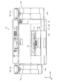
- FIG. 2 is a front view of the printer 11 with the auto document feeder 16 removed from the state of FIG.
- the broken line 13a indicates the position in the height direction of the document table on which the document G is placed.
- the position of the upper end 21a of the lid 21 is at the same position as the position 13a in the height direction of the reading surface (document table) or lower than the position 13a.
- the user lifts and turns the auto document feeder 16 of FIG. 1 to open the document table, and then places the document G on the document table, and the image of the document G is read by the reading unit 13
- the operability is good in the operation until the document G is removed from the document table after reading the document G.
- the document G which is exposed particularly in the left and right direction of the document table does not interfere with the ink supply devices 15a and 15b, and the operability is good.
- the height of the upper surface of the ink supply devices 15a and 15b is set to be substantially the same as the height of the document table, the projected document G can be supported, and the document G is distorted due to bending. Damage can be prevented.
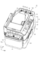
- FIG. 3 is a perspective view of the printer 11 with the lid 21 of the ink supply devices 15a and 15b removed.
- the ink supply device 15a is detachably provided with one ink container 17a for storing monochrome ink as a first liquid container.
- the ink supply device 15b is detachably provided with three ink containers 17b that respectively store yellow, magenta, and cyan color inks, which are the second liquid containers.
- the ink capacity capable of containing the ink in the ink container 17a is larger than the ink capacity capable of containing the ink in the ink container 17b. Further, the ink capacities of the three ink containers 17b are substantially the same.
- the ink capacity of one ink container 17a and the total ink capacity of the three ink containers 17b are the same or substantially the same.
- the heavy transport unit of the auto document feeder 16 holds the ink container 17a.
- the arrangement on the side of the supply device 15a is preferable for improving the weight balance of the printer.
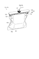
- FIG. 4 is a perspective view of the ink containers 17a and 17b.
- the ink containers 17a and 17b include an ink bag 90 for containing ink.
- a support member (hanger member) 92 is attached to the upper end side of the ink bag 90. That is, the ink bag 90 is engaged with the support member 92.
- the ink bag 90 is formed by welding the peripheries of the two flexible films 90a in a state where a cylindrical ink lead-out portion (not shown) is sandwiched between the peripheries of the two rectangular flexible films 90a. Be done.
- the support members 92 of the ink containers 17 a and 17 b are provided with a first support member 105 and a second support member 106 attached so as to sandwich the upper end portion with respect to the upper end portion of the ink bag 90. Further, at both end portions of the second support member 106, columnar convex portions 123 which are inserted into ink bag through holes (not shown) formed in the ink bag 90 are respectively provided in a protruding manner. Further, the second support member 106 is formed with an engagement notch portion 130 which engages with the convex portion 123 inserted into the ink bag through hole.
- the three ink containers 17b are in a concave portion (not shown) in the container main body 20 at an angle (for example, 30 degrees) at which the longitudinal direction of the first support member 105 is inclined with respect to the left and right direction. Hold on. With this configuration, the width of the container main body 20 can be suppressed, so that the weight balance of the printer can be improved.
- a valve body (not shown) is provided above the ink containers 17a and 17b, and the valve body operates by rotating the cap 87 in the direction to push it down, and the inside of the ink containers 17a and 17b
- the connection tubes 37a and 37b are in communication with each other.
- the depth length of the case 18 of the ink supply device 15a is shorter than the depth length of the case 18 of the ink supply device 15b.
- the positions of the end portions on the front side of the ink supply device 15a and the ink supply device 15b are substantially the same position in the front-rear direction, but the position on the back side of the ink supply device 15a is the back side of the ink supply device 15b. It is on the front side of the position. Therefore, the ink supply device 15 a is not disposed on the left rear surface of the housing 25.
- the user connects a plug (not shown) connected to the power cord to supply AC power to a plug receptacle (not shown) provided on the left rear surface of the housing 25. Connection work can be facilitated.
- the length L1 of the width of the case 18 of the ink supply device 15a is shorter than the length L2 of the width of the case 18 of the ink supply device 15b, and the length in the height direction of the case 18 of the ink supply device 15a is the ink It is shorter than the length in the height direction of the case 18 of the supply device 15b.
- the sizes of the case 18 of the ink supply device 15a and the case 18 of the ink supply device 15b are different.
- FIG. 5 is a perspective view of the printer 11 with the top of the housing 25 removed.
- the printing unit 12 includes a substantially rectangular parallelepiped casing 25 which is long in the left-right direction.
- a support 26 for supporting the sheet P as a recording medium is provided at a central portion in the housing 25, a support 26 for supporting the sheet P as a recording medium is provided at a central portion in the housing 25, a support 26 for supporting the sheet P as a recording medium is provided.
- a carriage 27 capable of reciprocating in the left-right direction, which is the main scanning direction, is provided.
- a recording head 28 that ejects ink so as to be exposed from the lower surface of the carriage 27 is supported.
- the recording head 28 faces the support 26.
- the recording head 28 ejects ink from a plurality of nozzles (not shown) to the sheet P conveyed from the rear side to the front side on the support base 26 while the carriage 27 moves in the left-right direction. Print on P.
- the sheet cassette 29 is provided below the support 26 in the housing 25.
- the sheets P in the sheet cassette 29 are fed from the rear side onto the support 26 while being reversed one by one by a sheet feeding mechanism (not shown).
- the sheet P printed on the support base 26 is sequentially discharged from the sheet discharge port 31 of FIG. 1 configured by an area above the sheet cassette 29 in the opening 30.
- a holder case 34 in the shape of a rectangular box whose front side is open is provided.
- four hollow ink supply needles (not shown) aligned in the left-right direction are provided.
- Each ink supply needle extends in the front-rear direction and penetrates the side wall of the holder case 34.
- One end of the flexible ink supply tube 36 is connected to the rear end of each ink supply needle, and the other end of the ink supply tube 36 is connected to the recording head 28.
- connection tube 37a One end of one flexible connection tube 37a is connected to the front end of the ink supply needle, and the other end of the connection tube 37a is connected to the ink container 17a accommodated in the ink supply device 15a. (See Figure 3).
- connection tube 37b One end of each of the three flexible connection tubes 37b is connected to the front end of each ink supply needle, and the other end of the connection tube 37b is connected to each ink container 17b accommodated in the ink supply device 15b. (See Figure 3).
- a valve body (not shown) is provided above the ink containers 17a and 17b, and the valve body operates by rotating the cap 87 in the direction to push it down, and the inside of the ink containers 17a and 17b
- the connection tubes 37a and 37b are in communication with each other.
- monochrome ink is supplied from the ink container 17a accommodated in the ink supply device 15a to the recording head 28 through the connection tube 37a, the ink supply needle, and the ink supply tube 36.
- color ink of yellow ink, magenta ink, and cyan ink is supplied to the recording head 28 from the ink container 17b accommodated in the ink supply device 15b through the connection tube 37b, the ink supply needle, and the ink supply tube 36. Be done.
- the sheet cassette 29 in the present embodiment constitutes a recording medium holding unit
- the ink containers 17a and 17b constitute a liquid container
- the case 18 constitutes a holder.
- the printer 11 includes a recording head capable of ejecting ink onto the sheet P, a sheet cassette 29 for holding the sheet P, a conveyance unit for conveying the sheet P to the recording head, a recording head and a conveyance unit A housing 25 in which the paper cassette 29 is inserted, and an insertion port (opening 30) formed on the outer surface of the housing 25 for inserting the paper cassette 29, and an ink container 17a for containing ink. 17b and a case 18 which is disposed on the outer surface on both sides adjacent to the outer surface on which the opening 30 of the housing 25 is formed, and supplies ink to the inside of the housing 25 from the ink container.
- Supply portion including at least the connection tubes 37a and 37b), and the sizes of the cases 18 on both sides are different.
- the size and the number of the ink containers 17a and 17b can be changed according to the amount of use which differs depending on the type of ink, and the case 18 can be provided. Therefore, the enlargement of the printer 11 can be suppressed. Further, since the ink containers 17a and 17b are provided on both sides of the housing 25, the weight balance on the left and right is improved, and the main body device 14 is prevented from becoming unstable.
- the depth, width, and height may be different, but at least one of the depth, width, and height may be different.
- the ink container 17a having a large capacity is held by the case 18 of the smaller ink supply device 15a of the cases 18 on both sides, and the ink container having a smaller capacity is held by the case 18 of the larger ink supply device 15b.
- 17b is held, and a larger number of ink containers 17b (three) are held in the larger right case 18 than the ink containers 17a (one) of the smaller left case 18.
- the amount of monochrome ink used is larger than the amount of color ink used.
- the ink containers 17a and 17b can be disposed in accordance with the usage amount that differs depending on the type of ink.
- the same number of ink containers are held in the cases 18 on both sides, and at least one of the ink containers held in the larger case has a larger capacity than the other ink containers. Good.
- the ink container can be disposed in accordance with the amount of use which differs depending on the type of ink such as monochrome ink or color ink.
- the case 18 on the right side is a single ink container 17a of the case 18 on the left side. A large number of three ink containers 17b are held.
- the ink containers 17a and 17b are flexible. As a result, the ink bag 90 of the ink containers 17a and 17b shrinks in accordance with the consumption of the ink, so that the inside of the ink bag 90 has a negative pressure, and the ink can not be supplied to the recording head 28 side. Can be prevented. In addition, since the transport unit of the heavy document feeder 16 is provided on the side of the smaller ink supply device 15a of the cases 18 on both sides, the weight balance between the left and right is improved.
- the first embodiment describes the case 18 in which the pivot shaft of the lid 21 is provided on the back side and the front side is open, but in the second embodiment, the pivot shaft extending in the front-rear direction is at the lower portion of the lid 21.
- the pivot shaft extending in the front-rear direction is at the lower portion of the lid 21.
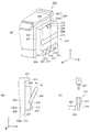
- FIG. 6A is an external perspective view showing a portion on the side where the ink supply device 210 is provided in the second embodiment.
- FIG. 6B is a front view of a portion on the side where the ink supply device 210 is provided.
- the case 209 of the ink supply device 210 is composed of a container body 207 and a lid 208.
- the lid 208 is pivoted in the arrow direction with a pivot shaft 216 provided at the lower part of the lid 208 and extending in the longitudinal direction in the axial direction as a fulcrum. Thereby, the right side of the lid 208 is provided to be openable.
- the main body device 203 includes a reading unit 201 and a printing unit 202. On the right side of the reading unit 201, there is formed a flange portion 204 which protrudes to the right from the wall surface of the housing 205 which accommodates the printing unit 202. That is, as shown in FIG. 6B, the hook portion 204 is at a position overlapping the container body 207 in the left-right direction. As a result, the printer 200 can be prevented from increasing in size.
- the lower portion of the lid 208 is thinner than the other portions, and the lower portion is shaped to be recessed.
- a convex portion 211 protruding outward from the recessed wall surface 212 of the lid 208 is formed.
- the protrusion amount of the convex portion is equal to that of the other non-shrinking region.
- the projection has a relatively projecting shape.
- a recess (not shown) formed along the shape of the convex portion 211 is formed on the lower inner wall surface of the lid 208.
- the lid 208 is provided with a transparent member 213 having transparency.
- the ink container accommodated in the container body 207 functions as a visible window. Therefore, the degree of shrinkage of the ink bags of all the ink containers in the case 209 can be viewed from the front side of the case 209 from the outside of the transparent member 213. Therefore, the replacement time of each ink container can be recognized from the degree of shrinkage of the ink bag 90 of each ink container.
- the lid 208 shown in FIG. 6A is provided with an opening / closing lever 214 when the lid 208 is opened and closed.
- the opening and closing lever 214 is provided at a position between the plurality of ink containers accommodated in the container body 207.
- the opening / closing lever 214 includes a lock mechanism for fixing the container body 207 and the lid 208 in a closed state, and a structure such as a hook (not shown), which requires an installation space for them. Even in such a case, by providing the opening / closing lever 214 at a position between the plurality of ink containers accommodated in the container main body 207, the length of the width of the case 209 can be shortened.
- FIG. 6C is a view showing a schematic configuration of the lock mechanism 215. As shown in FIG.
- the lock mechanism 215 is configured by a so-called cylinder lock.
- a holding member 217 is provided on the top of the lid 208.
- the holding member 217 is rotatably provided with a turning member 218.
- a lever 219 is provided at the end of the pivoting member 218. When the user inserts the key 221 into the opening of the pivoting member 218 and pivots it, the lever 219 pivots and engages with the engaging portion 220 provided on the container body 207, and the lid 208 is a container The main body 207 is closed.
- an additional cassette unit 206 is provided separately from a paper cassette (not shown) provided so as to be insertable into and removable from the insertion port of the housing 205.
- the lower end of the case 209 is located below the bottom 205 a of the housing 205, and the lower end of the case 209 is located above the bottom 206 a of the additional cassette unit 206.
- a concave handle portion 222 is provided long in the front-rear direction at the right side corner portion of the bottom portion 206 a of the additional cassette unit 206.
- the handle portion 222 is provided at a position not overlapping the lid 208 and the container body 207 in the vertical direction.
Landscapes
- Ink Jet (AREA)
- Impression-Transfer Materials And Handling Thereof (AREA)
Priority Applications (5)
| Application Number | Priority Date | Filing Date | Title |
|---|---|---|---|
| US14/913,572 US9498968B2 (en) | 2013-08-29 | 2014-08-22 | Recording apparatus |
| CN201480045967.XA CN105517805B (zh) | 2013-08-29 | 2014-08-22 | 记录装置 |
| EP14839612.0A EP3040204B1 (en) | 2013-08-29 | 2014-08-22 | Storage device |
| PH12016500259A PH12016500259A1 (en) | 2013-08-29 | 2016-02-05 | Recording apparatus |
| US15/297,915 US9821559B2 (en) | 2013-08-29 | 2016-10-19 | Recording apparatus |
Applications Claiming Priority (2)
| Application Number | Priority Date | Filing Date | Title |
|---|---|---|---|
| JP2013177661A JP6330275B2 (ja) | 2013-08-29 | 2013-08-29 | 記録装置 |
| JP2013-177661 | 2013-08-29 |
Related Child Applications (2)
| Application Number | Title | Priority Date | Filing Date |
|---|---|---|---|
| US14/913,572 A-371-Of-International US9498968B2 (en) | 2013-08-29 | 2014-08-22 | Recording apparatus |
| US15/297,915 Continuation US9821559B2 (en) | 2013-08-29 | 2016-10-19 | Recording apparatus |
Publications (1)
| Publication Number | Publication Date |
|---|---|
| WO2015029405A1 true WO2015029405A1 (ja) | 2015-03-05 |
Family
ID=52585995
Family Applications (1)
| Application Number | Title | Priority Date | Filing Date |
|---|---|---|---|
| PCT/JP2014/004339 Ceased WO2015029405A1 (ja) | 2013-08-29 | 2014-08-22 | 記録装置 |
Country Status (6)
| Country | Link |
|---|---|
| US (2) | US9498968B2 (enExample) |
| EP (1) | EP3040204B1 (enExample) |
| JP (1) | JP6330275B2 (enExample) |
| CN (1) | CN105517805B (enExample) |
| PH (1) | PH12016500259A1 (enExample) |
| WO (1) | WO2015029405A1 (enExample) |
Cited By (7)
| Publication number | Priority date | Publication date | Assignee | Title |
|---|---|---|---|---|
| WO2016021171A1 (ja) * | 2014-08-05 | 2016-02-11 | セイコーエプソン株式会社 | 複合装置 |
| WO2016199420A1 (ja) * | 2015-06-09 | 2016-12-15 | セイコーエプソン株式会社 | 液体噴射装置、タンクユニット、プリンター |
| JP2017113968A (ja) * | 2015-12-24 | 2017-06-29 | セイコーエプソン株式会社 | タンクユニット、プリンター |
| JP2017113969A (ja) * | 2015-12-24 | 2017-06-29 | セイコーエプソン株式会社 | プリンター |
| US9821559B2 (en) | 2013-08-29 | 2017-11-21 | Seiko Epson Corporation | Recording apparatus |
| US20240300253A1 (en) * | 2023-03-10 | 2024-09-12 | Seiko Epson Corporation | Recording device |
| US12502902B2 (en) * | 2023-03-10 | 2025-12-23 | Seiko Epson Corporation | Recording device |
Families Citing this family (2)
| Publication number | Priority date | Publication date | Assignee | Title |
|---|---|---|---|---|
| JP6631019B2 (ja) * | 2015-03-12 | 2020-01-15 | セイコーエプソン株式会社 | 液体収容体ユニット |
| JP7247746B2 (ja) * | 2019-05-21 | 2023-03-29 | セイコーエプソン株式会社 | 記録装置 |
Citations (4)
| Publication number | Priority date | Publication date | Assignee | Title |
|---|---|---|---|---|
| JPH106525A (ja) * | 1996-06-26 | 1998-01-13 | Ricoh Co Ltd | インクカートリッジ梱包体及びインクジェット記録装置 |
| JP2007044885A (ja) * | 2005-08-05 | 2007-02-22 | Seiko Epson Corp | インクジェット式記録装置、その制御方法、そのメンテナンス方法、及びそのメンテナンス用カートリッジ |
| JP2009202346A (ja) | 2008-02-26 | 2009-09-10 | Mimaki Engineering Co Ltd | プリンタシステムおよび外部インク供給装置 |
| JP2013123846A (ja) * | 2011-12-14 | 2013-06-24 | Seiko Epson Corp | 記録装置 |
Family Cites Families (20)
| Publication number | Priority date | Publication date | Assignee | Title |
|---|---|---|---|---|
| US5369429A (en) * | 1993-10-20 | 1994-11-29 | Lasermaster Corporation | Continuous ink refill system for disposable ink jet cartridges having a predetermined ink capacity |
| JP3572854B2 (ja) * | 1996-04-05 | 2004-10-06 | セイコーエプソン株式会社 | インクジェットプリンタ及びダンパ |
| JPH1158792A (ja) * | 1997-08-21 | 1999-03-02 | Seiko Epson Corp | インクジェット式記録装置およびこれに用いるインクカートリッジ |
| JP2000280570A (ja) * | 1999-03-31 | 2000-10-10 | Brother Ind Ltd | 画像形成装置 |
| US6338553B1 (en) * | 2000-05-15 | 2002-01-15 | Hewlett-Packard Company Intellectual Property Administration | Ink supply tube guiding system for large format printer |
| US7370949B2 (en) * | 2002-02-28 | 2008-05-13 | Seiko Epson Corporation | Liquid supplying member, method of manufacturing the same, and liquid ejection apparatus incorporating the same |
| US7008051B2 (en) * | 2002-10-10 | 2006-03-07 | Akermalm Per G | Expanded ink supply system for ink jet printers |
| JP4193719B2 (ja) * | 2003-03-05 | 2008-12-10 | セイコーエプソン株式会社 | 液体収容体、液体噴射装置及び液体収容ケース |
| JP4645682B2 (ja) * | 2007-06-20 | 2011-03-09 | セイコーエプソン株式会社 | 流体噴射装置およびその製造方法 |
| EP2014889A1 (en) | 2007-06-20 | 2009-01-14 | Ford Global Technologies, LLC | A method for thermally managing an internal combustion engine |
| WO2008156209A1 (ja) | 2007-06-20 | 2008-12-24 | Seiko Epson Corporation | 流体噴射装置およびその製造方法 |
| JP4766011B2 (ja) | 2007-06-20 | 2011-09-07 | セイコーエプソン株式会社 | 流体噴射装置およびその製造方法 |
| JP2013023846A (ja) | 2011-07-19 | 2013-02-04 | Nippon Hume Corp | 推進管の連結部構造 |
| JP2013123847A (ja) * | 2011-12-14 | 2013-06-24 | Seiko Epson Corp | 液体供給システム |
| JP5998471B2 (ja) * | 2011-12-20 | 2016-09-28 | セイコーエプソン株式会社 | アダプター |
| JP5948929B2 (ja) * | 2012-02-10 | 2016-07-06 | セイコーエプソン株式会社 | 記録装置 |
| JP2013180465A (ja) * | 2012-03-01 | 2013-09-12 | Seiko Epson Corp | インクジェット記録装置 |
| JP5991462B2 (ja) * | 2012-02-29 | 2016-09-14 | セイコーエプソン株式会社 | 記録装置 |
| JP6221303B2 (ja) * | 2013-03-29 | 2017-11-01 | セイコーエプソン株式会社 | 液体噴射装置 |
| JP6330275B2 (ja) | 2013-08-29 | 2018-05-30 | セイコーエプソン株式会社 | 記録装置 |
-
2013
- 2013-08-29 JP JP2013177661A patent/JP6330275B2/ja active Active
-
2014
- 2014-08-22 CN CN201480045967.XA patent/CN105517805B/zh active Active
- 2014-08-22 WO PCT/JP2014/004339 patent/WO2015029405A1/ja not_active Ceased
- 2014-08-22 US US14/913,572 patent/US9498968B2/en active Active
- 2014-08-22 EP EP14839612.0A patent/EP3040204B1/en active Active
-
2016
- 2016-02-05 PH PH12016500259A patent/PH12016500259A1/en unknown
- 2016-10-19 US US15/297,915 patent/US9821559B2/en active Active
Patent Citations (4)
| Publication number | Priority date | Publication date | Assignee | Title |
|---|---|---|---|---|
| JPH106525A (ja) * | 1996-06-26 | 1998-01-13 | Ricoh Co Ltd | インクカートリッジ梱包体及びインクジェット記録装置 |
| JP2007044885A (ja) * | 2005-08-05 | 2007-02-22 | Seiko Epson Corp | インクジェット式記録装置、その制御方法、そのメンテナンス方法、及びそのメンテナンス用カートリッジ |
| JP2009202346A (ja) | 2008-02-26 | 2009-09-10 | Mimaki Engineering Co Ltd | プリンタシステムおよび外部インク供給装置 |
| JP2013123846A (ja) * | 2011-12-14 | 2013-06-24 | Seiko Epson Corp | 記録装置 |
Cited By (9)
| Publication number | Priority date | Publication date | Assignee | Title |
|---|---|---|---|---|
| US9821559B2 (en) | 2013-08-29 | 2017-11-21 | Seiko Epson Corporation | Recording apparatus |
| WO2016021171A1 (ja) * | 2014-08-05 | 2016-02-11 | セイコーエプソン株式会社 | 複合装置 |
| US9994013B2 (en) | 2014-08-05 | 2018-06-12 | Seiko Epson Corporation | Composite apparatus |
| WO2016199420A1 (ja) * | 2015-06-09 | 2016-12-15 | セイコーエプソン株式会社 | 液体噴射装置、タンクユニット、プリンター |
| US10343409B2 (en) | 2015-06-09 | 2019-07-09 | Seiko Epson Corporation | Liquid jet apparatus, tank unit, and printer |
| JP2017113968A (ja) * | 2015-12-24 | 2017-06-29 | セイコーエプソン株式会社 | タンクユニット、プリンター |
| JP2017113969A (ja) * | 2015-12-24 | 2017-06-29 | セイコーエプソン株式会社 | プリンター |
| US20240300253A1 (en) * | 2023-03-10 | 2024-09-12 | Seiko Epson Corporation | Recording device |
| US12502902B2 (en) * | 2023-03-10 | 2025-12-23 | Seiko Epson Corporation | Recording device |
Also Published As
| Publication number | Publication date |
|---|---|
| US9498968B2 (en) | 2016-11-22 |
| PH12016500259B1 (en) | 2016-05-16 |
| CN105517805B (zh) | 2017-06-13 |
| JP6330275B2 (ja) | 2018-05-30 |
| US9821559B2 (en) | 2017-11-21 |
| EP3040204B1 (en) | 2018-09-19 |
| JP2015044370A (ja) | 2015-03-12 |
| EP3040204A1 (en) | 2016-07-06 |
| CN105517805A (zh) | 2016-04-20 |
| PH12016500259A1 (en) | 2016-05-16 |
| US20160207320A1 (en) | 2016-07-21 |
| EP3040204A4 (en) | 2017-07-19 |
| US20170190183A1 (en) | 2017-07-06 |
Similar Documents
| Publication | Publication Date | Title |
|---|---|---|
| US9821559B2 (en) | Recording apparatus | |
| CN104228340B (zh) | 记录装置 | |
| CN104070816B (zh) | 墨水盒以及喷墨式图像形成装置 | |
| FR2837744A1 (fr) | Appareil d'impression et cartouche d'encre associee. | |
| US9821580B2 (en) | Inkjet printer | |
| JP6326741B2 (ja) | 記録装置 | |
| TW201800268A (zh) | 記錄裝置 | |
| CN104512112B (zh) | 记录装置 | |
| JP6229373B2 (ja) | 記録装置 | |
| JP2015066822A (ja) | 記録装置 | |
| CN105599454B (zh) | 墨盒以及打印机 | |
| JP2015150718A (ja) | 記録装置 | |
| CN204109555U (zh) | 记录装置 | |
| JP6299085B2 (ja) | 記録装置 | |
| JPWO2016021171A1 (ja) | 複合装置 | |
| JP2005088219A (ja) | 画像形成装置 | |
| JP2015112777A (ja) | 記録装置 | |
| JP2015066823A (ja) | 記録装置 | |
| JP2012176581A (ja) | 画像形成装置 | |
| JP2016196150A (ja) | 液体容器収容装置及び画像形成装置 | |
| JP2018103527A (ja) | 印刷装置 | |
| JP2003266870A (ja) | 記録装置 |
Legal Events
| Date | Code | Title | Description |
|---|---|---|---|
| 121 | Ep: the epo has been informed by wipo that ep was designated in this application |
Ref document number: 14839612 Country of ref document: EP Kind code of ref document: A1 |
|
| REEP | Request for entry into the european phase |
Ref document number: 2014839612 Country of ref document: EP |
|
| WWE | Wipo information: entry into national phase |
Ref document number: 2014839612 Country of ref document: EP |
|
| WWE | Wipo information: entry into national phase |
Ref document number: 12016500259 Country of ref document: PH |
|
| WWE | Wipo information: entry into national phase |
Ref document number: 14913572 Country of ref document: US |
|
| NENP | Non-entry into the national phase |
Ref country code: DE |