WO2015025539A1 - 空気清浄機 - Google Patents
空気清浄機 Download PDFInfo
- Publication number
- WO2015025539A1 WO2015025539A1 PCT/JP2014/054531 JP2014054531W WO2015025539A1 WO 2015025539 A1 WO2015025539 A1 WO 2015025539A1 JP 2014054531 W JP2014054531 W JP 2014054531W WO 2015025539 A1 WO2015025539 A1 WO 2015025539A1
- Authority
- WO
- WIPO (PCT)
- Prior art keywords
- infrared
- air
- filter
- air cleaner
- unit
- Prior art date
- Legal status (The legal status is an assumption and is not a legal conclusion. Google has not performed a legal analysis and makes no representation as to the accuracy of the status listed.)
- Ceased
Links
Images







Classifications
-
- F—MECHANICAL ENGINEERING; LIGHTING; HEATING; WEAPONS; BLASTING
- F24—HEATING; RANGES; VENTILATING
- F24F—AIR-CONDITIONING; AIR-HUMIDIFICATION; VENTILATION; USE OF AIR CURRENTS FOR SCREENING
- F24F6/00—Air-humidification, e.g. cooling by humidification
- F24F6/02—Air-humidification, e.g. cooling by humidification by evaporation of water in the air
- F24F6/06—Air-humidification, e.g. cooling by humidification by evaporation of water in the air using moving unheated wet elements
-
- B—PERFORMING OPERATIONS; TRANSPORTING
- B01—PHYSICAL OR CHEMICAL PROCESSES OR APPARATUS IN GENERAL
- B01D—SEPARATION
- B01D46/00—Filters or filtering processes specially modified for separating dispersed particles from gases or vapours
- B01D46/42—Auxiliary equipment or operation thereof
- B01D46/429—Means for wireless communication
-
- B—PERFORMING OPERATIONS; TRANSPORTING
- B01—PHYSICAL OR CHEMICAL PROCESSES OR APPARATUS IN GENERAL
- B01D—SEPARATION
- B01D46/00—Filters or filtering processes specially modified for separating dispersed particles from gases or vapours
- B01D46/0039—Filters or filtering processes specially modified for separating dispersed particles from gases or vapours with flow guiding by feed or discharge devices
- B01D46/0041—Filters or filtering processes specially modified for separating dispersed particles from gases or vapours with flow guiding by feed or discharge devices for feeding
- B01D46/0045—Filters or filtering processes specially modified for separating dispersed particles from gases or vapours with flow guiding by feed or discharge devices for feeding by using vanes
-
- F—MECHANICAL ENGINEERING; LIGHTING; HEATING; WEAPONS; BLASTING
- F24—HEATING; RANGES; VENTILATING
- F24F—AIR-CONDITIONING; AIR-HUMIDIFICATION; VENTILATION; USE OF AIR CURRENTS FOR SCREENING
- F24F6/00—Air-humidification, e.g. cooling by humidification
- F24F2006/008—Air-humidifier with water reservoir
Definitions
- This invention relates to an air purifier that purifies the sucked air and discharges it.
- the indoor air contains various substances that are uncomfortable or toxic to the human body, such as dust, pollen, cigarette smoke, and exhaled air.
- harmful substances tend to accumulate in the room.
- an air purifier that has a function of purifying air with a filter that purifies indoor air is available. It has become widespread.
- air purifiers with a humidifying function have also been commercialized.
- purification is achieved by passing through the filter section.
- the conditioned air is further humidified by passing through a humidification filter.
- Patent Document 1 JP 2013-78719 A
- Patent Document 2 JP 2013-72584 A
- Patent Document 3 JP 2013-70793 A
- Patent Document 4 JP 2013-57507 A
- Patent Document 5 discloses a technique related to an infrared light emitting device used for an electric appliance.
- Patent Document 6 discloses a technique relating to an air filter and its application equipment.
- this invention is made
- an air cleaner having an air outlet defined by a region surrounded by an upper wall and a lower wall on the front side of the housing, the upper wall and the lower wall A wind direction plate provided between the wall and extending in a substantially horizontal direction; and an infrared unit provided below the upper wall and including an infrared element capable of receiving and / or transmitting infrared light, A base material provided between the upper wall and the lower wall and extending in a substantially horizontal direction; an infrared ray provided on the infrared unit side of the base material and received by the infrared unit; and / or the infrared unit.
- An infrared highly scattering member having a higher degree of irregular reflection than the degree of irregular reflection of infrared rays transmitted from the substrate.
- the side surface of the base material on the infrared unit side has an inclined surface that extends downward from the rear side toward the front side.
- the infrared highly reflective member is a film obtained by plating the base material.
- the air outlet is provided so as to recede toward the both sides from the central region and thus back, and the infrared unit is provided on the air outlet. It is provided in the central region.
- the infrared element is arranged so that the light receiving part faces the front side.
- the air cleaner includes a dustproof filter that is detachably inserted into the housing from an air outlet provided on the front side of the housing, and the dustproof filter includes: And a filter part provided so as to stand up from the base part, the filter part surrounding the filter member and an elastically deformable frame member that holds the filter member so as to surround the filter member.
- the frame member includes a vertical frame member that stands up from the base portion, and a horizontal frame member that extends in a direction intersecting the vertical frame member.
- the vertical frame member includes other regions. A fragile region provided with a thinner wall is provided.
- the frame member further includes a horizontal auxiliary frame member extending in parallel to the horizontal frame member so as to divide the filter member, and the weak auxiliary region intersects with the horizontal auxiliary frame member.
- the vertical frame member is provided in the vicinity of the base portion side.
- an air cleaner having an air outlet on the front side of the housing, the audio opening provided on the rear side of the housing, and the housing
- the speaker assembly is provided in the vicinity of the voice opening and includes a speaker that emits voice.
- the housing has a bottom panel that covers the bottom surface of the housing, and the bottom panel stands from the bottom plate on the bottom surface of the housing and on the rear side of the housing.
- a rear wall, and the voice opening is provided in the rear wall.
- the speaker has a disk-shaped vibrating portion, and the vibrating portion is opposed to the bottom plate and spaced apart from the bottom plate by a predetermined gap. Is fixed to the bottom panel, and the bottom plate facing the speaker has an inclined bottom that increases in distance from the speaker as it approaches the rear wall where the audio opening is provided.
- the speaker assembly has a bottomed cylindrical shape, holds the speaker at the bottom, and has a first holding member having a hole opening the vibration part at the bottom, and a bottomed
- a second holding member that has a cylindrical shape, accommodates the first holding member from its open side, extends from the bottom toward the open side, and has a support column that supports the speaker from the back side of the speaker;
- FIG. 1 is an overall perspective view of an air cleaner according to Embodiment 1.
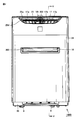
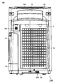
- FIG. 3 is a front view of the air cleaner in the first embodiment. It is a rear view of the air cleaner in Embodiment 1.
- FIG. 3 is a component configuration diagram viewed from the back side of the air cleaner according to the first embodiment.
- FIG. 5 is a cross-sectional view taken along line VV in FIG. 2. It is a top view of the water tank and tank receptacle used for the air cleaner in Embodiment 1. It is a figure which shows the infrared unit in Embodiment 2, and is the elements on larger scale of the area
- FIG. 8 is a cross-sectional view taken along line VIII-VIII in FIG.
- FIG. 8 is a schematic view taken along arrow IX in FIG. 7. It is a front view of the dustproof filter used for the air cleaner in Embodiment 3. 6 is a plan view of a dustproof filter used for an air cleaner in Embodiment 3. FIG. It is a side view of the dustproof filter used for the air cleaner in Embodiment 3. It is a perspective view of the bottom panel used for the air cleaner in Embodiment 4.
- FIG. 14 is a cross-sectional view taken along line XIV-XIV in FIG. 13 and is a cross-sectional view of a region surrounded by XIV in FIG. 5.
- FIG. 10 is a bottom view of the speaker assembly in the fourth embodiment. It is a block diagram which shows schematic structure of the control system of the air cleaner in Embodiment 5.
- FIG. 5 is a front view of the dustproof filter used for the air cleaner in Embodiment 3.
- 6 is a plan view of a dustproof filter used for an air cleaner in Embodiment 3.
- FIGS. 1 to 6 the configuration of air cleaner 1000 in the present embodiment will be described.
- 1 is an overall perspective view of an air cleaner 1000 according to the present embodiment
- FIG. 2 is a front view of the air cleaner 1000 according to the present embodiment
- FIG. 3 is a rear view of the air cleaner 1000 according to the present embodiment.
- FIG. 4 is a component configuration diagram viewed from the back side of the air cleaner 1000 according to the present embodiment
- FIG. 5 is a cross-sectional view taken along line VV in FIG. 2
- FIG. 6 is the present embodiment. It is a top view of the water tank 4 and the tank receptacle 40 which are used for the air cleaner 1000 in FIG.
- the air cleaner 1000 in this Embodiment has the housing 1, the air blower outlet 17 and the air suction inlet 18 are provided in the front side, and the tank receiver 40 in the side surface side. A water supply tank 41 is also provided. An operation panel 100 is provided on the top panel 25 on the upper surface of the housing 1 of the air cleaner 1000.
- the air outlet 17 has a substantially oblong or oval shape that is horizontally long when viewed from the front. When viewed in a plan view, it has a substantially elliptical shape in which the left and right sides recede toward the rear side as it goes to both sides.
- the air outlet 17 is provided with a plurality of vertical wind direction plates 17a and horizontal wind direction plates 17b (positions extending in a substantially horizontal direction) juxtaposed at intervals in the horizontal direction.
- the wind direction plate 17a in the vertical posture is positioned at both end portions in the lateral direction, the plate surface is opened in the laterally outward direction toward the outflow side. As a result, the flow of air blown forward from the air outlet 17 can be expanded in the lateral direction.
- the laterally directed wind direction plate 17b is for making the flow of the air blown forward to a substantially horizontal state.
- the vertical wind direction plate 17a and the horizontal wind direction plate 17b are formed of integrally formed members.
- an infrared unit 200 is provided on the lower surface of the upper wall 171 in the central region. Details of the infrared unit 200 will be described later.
- the air suction port 18 has a substantially rectangular shape when viewed from the front.
- a dustproof filter 300 is detachably attached to the air suction port 18 in a vertical posture. The structure of the dustproof filter 300 will be described later.
- a plurality of wheels 9 with a lock mechanism are attached to the bottom surface of the housing 1. Thereby, after releasing the lock mechanism of the wheel 9 and moving the air purifier 1000 to an appropriate place in the room, the lock mechanism can be operated to install the air purifier without moving on the floor.
- rear panel 2 on the rear surface side of air cleaner 1000 is provided with air inlet 2 a, air outlet 15, dirt detector 150, and voice opening 550.
- the sound opening 550 and the speaker assembly 500 will be described later.
- the inside of the housing 1 is divided forward and backward by a partition wall 11.
- the upper half of the partition wall 11 is inclined backward.
- a filter storage portion 1 a for storing various filters for purification is formed on the rear side of the partition wall 11.
- the filter storage portion 1a is a space that opens to the rear surface side of the housing 1 and is recessed in a rectangular parallelepiped shape.
- the deodorizing filter 7a and the dust collection filter 7b are stored in an overlapped order from the rear side.
- the deodorizing filter 7a has a function of adsorbing odor components such as acetaldehyde, ammonia, and acetic acid in the air.
- the deodorizing filter 7a has a structure in which a non-woven fabric made of polyester is attached to a rectangular frame, activated carbon is uniformly distributed on the frame, and the non-woven fabric made of polyester is covered thereon.
- the dust collection filter 7b has a function of collecting fine dust, and is configured by a so-called HEPA (High Efficiency Particulate Air) filter.
- the HEPA filter is made by combining the aggregate made of polyester and vinylon non-woven fabric with the melt blown non-woven fabric processed with stone, and folding it.
- the antibacterial sheet made of hydroxyapatite-processed non-woven fabric is layered on the upper and lower surfaces of the filter. It has a structure in which a frame made of a nonwoven fabric with melt is welded.
- a detachable rear panel 2 that covers the opening of the filter storage portion 1a is provided.
- the deodorizing filter 7a and the dust collection filter 7b are prevented from falling off from the filter housing portion 1a by the rear panel 2.
- the rear panel 2 has a substantially rectangular plate shape, and air suction ports 2a made up of a plurality of small holes are formed in a matrix shape, and a mesh-like fiber sheet is attached to the back surface.
- the humidification filter unit 3 and the water tank 4 are disposed on the front side of the dust collection filter 7b.
- the water tank 4 is placed on the bottom plate of the housing 1 and can be pulled out together with the humidifying filter unit 3 supported by the water tank 4 from one side (right side in front view) of the housing 1.
- the humidification filter unit 3 has water absorption and air permeability, and includes a disk-shaped water absorption filter 31 folded in a zigzag manner and an annular holding frame 30 for storing and holding the water absorption filter 31.
- the water absorption filter 31 is produced by punching a filter material having an appropriate thickness.
- the holding frame 30 is made of synthetic resin.
- a ring gear 32 is provided on the outer peripheral surface of the holding frame 30, in which teeth are formed over the entire circumference at the center in the width direction.
- the ring gear 32 of the holding frame 30 is meshed with the drive gear 51 of the drive unit 5 disposed above the holding frame 30.
- the drive unit 5 includes a transmission gear meshing with the drive gear 51 and a drive motor (not shown) having an output shaft connected to the transmission gear, and is fixed at an appropriate position in the housing 1.
- two drum-shaped support rollers 6 whose axis is along the width direction of the water tank 4 are arranged in the lower part of the water tank 4 in the longitudinal direction of the water tank 4.
- Each support roller 6 is rotatably supported on both side walls in the width direction of the water tank 4.
- Each support roller 6 is in rolling contact with both side surfaces of the ring gear 32, thereby supporting the holding frame 30 of the humidifying filter unit 3 from below and positioning the water tank 4 in the width direction.
- the humidifying filter unit 3 is supported in such a manner that the lower part is inserted into the water tank 4 and stands vertically.
- the water tank 4 is a dish-shaped container having an open top, and is positioned on the front side of the dust collection filter 7b inside the filter storage portion 1a by being fitted into a guide portion 4g provided on the bottom plate of the housing 1. .
- the water tank 4 can be pulled out from one side surface of the housing 1 by sliding along the guide portion 4g.
- a wide tank receiver 40 is connected to the end of the water tank 4 on the drawer side, and a water supply tank 41 can be attached to and detached from the tank receiver 40.
- the tank receiver 40 is provided with a float switch 400 that detects the water level in the tank receiver.
- the float switch 400 includes a float plate 410 and a support shaft 420.
- a water supply tank 41 is a rectangular parallelepiped container having a water tap 42 at one end, and is attached to the tank receiver 40 in an inverted posture with the water tap 42 side facing downward. .
- the water tap 42 incorporates a constant water level valve.
- the constant water level valve is pushed up by a push-up protrusion 43 (see FIG. 6) standing on the bottom surface of the tank receiver 40 to release the water stored in the water supply tank 41. It has a function of feeding into the water tank 4 and keeping the water level of the stored water inside the water tank 4 constant.
- an air path cover 12 is attached to the front side of the partition wall 11.
- the air path cover 12 includes a lower cylindrical portion 12a and a flat upper rectangular tube portion 12b whose lower end is connected to the outer peripheral portion of the cylindrical portion 12a (however, the partition wall 11 side is open).
- a blower 8 is disposed on the front side of the humidifying filter unit 3 with a partition wall 11 interposed therebetween, and a plurality of vent holes 11 a communicating with the blower 8 are formed in the lower part of the partition wall 11.
- the blower 8 includes a fan 81 and a fan motor 82 that rotationally drives the fan 81.
- the fan 81 is a turbo fan, but a propeller fan or a cross flow fan may also be adopted.
- the fan motor 82 uses a DC motor with emphasis on ease of drive control.
- a blowout air passage 13 is formed in a space located above the blower 8 and surrounded by the partition wall 11 and the rectangular tube portion 12 b of the air passage cover 12.
- the upper surface of the housing 1 is inclined so that the rear side portion is lower than the front side portion, and an air outlet 15 having an upward opening communicating with the blowing air passage 13 is provided on the inclined rear side portion.
- the fan 81 is rotated by driving the fan motor 82 of the blower 8, and external air (indoor air) is sucked from the air suction port 2 a of the rear panel 2.
- the sucked air is deodorized filter 7 a and dust collecting filter 7 b. As it passes through, it is purified to odorless and dust-free air.
- the purified air is humidified by the water absorption filter 31 or is not humidified and is sucked into the center of the fan 81 from the vent 11a of the partition wall 11.
- the air sucked into the center of the fan 81 passes between the fan blades and is discharged from the outer periphery of the fan 81, flows through the blowing air passage 13, is guided upward, and is blown into the room from the air outlet 15.
- the air suction port 18 (see FIGS. 1 and 2) opened to the front surface of the housing 1 has a substantially “U” shape in a cross-sectional view.
- a ventilation path 20 that is curved and extends upward and reaches the air outlet 17 provided at the upper front of the housing 1 is provided.
- the ventilation path 20 is a space surrounded by a rear wall 20a, a front wall 20b, a rear wall 20a, and a side wall 20c connecting edges on both sides of the front wall 20b.
- the rotating shaft 21b is rotatably supported by the side walls 20c on both sides of the ventilation path 20.
- the fan motor 21a for driving the cross flow fan 21 is installed outside the ventilation path 20, and the output shaft of the fan motor 21a is arranged coaxially with the rotating shaft 21b.
- An ion generator 22 that generates positive and negative ions is disposed on the wall surface between the cross flow fan 21 and the air outlet 17 in the ventilation path 20.
- the ion generator 22 is provided with a needle-like discharge electrode (not shown) so as to be exposed in the air path, and an AC waveform or impulse waveform voltage is supplied to the discharge electrode from a power feeding unit (not shown).
- the discharge electrode generates ions.
- the ions generated by the ion generator 22 are added to the air sucked from the air outlet 17 by the cross flow fan 21 and include ions. Air is blown forward from the air outlet 17.
- the air cleaner 1000 is installed on the floor.
- the air (arrow A1) sucked from the back side of the air cleaner 1000 passes through the deodorizing filter 7a and the dust collection filter 7b and is purified.
- the cleaned air is humidified by the humidifying filter unit 3 (may not be humidified).
- the clean air (arrow A2) blown obliquely upward upward from the air outlet 15 on the upper surface circulates in the room through the wall, ceiling, etc., then returns to the front side of the air cleaner 1000, and the front surface of the air cleaner 1000 Hit the side.
- the air (arrow A3) hitting the front side of the air cleaner 1000 is sucked into the air inlet 18 for ions. Dust is removed from the air sucked into the air suction port 18 by the dust filter 300, ions are added when flowing through the ventilation path 20, and the air is blown forward from the air outlet 17 (arrow A4). The air blown forward from the air outlet 17 also circulates and returns to the front side of the air cleaner.
- the dust filter 300 is disposed in the ventilation path 20, but in order to improve the purification capability, a deodorization filter and a dust collection filter similar to the deodorization filter 7a and the dust collection filter 7b may be arranged. .
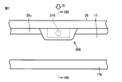
- FIGS. 7 is a partially enlarged view of a region surrounded by VII in FIG. 2
- FIG. 8 is a cross-sectional view taken along line VIII-VIII in FIG. 7
- FIG. 9 is a schematic view taken along arrow IX in FIG. FIG.
- an air outlet 17 defined by a region surrounded by an upper wall 25u and a lower wall 25d (see FIG. 2) is provided on the front side of the housing 1.
- a wind direction plate 17b extending in a substantially horizontal direction is provided between the upper wall 25u and the lower wall 25d.
- An infrared unit 200 including an infrared light receiving element 210 capable of receiving infrared rays is attached to the lower surface of the upper wall 25u.
- an infrared light receiving element 210 is attached on a substrate 230, and the substrate 230 is fixed to a hanging wall 25 a provided on the top panel 25.
- the light receiving part 210a of the infrared light receiving element 210 faces the front side.
- the substrate 230 including the infrared light receiving element 210 is covered with a dustproof hood 220.
- the dust hood 220 is made of a material that can transmit infrared rays.
- the wind direction plate 17b is provided between the upper wall 25u and the lower wall 25d, and has a base material 17b1 extending in a substantially horizontal direction.
- the base material 17b1 is covered with an infrared high scattering member 17b2. ing.
- the high-infrared scattering member 17b2 means a material having a higher degree of irregular reflection than the degree of irregular reflection of the infrared ray that is irradiated from the external device and received by the infrared unit 200.
- irregular reflection means diffuse reflection, and means that light incident on the surface is scattered. Therefore, a high degree of irregular reflection means that the degree of scattering of light incident on the surface is high.
- a heat resistant resin (ABS) is used for the base material 17b1
- a film subjected to nickel plating (electroplating) is used for the infrared high scattering member 17b2.
- the film thickness is 5 microns or less.
- the infrared ray LB1 arriving from the front can be received by the infrared ray receiving element 210 as it is.
- Infrared light LB2 arriving from below can also be received by the infrared light receiving element 210 as it is.
- the infrared ray LB3 arriving from above can be irregularly reflected by the infrared high scattering member 17b2 and received by the infrared light receiving element 210.
- Irradiation angle of the infrared LB3 arriving from above is not constant, but the infrared ray is irregularly reflected by the infrared high scattering member 17b2, so that the infrared ray LB3 diffusely reflected by the infrared high scattering member 17b2 is received by the infrared ray regardless of the irradiation angle of the infrared LB3.
- the element 210 can receive light.
- the infrared unit 200 in the present embodiment can receive light even when irradiated from various angles up and down. Thereby, not only a signal transmitted from the remote control switch of the air cleaner 1000 but also a signal transmitted from, for example, an air conditioner or a self-propelled cleaning robot can be received.
- the air cleaner in the present embodiment it is possible to provide a highly functional air cleaner excellent in light receiving sensitivity without causing such a problem.
- the side surface of the base material 17b1 on the infrared unit 200 side preferably has an inclined surface 171 that extends downward from the rear side toward the front side.
- the air outlet 17 is provided so as to recede toward the both sides from the central region, and therefore, the infrared unit 200. Is provided in the central region of the air outlet 17.
- both sides of the infrared unit 200 are opened.
- the infrared light receiving element 210 can receive infrared rays irradiated from a wider range of angles.
- FIG. 8 shows the case where the entire surface of the base material 17b1 of the wind direction plate 17b is subjected to nickel plating as the infrared high scattering member 17b2, but only the infrared unit 200 side is nickel plated. Processing may be performed. The nickel plating process may be performed only in a range where the infrared unit 200 can receive infrared rays by irregularly reflecting infrared rays.
- the infrared high scattering member 17b2 may be plated with a metal thin film such as chrome plated as well as nickel plated.
- any material may be used as long as the degree of irregular reflection is higher than the degree of irregular reflection of the infrared base material 17b1 irradiated from the external device and received by the infrared unit 200.
- a silver seal or the like may be simply pasted on the base material 17b1.
- the surface may be used as the infrared high scattering member 17b2.
- a chromium vapor deposition process may be used as a film forming method for the infrared high scattering member 17b2.
- the configuration in which the infrared unit 200 is provided on the lower surface of the upper wall 25u as the lower side of the upper wall 25u is described.
- the infrared unit 200 is provided on the upper surface of the lower wall 25d as the lower side of the upper wall 25u. It is also possible to adopt the provided configuration.
- the self-propelled cleaning robot once receives the signal from the air conditioner. It is conceivable to move near the front of the air cleaner 1000 by self-propelling and transmit to the air cleaner 1000.
- a signal from the cleaning robot irradiated from below to the infrared light receiving element 210 can be diffusely reflected by the infrared high scattering member 17b2 on the upper wall 25u and received by the infrared light receiving element 210.
- the infrared light receiving element 210 receives infrared light emitted from the outside.
- the infrared light transmitting element 210 is provided with an infrared light emitting element, and infrared light is transmitted from the infrared unit 200.
- FIG. 10 is a front view of the dustproof filter 300
- FIG. 11 is a plan view of the dustproof filter 300
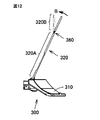
- FIG. 12 is a side view of the dustproof filter 300.
- the dust filter 300 includes a base portion 310 and a filter portion 320 provided so as to stand up from the base portion 310.
- the filter unit 320 includes a filter member 370 and an elastically deformable frame member 330 that holds the filter member 370 so as to surround the filter member 370.
- the frame member 330 is made of an elastically deformable resin material.
- the frame member 330 includes a vertical frame member 330a that stands up from the base portion 310, and a horizontal frame member 330b that extends in a direction intersecting the vertical frame member 330a.
- a fragile region 360 provided in a thin wall is provided.
- the frame member 330 has a horizontal auxiliary frame member 350 that extends in parallel with the horizontal frame member 330b so as to divide the filter member 370 in the vertical direction. Further, in the present embodiment, there is a vertical auxiliary frame member 340 that extends in parallel to the vertical frame member 330a so as to divide the filter member 370 in the left-right direction.
- the longitudinal auxiliary frame member 340 is also provided with a weak region 360.
- the fragile region 360 may be provided in a region in the vicinity of the base portion 310 side (downward side) of the vertical frame member 330a where the horizontal auxiliary frame member 350 intersects.
- the vertical auxiliary frame member 340 may be provided in the vicinity of the base frame 310 side (lower side) of the vertical frame member 330a where the horizontal auxiliary frame member 350 intersects.
- the dustproof filter 300 having the above-described configuration includes a lower filter region 320 ⁇ / b> A located on the base portion 310 side and an upper filter region 320 ⁇ / b> B located on the distal end side, with the fragile region 360 as a boundary. And can be divided into
- the lower filter region 320A and the upper filter region 320B Prior to insertion into the air cleaner 1000, the lower filter region 320A and the upper filter region 320B extend in a straight line. Therefore, since the tip position of the dustproof filter 300 can be easily confirmed, the dustproof filter 300 can be easily inserted into the air suction port 18 of the air cleaner 1000.
- the filter part 320 of the dustproof filter 300 can be easily bent even if a bent part exists in the guide 320G.
- the frame member 330 may be stressed to damage the frame member 330.
- the weak region 360 in the frame member 330, by actively providing the weak region 360 in the frame member 330, even when an external force in the bending direction is applied to the frame member 330 of the dust filter 300, the weak region 360 is bent, Generation of stress on the frame member 330 can be avoided. As a result, the possibility of damaging the frame member 330 can be avoided.
- the fragile region 360 is provided in a region in the vicinity of the base portion 310 side (lower side) of the vertical frame member 330a where the horizontal auxiliary frame member 350 intersects. As a result, the region where the strength is increased by the vertical frame member 330 and the fragile region 360 are adjacent to each other, and the bending in the fragile region 360 can be further promoted.
- FIGS. 13 is a perspective view of the bottom panel 26 used in the air cleaner 1000
- FIG. 14 is a sectional view taken along the line XIV-XIV in FIG. 13
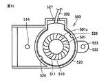
- FIG. 15 is a bottom view of the speaker assembly 500.
- bottom panel 26 used in air cleaner 1000 has a bottom plate 553 that is located on the bottom surface of housing 1, and a rear wall 560 that stands from bottom plate 553 on the rear side of housing 1. ing.
- the rear wall 560 is provided with an audio opening 550 (see FIG. 3).
- the audio opening 550 is provided with a speaker mounting area SP for fixing a speaker assembly 500 (described later) including the speaker 501.
- the speaker mounting area SP includes an inclined bottom 551, a waterproof wall 552, a nut column 554. 555 is provided.
- FIG. 5 has a disc-shaped vibrating portion 501a.
- the speaker assembly 500 includes a first holding member 510 and a second holding member 520.
- the first holding member 510 has a bottomed cylindrical shape, holds the speaker 501 at the bottom, and has a hole 511 that opens the vibration part 501a at the bottom.
- the second holding member 520 also has a bottomed cylindrical shape, accommodates the first holding member 510 from the open side, extends from the bottom toward the open side, and supports the speaker 501 from the back side of the speaker 501.
- a support column 525 is included.
- Locking claws 526 and 526 are provided on the open end side of the cylindrical portion of the second holding member 520. By housing the speaker 501 in the first holding member 510 and further housing the first holding member 510 in the second holding member 520, the locking claws 526 and 526 are engaged with the bottom of the first holding member 510. Thus, the coupled state between the first holding member 510 and the second holding member 520 is maintained.
- the central portion On the back surface of the speaker 501, the central portion is pressed by the support column 525 of the second holding member 520, the speaker 501 is fixed, and the speaker assembly 500 is completed.
- the cable provided in the speaker 501 is pulled out from the notch 527 provided in the second holding member 520.
- the second holding member 520 is provided with a bolt hole 523 provided in the speaker holding flange 522 and a bolt hole 514 provided in the main body of the second holding member 520.
- the bolt holes 523 and 514 are aligned with nut posts 554 and 555 provided on the bottom plate 553, and the speaker assembly 500 is fixed to the speaker mounting region SP using the bolt B1.
- the speaker assembly 500 is fixed to the bottom panel 26 so that the vibrating portion 501a of the speaker 501 faces the bottom plate 553 and has a predetermined gap with respect to the bottom plate 553.
- the bottom plate 553 facing the speaker 501 has an inclined bottom 551 in which the distance from the vibrating portion 501a of the speaker 501 increases as the distance to the rear wall 560 provided with the audio opening 550 is approached.
- the sound emitted from the vibration part 501a can have a sound reverberation effect by being reflected by the inclined bottom 551, and the sound can be directed to the sound opening 550.
- the audio opening 550 on the bottom panel 26 side, but since sound is emitted on the floor side, sound may be attenuated. There is also a risk that foreign matter (water, dust, etc.) from the floor side will easily enter. In the present embodiment, the entry of a foreign object is suppressed by providing an audio opening 550 on the rear side surface. Furthermore, the air cleaner of the present embodiment is often disposed relatively near the wall. In such a case, the sound emitted from the side surface of the rear part is reflected on the wall, and the sound easily reaches the user located on the front side of the air cleaner.
- the waterproof wall 552 is provided so as to surround the speaker assembly 500 in the speaker mounting region SP. Since the water tank 4 is located near the speaker assembly 500, the waterproof wall 552 prevents the speaker assembly 500 from being flooded when water overflows from the water tank 4, and also from the sound opening 550. Prevents water from leaking out.
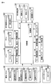
- FIG. 16 is a block diagram showing a schematic configuration of a control system of the air purifier 1000 in the present embodiment.
- the control system of the air purifier 1000 receives an operation panel 100 operated by a user, an operation signal from the operation panel 100, and controls the operation of the fan motor 82, the fan motor 21a, etc., and various physical quantities to the control unit 10. Is configured by a sensor such as the above-described dirt detection unit 150.
- the control unit 10 includes a ROM that stores information such as a program, a CPU that performs input / output control and calculation according to a control program stored in advance in the ROM, a RAM that stores temporarily generated information, a non-volatile write / A readable storage unit 10a and an input / output interface for input / output with an external circuit are provided.
- the dirt detection unit 150, the temperature / humidity sensor 160, and the ion sensor 23 are connected via the input / output interface, and the control unit 10 captures the detection values of these sensors.
- the control unit 10 also takes in the operation control signal input from the infrared light receiving element 210 provided in the infrared unit 200 to the control unit 10 via the input / output interface.
- the control unit 10 is connected with a stop button 121, an air cleaning on button 122, a humidified air cleaning on button 123, an air volume switching button 124, and a voice guide button 125 on the operation panel 100.
- An operation on the operation panel 100 is accepted by the control unit 10.
- the operation of the air cleaner 1000 is accepted by the control unit 10 by operating the stop button 121.
- operation operation information of the air cleaner 1000 is announced using a voice by the speaker 501 provided in the air cleaner 1000.
- the control unit 10 includes a first motor driving circuit 103, a second motor driving circuit 104, a motor driving circuit 105, and a high voltage circuit 106, a fan motor 82 for the fan 81, a fan motor 21a for the fan 21c, and a humidifying filter.
- the drive unit 5 of the unit 3 and the ion generator 22 are connected.
- the control unit 10 outputs a command signal to each of the drive circuits and the high voltage circuit based on the operation signal received from the operation panel 100 and the detected value of each sensor, and the fan motor 82, the fan motor 21a, and the drive unit. 5 and the ion generator 22 is controlled.
- control unit 10 controls the fan motor 82, the fan motor 21a, the drive unit 5, and the ion generator 22 based on the external operation control signal received from the infrared light receiving element 210.
- the external operation control signal includes, for example, an operation control signal transmitted from a remote control switch of the air cleaner 1000, an operation control signal transmitted from an air conditioner, and an operation control signal transmitted from a floor self-propelled cleaning robot. Etc.
Landscapes
- Engineering & Computer Science (AREA)
- Chemical & Material Sciences (AREA)
- Chemical Kinetics & Catalysis (AREA)
- Combustion & Propulsion (AREA)
- Mechanical Engineering (AREA)
- General Engineering & Computer Science (AREA)
- Computer Networks & Wireless Communication (AREA)
- Filtering Of Dispersed Particles In Gases (AREA)
- Disinfection, Sterilisation Or Deodorisation Of Air (AREA)
Abstract
Description
図1から図6を参照して、本実施の形態における空気清浄機1000の構成について説明する。図1は、本実施の形態における空気清浄機1000の全体斜視図、図2は、本実施の形態における空気清浄機1000の正面図、図3は、本実施の形態における空気清浄機1000の背面図、図4は、本実施の形態における空気清浄機1000の背面側から見た部品構成図、図5は、図2中のV-V線矢視断面図、図6は、本実施の形態における空気清浄機1000に用いられる水槽4およびタンク受け40の平面図である。
次に、図5を参照して、上記構成の空気清浄機1000による空気の流れについて説明する。空気清浄機1000は床面に設置されている。空気清浄機1000の背面側から吸引された空気(矢印A1)は、脱臭フィルタ7aおよび集塵フィルタ7bを通過し、清浄化される。清浄化された空気は、加湿フィルタユニット3により加湿される(加湿されない場合もある)。
次に、図7から図9を参照して、本実施の形態における赤外線ユニット200について説明する。図7は、図2中のVIIで囲まれた領域の部分拡大図、図8は、図7中のVIII-VIII線矢視断面図、図9は、図7中のIX矢視での模式図である。
次に、図10から図12を参照して、本実施の形態における防塵フィルタ300について説明する。図10は、防塵フィルタ300の正面図、図11は、防塵フィルタ300の平面図、図12は、防塵フィルタ300の側面図である。
次に、図13から図15を参照して、本実施の形態におけるスピーカ組立体500について説明する。図13は、空気清浄機1000に用いられる底面パネル26の斜視図、図14は、図13中のXIV-XIV線断面図、図15は、スピーカ組立体500の底面図である。
次に、図16を参照して、本実施の形態における空気清浄機1000の制御系統について説明する。図16は、本実施の形態における空気清浄機1000の制御系統の概略構成を示すブロック図である。空気清浄機1000の制御系統は、ユーザが操作する操作パネル100、操作パネル100からの操作信号を受け付け、ファンモータ82およびファンモータ21a等の動作を制御する制御部10、制御部10へ各種物理量を入力する上述の汚れ検出部150等のセンサなどにより構成されている。
Claims (5)
- ハウジングの前側に、上部壁および下部壁によって取り囲まれる領域によって規定される空気吹出口を有する空気清浄機であって、
前記上部壁と前記下部壁との間に設けられ、略水平方向に延びる風向板と、
前記上部壁の下方に設けられ、赤外線の受信および/または送信が可能な赤外線素子を含む赤外線ユニットと、を備え、
前記風向板は、
前記上部壁と前記下部壁との間に設けられ、略水平方向に延びる基材と、
前記基材の前記赤外線ユニット側に設けられ、前記赤外線ユニットに受信される赤外線および/または前記赤外線ユニットから送信される赤外線の前記基材に対する乱反射の度合いよりも乱反射の度合いが高い赤外線高散乱部材と、を含む空気清浄機。 - 前記基材の前記赤外線ユニット側の側面は、後側から前側に向かうにしたがって下方にむかう傾斜面を有する、請求項1に記載の空気清浄機。
- 前記赤外線高反射部材は、前記基材に対してメッキ処理が施された膜である、請求項1または2に記載の空気清浄機。
- 前記空気清浄機を平面視した場合に、前記空気吹出口は、中央領域から両側に向かうしたがって後側に後退するように設けられ、
前記赤外線ユニットは、前記空気吹出口の前記中央領域に設けられている、請求項1から3のいずれか1項に記載の空気清浄機。 - 前記赤外線素子は、その受光部が前側を向くように配置されている、請求項1から4のいずれか1項に記載の空気清浄機。
Priority Applications (2)
| Application Number | Priority Date | Filing Date | Title |
|---|---|---|---|
| US14/909,779 US9415341B2 (en) | 2013-08-23 | 2014-02-25 | Air purifier |
| CN201480045496.2A CN105492835B (zh) | 2013-08-23 | 2014-02-25 | 空气清洁器 |
Applications Claiming Priority (2)
| Application Number | Priority Date | Filing Date | Title |
|---|---|---|---|
| JP2013-173211 | 2013-08-23 | ||
| JP2013173211A JP6076858B2 (ja) | 2013-08-23 | 2013-08-23 | 空気清浄機 |
Publications (1)
| Publication Number | Publication Date |
|---|---|
| WO2015025539A1 true WO2015025539A1 (ja) | 2015-02-26 |
Family
ID=52483330
Family Applications (1)
| Application Number | Title | Priority Date | Filing Date |
|---|---|---|---|
| PCT/JP2014/054531 Ceased WO2015025539A1 (ja) | 2013-08-23 | 2014-02-25 | 空気清浄機 |
Country Status (4)
| Country | Link |
|---|---|
| US (1) | US9415341B2 (ja) |
| JP (1) | JP6076858B2 (ja) |
| CN (1) | CN105492835B (ja) |
| WO (1) | WO2015025539A1 (ja) |
Cited By (3)
| Publication number | Priority date | Publication date | Assignee | Title |
|---|---|---|---|---|
| US20170122604A1 (en) * | 2015-10-28 | 2017-05-04 | Jinhua City Xin'an Electric Co., Ltd | Constant temperature and humidity machine |
| WO2017156993A1 (zh) * | 2016-03-15 | 2017-09-21 | 大连理工大学 | 一种利用热分解法去除室内污染的多功能空气净化装置 |
| US10385867B2 (en) | 2016-07-19 | 2019-08-20 | Jinhua City Xin'an Electric Co., Ltd. | Multi-directional cooling fan |
Families Citing this family (12)
| Publication number | Priority date | Publication date | Assignee | Title |
|---|---|---|---|---|
| US9861778B2 (en) * | 2013-03-15 | 2018-01-09 | Resmed Limited | Humidifier reservoir |
| JP2017110875A (ja) * | 2015-12-18 | 2017-06-22 | パナソニックIpマネジメント株式会社 | 加湿装置 |
| US20180142917A1 (en) * | 2016-11-18 | 2018-05-24 | Yao-Tsung Kao | Air Conditioner Circulation Apparatus with Environmental Protection and High Efficiency |
| US11541342B2 (en) | 2018-03-07 | 2023-01-03 | Lg Electronics Inc. | Indoor unit for air conditioner |
| TWI813745B (zh) * | 2018-09-25 | 2023-09-01 | 日商夏普股份有限公司 | 空氣清淨機及空氣清淨機的控制方法 |
| US10837661B2 (en) | 2018-10-02 | 2020-11-17 | Carl Samuel, Jr. | Air purifying device |
| US11524089B2 (en) * | 2018-10-11 | 2022-12-13 | Dongguan Yih Teh Electric Products Co., Ltd. | Hand wash cleaning and environmental purification diffuser |
| JP7252867B2 (ja) * | 2019-09-13 | 2023-04-05 | シャープ株式会社 | 空気調和機 |
| KR102786746B1 (ko) * | 2020-02-11 | 2025-03-27 | 삼성전자주식회사 | 가습장치 |
| JPWO2022025180A1 (ja) * | 2020-07-30 | 2022-02-03 | ||
| US11344649B1 (en) | 2020-11-12 | 2022-05-31 | Khanh Ngoc Tran | Modular contaminate capture and sterilization apparatus and method |
| JP1715423S (ja) * | 2021-09-08 | 2022-05-19 | 空気清浄機 |
Citations (3)
| Publication number | Priority date | Publication date | Assignee | Title |
|---|---|---|---|---|
| JP2004069150A (ja) * | 2002-08-06 | 2004-03-04 | Sanyo Electric Co Ltd | 空気清浄機 |
| JP2005076988A (ja) * | 2003-09-01 | 2005-03-24 | Matsushita Electric Ind Co Ltd | 輻射暖房装置を有する空気調和機 |
| JP2011017490A (ja) * | 2009-07-09 | 2011-01-27 | Panasonic Corp | 空気調和機 |
Family Cites Families (14)
| Publication number | Priority date | Publication date | Assignee | Title |
|---|---|---|---|---|
| JPH06147980A (ja) * | 1992-10-30 | 1994-05-27 | Sanyo Electric Co Ltd | 輻射センサー |
| JPH09122421A (ja) | 1995-10-30 | 1997-05-13 | Matsushita Seiko Co Ltd | 空気用フィルターおよびその応用機器 |
| CN1258662C (zh) * | 2000-10-04 | 2006-06-07 | 夏普公司 | 空调机及温度检测装置 |
| CN2729568Y (zh) * | 2004-07-05 | 2005-09-28 | 裴立凡 | 用于空调机节电的红外遥控指令转发器 |
| US20070009363A1 (en) * | 2005-07-08 | 2007-01-11 | King Paulmicheal L | Ceiling fan air purification system |
| ES2324365T3 (es) * | 2005-10-11 | 2009-08-05 | Fujitsu General Limited | Aparato de aire acondicionado. |
| JP2007208981A (ja) | 2007-01-30 | 2007-08-16 | Clever Planning:Kk | 赤外線発光装置 |
| CN201203947Y (zh) * | 2007-11-23 | 2009-03-04 | 深圳Tcl新技术有限公司 | 一种提高遥控接收灵敏度的装置 |
| JP5808996B2 (ja) | 2011-09-27 | 2015-11-10 | シャープ株式会社 | 空気清浄機及び空気清浄機の使用方法 |
| JP5800652B2 (ja) | 2011-09-27 | 2015-10-28 | シャープ株式会社 | 空気清浄機 |
| JP5645788B2 (ja) * | 2011-09-27 | 2014-12-24 | シャープ株式会社 | 空気清浄機 |
| JP2013078719A (ja) | 2011-10-03 | 2013-05-02 | Sharp Corp | 空気清浄機 |
| US20130081541A1 (en) * | 2011-10-03 | 2013-04-04 | Erik John Hasenoehrl | Air freshening network |
| JP5261610B2 (ja) | 2012-12-28 | 2013-08-14 | シャープ株式会社 | 加湿装置及び空気清浄機 |
-
2013
- 2013-08-23 JP JP2013173211A patent/JP6076858B2/ja not_active Expired - Fee Related
-
2014
- 2014-02-25 WO PCT/JP2014/054531 patent/WO2015025539A1/ja not_active Ceased
- 2014-02-25 US US14/909,779 patent/US9415341B2/en not_active Expired - Fee Related
- 2014-02-25 CN CN201480045496.2A patent/CN105492835B/zh not_active Expired - Fee Related
Patent Citations (3)
| Publication number | Priority date | Publication date | Assignee | Title |
|---|---|---|---|---|
| JP2004069150A (ja) * | 2002-08-06 | 2004-03-04 | Sanyo Electric Co Ltd | 空気清浄機 |
| JP2005076988A (ja) * | 2003-09-01 | 2005-03-24 | Matsushita Electric Ind Co Ltd | 輻射暖房装置を有する空気調和機 |
| JP2011017490A (ja) * | 2009-07-09 | 2011-01-27 | Panasonic Corp | 空気調和機 |
Cited By (3)
| Publication number | Priority date | Publication date | Assignee | Title |
|---|---|---|---|---|
| US20170122604A1 (en) * | 2015-10-28 | 2017-05-04 | Jinhua City Xin'an Electric Co., Ltd | Constant temperature and humidity machine |
| WO2017156993A1 (zh) * | 2016-03-15 | 2017-09-21 | 大连理工大学 | 一种利用热分解法去除室内污染的多功能空气净化装置 |
| US10385867B2 (en) | 2016-07-19 | 2019-08-20 | Jinhua City Xin'an Electric Co., Ltd. | Multi-directional cooling fan |
Also Published As
| Publication number | Publication date |
|---|---|
| US9415341B2 (en) | 2016-08-16 |
| JP2015040675A (ja) | 2015-03-02 |
| CN105492835A (zh) | 2016-04-13 |
| CN105492835B (zh) | 2018-01-30 |
| US20160175755A1 (en) | 2016-06-23 |
| JP6076858B2 (ja) | 2017-02-08 |
Similar Documents
| Publication | Publication Date | Title |
|---|---|---|
| JP6076858B2 (ja) | 空気清浄機 | |
| JP4808201B2 (ja) | 加湿装置及び空気清浄機 | |
| JP4011094B1 (ja) | 空気清浄機 | |
| CN103764177B (zh) | 空气清洁器和空气清洁器的使用方法 | |
| JP6353561B2 (ja) | 空気清浄機 | |
| WO2008015851A1 (fr) | Épurateur d'air | |
| JP5808996B2 (ja) | 空気清浄機及び空気清浄機の使用方法 | |
| JP5980637B2 (ja) | 空気調和機 | |
| CN202915485U (zh) | 空气净化机 | |
| JP6225225B2 (ja) | 空気調和機 | |
| JP2018167147A (ja) | 吸着ユニット及び空気清浄機 | |
| JP4368367B2 (ja) | 空気清浄機 | |
| JP2016137488A (ja) | 送風装置 | |
| JP4630245B2 (ja) | 加湿装置 | |
| JP2012154556A (ja) | 空気調和機 | |
| CN206648190U (zh) | 一种具有有毒气体报警功能的空气净化器 | |
| JP2016020781A (ja) | 電気機器 | |
| JP6105899B2 (ja) | 加湿装置 | |
| JP2013078718A (ja) | 送風装置 | |
| CN203837212U (zh) | 空气清洁器 | |
| JP6137799B2 (ja) | 送風装置 | |
| JP2004060947A (ja) | 空気調和機 | |
| JP2004060937A (ja) | 空気清浄機 | |
| JP2014074505A (ja) | 送風装置 | |
| JP2016013455A (ja) | 空気清浄機及び空気清浄機の使用方法 |
Legal Events
| Date | Code | Title | Description |
|---|---|---|---|
| WWE | Wipo information: entry into national phase |
Ref document number: 201480045496.2 Country of ref document: CN |
|
| 121 | Ep: the epo has been informed by wipo that ep was designated in this application |
Ref document number: 14838469 Country of ref document: EP Kind code of ref document: A1 |
|
| WWE | Wipo information: entry into national phase |
Ref document number: 14909779 Country of ref document: US |
|
| NENP | Non-entry into the national phase |
Ref country code: DE |
|
| 122 | Ep: pct application non-entry in european phase |
Ref document number: 14838469 Country of ref document: EP Kind code of ref document: A1 |