WO2015020168A1 - 動力伝達装置 - Google Patents
動力伝達装置 Download PDFInfo
- Publication number
- WO2015020168A1 WO2015020168A1 PCT/JP2014/070935 JP2014070935W WO2015020168A1 WO 2015020168 A1 WO2015020168 A1 WO 2015020168A1 JP 2014070935 W JP2014070935 W JP 2014070935W WO 2015020168 A1 WO2015020168 A1 WO 2015020168A1
- Authority
- WO
- WIPO (PCT)
- Prior art keywords
- gear member
- members
- planetary gear
- carrier
- sun gear
- Prior art date
- Legal status (The legal status is an assumption and is not a legal conclusion. Google has not performed a legal analysis and makes no representation as to the accuracy of the status listed.)
- Ceased
Links
Images


Classifications
-
- F—MECHANICAL ENGINEERING; LIGHTING; HEATING; WEAPONS; BLASTING
- F16—ENGINEERING ELEMENTS AND UNITS; GENERAL MEASURES FOR PRODUCING AND MAINTAINING EFFECTIVE FUNCTIONING OF MACHINES OR INSTALLATIONS; THERMAL INSULATION IN GENERAL
- F16D—COUPLINGS FOR TRANSMITTING ROTATION; CLUTCHES; BRAKES
- F16D55/00—Brakes with substantially-radial braking surfaces pressed together in axial direction, e.g. disc brakes
- F16D55/02—Brakes with substantially-radial braking surfaces pressed together in axial direction, e.g. disc brakes with axially-movable discs or pads pressed against axially-located rotating members
- F16D55/04—Brakes with substantially-radial braking surfaces pressed together in axial direction, e.g. disc brakes with axially-movable discs or pads pressed against axially-located rotating members by moving discs or pads away from one another against radial walls of drums or cylinders
- F16D55/14—Brakes with substantially-radial braking surfaces pressed together in axial direction, e.g. disc brakes with axially-movable discs or pads pressed against axially-located rotating members by moving discs or pads away from one another against radial walls of drums or cylinders with self-tightening action, e.g. by means of coacting helical surfaces or balls and inclined surfaces
-
- F—MECHANICAL ENGINEERING; LIGHTING; HEATING; WEAPONS; BLASTING
- F16—ENGINEERING ELEMENTS AND UNITS; GENERAL MEASURES FOR PRODUCING AND MAINTAINING EFFECTIVE FUNCTIONING OF MACHINES OR INSTALLATIONS; THERMAL INSULATION IN GENERAL
- F16D—COUPLINGS FOR TRANSMITTING ROTATION; CLUTCHES; BRAKES
- F16D51/00—Brakes with outwardly-movable braking members co-operating with the inner surface of a drum or the like
-
- F—MECHANICAL ENGINEERING; LIGHTING; HEATING; WEAPONS; BLASTING
- F16—ENGINEERING ELEMENTS AND UNITS; GENERAL MEASURES FOR PRODUCING AND MAINTAINING EFFECTIVE FUNCTIONING OF MACHINES OR INSTALLATIONS; THERMAL INSULATION IN GENERAL
- F16D—COUPLINGS FOR TRANSMITTING ROTATION; CLUTCHES; BRAKES
- F16D65/00—Parts or details
- F16D65/14—Actuating mechanisms for brakes; Means for initiating operation at a predetermined position
- F16D65/16—Actuating mechanisms for brakes; Means for initiating operation at a predetermined position arranged in or on the brake
- F16D65/22—Actuating mechanisms for brakes; Means for initiating operation at a predetermined position arranged in or on the brake adapted for pressing members apart, e.g. for drum brakes
-
- F—MECHANICAL ENGINEERING; LIGHTING; HEATING; WEAPONS; BLASTING
- F16—ENGINEERING ELEMENTS AND UNITS; GENERAL MEASURES FOR PRODUCING AND MAINTAINING EFFECTIVE FUNCTIONING OF MACHINES OR INSTALLATIONS; THERMAL INSULATION IN GENERAL
- F16D—COUPLINGS FOR TRANSMITTING ROTATION; CLUTCHES; BRAKES
- F16D2121/00—Type of actuator operation force
- F16D2121/18—Electric or magnetic
- F16D2121/20—Electric or magnetic using electromagnets
-
- F—MECHANICAL ENGINEERING; LIGHTING; HEATING; WEAPONS; BLASTING
- F16—ENGINEERING ELEMENTS AND UNITS; GENERAL MEASURES FOR PRODUCING AND MAINTAINING EFFECTIVE FUNCTIONING OF MACHINES OR INSTALLATIONS; THERMAL INSULATION IN GENERAL
- F16D—COUPLINGS FOR TRANSMITTING ROTATION; CLUTCHES; BRAKES
- F16D2125/00—Components of actuators
- F16D2125/18—Mechanical mechanisms
- F16D2125/20—Mechanical mechanisms converting rotation to linear movement or vice versa
- F16D2125/34—Mechanical mechanisms converting rotation to linear movement or vice versa acting in the direction of the axis of rotation
- F16D2125/36—Helical cams, Ball-rotating ramps
-
- F—MECHANICAL ENGINEERING; LIGHTING; HEATING; WEAPONS; BLASTING
- F16—ENGINEERING ELEMENTS AND UNITS; GENERAL MEASURES FOR PRODUCING AND MAINTAINING EFFECTIVE FUNCTIONING OF MACHINES OR INSTALLATIONS; THERMAL INSULATION IN GENERAL
- F16D—COUPLINGS FOR TRANSMITTING ROTATION; CLUTCHES; BRAKES
- F16D2125/00—Components of actuators
- F16D2125/18—Mechanical mechanisms
- F16D2125/44—Mechanical mechanisms transmitting rotation
- F16D2125/46—Rotating members in mutual engagement
- F16D2125/50—Rotating members in mutual engagement with parallel non-stationary axes, e.g. planetary gearing
-
- F—MECHANICAL ENGINEERING; LIGHTING; HEATING; WEAPONS; BLASTING
- F16—ENGINEERING ELEMENTS AND UNITS; GENERAL MEASURES FOR PRODUCING AND MAINTAINING EFFECTIVE FUNCTIONING OF MACHINES OR INSTALLATIONS; THERMAL INSULATION IN GENERAL
- F16D—COUPLINGS FOR TRANSMITTING ROTATION; CLUTCHES; BRAKES
- F16D2127/00—Auxiliary mechanisms
- F16D2127/08—Self-amplifying or de-amplifying mechanisms
Definitions
- the present invention relates to a power transmission device, and more particularly to a power transmission device including a planetary gear mechanism.
- a power transmission device As a power transmission device, a power transmission device including a planetary gear mechanism is used in order to change a power transmission path or to block power transmission.
- a power transmission device including a gear mechanism is used in order to change a power transmission path or to block power transmission.
- Patent Document 1 in a hybrid vehicle that transmits the driving force of an internal combustion engine to a generator and driving wheels and drives the driving wheels while supplying electric power generated by the generator to the electric motor, The use of a power transmission device including a gear mechanism is described.
- the planetary gear member meshes with the sun gear member and the internal gear member, and can be revolved around the rotation axis and supported by the carrier member so as to be able to rotate around the rotation axis.
- the sun gear member, the internal gear member, the planetary gear member, and the carrier member rotate relative to each other.
- the present invention has been made in view of the above-described problems in a conventional power transmission device including a planetary gear mechanism, and a main object of the present invention is to provide a power transmission device that is smaller than the conventional one. It is to be.
- the main problems described above include a sun gear member and an internal gear member that rotate relatively around the rotation axis, a planetary gear member that meshes with the sun gear member and the internal gear member, and a rotation axis.
- a planetary gear member rotatably supported about a parallel axis of rotation and a carrier member rotating about the axis of rotation, one of the sun gear member, the internal gear member and the carrier member, and the other one of which
- the first and second rotating members are configured to be connected to each other, and the first and second rotating members are prevented from relative rotation of the three gear members and the carrier member.
- the two members constituting the first pair of members are relatively moved along the rotation axis, and the two members are frictionally engaged with each other on the corresponding side surface so that the relative rotation is performed. Be blocked.
- two members constituting the second member pair among the sun gear member, the internal gear member, the planetary gear member, and the carrier member are relatively moved along the rotation axis, and the two members correspond to each other. Relative engagement is prevented by frictional engagement at the side. In other words, a frictional force is generated by frictional engagement of two members in each of the first and second member pairs, and relative rotation of the members is prevented by these frictional forces.
- the “member pair” means a combination of two members among a sun gear member, an internal gear member, a planetary gear member, and a carrier member. Further, the two members constituting the first member pair and the two members constituting the second member pair may be different from each other and may include one common member.
- the two members of the first member pair are a sun gear member and a planetary gear member
- the two members of the second member pair are a planetary gear member.
- And may be a carrier member.
- the frictional force is generated by the frictional engagement of the sun gear member and the planetary gear member on the corresponding side surface, and the planetary gear member and the carrier member are frictionally engaged on the corresponding side surface.
- a frictional force is generated by combining. Therefore, compared with the case where only the sun gear member and the planetary gear member are frictionally engaged, or the case where only the planetary gear member and the carrier member are frictionally engaged, the number of friction engagement portions is increased and a high frictional force is obtained. Can be generated.
- the planetary gear member is one common member constituting the first and second member pairs, and revolves around the rotation axis with respect to the sun gear member and rotates around an axis parallel to the rotation axis. To do. Therefore, a high frictional force can be generated by frictional engagement by both revolution and rotation without increasing the pressing force for frictional engagement of these members.
- the two members of the first member pair are an internal gear member and a planetary gear member
- the two members of the second member pair are a planetary gear member.
- And may be a carrier member.
- the internal gear member and the planetary gear member are frictionally engaged with each other on the corresponding side surface to generate a frictional force, and the planetary gear member and the carrier member are frictionally engaged on the corresponding side surface.
- a frictional force is generated by combining. Therefore, compared with the case where only the internal gear member and the planetary gear member are frictionally engaged, or the case where only the planetary gear member and the carrier member are frictionally engaged, the number of friction engagement portions is increased and a high frictional force is obtained. Can be generated.
- the planetary gear member is one common member constituting the first and second member pairs. Therefore, a high frictional force can be generated by frictional engagement by both revolution and rotation without increasing the pressing force for frictional engagement of these members.
- the two members of the first member pair are an internal gear member and a planetary gear member
- the two members of the second member pair are a sun gear member.
- an internal gear member is an internal gear member.
- the internal gear member and the planetary gear member are frictionally engaged with each other on the corresponding side surface, thereby generating a frictional force, and the sun gear member and the internal gear member are frictionally generated on the corresponding side surface.
- a frictional force is generated by the engagement. Therefore, when only the internal gear member and the planetary gear member are frictionally engaged, or when only the sun gear member and the internal gear member are frictionally engaged, the number of friction engagement portions is increased and the friction force is increased. Can be generated.
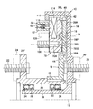
- FIG. 1 is a partial cross-sectional view showing a power transmission device 10 according to a first embodiment of the present invention cut along a cut surface passing through a rotation axis, and FIG. It is the partial front view seen from the direction. 1 is a cross-sectional view taken along the line II of FIG.
- the power transmission device 10 includes a sun gear member 14 and an internal gear member 16 that rotate relatively around a rotation axis 12, and four planetary gear members 18 that mesh with the sun gear member 14 and the internal gear member 16. And a carrier member 78.
- the carrier member 78 rotates around the rotational axis 12 together with the planetary gear member 18 while maintaining the four planetary gear members 18 equally spaced around the rotational axis 12.
- the sun gear member 14 has an annular plate-like portion 14D that extends perpendicularly to the rotation axis 12 and around the rotation axis, and a base portion 14B that is integral with the inner peripheral portion of the annular plate-like portion.
- An outer hollow rotator 20 extending along the rotation axis 12 is disposed on the radially inner side of the base portion 14B.
- Key grooves extending along the rotation axis 12 are provided on the inner peripheral surface of the base portion 14B and the outer surface of the outer hollow rotating body 20 that is radially opposed to the base portion 14B, and the keys 22 are fitted into these key grooves. It is.
- the sun gear member 14 can rotate about the rotation axis 12 integrally with the outer hollow rotator 20 and can move along the rotation axis 12 with respect to the outer hollow rotator 20.
- the outer hollow rotator 20 is provided with a flange 20F extending around the rotation axis perpendicular to the rotation axis 12.
- An input rotation member 24 as a first rotation member that rotates around the rotation axis 12 is connected to the flange 20F by a plurality of bolts 22 that are evenly spaced around the rotation axis 12.
- the flange 20F is formed integrally with the outer hollow rotator 20, but the flange 20F is formed separately from the outer hollow rotator 20, and the outer hollow rotator is connected by a connecting means such as a bolt. 20 may be integrally connected.
- the internal gear member 16 includes a disk portion 16A extending perpendicularly to the rotation axis 12 and around the rotation axis, and a cylindrical portion 16B integrally connected to the outer periphery of the disk portion and extending along the rotation axis 12.
- the inner peripheral portion of the disk portion 16A is integrally connected to the inner hollow rotator 26, and the inner hollow rotator 26 extends along the rotation axis 12 on the radially inner side of the outer hollow rotator 20.
- the disk portion 16A has a second bolt that rotates around the rotation axis 12 by four bolts 28 spaced by 90 ° from each other around the rotation axis 12 and a nut not shown in FIG.
- An output rotating member 30 as a rotating member is connected.
- a pair of ball bearings 32 that are spaced apart from each other along the rotational axis 12 are disposed.
- a space between the pair of ball bearings 32, the outer hollow rotator 20, and the inner hollow rotator 26 is filled with a lubricant such as grease.
- a pair of seal members 34 are arranged on both sides in the axial direction with respect to the pair of ball bearings 32, and the seal member 34 prevents the dust and muddy water from entering the ball bearing 32 and the inner hollow rotator 20 and the inner hollow rotator 26. It is sealed between.
- the four planetary gear members 18 and the carrier member 78 are disposed between the annular plate-like portion 14D of the sun gear member 14 and the disk portion 16A of the internal gear member 16.
- the planetary gear member 18 is adjacent to the annular plate portion 14D
- the carrier member 78 is adjacent to the disk portion 16A
- the planetary gear member 18 and the carrier member 78 are adjacent to each other.
- Each planetary gear member 18 has a substantially disk shape extending around the axis 36 perpendicular to the axis 36 parallel to the rotation axis 12.
- the carrier member 78 has an annular plate shape that extends perpendicularly to the rotation axis 12 and around the rotation axis 12, and extends along the axis 36 on the side facing the planetary gear member 18. It has a cylindrical recess 78A.
- Each planetary gear member 18 has a cylindrical protrusion 18P that protrudes along the axis 36, and the protrusion 18P fits into the recess 78A so that the carrier member 78 is rotatably supported around the axis 36. .
- Each planetary gear member 18 has a friction portion 38L on the side surface on the annular plate-like portion 14D side, and has a friction surface 18S on the side surface on the carrier member 78 side.
- the friction portion 38L extends in an annular shape around the axis 36 in a state of being raised from the side surface of the disk-shaped main body of the planetary gear member.
- the planetary gear member 18 is manufactured by, for example, a powder sintering method, so that the friction portion may be formed integrally with the disc-shaped main body.
- the friction portion may be formed by attaching an annular belt-like friction material to the side surface of the main body by bonding or other means.
- the carrier member 78 has a friction surface 78SO that can be frictionally engaged with the friction surface 16S of the disk portion 16A on the side surface facing the disk portion 16A of the internal gear member 16, and the friction surface 18S on the side facing the planetary gear member 18. And a friction surface 78SI capable of friction engagement.
- the inner surface of the annular plate-like portion 14D of the sun gear member 14 has a friction surface 14S that can be frictionally engaged with the friction portion 38L of the planetary gear member 18, and the outer surface of the annular plate-like portion 14D is smooth.
- Each planetary gear member 18 has a spur gear 40 on the outer periphery.
- the external gear 40 meshes with a spur gear internal gear 42 formed on the inner surface of the cylindrical portion 16B of the internal gear member 16 on the radially outer side, and is formed on the outer surface of the base portion 14B of the sun gear member 14 on the radially inner side. Meshed with a spur external gear 44. Therefore, when the sun gear member 14 rotates around the rotation axis 12, each planetary gear member 18 revolves around the rotation axis 12 with respect to the sun gear member 14 and the internal gear member 16 while rotating around the axis 36. .
- the internal gear member 16 rotates around the rotation axis 12 in the direction opposite to the sun gear member 14 with respect to the sun gear member 14, and the carrier member 78 together with the four planetary gear members 18 has the rotation axis 12.
- the sun gear member 14 and the internal gear member 16 rotate around.
- the annular plate-like portion 14D of the sun gear member 14 has an annular groove 46 that extends around the rotation axis 12 over the entire circumference and opens radially outward.
- a solenoid 48 is disposed in the annular groove 46, and the solenoid 48 extends annularly around the rotation axis 12.
- the sun gear member 14 is provided with energization devices 50 and 52 that are spaced apart from each other in the radial direction at a position radially inward of the annular groove 46.
- the sun gear member 14 and the internal gear member 16 are made of a paramagnetic metal material.
- the planetary gear member 18 and the carrier member 78 may be formed of either a metal material having paramagnetism or a metal material not having paramagnetism.
- the energization devices 50 and 52 include cylinder holes 54 and 56 extending along the rotation axis 12, and cylindrical pistons 58 and 60 that fit into the cylinder holes, Compression coil springs 64 and 66 for biasing these pistons toward the stationary member 62 are provided.
- the pistons 58 and 60 are formed of a conductor, but the cylindrical outer peripheral surface is coated with an electrical insulating material.
- Conductors 68 and 70 are fixed to portions of the stationary member 62 facing the energization devices 50 and 52, respectively.
- the conductors 68 and 70 are electrically insulated by an electrical insulating material 72 except for the portions facing the corresponding pistons 58 and 60.
- the conductors 68 and 70 and the electrical insulating material 72 extend annularly around the rotation axis 12.
- the outer ends of the pistons 58 and 60 are in contact with the conductors 68 and 70 so as to be energized, respectively, and the inner ends of these pistons are connected to the solenoid 48 by conducting wires 74 and 76, respectively.
- the energization to the solenoid 48 performed through the energization devices 50 and 52 is controlled by an electronic control device not shown in the drawing.
- the solenoid 48 When the control current is not supplied to the solenoid 48, the solenoid does not generate an electromagnetic attraction force to the disk portion 16A. Therefore, the annular plate-like portion 14D of the sun gear member 14 causes the planetary gear member 18 to move to the disk portion 16A. Do not press against. Therefore, although the sun gear member 14, the internal gear member 16, and the planetary gear member 18 rotate relative to each other as gear members constituting the planetary gear mechanism, their friction surfaces do not frictionally engage. Therefore, since the frictional force due to the frictional engagement is not generated, the action of decelerating and stopping the relative rotational movement of each member does not occur.
- the internal gear member 16 rotates in the reverse direction around the rotation axis 12 with respect to the sun gear member 14 and the outer hollow rotator 20, and the planetary gear member 18 rotates relative to the internal gear member 16 and the sun gear member 14. Revolves around the axis 36 while revolving around. Therefore, the rotational motion of the input rotating member 24 is shifted at a gear ratio determined by the gear ratio of each gear member and transmitted to the output rotating member 30, and the rotational torque of the input rotating member 24 is the reciprocal of the gear ratio. Is transmitted to the output rotating member 30 at a torque transmission ratio of.
- the solenoid 48 when a control current is supplied to the solenoid 48, the solenoid generates an electromagnetic attractive force to the disk portion 16A.
- the attracting force of the solenoid 48 presses the annular plate-like portion 14D of the sun gear member 14 against the planetary gear member 18, and presses the planetary gear member 18 and the carrier member 78 against the disk portion 16A of the internal gear member 16.
- the friction surface 14S of the annular plate-shaped portion 14D, the friction portion 38L of the planetary gear member 18, the friction surface 18S of the planetary gear member 18, the friction surface 78SI of the carrier member 78, the friction surface 78SO of the carrier member 78, and the disk portion 16A. are frictionally engaged with each other.
- Each of these friction engagement portions generates a frictional force, and the frictional force increases as the electromagnetic attractive force of the solenoid 48 increases.
- the sun gear member 14, the internal gear member 16, the planetary gear member 18, and the carrier member 78 do not rotate relatively and rotate integrally around the rotation axis 12. Therefore, the input rotation member 24 and the output rotation member 30 are directly connected.
- the sun gear member 14, the planetary gear member 18 and the carrier member 78 are moved relative to the internal gear member 16 along the rotation axis 12.
- the member pair of the sun gear member 14 and the planetary gear member 18, the member pair of the planetary gear member 18 and the carrier member 78, and the member pair of the carrier member 78 and the internal gear member 16 there are two members respectively. Friction engagement is performed on the side surface. Therefore, since a high frictional force is generated by the three friction engagement portions of the three member pairs, a higher braking force can be generated as compared with the conventional power transmission device. Therefore, the rotation of each member can be effectively braked, and the relative rotation of the three gear members and the carrier member 78 can be effectively stopped.
- the planetary gear member 18 revolves around the rotation axis 12 with respect to the sun gear member 14 and rotates around the axis 36 with respect to the sun gear member 14. Therefore, as a frictional force due to the frictional engagement between the sun gear member 14 and the planetary gear member 18, a frictional force of relative motion due to rotation is generated in addition to a frictional force of relative motion due to revolution. Therefore, the relative rotation of the three gear members and the carrier member 78 can be effectively prevented with a low pressing force, compared to the case where only the frictional force of the relative motion due to revolution is generated.
- the power transmission device 10 according to the second embodiment shown in FIG. 4 also has a carrier member 78 in addition to the sun gear member 14, the internal gear member 16 and the four planetary gear members 18.
- the carrier member 78 is connected to a second input rotation member 106 as a third rotation member that rotates about the rotation axis 12. The same applies to the third to fifth embodiments described later.
- the dimension in the radial direction of the annular plate-like portion 14D of the sun gear member 14 of this embodiment is set smaller than that of the other embodiments.
- a carrier member 78 and a planetary gear member 18 are disposed between the annular plate-like portion 14D and the disk portion 16A of the internal gear member 16, and are adjacent to the annular plate-like portion 14D and the disk portion 16A and adjacent to each other. is doing.
- Four stud bolts 108 are fixed to the carrier member 78 by press-fitting or other means so as to extend in alignment with the axis 36, and the second input rotating member 106 is connected to the stud bolt 108. It has become.
- the stud 108 is integrally formed with a pin 98 that supports the planetary gear member 18 so as to be rotatable about the axis 36 and to be relatively displaceable along the axis 36.
- the planetary gear member 18 can be frictionally engaged with the friction surface 16S of the disk portion 16A of the internal gear member 16 at the friction portion 38R, and can be frictionally engaged with the friction surface 78SI of the carrier member 78 at the friction surface 18L. .
- the carrier member 78 can be frictionally engaged with the friction surface 14S of the annular plate-like portion 14D of the sun gear member 14 at the friction portion 78SO.
- the annular plate-like portion 14 of the sun gear member 14 is provided with a solenoid 48, and a stationary member 62 is located at a position facing the solenoid 48 in the direction along the rotation axis 12.
- Energizing devices 50 and 52 similar to the energizing devices 50 and 52 in the first embodiment are provided on the stationary member 62.
- the same conductor and electrical insulating material as the electrical conductors 68 and 70 and the electrical insulating material 72 in the first embodiment are used to fix the annular plate-like portion 14 ⁇ / b> D of the sun gear member 14. It is provided in a region facing the member 62.
- the second input rotation member 106 can be displaced along the rotation axis 12 together with the implantation bolt 108 and the carrier member 78. Further, the stationary member 62 is not obstructed by the stationary member 62 from rotating around the rotation axis 12 by the stationary rotating member 24 and the second input rotating member 106. It is preferable that at least the second input rotation member 106 is hollow so that it can be supported, and the input rotation member 24 and the second input rotation member 106 are sufficiently separated in the radial direction.
- the electromagnetic attractive force of the solenoid does not have to act on the planetary gear member 18 and the carrier member 78. Therefore, the planetary gear member 18 and the carrier member 78 may be formed of a metal material that does not have paramagnetism.
- the other points of this embodiment are configured similarly to the first embodiment.
- the solenoid 48 When the control current is not supplied to the solenoid 48, the solenoid does not generate an electromagnetic attractive force, so the disk portion 16A of the internal gear member 16 is not attracted. Therefore, the annular plate-like portion 14D of the sun gear member 14 is not pressed against the carrier member 78, and the carrier member 78 and the planetary gear member 18 are not pressed against the planetary gear member 18 and the disk portion 16A, respectively.
- the sun gear member 14, the internal gear member 16, and the planetary gear member 18 are relatively rotated as gear members constituting the planetary gear mechanism as in the first embodiment, and the carrier member 78 is The gear member 14 and the internal gear member 16 rotate around the rotation axis 12. Therefore, the rotational torque can be transmitted from the input rotation member 24 and / or the second input rotation member 106 to the output rotation member 30, or the transmission of the rotation torque can be interrupted.
- the friction portion 38R of the planetary gear member 18 and the friction surface 16S of the disk portion 16A are frictionally engaged, and the friction surface 18L of the planetary gear member 18 and the friction surface 78SI of the carrier member 78 are frictionally engaged.
- the friction portion 78SO of the carrier member 78 and the friction surface 14S of the annular plate-like portion 14 of the sun gear member 14 are frictionally engaged. That is, in this embodiment, in the member pair of the sun gear member 14 and the carrier member 78, the member pair of the carrier member 78 and the planetary gear member 18, and the member pair of the planetary gear member 18 and the internal gear member 16, Each of the two members is frictionally engaged on their sides to generate a frictional force. Therefore, as in the first embodiment, a high frictional force can be generated by the three friction engagement portions of the three member pairs.
- the operation of the power transmission device 10 described above is the same for the third to fifth embodiments described later. Further, in both cases where the control current is not supplied to the solenoid 48 and the control current is supplied, the transmission of the rotational torque by the power transmission device 10 itself does not form the gist of the present invention. It may be performed in any manner.
- the sun gear member 14 and the planetary gear member 18 are disposed between the carrier member 78 and the disk portion 16A of the internal gear member 16, Each is adjacent to the disk portion 16A and the carrier member 78 and adjacent to each other.
- a guard member 110 is fixed to the outer peripheral portion of the base portion 14B of the sun gear member 14 by press-fitting or other means, and the guard member 110 is a ring plate of the carrier member 78 and the planetary gear member 18 of the sun gear member 14. The excessive movement in the direction away from the shape portion 14D (leftward in FIG. 5) is prevented.
- studs 108 are fixed to the carrier member 78 by press-fitting or other means so as to extend in alignment with the axis 36.
- a second input rotation member 106 is connected to 108.
- a pin 98 that supports the planetary gear member 18 so as to be rotatable around the axis 36 and to be relatively displaceable along the axis 36 is integrally formed on the stud bolt 104.
- the annular plate-like portion 14D of the sun gear member 14 has a friction surface 14SO on the side surface facing the disc portion 16A of the internal gear member 16, and the friction surface 14SO can be frictionally engaged with the friction surface 16S of the disc portion 16A. is there. Further, the annular plate-like portion 14D has a friction surface 14SI on the side surface facing the planetary gear member 18, and the friction surface 14SI can be frictionally engaged with the friction portion 38R of the planetary gear member 18.
- the mutually opposing surfaces of the base portion 14B and the carrier member 78 of the sun gear member 14 are processed smoothly so as not to frictionally engage, and the outer surface of the carrier member 78 and the surface of the guard member 110 facing this also are frictionally engaged. Smoothly processed so as not to match.
- the carrier member 78 should not be attracted by the electromagnetic attracting force of the solenoid 48. Therefore, the sun gear member 14, the internal gear member 16, and the planetary gear member 18 are formed of a metal material having paramagnetism, while the carrier member 78 is formed of a metal material having no paramagnetism.
- the other points of this embodiment are configured similarly to the first embodiment.
- the solenoid 48 When the control current is not supplied to the solenoid 48, the solenoid 48 does not generate an electromagnetic attractive force, so that the gear members are not pressed against each other and do not frictionally engage. Accordingly, the sun gear member 14, the internal gear member 16, and the planetary gear member 18 are relatively rotated as gear members constituting the planetary gear mechanism as in the first embodiment, and the carrier member 78 is The gear member 14 and the internal gear member 16 rotate around the rotation axis 12. Therefore, as in the second embodiment, the rotational torque can be transmitted from the input rotation member 24 and / or the second input rotation member 106 to the output rotation member 30 in various manners.
- the friction portions and the friction surfaces of the sun gear member 14, the internal gear member 16, and the planetary gear member 18 are frictionally engaged, and the friction engagement portions (between the friction surface 16S and the friction surface 14SO, and the friction surface 14SI). And a friction portion 38R). Therefore, the sun gear member 14, the internal gear member 16 and the planetary gear member 18 do not rotate relative to each other, and the carrier member 78 does not rotate with respect to the sun gear member 14 and the internal gear member 16. As a result, these members integrally rotate around the rotation axis 12, so that the input rotation member 24, the second input rotation member 106, and the output rotation member 30 are directly connected.
- the sun gear member 14 of this embodiment has a substantially cylindrical shape extending along the rotational axis 12, and the end of the internal gear member 16 is interposed at one end (the right end in FIG. 6) via a ball bearing 80.
- the inner peripheral portion is supported so as to be rotatable around the rotation axis 12.
- the other end of the sun gear member 14 is integrally formed with a flange 14F that protrudes radially outward.
- An input rotation member 24 as a first rotation member is connected to the flange 14F by a plurality of bolts 22 that are evenly spaced around the rotation axis 12.
- the flange 14F is formed integrally with the sun gear member 14, but the flange 14F is formed separately from the sun gear member 14, and is integrated with the sun gear member 14 by a connecting means such as a bolt. May be linked together.
- Key grooves that extend along the rotation axis 12 and that face each other are provided on the inner peripheral surface of the sun gear member 14 and the outer surface of the sleeve portion 82A of the hollow rotary member 82 that is radially opposed thereto.
- a key 84 is fitted in the groove.
- the hollow rotary member 82 can be displaced along the rotation axis 12 with respect to the sun gear member 14, but cannot be displaced around the rotation axis 12 with respect to the sun gear member 14.
- a lock nut 86 that prevents the sun gear member 14 from being excessively displaced with respect to the sleeve portion 82A leftward as viewed in FIG. 5 is fixed by screwing to one end (left end as viewed in FIG. 6) of the sleeve portion 82A. Has been.
- each planetary gear member 18 meshes with the internal gear 42 formed on the inner surface of the cylindrical portion 16B of the internal gear member 16 on the radially outer side, and on the radially inner side. Are engaged with an external gear 44 formed on the outer peripheral surface of the sun gear member 14. Accordingly, each planetary gear member 18 can be displaced with respect to the sun gear member 14 and the internal gear member 16 along an axis 36 parallel to the rotation axis 12 and can rotate (spin) around the axis 36.
- a flange 82F extending around the rotation axis 12 perpendicular to the rotation axis 12 is integrally provided.
- the inner surface of the flange 82F is adjacent to the outer surface of the inner peripheral portion of the disk portion 16A of the internal gear member 16.
- Four bolt holes 92 are provided on the outer surface side of the disk portion 16 ⁇ / b> A so as to be spaced 90 ° around the rotation axis 12. The bolts not shown in FIG. 6 are screwed into the respective bolt holes 92, whereby the output rotating member 30 as the second rotating member is integrally connected to the internal gear member 16.
- the disk portion 16A of the internal gear member 16 has an annular groove 94 that extends around the rotation axis 12 over the entire circumference and opens outward in the radial direction.
- a solenoid 96 is disposed in the annular groove 94, and the solenoid 96 extends annularly around the rotation axis 12.
- Energizing devices 50 and 52 similar to the energizing devices 50 and 52 in the first embodiment are provided in a portion radially inward of the solenoid 96 of the internal gear member 16.
- the flange 82 ⁇ / b> F of the hollow rotary member 82 is provided with the same conductor and electrical insulator as the conductors 68 and 70 and the electrical insulator 72 in the first embodiment.
- the stationary member close to the outer surface of the flange 82F is provided with a pair of energizing devices for energizing the energizing devices 50 and 52 from the stationary member.
- the same conductor and electrical insulating material as the electrical conductors 68 and 70 and the electrical insulating material 72 are provided on the outer surface portion.
- the internal gear member 16, the planetary gear member 18, and the flange 82F are formed of a paramagnetic metal material.
- Each planetary gear member 18 has a cylindrical protrusion 18P that protrudes along an axis 36 parallel to the rotation axis 12 as in the first embodiment shown in FIG.
- the protrusion 18P is fitted into a recess 78A provided on the carrier member 78 and extending along the axis 36, whereby each planetary gear member 18 can be rotated around the axis 36 by the carrier member 78 and on the carrier member 78. On the other hand, it is supported so as to be displaceable along the axis 36.
- the implantation bolt 108 without the pin 98 is fixed to the carrier member 78 by press-fitting or other means. Similar to the second and third embodiments shown in FIGS. 4 and 5, the second input rotation member 106 is connected to the stud bolt 108. Also in this embodiment, the carrier member 78 is formed of a metal material having no paramagnetism.
- a C ring 112 is fixed to the inner peripheral portion of the cylindrical portion 16 ⁇ / b> B of the internal gear member 16 on the side opposite to the planetary gear member 18 with respect to the carrier member 78.
- the C-ring 112 prevents the carrier member 78 and the planetary gear member 18 from moving excessively away from the disk portion 16 ⁇ / b> A of the internal gear member 16 relative to the sun gear member 14 and the internal gear member 16.
- Each planetary gear member 18 has a friction portion 38R on the inner side surface facing the internal gear member 16, and the friction portion 38R frictionally engages with the friction surface 16SI on the inner surface of the disk portion 16A of the internal gear member 16.
- the inner surface of the flange 82F of the hollow rotating member 82 has a friction surface 82FS that can be frictionally engaged with the friction surface 16SO provided on the outer surface of the inner peripheral portion of the disk portion 16A of the internal gear member 16.
- the mutually opposing surfaces of each planetary gear member 18 and carrier member 78 are processed smoothly so as not to frictionally engage.
- the solenoid 96 When the control current is not applied to the solenoid 96, the solenoid 96 does not generate an electromagnetic attractive force, so that the gear members are not pressed against each other and do not frictionally engage. Accordingly, the sun gear member 14, the internal gear member 16, and the planetary gear member 18 are relatively rotated as gear members constituting the planetary gear mechanism as in the first embodiment, and the carrier member 78 is The gear member 14 and the internal gear member 16 rotate around the rotation axis 12. Therefore, the rotational torque can be transmitted from the input rotation member 24 and / or the second input rotation member 106 to the output rotation member 30 in various manners.
- the friction portion and the friction surface of the disk portion 16A, the flange 82F and the planetary gear member 18 of the internal gear member 16 are frictionally engaged, and the friction engagement portions (between the friction surface 16S and the friction surface 82FS and the friction surface).
- a frictional force is generated between the portion 38R and the friction surface 16S). Therefore, the sun gear member 14, the internal gear member 16, and the planetary gear member 18 do not rotate relative to each other, and the carrier member 78 does not rotate with respect to the sun gear member 14 and the internal gear member 16.
- these members integrally rotate around the rotation axis 12, so that the input rotation member 24, the second input rotation member 106, and the output rotation member 30 are directly connected.
- the frictional force can be generated by the two frictional engagement portions of the two member pairs, so that it can be compared with the conventional power transmission device having one frictional engagement portion. Thus, a high frictional force can be generated.
- each planetary gear member 18 includes a carrier member 78 and an inner part. It arrange
- FIG. In this embodiment, each planetary gear member 18 has a cylindrical protrusion 18P that protrudes along an axis 36 parallel to the rotation axis 12 as in the fourth embodiment shown in FIG. Yes.
- the protrusion 18P is fitted into a recess 78A provided on the carrier member 78 and extending along the axis 36, whereby each planetary gear member 18 is rotatably supported around the axis 36 by the carrier member 78.
- Each planetary gear member 18 has a friction portion 38R on the side surface facing the disk portion 16A, and has a friction portion 38L on the side surface facing the carrier member 78.
- the friction portion 38R can be frictionally engaged with the friction surface 16S of the disk portion 16A, and the friction portion 38L can be frictionally engaged with the friction surface 78SI of the inner surface of the carrier member 78. In this embodiment, there is no frictional engagement other than the above.
- the inner peripheral part of the sun gear member 14 exists radially inward with respect to each planetary gear member 18 and the carrier member 78.
- a guard member 112 is fixed to the inner surface of the outer end portion of the cylindrical portion 16B of the internal gear member 16 by press-fitting or other means, and the guard member 112 is a direction in which the carrier member 78 is separated from the planetary gear member 18 (FIG. 7). To prevent excessive movement to the left).
- a stud bolt 108 without a pin 98 is fixed to the carrier member 78 by press-fitting or other means.
- a second input rotation member 106 as a third rotation member is connected to the stud bolt 108. As in the case of the second embodiment, the second input rotation member 106 can be displaced along the rotation axis 12 together with the stud bolt 108 and the carrier member 78.
- the solenoid is not provided in the sun gear member 14, and the solenoid 114 is provided in the annular groove 116 formed in the carrier member 78.
- a stationary member 62 is disposed at a position facing the solenoid 114 in a direction parallel to the rotation axis 12.
- Current-carrying devices 50 and 52 similar to the current-carrying devices 50 and 52 in the first embodiment are provided on the stationary member 62, and conductors similar to the conductors 68 and 70 and the electrical insulating material 72 in the first embodiment and An electrical insulating material is provided in a region facing the stationary member 62 of the carrier member 78.
- the internal gear member 16 and the carrier member 78 are formed of a paramagnetic metal material.
- the planetary gear member 18 may be formed of either a metal material having paramagnetism or a metal material not having paramagnetism. The other points of this embodiment are configured in the same manner as the first to third embodiments.
- the solenoid 114 When the control current is not applied to the solenoid 114, the solenoid 114 does not generate an electromagnetic attractive force, so that the gear members are not pressed against each other and do not frictionally engage. Accordingly, the sun gear member 14, the internal gear member 16, and the planetary gear member 18 are relatively rotated as the gear members constituting the planetary gear mechanism, as in the first to third embodiments, and the carrier member 78. Rotates about the axis of rotation 12 relative to the sun gear member 14 and the internal gear member 16. Therefore, the rotational torque can be transmitted from the input rotation member 24 and / or the second input rotation member 106 to the output rotation member 30 in various manners.
- the friction portions and the friction surfaces of the sun gear member 14, the internal gear member 16, and the planetary gear member 18 are frictionally engaged, and the friction engagement portions (between the friction portions 38R and R and the friction surface 16S, and the friction) A friction force is generated between the portion 38L and the friction surface 78SI.
- the sun gear member 14, the internal gear member 16, and the planetary gear member 18 do not rotate relative to each other, and the carrier member 78 does not rotate with respect to the sun gear member 14 and the internal gear member 16. Accordingly, since these members integrally rotate around the rotation axis 12, the input rotation member 24, the second input rotation member 106, and the output rotation member 30 are directly connected.
- friction engagement between at least two sets of two members of the sun gear member 14, the internal gear member 16, the planetary gear member 18, and the carrier member 78 is performed. High frictional force is generated. And the relative rotation of the three gear members and the carrier member 78 is stopped by the high frictional force.
- the number of friction engagement portions is increased as compared with the case where frictional force is generated by friction engagement between the sun gear member 14 and the internal gear member 16 that rotate relatively around the rotation axis 12.
- the area of each friction engagement portion can be reduced. Therefore, the power transmission device 10 can be reduced in size as compared with a conventional power transmission device in which the number of friction engagement portions is one and the area of the friction engagement portions is large.
- the planetary gear member 18 is frictionally engaged with other gear members by the relative motion of both the revolution around the rotation axis 12 and the rotation around the axis 36, and both the revolution and the rotation are performed. Generates frictional force. Therefore, as compared with the case where the frictional force is generated only by revolution, the force that presses the planetary gear member 18 and the other gear member may be small, and the solenoid that functions as the actuator that generates the pressing force may be small. . Therefore, the power transmission device 10 can be downsized also by this.
- a plurality of members such as the sun gear member 14 are attracted and frictionally engaged by the electromagnetic attraction force of one solenoid that functions as an actuator. Therefore, the structure of the power transmission device 10 can be simplified and the ratio of the frictional force to the energy consumed by the actuator can be simplified as compared with the case where a plurality of members are pressed and frictionally engaged by a plurality of actuators. Can be high. Therefore, the power transmission device 10 can be reduced in size also by this, and the energy required for the operation of the power transmission device 10 can be reduced.
- the second input rotation member 106 is coupled by the bolt 108 so as to rotate around the rotation axis 12 together with the planetary gear member 18 or the carrier member 78. Therefore, even when power is transmitted between two input rotating members and one output rotating member or between one input rotating member and two output rotating members, the power transmission device can be used with less energy. It is possible to efficiently switch between the 10 direct connection states and the non-direct connection state.
- the carrier member 78 to which the second input rotation member 106 is coupled is not displaced along the axis 36. Therefore, compared to the first, second, and fifth embodiments in which the carrier member 78 is displaced along the axis 36, the connection structure of the second input rotation member 106 and the carrier member 78 or the second input rotation.
- the connection structure between the member 106 and the carrier member 78 can be simplified.
- the input rotation member 24 and the output rotation member 30 are connected to the sun gear member 14 and the internal gear member 16, respectively, and the second input rotation member 106 is connected to the carrier member 78.
- the input rotation member 106 is connected to the carrier member 78.
- one output rotating member may be connected to the sun gear member 14 or the carrier member 78, and the input rotating member may be connected to the remaining two members.
- the output rotation member may be connected to any two members of the sun gear member 14, the internal gear member 16, and the carrier member 78, and one input rotation member may be connected to the remaining one member.
- the planetary gear member 18 and the carrier member 78 are frictionally engaged on the corresponding side surfaces.
- the radial dimension of the carrier member 78 is made smaller than that of the planetary gear member 18 and the thickness thereof is reduced, so that the outer peripheral portion of the planetary gear member 18 and the disk portion 16A of the internal gear member 16 correspond to each other. It may be modified so as to be frictionally engaged on the side surface.
- the gear member and the carrier that are frictionally engaged with each other are moved and pressed by the electromagnetic force of the solenoid.
- the gear member and the carrier may be moved and pressed by another driving device such as a hydraulic actuator.
Landscapes
- Engineering & Computer Science (AREA)
- General Engineering & Computer Science (AREA)
- Mechanical Engineering (AREA)
- Braking Arrangements (AREA)
- Retarders (AREA)
Abstract
回転軸線12の周りに相対的に回転する太陽歯車部材14及び内歯車部材16と、これらと噛合する遊星歯車部材18と、遊星歯車部材18を支持するキャリア部材78とを有し、太陽歯車部材及び内歯車部材には、それぞれ回転部材24及び30が連結されるよう構成された動力伝達装置10であって、太陽歯車部材14、遊星歯車部材18、内歯車部材16及びキャリア部材78よりなる少なくとも二組の二つの部材が、回転軸線に沿って相対的に移動され、各二つの部材が対応する側面にて摩擦係合せしめられて摩擦力が発生されることにより、三つの歯車部材及びキャリア部材の相対回転が阻止される。
Description
本発明は、動力伝達装置に係り、更に詳細には遊星歯車機構を含む動力伝達装置に係る。
動力伝達装置として、動力の伝達経路を変化させたり動力の伝達を遮断させたりするために、遊星歯車機構を含む動力伝達装置が使用されている。例えば、下記の特許文献1には、内燃機関の駆動力を発電機及び駆動輪へ伝達すると共に、発電機にて発電された電力を電動機に供給しながら駆動輪を駆動するハイブリッド車両において、遊星歯車機構を含む動力伝達装置を使用することが記載されている。
〔発明が解決しようとする課題〕
上記公開公報に記載された動力伝達装置においては、内歯車部材と遊星歯車部材のキャリア部材とが相対回転しないようロックされることにより、内燃機関の駆動力が入力される入力軸と駆動輪へ駆動力を出力する出力軸とが直結状態にもたらされるようになっている。
上記公開公報に記載された動力伝達装置においては、内歯車部材と遊星歯車部材のキャリア部材とが相対回転しないようロックされることにより、内燃機関の駆動力が入力される入力軸と駆動輪へ駆動力を出力する出力軸とが直結状態にもたらされるようになっている。
周知のように、遊星歯車機構においては、遊星歯車部材は太陽歯車部材及び内歯車部材と噛合し、回転軸線の周りに公転可能であると共に自転軸線の周りに自転可能であるようキャリア部材によって支持されている。よって、太陽歯車部材と、内歯車部材と、遊星歯車部材及びキャリア部材とは、互いに他に対し相対的に回転運動する。
しかるに、上記公開公報に記載された動力伝達装置においては、回転軸線の周りに相対的に回転する内歯車部材とキャリア部材との組合せについてしか相対回転が阻止されない。そのため、動力伝達装置を直結状態にもたらすためには、内歯車部材とキャリア部材とを強い押圧力にて押圧し、それらの摩擦係合部にて高い制動力を発生させなければならない。従って、内歯車部材及びキャリア部材を摩擦係合させるためのアクチュエータ及び摩擦係合部の摩擦係合面積が大きくなる。その結果、動力伝達装置が大型になることが避けられない。
本発明は、遊星歯車機構を含む従来の動力伝達装置に於ける上述の如き問題に鑑みてなされたものであり、本発明の主要な課題は、従来に比して小型の動力伝達装置を提供することである。
〔課題を解決するための手段及び発明の効果〕
上述の主要な課題は、本発明によれば、回転軸線の周りに相対的に回転する太陽歯車部材及び内歯車部材と、太陽歯車部材及び内歯車部材と噛合する遊星歯車部材と、回転軸線と平行な自転軸線の周りに回転可能に遊星歯車部材を支持すると共に回転軸線の周りに回転するキャリア部材とを有し、太陽歯車部材、内歯車部材及びキャリア部材の一つ及び他の一つは、回転軸線の周りに回転する第一及び第二の回転部材がそれぞれ連結されるよう構成され、三つの歯車部材及びキャリア部材の相対回転が阻止されることにより、第一及び第二の回転部材が直結される動力伝達装置において、太陽歯車部材、内歯車部材、遊星歯車部材及びキャリア部材のうちの第一の部材対を構成する二つの部材が、回転軸線に沿って相対的に移動され、該二つの部材が対応する側面にて摩擦係合せしめられて相対回転が阻止されると共に、太陽歯車部材、内歯車部材、遊星歯車部材及びキャリア部材のうちの第二の部材対を構成する二つの部材が、回転軸線に沿って相対的に移動され、該二つの部材が対応する側面にて摩擦係合せしめられて相対回転が阻止されることにより、三つの歯車部材及びキャリア部材の相対回転が阻止されるように構成された、動力伝達装置によって達成される。
上述の主要な課題は、本発明によれば、回転軸線の周りに相対的に回転する太陽歯車部材及び内歯車部材と、太陽歯車部材及び内歯車部材と噛合する遊星歯車部材と、回転軸線と平行な自転軸線の周りに回転可能に遊星歯車部材を支持すると共に回転軸線の周りに回転するキャリア部材とを有し、太陽歯車部材、内歯車部材及びキャリア部材の一つ及び他の一つは、回転軸線の周りに回転する第一及び第二の回転部材がそれぞれ連結されるよう構成され、三つの歯車部材及びキャリア部材の相対回転が阻止されることにより、第一及び第二の回転部材が直結される動力伝達装置において、太陽歯車部材、内歯車部材、遊星歯車部材及びキャリア部材のうちの第一の部材対を構成する二つの部材が、回転軸線に沿って相対的に移動され、該二つの部材が対応する側面にて摩擦係合せしめられて相対回転が阻止されると共に、太陽歯車部材、内歯車部材、遊星歯車部材及びキャリア部材のうちの第二の部材対を構成する二つの部材が、回転軸線に沿って相対的に移動され、該二つの部材が対応する側面にて摩擦係合せしめられて相対回転が阻止されることにより、三つの歯車部材及びキャリア部材の相対回転が阻止されるように構成された、動力伝達装置によって達成される。
上記の構成によれば、第一の部材対を構成する二つの部材が、回転軸線に沿って相対的に移動され、該二つの部材が対応する側面にて摩擦係合せしめられて相対回転が阻止される。また、太陽歯車部材、内歯車部材、遊星歯車部材及びキャリア部材のうちの第二の部材対を構成する二つの部材が、回転軸線に沿って相対的に移動され、該二つの部材が対応する側面にて摩擦係合せしめられて相対回転が阻止される。換言すれば、第一及び第二の部材対の各々において二つの部材の摩擦係合により摩擦力が発生され、それらの摩擦力により部材の相対回転が阻止される。よって、太陽歯車部材、内歯車部材、遊星歯車部材及びキャリア部材のうちの二つの部材が、一対の側面においてのみ摩擦係合せしめられる場合に比して、高い摩擦力を発生させることができる。従って、相対的に回転する一対の摩擦面の摩擦係合によってのみ摩擦力が発生される従来の動力伝達装置に比して、押圧力を発生するアクチュエータを小型化し、摩擦係合部の面積を小さくすることができるので、動力伝達装置を小型化することができる。
なお、「部材対」は、太陽歯車部材、内歯車部材、遊星歯車部材及びキャリア部材のうちの二つの部材の組合せを意味する。また、第一の部材対を構成する二つの部材及び第二の部材対を構成する二つの部材は、相互に異なっていてもよく、一つの共通の部材を含んでいてもよい。
また、本発明によれば、上記の構成に於いて、第一の部材対の二つの部材は、太陽歯車部材及び遊星歯車部材であり、第二の部材対の二つの部材は、遊星歯車部材及びキャリア部材であってよい。
上記の構成によれば、太陽歯車部材及び遊星歯車部材が、対応する側面にて摩擦係合することにより摩擦力が発生され、また、遊星歯車部材及びキャリア部材が、対応する側面にて摩擦係合することにより摩擦力が発生される。よって、太陽歯車部材及び遊星歯車部材のみが摩擦係合する場合、又は遊星歯車部材及びキャリア部材のみが摩擦係合する場合に比して、摩擦係合部の数を多くして高い摩擦力を発生させることができる。
特に、遊星歯車部材は、第一及び第二の部材対を構成する一つの共通の部材であり、太陽歯車部材に対し回転軸線の周りに公転すると共に、回転軸線と平行な軸線の周りに自転する。よって、それらの部材の摩擦係合のための押圧力を高くしなくても公転及び自転の両者による摩擦係合によって高い摩擦力を発生させることができる。
また、本発明によれば、上記の構成に於いて、第一の部材対の二つの部材は、内歯車部材及び遊星歯車部材であり、第二の部材対の二つの部材は、遊星歯車部材及びキャリア部材であってよい。
上記の構成によれば、内歯車部材及び遊星歯車部材が、対応する側面にて摩擦係合することにより摩擦力が発生され、また、遊星歯車部材及びキャリア部材が、対応する側面にて摩擦係合することにより摩擦力が発生される。よって、内歯車部材及び遊星歯車部材のみが摩擦係合する場合、又は遊星歯車部材及びキャリア部材のみが摩擦係合する場合に比して、摩擦係合部の数を多くして高い摩擦力を発生させることができる。
また、この構成の場合にも、遊星歯車部材は、第一及び第二の部材対を構成する一つの共通の部材である。よって、それらの部材の摩擦係合のための押圧力を高くしなくても公転及び自転の両者による摩擦係合によって高い摩擦力を発生させることができる。
また、本発明によれば、上記の構成に於いて、第一の部材対の二つの部材は、内歯車部材及び遊星歯車部材であり、第二の部材対の二つの部材は、太陽歯車部材及び内歯車部材であってよい。
上記の構成によれば、内歯車部材及び遊星歯車部材が、対応する側面にて摩擦係合することにより摩擦力が発生され、また、太陽歯車部材及び内歯車部材が、対応する側面にて摩擦係合することにより摩擦力が発生される。よって、内歯車部材及び遊星歯車部材のみが摩擦係合する場合、又は太陽歯車部材及び内歯車部材のみが摩擦係合する場合に比して、摩擦係合部の数を多くして高い摩擦力を発生させることができる。
以下に添付の図を参照しつつ、本発明を好ましい実施形態について詳細に説明する。
[第一の実施形態]
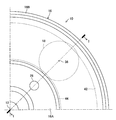
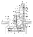
図1は、本発明の第一の実施形態にかかる動力伝達装置10を、回転軸線を通る切断面にて切断して示す部分断面図、図2は、第一の実施形態を図1の右方より見た部分正面図である。なお、図1は、図2のI-Iに沿う断面図である。
図1は、本発明の第一の実施形態にかかる動力伝達装置10を、回転軸線を通る切断面にて切断して示す部分断面図、図2は、第一の実施形態を図1の右方より見た部分正面図である。なお、図1は、図2のI-Iに沿う断面図である。
図1において、動力伝達装置10は、回転軸線12の周りに相対的に回転する太陽歯車部材14及び内歯車部材16と、太陽歯車部材14及び内歯車部材16と噛合する四つの遊星歯車部材18と、キャリア部材78とを有している。キャリア部材78は、四つの遊星歯車部材18を回転軸線12の周りに均等に隔置された状態に維持しつつ、遊星歯車部材18と共に回転軸線12の周りに回転する。
太陽歯車部材14は、回転軸線12に垂直に回転軸線の周りに延在する円環板状部14Dと、該円環板状部の内周部と一体をなすベース部14Bとを有している。ベース部14Bの径方向内側には、回転軸線12に沿って延在する外側中空回転体20が配置されている。ベース部14Bの内周面及びこれに径方向に対向する外側中空回転体20の外面には、回転軸線12に沿って延在するキー溝が設けられ、それらのキー溝にはキー22が嵌め込まれている。太陽歯車部材14は、外側中空回転体20と一体的に回転軸線12の周りに回転可能であると共に、外側中空回転体20に対し回転軸線12に沿って移動可能である。
外側中空回転体20には、回転軸線12に垂直に回転軸線の周りに延在するフランジ20Fが設けられている。フランジ20Fには回転軸線12の周りに均等に隔置された複数のボルト22により、回転軸線12の周りに回転する第一の回転部材としての入力回転部材24が連結されるようになっている。図示の実施形態においては、フランジ20Fは外側中空回転体20と一体に形成されているが、フランジ20Fは外側中空回転体20と別体に形成され、ボルトのような連結手段によって外側中空回転体20と一体的に連結されてもよい。
内歯車部材16は、回転軸線12に垂直に回転軸線の周りに延在するディスク部16Aと、ディスク部の外周部と一体的に接続され回転軸線12に沿って延在する円筒部16Bとを有している。ディスク部16Aの内周部は内側中空回転体26と一体的に接続されており、内側中空回転体26は、外側中空回転体20の径方向内側にて回転軸線12に沿って延在している。ディスク部16Aには、回転軸線12の周りに互いに90°隔置された4本のボルト28及びこれに螺合する図には示されていないナットにより、回転軸線12の周りに回転する第二の回転部材としての出力回転部材30が連結されるようになっている。
外側中空回転体20と内側中空回転体26との間には、回転軸線12に沿って互いに隔置された一対のボールベアリング32が配置されている。一対のボールベアリング32と外側中空回転体20と内側中空回転体26との間の空間は、グリースの如き潤滑剤にて充填されている。一対のボールベアリング32に対し軸線方向両側には一対のシール部材34が配置されており、シール部材34は、ボールベアリング32に粉塵や泥水が侵入しないよう外側中空回転体20と内側中空回転体26との間をシールしている。
四つの遊星歯車部材18及びキャリア部材78は、太陽歯車部材14の円環板状部14Dと内歯車部材16のディスク部16Aとの間に配置されている。遊星歯車部材18は円環板状部14Dに隣接し、キャリア部材78はディスク部16Aに隣接し、遊星歯車部材18及びキャリア部材78は互いに隣接している。
各遊星歯車部材18は、回転軸線12に平行な軸線36に垂直に軸線36の周りに延在する実質的に円板状をなしている。キャリア部材78は、回転軸線12に垂直に回転軸線12の周りに全周に亘り延在する円環板状をなしており、遊星歯車部材18と対向する側に軸線36に沿って延在する円柱状の窪み78Aを有している。各遊星歯車部材18は、軸線36に沿って突出する円柱状の突起18Pを有し、突起18Pが窪み78Aに嵌入することにより、キャリア部材78により軸線36の周りに回転可能に支持されている。
各遊星歯車部材18は、円環板状部14Dの側の側面に摩擦部38Lを有し、キャリア部材78の側の側面に摩擦面18Sを有している。摩擦部38Lは、遊星歯車部材の円板状の本体の側面より隆起した状態で軸線36の周りに環帯状に延在している。なお、遊星歯車部材18が例えば粉末焼結法によって製造されることにより、摩擦部は円板状の本体と一体に形成されてよい。また、摩擦部は、環帯状の摩擦材が本体の側面に接着又は他の手段により固定されることにより形成されてもよい。
キャリア部材78は、内歯車部材16のディスク部16Aと対向する側面にディスク部16Aの摩擦面16Sと摩擦係合可能な摩擦面78SOを有し、遊星歯車部材18と対向する側に摩擦面18Sと摩擦係合可能な摩擦面78SIを有している。太陽歯車部材14の円環板状部14Dの内面は、遊星歯車部材18の摩擦部38Lと摩擦係合可能な摩擦面14Sを有し、円環板状部14Dの外面は平滑である。
各遊星歯車部材18は、外周部に平歯の外歯車40を有している。外歯車40は、径方向外側において内歯車部材16の円筒部16Bの内面に形成された平歯の内歯車42と噛合し、径方向内側において太陽歯車部材14のベース部14Bの外面に形成された平歯の外歯車44と噛合している。よって、太陽歯車部材14が回転軸線12の周りに回転すると、各遊星歯車部材18は軸線36の周りに自転しつつ、太陽歯車部材14及び内歯車部材16に対し回転軸線12の周りに公転する。これにより、内歯車部材16は、太陽歯車部材14に対し回転軸線12の周りに太陽歯車部材14とは逆の方向へ回転し、キャリア部材78は、四つの遊星歯車部材18と共に回転軸線12の周りに太陽歯車部材14及び内歯車部材16に対し回転する。
太陽歯車部材14の円環板状部14Dは、回転軸線12の周りに全周に亘り延在し径方向外方へ開いた環状溝46を有している。環状溝46にはソレノイド48が配置されており、ソレノイド48は回転軸線12の周りに環状に延在している。また、太陽歯車部材14には、環状溝46よりも径方向内側の位置にて径方向に互いに隔置された通電装置50及び52が設けられている。太陽歯車部材14及び内歯車部材16は、常磁性を有する金属材料にて形成されている。遊星歯車部材18及びキャリア部材78は、常磁性を有する金属材料及び常磁性を有しない金属材料の何れにて形成されてもよい。
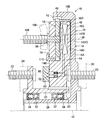
図3に詳細に示されているように、通電装置50及び52は、回転軸線12に沿って延在するシリンダ孔54及び56と、シリンダ孔に嵌合する円柱状のピストン58及び60と、これらのピストンを静止部材62へ向けて付勢する圧縮コイルばね64及び66とを有している。ピストン58及び60は導電体にて形成されているが、円筒状の外周面は電気絶縁材にてコーティングされている。
静止部材62の通電装置50及び52に対向する部分には、それぞれ導電体68及び70が固定されている。導電体68及び70は、対応するピストン58及び60に対向する部分を除き、電気絶縁材72にて電気的に絶縁されている。導電体68、70及び電気絶縁材72は、回転軸線12の周りに環状に延在している。ピストン58及び60の外端は、それぞれ導電体68及び70に通電可能に当接しており、これらのピストンの内端はそれぞれ導線74及び76によりソレノイド48に接続されている。通電装置50及び52を介して行われるソレノイド48に対する通電は、図には示されていない電子制御装置によって制御される。
ソレノイド48に制御電流が通電されていないときには、ソレノイドはディスク部16Aに対し電磁的な吸引力を発生しないので、太陽歯車部材14の円環板状部14Dは、遊星歯車部材18をディスク部16Aに対し押圧しない。よって、太陽歯車部材14、内歯車部材16及び遊星歯車部材18は、遊星歯車機構を構成する歯車部材として相対回転するが、それらの摩擦面は摩擦係合しない。従って、摩擦係合による摩擦力は発生しないので、各部材の相対回転運動を減速させて停止させる作用も生じない。
なお、内歯車部材16は太陽歯車部材14及び外側中空回転体20に対し回転軸線12の周りに逆方向へ回転し、遊星歯車部材18は内歯車部材16及び太陽歯車部材14に対し回転軸線12の周りに公転しつつ軸線36の周りに自転する。よって、入力回転部材24の回転運動が、各歯車部材の歯数比により決定される変速比にて変速されて出力回転部材30へ伝達され、入力回転部材24の回転トルクが、変速比の逆数のトルク伝達比にて出力回転部材30へ伝達される。
これに対し、ソレノイド48に制御電流が通電されると、ソレノイドはディスク部16Aに対し電磁的な吸引力を発生する。ソレノイド48の吸引力は、太陽歯車部材14の円環板状部14Dを遊星歯車部材18に対し押圧し、遊星歯車部材18及びキャリア部材78を内歯車部材16のディスク部16Aに対し押圧する。
よって、円環板状部14Dの摩擦面14S及び遊星歯車部材18の摩擦部38L、遊星歯車部材18の摩擦面18S及びキャリア部材78の摩擦面78SI、キャリア部材78の摩擦面78SO及びディスク部16Aの摩擦面16Sがそれぞれ摩擦係合する。これらの摩擦係合部は、それぞれ摩擦力を発生し、それらの摩擦力は、ソレノイド48の電磁的な吸引力が高くなるほど高くなる。その結果、太陽歯車部材14、内歯車部材16、遊星歯車部材18及びキャリア部材78は相対的に回転しなくなって、一体的に回転軸線12の周りに回転するようになる。従って、入力回転部材24及び出力回転部材30は直結される。
以上の説明より解るように、第一の実施形態においては、太陽歯車部材14、遊星歯車部材18及びキャリア部材78が内歯車部材16に対し回転軸線12に沿って相対的に移動される。そして、太陽歯車部材14と遊星歯車部材18との部材対、遊星歯車部材18とキャリア部材78との部材対、及びキャリア部材78と内歯車部材16との部材対において、それぞれ二つの部材がそれらの側面にて摩擦係合せしめられる。よって、三つの部材対の三つの摩擦係合部により高い摩擦力が発生されるので、従来の動力伝達装置に比して、高い制動力を発生させることができる。従って、各部材の回転を効果的に制動して、三つの歯車部材及びキャリア部材78の相対回転を効率的に停止させることができる。
また、第一の実施形態によれば、遊星歯車部材18は、太陽歯車部材14に対し回転軸線12の周りに公転すると共に、太陽歯車部材14に対し軸線36の周りに自転する。よって、太陽歯車部材14及び遊星歯車部材18の摩擦係合による摩擦力として、公転による相対運動の摩擦力に加えて、自転による相対運動の摩擦力が発生する。従って、公転による相対運動の摩擦力しか発生しない場合に比して、低い押圧力にて効率的に三つの歯車部材及びキャリア部材78の相対回転を阻止することができる。
[第二の実施形態]
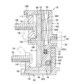
図4に示された第二の実施形態にかかる動力伝達装置10も、太陽歯車部材14、内歯車部材16及び四つの遊星歯車部材18に加えて、キャリア部材78を有している。この実施形においては、後に詳細に説明するように、キャリア部材78には回転軸線12の周りに回転する第三の回転部材としての第二の入力回転部材106が連結される。このことは、後述の第三乃至第五の実施形態についても同様である。
図4に示された第二の実施形態にかかる動力伝達装置10も、太陽歯車部材14、内歯車部材16及び四つの遊星歯車部材18に加えて、キャリア部材78を有している。この実施形においては、後に詳細に説明するように、キャリア部材78には回転軸線12の周りに回転する第三の回転部材としての第二の入力回転部材106が連結される。このことは、後述の第三乃至第五の実施形態についても同様である。
この実施形態の太陽歯車部材14の円環板状部14Dの径方向の寸法は、他の実施形態に比して小さく設定されている。円環板状部14Dと内歯車部材16のディスク部16Aとの間には、キャリア部材78及び遊星歯車部材18が配置され、それぞれ円環板状部14D及びディスク部16Aに隣接し且つ互いに隣接している。キャリア部材78には軸線36に整合して延在するよう四つの植え込みボルト108が圧入又は他の手段により固定されており、植え込みボルト108には第二の入力回転部材106が連結されるようになっている。また、植え込みボルト108には、遊星歯車部材18を軸線36の周りに回転可能に且つ軸線36に沿って相対変位可能に支持するピン98が一体的に形成されている。
遊星歯車部材18は、摩擦部38Rにて内歯車部材16のディスク部16Aの摩擦面16Sと摩擦係合可能であり、摩擦面18Lにてキャリア部材78の摩擦面78SIと摩擦係合可能である。キャリア部材78は、摩擦部78SOにて太陽歯車部材14の円環板状部14Dの摩擦面14Sと摩擦係合可能である。
第一の実施形態と同様に、太陽歯車部材14の円環板状部14にはソレノイド48が設けられており、回転軸線12に沿う方向においてソレノイド48と対向する位置には、静止部材62が配置されている。第一の実施形態における通電装置50及び52と同様の通電装置50及び52が、静止部材62に設けられている。図4には示されていないが、第一の実施形態における導電体68、70及び電気絶縁材72と同様の導電体及び電気絶縁材が、太陽歯車部材14の円環板状部14Dの静止部材62と対向する領域に設けられている。
なお、第二の入力回転部材106は、植え込みボルト108及びキャリア部材78と共に回転軸線12に沿って変位可能である。また、入力回転部材24及び第二の入力回転部材106が回転軸線12の周りに回転することが、静止部材62によって阻害されることがないよう、また、静止部材62を他の静止部材にて支持することができるよう、少なくとも第二の入力回転部材106は中空状をなし、入力回転部材24及び第二の入力回転部材106は、径方向に十分に隔置されていることが好ましい。
この実施形態においても、遊星歯車部材18及びキャリア部材78にはソレノイドの電磁的な吸引力が作用しなくてもよい。よって、遊星歯車部材18及びキャリア部材78は、常磁性を有しない金属材料にて形成されてよい。この実施形態の他の点は、第一の実施形態と同様に構成されている。
ソレノイド48に制御電流が通電されていないときには、ソレノイドは電磁的な吸引力を発生しないので、内歯車部材16のディスク部16Aは吸引されない。よって、太陽歯車部材14の円環板状部14Dは、キャリア部材78に対し押圧されず、キャリア部材78及び遊星歯車部材18は、それぞれ遊星歯車部材18及びディスク部16Aに対し押圧されない。
従って、太陽歯車部材14、内歯車部材16及び遊星歯車部材18は、遊星歯車機構を構成する歯車部材として、第一の実施形態の場合と同様に相対的に回転し、キャリア部材78は、太陽歯車部材14及び内歯車部材16に対し回転軸線12の周りに回転する。よって、入力回転部材24及び/又は第二の入力回転部材106から出力回転部材30へ、回転トルクを伝達させたり回転トルクの伝達を遮断したりすることができる。
例えば、入力回転部材24にエンジンの出力トルクが与えられ、第二の入力回転部材106に電動機の出力トルクが与えられる場合について説明する。
<回転トルクの伝達の遮断>
入力回転部材24にエンジンの出力トルクが与えられ、入力回転部材24を経て太陽歯車部材14に回転トルクが与えられると、その回転トルクによって遊星歯車部材18が軸線36の周りに駆動される。遊星歯車部材18から内歯車部材16へ回転トルクが伝達されないよう、電動機がフリーに回転され又はその出力が制御されると、回転トルクは太陽歯車部材14から遊星歯車部材18を経て内歯車部材16へ伝達されない。よって、入力回転部材24から出力回転部材30への回転トルクの伝達を遮断することができる。
入力回転部材24にエンジンの出力トルクが与えられ、入力回転部材24を経て太陽歯車部材14に回転トルクが与えられると、その回転トルクによって遊星歯車部材18が軸線36の周りに駆動される。遊星歯車部材18から内歯車部材16へ回転トルクが伝達されないよう、電動機がフリーに回転され又はその出力が制御されると、回転トルクは太陽歯車部材14から遊星歯車部材18を経て内歯車部材16へ伝達されない。よって、入力回転部材24から出力回転部材30への回転トルクの伝達を遮断することができる。
<回転トルクの伝達の制御>
電動機の回転速度が制御されることによって軸線36の周りの遊星歯車部材18の回転速度(自転速度)が制御されると、出力回転部材30の回転速度に対する入力回転部材24の回転速度の比が変化する。よって、回転速度の比の逆数である回転トルクの伝達比も変化する。従って、電動機の回転速度を制御することにより、入力回転部材24から出力回転部材30へ伝達される回転トルクを可変制御することができる。
電動機の回転速度が制御されることによって軸線36の周りの遊星歯車部材18の回転速度(自転速度)が制御されると、出力回転部材30の回転速度に対する入力回転部材24の回転速度の比が変化する。よって、回転速度の比の逆数である回転トルクの伝達比も変化する。従って、電動機の回転速度を制御することにより、入力回転部材24から出力回転部材30へ伝達される回転トルクを可変制御することができる。
これに対し、ソレノイド48に制御電流が通電されると、ソレノイド48により発生される電磁的な吸引力によって、内歯車部材16のディスク部16Aが吸引される。太陽歯車部材14の円環板状部14Dは、キャリア部材78に対し押圧され、キャリア部材78及び遊星歯車部材18は、それぞれ遊星歯車部材18及びディスク部16Aに対し押圧される。
よって、遊星歯車部材18の摩擦部38Rとディスク部16Aの摩擦面16Sとが摩擦係合し、遊星歯車部材18の摩擦面18Lとキャリア部材78の摩擦面78SIとが摩擦係合する。更に、キャリア部材78の摩擦部78SOと太陽歯車部材14の円環板状部14の摩擦面14Sとが摩擦係合する。つまり、この実施形態においては、太陽歯車部材14とキャリア部材78との部材対、キャリア部材78と遊星歯車部材18との部材対、及び遊星歯車部材18と内歯車部材16との部材対において、それぞれ二つの部材がそれらの側面にて摩擦係合せしめられて摩擦力が発生される。従って、第一の実施形態と同様に、三つの部材対の三つの摩擦係合部により高い摩擦力を発生させることができる。
上記各摩擦係合部に摩擦力が発生すると、太陽歯車部材14、内歯車部材16及び遊星歯車部材18は相対的に回転しなくなり、キャリア部材78は、太陽歯車部材14及び内歯車部材16に対し回転しなくなる。その結果、これらの部材は一体的に回転軸線12の周りに回転するようになるので、入力回転部材24、第二の入力回転部材106及び出力回転部材30は直結される。
従って、ソレノイド48に制御電流が通電されているときには、下記のように動力伝達装置10による回転トルクの伝達を変化させることができる。
<入力回転部材24からの回転トルクの入力>
入力回転部材24にエンジンの出力トルクが与えられ、第二の入力回転部材106に電動機の出力トルクが与えられない場合には、入力回転部材24に与えられた回転トルクがそのまま動力伝達装置10を経て出力回転部材30へ伝達される。よって、エンジンの出力トルクを制御することにより、出力回転部材30へ伝達される回転トルクを制御することができる。
入力回転部材24にエンジンの出力トルクが与えられ、第二の入力回転部材106に電動機の出力トルクが与えられない場合には、入力回転部材24に与えられた回転トルクがそのまま動力伝達装置10を経て出力回転部材30へ伝達される。よって、エンジンの出力トルクを制御することにより、出力回転部材30へ伝達される回転トルクを制御することができる。
<第二の入力回転部材106からの回転トルクの入力>
入力回転部材24にエンジンの出力トルクが与えられず、第二の入力回転部材106に電動機の出力トルクが与えられる場合には、第二の入力回転部材106に与えられた回転トルクがそのまま動力伝達装置10を経て出力回転部材30へ伝達される。よって、電動機の出力トルクを制御することにより、出力回転部材30へ伝達される回転トルクを制御することができる。
入力回転部材24にエンジンの出力トルクが与えられず、第二の入力回転部材106に電動機の出力トルクが与えられる場合には、第二の入力回転部材106に与えられた回転トルクがそのまま動力伝達装置10を経て出力回転部材30へ伝達される。よって、電動機の出力トルクを制御することにより、出力回転部材30へ伝達される回転トルクを制御することができる。
<入力回転部材24及び106から回転トルクの入力>
入力回転部材24及び第二の入力回転部材106にそれぞれエンジン及び電動機の出力トルクが与えられる場合には、入力回転部材24に与えられた回転トルクと第二の入力回転部材106に与えられた回転トルクとの和が出力回転部材30へ伝達される。この場合にもエンジン及び/又は電動機の出力トルクを制御することにより、出力回転部材30へ伝達される回転トルクを制御することができる。
入力回転部材24及び第二の入力回転部材106にそれぞれエンジン及び電動機の出力トルクが与えられる場合には、入力回転部材24に与えられた回転トルクと第二の入力回転部材106に与えられた回転トルクとの和が出力回転部材30へ伝達される。この場合にもエンジン及び/又は電動機の出力トルクを制御することにより、出力回転部材30へ伝達される回転トルクを制御することができる。
なお、以上の動力伝達装置10の作動は、後述の第三乃至第五の実施形態についても同様である。また、ソレノイド48に制御電流が通電されていない場合及び制御電流が通電されている場合の何れについても、動力伝達装置10による回転トルクの伝達自体は、本発明の要旨をなすものではないので、任意の要領にて行われてよい。
[第三の実施形態]
図5に示された第六の実施形態にかかる動力伝達装置10においては、太陽歯車部材14及び遊星歯車部材18は、キャリア部材78と内歯車部材16のディスク部16Aとの間に配置され、それぞれディスク部16A及びキャリア部材78に隣接し且つ互いに隣接している。太陽歯車部材14のベース部14Bの外周部には、ガード部材110が圧入又は他の手段によって固定されており、ガード部材110はキャリア部材78及び遊星歯車部材18が太陽歯車部材14の円環板状部14Dから離れる方向(図5において左方)へ過剰に移動することを阻止する。
図5に示された第六の実施形態にかかる動力伝達装置10においては、太陽歯車部材14及び遊星歯車部材18は、キャリア部材78と内歯車部材16のディスク部16Aとの間に配置され、それぞれディスク部16A及びキャリア部材78に隣接し且つ互いに隣接している。太陽歯車部材14のベース部14Bの外周部には、ガード部材110が圧入又は他の手段によって固定されており、ガード部材110はキャリア部材78及び遊星歯車部材18が太陽歯車部材14の円環板状部14Dから離れる方向(図5において左方)へ過剰に移動することを阻止する。
図4に示された第二の実施形態と同様に、キャリア部材78には、軸線36に整合して延在するよう四つの植え込みボルト108が圧入又は他の手段により固定されており、植え込みボルト108には第二の入力回転部材106が連結されるようになっている。また、植え込みボルト104には、遊星歯車部材18を軸線36の周りに回転可能に且つ軸線36に沿って相対変位可能に支持するピン98が一体的に形成されている。
太陽歯車部材14の円環板状部14Dは、内歯車部材16のディスク部16Aと対向する側面に摩擦面14SOを有し、摩擦面14SOはディスク部16Aの摩擦面16Sと摩擦係合可能である。また、円環板状部14Dは、遊星歯車部材18と対向する側面に摩擦面14SIを有し、摩擦面14SIは遊星歯車部材18の摩擦部38Rと摩擦係合可能である。太陽歯車部材14のベース部14B及びキャリア部材78の互いに対向する面は、摩擦係合しないよう平滑に加工されており、キャリア部材78の外面及びこれに対向するガード部材110の表面も、摩擦係合しないよう平滑に加工されている。
この実施形態においては、キャリア部材78はソレノイド48による電磁的な吸引力によって吸引されない方がよい。よって、太陽歯車部材14、内歯車部材16及び遊星歯車部材18は、常磁性を有する金属材料にて形成されているが、キャリア部材78は常磁性を有しない金属材料にて形成されている。この実施形態の他の点は、第一の実施形態と同様に構成されている。
ソレノイド48に制御電流が通電されていないときには、ソレノイド48は電磁的な吸引力を発生しないので、各歯車部材は相互に押圧されず、摩擦係合しない。従って、太陽歯車部材14、内歯車部材16及び遊星歯車部材18は、遊星歯車機構を構成する歯車部材として、第一の実施形態の場合と同様に相対的に回転し、キャリア部材78は、太陽歯車部材14及び内歯車部材16に対し回転軸線12の周りに回転する。よって、第二の実施形態と同様に、入力回転部材24及び/又は第二の入力回転部材106から出力回転部材30へ種々の態様にて回転トルクを伝達させることができる。
これに対し、ソレノイド48に制御電流が通電されると、ソレノイドにより発生される電磁的な吸引力によって、内歯車部材16のディスク部16A及び遊星歯車部材18が吸引される。その結果、太陽歯車部材14の円環板状部14Dは、ディスク部16Aに対し押圧され、遊星歯車部材18は、円環板状部14Dに対し押圧される。
よって、太陽歯車部材14、内歯車部材16及び遊星歯車部材18の摩擦部及び摩擦面が摩擦係合し、それらの摩擦係合部(摩擦面16Sと摩擦面14SOとの間、及び摩擦面14SIと摩擦部38Rとの間)に摩擦力が発生する。従って、太陽歯車部材14、内歯車部材16及び遊星歯車部材18は相対的に回転しなくなり、キャリア部材78は、太陽歯車部材14及び内歯車部材16に対し回転しなくなる。その結果、これらの部材は一体的に回転軸線12の周りに回転するようになるので、入力回転部材24、第二の入力回転部材106及び出力回転部材30は直結される。
この実施形態においては、太陽歯車部材14と遊星歯車部材18との部材対、及び太陽歯車部材14と内歯車部材16との部材対において、それぞれ二つの部材がそれらの側面にて摩擦係合せしめられて摩擦力が発生される。従って、二つの部材対の二つの摩擦係合部により摩擦力を発生させることができるので、摩擦係合部が一つである従来の動力伝達装置に比して、高い摩擦力を発生させることができる。
[第四の実施形態]
図6に示された第四の実施形態においては、後に詳細に説明するように、内歯車部材16が四つの遊星歯車部材18と対応する側面にて摩擦係合すると共に、太陽歯車部材14と共働してその一部として機能する部分と対応する側面にて摩擦係合する。
図6に示された第四の実施形態においては、後に詳細に説明するように、内歯車部材16が四つの遊星歯車部材18と対応する側面にて摩擦係合すると共に、太陽歯車部材14と共働してその一部として機能する部分と対応する側面にて摩擦係合する。
この実施形態の太陽歯車部材14は、回転軸線12に沿って延在する実質的に円筒状をなしており、一端(図6で見て右端)においてボールベアリング80を介して内歯車部材16の内周部を回転軸線12の周りに回転可能に支持している。太陽歯車部材14の他端には、径方向外方へ突出するフランジ14Fが一体的に形成されている。フランジ14Fには、回転軸線12の周りに均等に隔置された複数のボルト22により第一の回転部材としての入力回転部材24が連結されるようになっている。図示の実施形態においては、フランジ14Fは太陽歯車部材14と一体に形成されているが、フランジ14Fは太陽歯車部材14と別体に形成され、ボルトのような連結手段によって太陽歯車部材14と一体的に連結されてもよい。
太陽歯車部材14の内周面及びこれに径方向に対向する中空回転部材82のスリーブ部82Aの外面には、回転軸線12に沿って延在し互いに対向するキー溝が設けられ、それらのキー溝にはキー84が嵌め込まれている。中空回転部材82は、太陽歯車部材14に対し回転軸線12に沿って変位可能であるが、太陽歯車部材14に対し回転軸線12の周りに変位不能である。スリーブ部82Aの一端(図6で見て左端)には、太陽歯車部材14が図5で見て左方へスリーブ部82Aに対し過剰に変位することを阻止するロックナット86が螺合により固定されている。
第一の実施形態と同様に、各遊星歯車部材18の外歯車40は、径方向外側にて内歯車部材16の円筒部16Bの内面に形成された内歯車42と噛合し、径方向内側にて太陽歯車部材14の外周面に形成された外歯車44と噛合している。よって、各遊星歯車部材18は、回転軸線12と平行な軸線36に沿って太陽歯車部材14及び内歯車部材16に対し変位可能であると共に、軸線36の周りに回転(自転)可能である。
中空回転部材82のスリーブ部82Aの他端には、回転軸線12に垂直に回転軸線12の周りに延在するフランジ82Fが一体に設けられている。フランジ82Fの内面は、内歯車部材16のディスク部16Aの内周部の外面に隣接している。ディスク部16Aの外面側には、回転軸線12の周りに90°隔置された状態にて四つのボルト孔92が設けられている。図6には示されていないボルトが各ボルト孔92にねじ込まれることにより、第二の回転部材としての出力回転部材30が内歯車部材16に一体的に連結されるようになっている。
内歯車部材16のディスク部16Aは、回転軸線12の周りに全周に亘り延在し径方向外方へ開いた環状溝94を有している。環状溝94にはソレノイド96が配置されており、ソレノイド96は回転軸線12の周りに環状に延在している。内歯車部材16のソレノイド96よりも径方向内側の部分には、第一の実施形態における通電装置50及び52と同様の通電装置50及び52が設けられている。
図5には示されていないが、中空回転部材82のフランジ82Fには、第一の実施形態における導電体68、70及び電気絶縁材72と同様の導電体及び電気絶縁材が設けられている。また、図5には示されていないが、フランジ82Fの外面に近接する静止部材には、該静止部材から通電装置50及び52へ通電するための一対の通電装置が設けられており、フランジ82Fの外面部には、導電体68、70及び電気絶縁材72と同様の導電体及び電気絶縁材が設けられている。なお、内歯車部材16、遊星歯車部材18及びフランジ82Fは、常磁性を有する金属材料にて形成されている。
各遊星歯車部材18は、図1に示された第一の実施形態と同様に、回転軸線12と平行な軸線36に沿って突出する円柱状の突起18Pを有している。突起18Pは、キャリア部材78に設けられ軸線36に沿って延在する窪み78Aに嵌入し、これにより各遊星歯車部材18は、キャリア部材78により軸線36の周りに回転可能に且つキャリア部材78に対し軸線36に沿って変位可能に支持されている。
キャリア部材78には、ピン98を有しない植え込みボルト108が、圧入又は他の手段により固定されている。植え込みボルト108には、図4及び図5に示された第二及び第三の実施形態と同様に、第二の入力回転部材106が連結されるようになっている。この実施形態においても、キャリア部材78は常磁性を有しない金属材料にて形成されている。
内歯車部材16の円筒部16Bの内周部には、キャリア部材78に対し遊星歯車部材18とは反対の側に、Cリング112が固定されている。Cリング112は、キャリア部材78及び遊星歯車部材18が太陽歯車部材14及び内歯車部材16に対し内歯車部材16のディスク部16Aから過剰に離れる方向へ移動することを阻止する。
各遊星歯車部材18は、内歯車部材16に対向する内側の側面に摩擦部38Rを有しており、摩擦部38Rは内歯車部材16のディスク部16Aの内面の摩擦面16SIと摩擦係合し得るようになっている。中空回転部材82のフランジ82Fの内面は、内歯車部材16のディスク部16Aの内周部の外面に設けられた摩擦面16SOと摩擦係合可能な摩擦面82FSを有している。各遊星歯車部材18及びキャリア部材78の互いに対向する面は、摩擦係合しないよう平滑に加工されている。
ソレノイド96に制御電流が通電されていないときには、ソレノイド96は電磁的な吸引力を発生しないので、各歯車部材は相互に押圧されず、摩擦係合しない。従って、太陽歯車部材14、内歯車部材16及び遊星歯車部材18は、遊星歯車機構を構成する歯車部材として、第一の実施形態の場合と同様に相対的に回転し、キャリア部材78は、太陽歯車部材14及び内歯車部材16に対し回転軸線12の周りに回転する。よって、入力回転部材24及び/又は第二の入力回転部材106から出力回転部材30へ種々の態様にて回転トルクを伝達させることができる。
これに対し、ソレノイド96に制御電流が通電されると、ソレノイドにより発生される電磁的な吸引力によって、太陽歯車部材14の一部として機能する中空回転部材82のフランジ82F及び遊星歯車部材18が吸引される。その結果、内歯車部材16のディスク部16Aは、フランジ82Fに対し押圧され、遊星歯車部材18は、ディスク部16Aに対し押圧される。
よって、内歯車部材16のディスク部16A、フランジ82F及び遊星歯車部材18の摩擦部及び摩擦面が摩擦係合し、それらの摩擦係合部(摩擦面16Sと摩擦面82FSとの間、及び摩擦部38Rと摩擦面16Sとの間)に摩擦力が発生する。よって、太陽歯車部材14、内歯車部材16及び遊星歯車部材18は相対的に回転しなくなり、キャリア部材78は、太陽歯車部材14及び内歯車部材16に対し回転しなくなる。その結果、これらの部材は一体的に回転軸線12の周りに回転するようになるので、入力回転部材24、第二の入力回転部材106及び出力回転部材30は直結される。
この実施形態においては、遊星歯車部材18と内歯車部材16との部材対、及び内歯車部材16と太陽歯車部材14の一部として機能する中空回転部材82のフランジ82Fとの部材対において、それぞれ二つの部材がそれらの側面にて摩擦係合せしめられて摩擦力が発生される。従って、第三の実施形態と同様に、二つの部材対の二つの摩擦係合部により摩擦力を発生させることができるので、摩擦係合部が一つである従来の動力伝達装置に比して、高い摩擦力を発生させることができる。
[第五の実施形態]
図7に示された第五の実施形態にかかる動力伝達装置10は、図4に示された第二の実施形態の修正例として構成されており、各遊星歯車部材18はキャリア部材78と内歯車部材16のディスク部16Aとの間に配置されている。この実施形態においては、各遊星歯車部材18は、図6に示された第四の実施形態と同様に、回転軸線12と平行な軸線36に沿って突出する円柱状の突起18Pを有している。突起18Pは、キャリア部材78に設けられ軸線36に沿って延在する窪み78Aに嵌入し、これにより各遊星歯車部材18は、キャリア部材78により軸線36の周りに回転可能に支持されている。
図7に示された第五の実施形態にかかる動力伝達装置10は、図4に示された第二の実施形態の修正例として構成されており、各遊星歯車部材18はキャリア部材78と内歯車部材16のディスク部16Aとの間に配置されている。この実施形態においては、各遊星歯車部材18は、図6に示された第四の実施形態と同様に、回転軸線12と平行な軸線36に沿って突出する円柱状の突起18Pを有している。突起18Pは、キャリア部材78に設けられ軸線36に沿って延在する窪み78Aに嵌入し、これにより各遊星歯車部材18は、キャリア部材78により軸線36の周りに回転可能に支持されている。
各遊星歯車部材18は、ディスク部16Aと対向する側面に摩擦部38Rを有し、キャリア部材78と対向する側面に摩擦部38Lを有している。摩擦部38Rはディスク部16Aの摩擦面16Sと摩擦係合可能であり、摩擦部38Lはキャリア部材78の内面の摩擦面78SIと摩擦係合可能である。この実施形態においては、上記以外の部位に摩擦係合は存在しない。
太陽歯車部材14の内周部は、各遊星歯車部材18及びキャリア部材78に対し径方向内側に存在している。内歯車部材16の円筒部16Bの外端部の内面には、ガード部材112が圧入又は他の手段によって固定されており、ガード部材112はキャリア部材78が遊星歯車部材18から離れる方向(図7において左方)へ過剰に移動することを阻止する。キャリア部材78には、ピン98を有しない植え込みボルト108が、圧入又は他の手段により固定されている。植え込みボルト108には、第三の回転部材としての第二の入力回転部材106が連結されるようになっている。なお、第二の実施形態の場合と同様に、第二の入力回転部材106は、植え込みボルト108及びキャリア部材78と共に回転軸線12に沿って変位可能である。
この実施形態においては、ソレノイドは太陽歯車部材14には設けられておらず、ソレノイド114がキャリア部材78に形成された環状溝116内に設けられている。回転軸線12と平行な方向においてソレノイド114に対向する位置には、静止部材62が配置されている。第一の実施形態における通電装置50及び52と同様の通電装置50及び52が、静止部材62に設けられ、第一の実施形態における導電体68、70及び電気絶縁材72と同様の導電体及び電気絶縁材が、キャリア部材78の静止部材62に対向する領域に設けられている。
この実施形態においては、内歯車部材16及びキャリア部材78は常磁性を有する金属材料にて形成されている。遊星歯車部材18は常磁性を有する金属材料及び常磁性を有しない金属材料の何れにて形成されてもよい。この実施形態の他の点は、第一乃至第三の実施形態と同様に構成されている。
ソレノイド114に制御電流が通電されていないときには、ソレノイド114は電磁的な吸引力を発生しないので、各歯車部材は相互に押圧されず、摩擦係合しない。従って、太陽歯車部材14、内歯車部材16及び遊星歯車部材18は、遊星歯車機構を構成する歯車部材として、第一乃至第三の実施形態の場合と同様に相対的に回転し、キャリア部材78は、太陽歯車部材14及び内歯車部材16に対し回転軸線12の周りに回転する。よって、入力回転部材24及び/又は第二の入力回転部材106から出力回転部材30へ種々の態様にて回転トルクを伝達させることができる。
これに対し、ソレノイド114に制御電流が通電されると、ソレノイド114により発生される電磁的な吸引力によって、内歯車部材16のディスク部16Aが吸引される。その結果、キャリア部材78は、遊星歯車部材18に対し押圧され、これにより遊星歯車部材18は、円環板状部14Dに対し押圧される。
よって、太陽歯車部材14、内歯車部材16及び遊星歯車部材18の摩擦部及び摩擦面が摩擦係合し、それらの摩擦係合部(摩擦部38RとRと摩擦面16Sとの間、及び摩擦部38Lと摩擦面78SIとの間)に摩擦力が発生する。その結果、太陽歯車部材14、内歯車部材16及び遊星歯車部材18は相対的に回転しなくなり、キャリア部材78は、太陽歯車部材14及び内歯車部材16に対し回転しなくなる。従って、これらの部材は一体的に回転軸線12の周りに回転するようになるので、入力回転部材24、第二の入力回転部材106及び出力回転部材30は直結される。
この実施形態においては、キャリア部材78と遊星歯車部材18との部材対、及び遊星歯車部材18と内歯車部材16との部材対において、それぞれ二つの部材がそれらの側面にて摩擦係合せしめられて摩擦力が発生される。従って、第三及び第四の実施形態と同様に、二つの部材対の二つの摩擦係合部により摩擦力を発生させることができるので、摩擦係合部が一つである従来の動力伝達装置に比して、高い摩擦力を発生させることができる。
以上の説明から解るように、各実施形態によれば、太陽歯車部材14、内歯車部材16、遊星歯車部材18及びキャリア部材78のうちの少なくとも二組の二つの部材の間における摩擦係合により、高い摩擦力が発生される。そして、高い摩擦力により、三つの歯車部材及びキャリア部材78の相対回転が停止される。
よって、回転軸線12の周りに相対的に回転する太陽歯車部材14と内歯車部材16との間の摩擦係合により摩擦力が発生される場合に比して、摩擦係合部の数を多くすると共に各摩擦係合部の面積を小さくすることができる。従って、摩擦係合部の数が一つであり摩擦係合部の面積が大きい従来の動力伝達装置に比して、動力伝達装置10を小型化することができる。
また、各実施形態によれば、遊星歯車部材18は、回転軸線12の周りの公転及び軸線36の周りの自転の両者の相対運動により他の歯車部材と摩擦係合し、公転及び自転の両者により摩擦力を発生する。よって、公転のみにより摩擦力が発生される場合に比して、遊星歯車部材18と他の歯車部材とを押圧する力は小さくてよく、押圧力を発生するアクチュエータとして機能するソレノイドも小さくてよい。従って、このことによっても動力伝達装置10を小型化することができる。
また、アクチュエータとして機能する一つのソレノイドの電磁的吸引力により、太陽歯車部材14などの複数の部材が吸引され摩擦係合せしめられる。よって、複数の部材が複数のアクチュエータによって押圧され摩擦係合せしめられる場合に比して、動力伝達装置10の構造を単純化することができると共に、アクチュエータにより消費されるエネルギーに対する摩擦力の比を高くすることができる。よって、このことによっても動力伝達装置10を小型化することができると共に、動力伝達装置10の作動に必要なエネルギーを低減することができる。
特に、第二及び第三の実施形態によれば、第二の入力回転部材106が、遊星歯車部材18又はキャリア部材78と共に回転軸線12の周りに回転するよう、ボルト108によって連結される。よって、二つの入力回転部材と一つの出力回転部材との間又は一つの入力回転部材と二つの出力回転部材との間にて動力の伝達が行われる場合にも、少ないエネルギーにて動力伝達装置10の直結状態と非直結状態との切り替えを効率的に行わせることができる。
更に、第三及び第四の実施形態によれば、第二の入力回転部材106が連結されるキャリア部材78は、軸線36に沿って変位しない。従って、キャリア部材78が軸線36に沿って変位する第一、第二及び第五の実施形態に比して、第二の入力回転部材106とキャリア部材78との連結構造又は第二の入力回転部材106とキャリア部材78との連結構造を単純化することができる。
以上においては、本発明を特定の実施形態について詳細に説明したが、本発明は上述の実施形態に限定されるものではなく、本発明の範囲内にて他の種々の実施形態が可能であることは当業者にとって明らかであろう。
例えば、上述の第二乃至第五の実施形態においては、太陽歯車部材14及び内歯車部材16にそれぞれ入力回転部材24及び出力回転部材30が連結され、キャリア部材78に第二の入力回転部材106が連結されるようになっている。しかし、太陽歯車部材14又はキャリア部材78に一つの出力回転部材が連結され、残りの二つの部材にそれぞれ入力回転部材が連結されてもよい。また、太陽歯車部材14、内歯車部材16及びキャリア部材78の何れか二つの部材にそれぞれ出力回転部材が連結され、残りの一つ部材に一つの入力回転部材が連結されてもよい。
また、上述の第一の実施形態においては、遊星歯車部材18とキャリア部材78とが対応する側面にて摩擦係合するようになっている。しかし、キャリア部材78の径方向の寸法が遊星歯車部材18に比して小さくされると共に、その厚さが小さくされ、遊星歯車部材18の外周部と内歯車部材16のディスク部16Aとが対応する側面にて摩擦係合するよう修正されてもよい。
更に、上述の各実施形態においては、互いに摩擦係合せしめられる歯車部材及びキャリアは、ソレノイドによる電磁力によって移動され押圧されるようになっている。しかし、歯車部材及びキャリアは、油圧式のアクチュエータのような他の駆動装置によって移動され押圧されるようになっていてもよい。
Claims (4)
- 回転軸線の周りに相対的に回転する太陽歯車部材及び内歯車部材と、前記太陽歯車部材及び前記内歯車部材と噛合する遊星歯車部材と、回転軸線と平行な自転軸線の周りに回転可能に前記遊星歯車部材を支持すると共に前記回転軸線の周りに回転するキャリア部材とを有し、前記太陽歯車部材、前記内歯車部材及び前記キャリア部材の一つ及び他の一つは、前記回転軸線の周りに回転する第一及び第二の回転部材がそれぞれ連結されるよう構成され、前記三つの歯車部材及び前記キャリア部材の相対回転が阻止されることにより、前記第一及び第二の回転部材が直結される動力伝達装置において、
前記太陽歯車部材、前記内歯車部材、前記遊星歯車部材及び前記キャリア部材のうちの第一の部材対を構成する二つの部材が、前記回転軸線に沿って相対的に移動され、該二つの部材が対応する側面にて摩擦係合せしめられて相対回転が阻止されると共に、前記太陽歯車部材、前記内歯車部材、前記遊星歯車部材及び前記キャリア部材のうちの第二の部材対を構成する二つの部材が、前記回転軸線に沿って相対的に移動され、該二つの部材が対応する側面にて摩擦係合せしめられて相対回転が阻止されることにより、前記三つの歯車部材及び前記キャリア部材の相対回転が阻止されるように構成された、
動力伝達装置。 - 請求項1に記載の動力伝達装置において、前記第一の部材対の二つの部材は、前記太陽歯車部材及び前記遊星歯車部材であり、前記第二の部材対の二つの部材は、前記遊星歯車部材及び前記キャリア部材である、動力伝達装置。
- 請求項1に記載の動力伝達装置において、前記第一の部材対の二つの部材は、前記内歯車部材及び前記遊星歯車部材であり、前記第二の部材対の二つの部材は、前記遊星歯車部材及び前記キャリア部材である、動力伝達装置。
- 請求項1に記載の動力伝達装置において、前記第一の部材対の二つの部材は、前記内歯車部材及び前記遊星歯車部材であり、前記第二の部材対の二つの部材は、前記太陽歯車部材及び前記内歯車部材である、動力伝達装置。
Priority Applications (1)
| Application Number | Priority Date | Filing Date | Title |
|---|---|---|---|
| JP2015530964A JP6020730B2 (ja) | 2013-08-07 | 2014-08-07 | 動力伝達装置 |
Applications Claiming Priority (2)
| Application Number | Priority Date | Filing Date | Title |
|---|---|---|---|
| JP2013-163822 | 2013-08-07 | ||
| JP2013163822 | 2013-08-07 |
Publications (1)
| Publication Number | Publication Date |
|---|---|
| WO2015020168A1 true WO2015020168A1 (ja) | 2015-02-12 |
Family
ID=52461086
Family Applications (4)
| Application Number | Title | Priority Date | Filing Date |
|---|---|---|---|
| PCT/JP2014/067392 Ceased WO2015019747A1 (ja) | 2013-08-07 | 2014-06-30 | 摩擦ブレーキ装置 |
| PCT/JP2014/070933 Ceased WO2015020167A1 (ja) | 2013-08-07 | 2014-08-07 | 動力伝達装置 |
| PCT/JP2014/070935 Ceased WO2015020168A1 (ja) | 2013-08-07 | 2014-08-07 | 動力伝達装置 |
| PCT/JP2014/070930 Ceased WO2015020166A1 (ja) | 2013-08-07 | 2014-08-07 | 摩擦ブレーキ装置 |
Family Applications Before (2)
| Application Number | Title | Priority Date | Filing Date |
|---|---|---|---|
| PCT/JP2014/067392 Ceased WO2015019747A1 (ja) | 2013-08-07 | 2014-06-30 | 摩擦ブレーキ装置 |
| PCT/JP2014/070933 Ceased WO2015020167A1 (ja) | 2013-08-07 | 2014-08-07 | 動力伝達装置 |
Family Applications After (1)
| Application Number | Title | Priority Date | Filing Date |
|---|---|---|---|
| PCT/JP2014/070930 Ceased WO2015020166A1 (ja) | 2013-08-07 | 2014-08-07 | 摩擦ブレーキ装置 |
Country Status (2)
| Country | Link |
|---|---|
| JP (4) | JP6160696B2 (ja) |
| WO (4) | WO2015019747A1 (ja) |
Cited By (1)
| Publication number | Priority date | Publication date | Assignee | Title |
|---|---|---|---|---|
| US20220298844A1 (en) * | 2021-03-18 | 2022-09-22 | Integrated Design Limited | Access control system |
Families Citing this family (3)
| Publication number | Priority date | Publication date | Assignee | Title |
|---|---|---|---|---|
| CN104204594B (zh) * | 2012-04-07 | 2016-11-02 | 丰田自动车株式会社 | 摩擦制动装置 |
| CN104204596B (zh) * | 2012-04-07 | 2016-10-12 | 丰田自动车株式会社 | 摩擦制动装置 |
| CN104246275B (zh) * | 2012-04-07 | 2017-05-03 | 丰田自动车株式会社 | 摩擦制动装置 |
Citations (2)
| Publication number | Priority date | Publication date | Assignee | Title |
|---|---|---|---|---|
| JP2000006676A (ja) * | 1998-06-23 | 2000-01-11 | Honda Motor Co Ltd | ハイブリッド車両 |
| JP2013107170A (ja) * | 2011-11-21 | 2013-06-06 | Panasonic Eco Solutions Power Tools Co Ltd | 変速装置 |
Family Cites Families (10)
| Publication number | Priority date | Publication date | Assignee | Title |
|---|---|---|---|---|
| DE2633460A1 (de) * | 1976-07-24 | 1978-01-26 | Klaue Hermann | Verstaerkungsfreie vollbelagscheibenbremse, insbesondere fuer kraftfahrzeuge |
| JPS58146723A (ja) * | 1982-02-24 | 1983-09-01 | Shinko Electric Co Ltd | セルフクランプ式高伝達容量の電磁クラツチ又は電磁ブレ−キ |
| JPS6081345U (ja) * | 1983-11-10 | 1985-06-05 | 日産自動車株式会社 | 可変速プ−リ− |
| JPS62126630U (ja) * | 1986-01-31 | 1987-08-11 | ||
| JPH0178755U (ja) * | 1987-11-16 | 1989-05-26 | ||
| JP2000016101A (ja) * | 1998-06-30 | 2000-01-18 | Honda Motor Co Ltd | ハイブリッド車両 |
| JP2000291457A (ja) * | 1999-04-07 | 2000-10-17 | Fuji Heavy Ind Ltd | ハイブリッド車の制御装置 |
| JP2006177532A (ja) * | 2004-12-24 | 2006-07-06 | Hitachi Ltd | ディスクブレーキ |
| JP2008151199A (ja) * | 2006-12-15 | 2008-07-03 | Toyota Motor Corp | 摩擦式伝達率可変型動力伝達装置 |
| CN104204594B (zh) * | 2012-04-07 | 2016-11-02 | 丰田自动车株式会社 | 摩擦制动装置 |
-
2014
- 2014-06-30 WO PCT/JP2014/067392 patent/WO2015019747A1/ja not_active Ceased
- 2014-06-30 JP JP2015530752A patent/JP6160696B2/ja active Active
- 2014-08-07 JP JP2015530963A patent/JP6176328B2/ja not_active Expired - Fee Related
- 2014-08-07 WO PCT/JP2014/070933 patent/WO2015020167A1/ja not_active Ceased
- 2014-08-07 WO PCT/JP2014/070935 patent/WO2015020168A1/ja not_active Ceased
- 2014-08-07 JP JP2015530962A patent/JP6052418B2/ja not_active Expired - Fee Related
- 2014-08-07 WO PCT/JP2014/070930 patent/WO2015020166A1/ja not_active Ceased
- 2014-08-07 JP JP2015530964A patent/JP6020730B2/ja not_active Expired - Fee Related
Patent Citations (2)
| Publication number | Priority date | Publication date | Assignee | Title |
|---|---|---|---|---|
| JP2000006676A (ja) * | 1998-06-23 | 2000-01-11 | Honda Motor Co Ltd | ハイブリッド車両 |
| JP2013107170A (ja) * | 2011-11-21 | 2013-06-06 | Panasonic Eco Solutions Power Tools Co Ltd | 変速装置 |
Cited By (2)
| Publication number | Priority date | Publication date | Assignee | Title |
|---|---|---|---|---|
| US20220298844A1 (en) * | 2021-03-18 | 2022-09-22 | Integrated Design Limited | Access control system |
| US11976699B2 (en) * | 2021-03-18 | 2024-05-07 | Integrated Design Limited | Access control system |
Also Published As
| Publication number | Publication date |
|---|---|
| JP6176328B2 (ja) | 2017-08-09 |
| JPWO2015020168A1 (ja) | 2017-03-02 |
| JP6160696B2 (ja) | 2017-07-12 |
| JPWO2015019747A1 (ja) | 2017-03-02 |
| JP6020730B2 (ja) | 2016-11-02 |
| WO2015020166A1 (ja) | 2015-02-12 |
| JPWO2015020167A1 (ja) | 2017-03-02 |
| WO2015019747A1 (ja) | 2015-02-12 |
| JPWO2015020166A1 (ja) | 2017-03-02 |
| JP6052418B2 (ja) | 2016-12-27 |
| WO2015020167A1 (ja) | 2015-02-12 |
Similar Documents
| Publication | Publication Date | Title |
|---|---|---|
| CN107339398B (zh) | 驱动装置 | |
| JP5284311B2 (ja) | 一体型スピンドルキャリア電気ホイールドライブ | |
| CN107339399B (zh) | 驱动装置 | |
| US10358051B2 (en) | Motor drive unit | |
| US9447830B2 (en) | Electric brake actuator for vehicles | |
| JP6356715B2 (ja) | トルクベクタリング装置 | |
| JP6020730B2 (ja) | 動力伝達装置 | |
| JPWO2011042985A1 (ja) | 回転電機装置 | |
| US10625605B2 (en) | Vehicular power unit | |
| JP2017141868A (ja) | トルクベクタリング装置 | |
| US10203029B2 (en) | Motor drive unit | |
| JP6119842B2 (ja) | 係合装置及び動力伝達装置 | |
| US10054204B2 (en) | Variable output planetary gear set with electromagnetic braking | |
| JP2005515368A (ja) | 複数のスタータ・発電機手段を有するバイワイヤクラッチ | |
| CN109923331A (zh) | 电动致动器 | |
| US10511217B2 (en) | Magnetic clutch device | |
| JP2016017596A (ja) | 噛合式係合装置 | |
| JP2013200012A (ja) | ブレーキ装置及び動力伝達装置 | |
| JP6696271B2 (ja) | 電動アクチュエータ | |
| JP2020158044A (ja) | 電動式アクチュエータおよび電動ブレーキ装置 |
Legal Events
| Date | Code | Title | Description |
|---|---|---|---|
| 121 | Ep: the epo has been informed by wipo that ep was designated in this application |
Ref document number: 14835225 Country of ref document: EP Kind code of ref document: A1 |
|
| ENP | Entry into the national phase |
Ref document number: 2015530964 Country of ref document: JP Kind code of ref document: A |
|
| NENP | Non-entry into the national phase |
Ref country code: DE |
|
| 122 | Ep: pct application non-entry in european phase |
Ref document number: 14835225 Country of ref document: EP Kind code of ref document: A1 |