WO2015019756A1 - クイックコネクタ - Google Patents
クイックコネクタ Download PDFInfo
- Publication number
- WO2015019756A1 WO2015019756A1 PCT/JP2014/067638 JP2014067638W WO2015019756A1 WO 2015019756 A1 WO2015019756 A1 WO 2015019756A1 JP 2014067638 W JP2014067638 W JP 2014067638W WO 2015019756 A1 WO2015019756 A1 WO 2015019756A1
- Authority
- WO
- WIPO (PCT)
- Prior art keywords
- retainer
- checker
- pipe body
- diameter
- claw
- Prior art date
- Legal status (The legal status is an assumption and is not a legal conclusion. Google has not performed a legal analysis and makes no representation as to the accuracy of the status listed.)
- Ceased
Links
Images












Classifications
-
- F—MECHANICAL ENGINEERING; LIGHTING; HEATING; WEAPONS; BLASTING
- F16—ENGINEERING ELEMENTS AND UNITS; GENERAL MEASURES FOR PRODUCING AND MAINTAINING EFFECTIVE FUNCTIONING OF MACHINES OR INSTALLATIONS; THERMAL INSULATION IN GENERAL
- F16L—PIPES; JOINTS OR FITTINGS FOR PIPES; SUPPORTS FOR PIPES, CABLES OR PROTECTIVE TUBING; MEANS FOR THERMAL INSULATION IN GENERAL
- F16L37/00—Couplings of the quick-acting type
- F16L37/08—Couplings of the quick-acting type in which the connection between abutting or axially overlapping ends is maintained by locking members
- F16L37/084—Couplings of the quick-acting type in which the connection between abutting or axially overlapping ends is maintained by locking members combined with automatic locking
- F16L37/088—Couplings of the quick-acting type in which the connection between abutting or axially overlapping ends is maintained by locking members combined with automatic locking by means of a split elastic ring
- F16L37/0885—Couplings of the quick-acting type in which the connection between abutting or axially overlapping ends is maintained by locking members combined with automatic locking by means of a split elastic ring with access to the split elastic ring from a radial or tangential opening in the coupling
-
- F—MECHANICAL ENGINEERING; LIGHTING; HEATING; WEAPONS; BLASTING
- F16—ENGINEERING ELEMENTS AND UNITS; GENERAL MEASURES FOR PRODUCING AND MAINTAINING EFFECTIVE FUNCTIONING OF MACHINES OR INSTALLATIONS; THERMAL INSULATION IN GENERAL
- F16L—PIPES; JOINTS OR FITTINGS FOR PIPES; SUPPORTS FOR PIPES, CABLES OR PROTECTIVE TUBING; MEANS FOR THERMAL INSULATION IN GENERAL
- F16L21/00—Joints with sleeve or socket
- F16L21/02—Joints with sleeve or socket with elastic sealing rings between pipe and sleeve or between pipe and socket, e.g. with rolling or other prefabricated profiled rings
- F16L21/03—Joints with sleeve or socket with elastic sealing rings between pipe and sleeve or between pipe and socket, e.g. with rolling or other prefabricated profiled rings placed in the socket before connection
-
- F—MECHANICAL ENGINEERING; LIGHTING; HEATING; WEAPONS; BLASTING
- F16—ENGINEERING ELEMENTS AND UNITS; GENERAL MEASURES FOR PRODUCING AND MAINTAINING EFFECTIVE FUNCTIONING OF MACHINES OR INSTALLATIONS; THERMAL INSULATION IN GENERAL
- F16L—PIPES; JOINTS OR FITTINGS FOR PIPES; SUPPORTS FOR PIPES, CABLES OR PROTECTIVE TUBING; MEANS FOR THERMAL INSULATION IN GENERAL
- F16L21/00—Joints with sleeve or socket
- F16L21/08—Joints with sleeve or socket with additional locking means
-
- F—MECHANICAL ENGINEERING; LIGHTING; HEATING; WEAPONS; BLASTING
- F16—ENGINEERING ELEMENTS AND UNITS; GENERAL MEASURES FOR PRODUCING AND MAINTAINING EFFECTIVE FUNCTIONING OF MACHINES OR INSTALLATIONS; THERMAL INSULATION IN GENERAL
- F16L—PIPES; JOINTS OR FITTINGS FOR PIPES; SUPPORTS FOR PIPES, CABLES OR PROTECTIVE TUBING; MEANS FOR THERMAL INSULATION IN GENERAL
- F16L37/00—Couplings of the quick-acting type
- F16L37/08—Couplings of the quick-acting type in which the connection between abutting or axially overlapping ends is maintained by locking members
- F16L37/12—Couplings of the quick-acting type in which the connection between abutting or axially overlapping ends is maintained by locking members using hooks, pawls, or other movable or insertable locking members
- F16L37/1225—Couplings of the quick-acting type in which the connection between abutting or axially overlapping ends is maintained by locking members using hooks, pawls, or other movable or insertable locking members using a retaining member the extremities of which, e.g. in the form of a U, engage behind a shoulder of both parts
-
- F—MECHANICAL ENGINEERING; LIGHTING; HEATING; WEAPONS; BLASTING
- F16—ENGINEERING ELEMENTS AND UNITS; GENERAL MEASURES FOR PRODUCING AND MAINTAINING EFFECTIVE FUNCTIONING OF MACHINES OR INSTALLATIONS; THERMAL INSULATION IN GENERAL
- F16L—PIPES; JOINTS OR FITTINGS FOR PIPES; SUPPORTS FOR PIPES, CABLES OR PROTECTIVE TUBING; MEANS FOR THERMAL INSULATION IN GENERAL
- F16L2201/00—Special arrangements for pipe couplings
- F16L2201/10—Indicators for correct coupling
Definitions
- the present invention relates to a quick connector.
- the quick connector described in Patent Document 1 confirms that the annular protrusion of the pipe body is locked to the retainer by moving the checker from the initial position to the locking confirmation position by pushing operation. Further, the quick connector releases the retainer from the annular protrusion of the pipe body by moving the checker from the lock confirmation position to the release position by further pushing operation. That is, the pipe body can be pulled out from the housing and the retainer with the checker moved to the release position.
- the quick connector is in a state where the pipe body can be inserted into the retainer again in a state where the checker is positioned at the locking confirmation position.
- the quick connector since the operator does not perform an operation of moving the checker from the initial position to the locking confirmation function, the quick connector does not exhibit the locking confirmation function.
- the present invention has been made in view of such circumstances, and an object of the present invention is to provide a quick connector capable of reliably exhibiting a locking confirmation function by a checker when a pipe body is reinserted.
- a quick connector according to the present invention is a quick connector that is connected to a pipe body having an annular protrusion on a distal end side, and is a cylindrical housing and a retainer that is integrally formed with or connected to the housing.
- the retainer for locking the annular protrusion of the pipe body inserted from the opening and restricting the removal of the pipe body, and by moving from the initial position to the locking confirmation position by a pushing operation. It is confirmed that the annular protrusion is locked to the retainer, and the retainer is unlocked from the annular protrusion by moving from the locking confirmation position to the release position by further pushing operation.
- a checker includes a reinsertion restricting protrusion.
- the pipe body After the pipe body is pulled out from the housing and the retainer in a state where the checker is moved to the release position, the pipe body is opened again in the state where the checker is moved to the locking confirmation position.
- the re-insertion restricting protrusion When inserting from above, the re-insertion restricting protrusion is caught by the annular protrusion, thereby restricting insertion of the pipe body into the retainer and the housing.
- the reinsertion restricting protrusion In the state where the checker is located at the initial position and the release position, the reinsertion restricting protrusion does not catch on the annular protrusion, thereby inserting or extracting the pipe body from the housing and the retainer. Do not regulate.
- the reinsertion restricting protrusion restricts the insertion of the pipe body. Therefore, it is possible to prompt the operator to move the checker to the initial position once. Then, when the pipe body is reinserted after the checker is moved to the initial position, the check confirmation function by the checker is exhibited as in the initial insertion.
- the retainer has a retainer main body having a first locking portion and a C-shape that is provided closer to the opening of the retainer than the first locking portion of the retainer main body and can be expanded in diameter by elastic deformation. Formed and expanded to allow passage of the annular protrusion of the pipe body, and after the annular protrusion of the pipe body passes, the shape is restored to lock the annular protrusion in the axial direction. And the reinsertion restricting projection is disposed closer to the opening of the retainer than the retainer diameter increasing claw.
- the retainer includes an open end seat member that forms the opening into which the pipe body is inserted, and the reinsertion restricting projection is provided between the retainer diameter-enlarging claw and the open end seat member in the axial direction. Be placed. Thereby, the bending of the reinsertion restricting projection in the axial direction is restricted by the retainer diameter-enlarging claw and the open end seat member. Therefore, in the state where the checker is positioned at the locking confirmation position, the reinsertion of the pipe body is reliably restricted.
- the checker is interposed in an axial gap between the retainer diameter-enlarging claw and the opening end seat member in a state where the checker is positioned at the locking confirmation position, so that the axial direction of the retainer diameter-enlarging claw
- the reinsertion restricting protrusion is provided so as to protrude from the facing surface side of the pair of gap interposed members to the opposite side.
- the retainer main body includes a stopper for restricting an increase in the distance between the opposing surfaces of the pair of gap interposed members.
- the expansion of the distance between the opposing surfaces of the pair of gap interposed members is restricted, and as a result, the reinsertion restricting protrusion is restricted from escaping radially outward. Therefore, after the annular protrusion of the pipe body comes into contact with the reinsertion restricting protrusion, the reinsertion restricting protrusion is restricted from escaping radially outward, so that reinsertion of the pipe body is reliably restricted.
- the retainer main body includes a second locking portion
- the checker includes a checker axial direction deformation claw.
- the checker axial deformation claw is formed through a slit on the opposite side of the opposed surfaces of the pair of gap interposed members, the tip end side is formed to be able to bend and deform in the axial direction, and the retainer enlarged diameter claw is expanded
- the deformed deformation is restricted by the retainer diameter-enlarging claw so that the state of being locked to the second locking portion of the retainer body is maintained, and the second locking portion of the retainer body is maintained.
- the retainer main body is restricted from moving from the initial position to the lock confirmation position, and the retainer main body of the retainer main body is restored to its second shape. Since the locking with respect to the portion can be released, the retainer main body can be moved from the initial position to the locking confirmation position.
- ⁇ ⁇ Locking confirmation function is improved by the checker axial deformation claw. Further, by forming the reinsertion restricting protrusion and the pair of gap interposing members at the axial portion where the checker axial deformation claw is formed, it is possible to reduce the axial size.
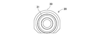
- FIG. 5 is a right side view of FIG. 4.
- FIG. 5 is a left side view of FIG. 4.
- FIG. 6 is a cross-sectional view taken along line AA in FIG. 5.
- FIG. 6 is a sectional view taken along line BB in FIG. 5.
- FIG. 6 is a cross-sectional view taken along the line CC of FIG.
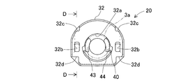
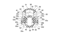
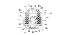
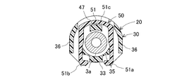
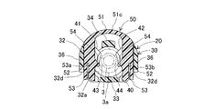
- FIG. 7 is a DD cross-sectional view of FIG. 6. It is a front view (view seen from the direction perpendicular to the axis) of the checker.
- FIG. 14 is a right side view of FIG. 13.
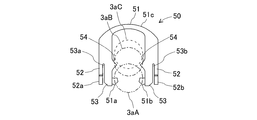
- a two-dot chain line 3aA indicates the relative position of the annular protrusion of the pipe body with respect to the checker when the checker is located at the initial position.
- An alternate long and short dash line 3aB indicates the relative position of the annular protrusion of the pipe body with respect to the checker when the checker is positioned at the locking confirmation position.
- FIG. 14 is a left side view of FIG. 13. It is the figure (plan view) seen from the top of FIG. It is the figure (bottom view) seen from the bottom of FIG.
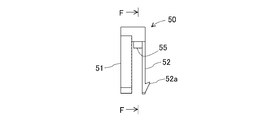
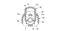
- FIG. 16 is a cross-sectional view taken along line EE in FIG. 15. It is FF sectional drawing of FIG. (State before inserting pipe body)
- FIG. 3 is a sectional view in the axial direction of the quick connector in a state before the pipe body is inserted into the quick connector and the checker is located at the initial position. (Pipe body insertion state)
- FIG. 3 is a sectional view in the axial direction of the quick connector in a state before the pipe body is inserted into the quick connector and the checker is located at the initial position. (Pipe body insertion state)
- FIG. 3 is a sectional view in the axial direction of the quick connector in a state before the pipe body is inserted into the quick connector and the checker is located at the initial position. (Pipe body insertion state)
- FIG. 20 is a sectional view taken along the line G1-G1 of FIG. (State before inserting pipe body)
- FIG. 20 is a sectional view taken along line G2-G2 of FIG. 20, showing a state where the checker diameter-expanding elastic deformation claw is not expanded.
- FIG. 20 is a cross-sectional view taken along line G3-G3 of FIG. (Pipe body insertion intermediate state) It is an axial sectional view of the quick connector in a state where a part of the pipe body is inserted into the quick connector. The checker is in the initial position.
- FIG. 25 is a cross-sectional view taken along the line H1-H1 of FIG.
- FIG. 25 is a cross-sectional view taken along the line H2-H2 of FIG. (Pipe body insertion completion state)
- FIG. 25 is an axial cross-sectional view of the quick connector in a state where the pipe body is further inserted into the quick connector than in the state of FIG. 24. The checker is in the initial position.
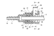
- FIG. 27 is a sectional view taken along the line J1-J1 of FIG. (Pipe body insertion completed state)
- FIG. 28 is a sectional view taken along line J2-J2 of FIG. (Intermediate state of checker movement)
- FIG. 28 is a sectional view in the axial direction of the quick connector in a state where the checker is slid in the direction of slightly pushing the checker into the retainer from the state of FIG. That is, the checker is positioned between the initial position and the locking confirmation position. Moreover, a pipe body shows only an external shape with a dashed-two dotted line.
- FIG. 30 is a sectional view taken along the line K1-K1 of FIG. (Checker movement intermediate state)
- FIG. 30 is a sectional view taken along line K2-K2 of FIG. 30, showing a state in which the checker diameter-expanding elastic deformation claw is expanded.
- FIG. 33 is a cross-sectional view taken along line L1-L1 of FIG.
- FIG. 34 is a sectional view taken along line L2-L2 of FIG. 33, showing a state where the checker-expanded elastic deformation claw is not expanded.
- FIG. 6 is an axial sectional view of the quick connector in a state where the checker is further pushed in from the locking confirmation position and is located at the third position. (Pipe body withdrawn state) FIG.
- FIG. 37 is a cross-sectional view taken along line M1-M1 of FIG. (Pipe body withdrawn state)
- FIG. 36 is a cross-sectional view taken along line M2-M2 of FIG. (Pipe body pulled out state)
- FIG. 37 is a sectional view taken along line M3-M3 of FIG.
- FIG. 37 is a view corresponding to the M3-M3 cross-sectional view of FIG. 36 when the pipe body is reinserted after being removed from the quick connector.
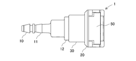
- the quick connector 1 is used, for example, to configure a fuel pipe of an automobile. That is, the quick connector 1 forms a flow path for circulating fuel, for example.
- the quick connector 1 connects a resin tube (not shown) and a pipe body 3 (shown in FIG. 24).
- the quick connector 1 includes a housing 10, a retainer 20, a checker 50, a collar 70, and annular seal members 81 and 82.
- the housing 10 is made of, for example, glass fiber reinforced polyamide, and is integrally formed in a penetrating cylindrical shape.
- the housing 10 shown in FIG. 1 and FIG. 2 shows a shape that penetrates in a straight line, but in addition to this, the passage is formed in a bent shape such as “L-shaped”, for example. You may be made to do.
- a tube connecting portion 11 for connecting a resin tube (not shown) is provided on one end side of the housing 10 (left side in FIGS. 1 and 2).
- the outer peripheral surface of the tube connecting portion 11 is formed in a step shape in the axial direction so as not to come out when the resin tube is fitted.
- a pipe insertion portion 12 having an opening formed so that the tip of the pipe body 3 (shown in FIG. 24) can be inserted.
- an annular seal member 81, 82 made of fluoro rubber and a resin collar 70 are accommodated so as to be sandwiched between the axial directions of the annular seal members 81, 82. ing. The tip of the pipe body 3 is inserted into these inner peripheral sides.
- the retainer 20 is made of, for example, glass fiber reinforced polyamide and is integrally formed in a substantially cylindrical shape.
- the retainer 20 is connected to the pipe insertion portion 12 side of the housing 10 and locks the annular protrusion 3a (shown in FIG. 24) of the pipe body 3.
- the retainer 20 is provided with a checker 50 so as to be movable in the radial direction of the retainer.
- the pipe body 3 is formed in a cylindrical shape, and includes an annular protrusion 3 a (shown in FIG. 24) that protrudes radially outward at a position spaced apart from the tip in the axial direction.
- the retainer 20 allows the pipe body 3 to be inserted from the opening (the right side in FIGS. 1 and 2), and the pipe body 3 is pulled out by being locked to the annular protrusion 3 a of the inserted pipe body 3. regulate. Furthermore, the retainer 20 can also be made into the state which can pull out the pipe body 3 once inserted by canceling
- the checker 50 is made of glass fiber reinforced polyamide, for example, and is a member for confirming that the annular protrusion 3 a of the pipe body 3 is in a state of being locked to the retainer 20.
- the details of the checker 50 will be described below with another column provided, and therefore, in this column, an outline of the checker 50 will be described.
- the checker 50 moves from the initial position (the position shown in FIGS. 20 to 23) with respect to the retainer 20 in the direction of pushing the retainer 20 in the radial direction (downward in FIGS. 1 and 20). (Positions shown in FIGS. 33 to 35).
- the operator can confirm that the annular protrusion 3 a of the pipe body 3 is locked to the retainer 20 by the movement of the checker 50.
- the checker 50 is further released from the locking confirmation position (the position shown in FIGS. 33 to 35) with respect to the retainer 20 (the position shown in FIGS. 36 to 39) in the pushing direction (the lower side in FIGS. 1 and 20). ) To release the engagement between the annular protrusion 3a of the pipe body 3 and the retainer.
- the quick connector 1 of the present embodiment is a retainer housing integrated type and a checker push type. Further, the checker 50 in the quick connector 1 has a release function and is a push release type.
- the detailed structure of the retainer 20 and the checker 50 is demonstrated. After that, the operation of each process of inserting, releasing and reinserting the pipe body 3 with respect to the quick connector 1 will be described.
- the side on which the checker 50 is attached to the retainer 20 is the upper side. That is, it is assumed that the checker 50 moves from the upper side to the lower side with respect to the retainer 20 in the locking confirmation and push release by the checker 50.
- the side which inserts the pipe body 3 among the quick connectors 1 is called a pipe insertion side (right side of FIG. 1), and the opposite side is called an anti-pipe insertion side (left side of FIG. 1).
- the retainer 20 includes a retainer body 30 and a retainer diameter-enlarging claw 40.
- the retainer body 30 is a portion that does not deform in the sense that it is distinguished from the retainer diameter-enlarging claw 40 in a state where the retainer 20 is connected to the housing 10.
- the retainer body 30 includes a cylindrical portion 31, an open end seat member 32, a lower connecting member 33, an upper connecting member 34, a first locking portion 35, and a pair of stoppers 36 and 36.
- the cylindrical portion 31 is fitted into the pipe insertion portion 12 of the housing 10.
- the collar 70 and the annular seal members 81 and 82 are positioned between the stepped portion of the housing 10 and the end surface of the cylindrical portion 31 in the axial direction.
- the open end seat member 32 is provided coaxially so as to face the cylindrical portion 31 at a distance in the axial direction. Further, as shown in FIGS. 5 and 9, the open end seat member 32 is formed with a center hole 32 a having a size capable of passing through the annular protrusion 3 a of the pipe body 3. The center hole 32 a corresponds to the opening of the retainer 20.
- a pair of second locking portions 32b and 32b as a pair of second locking portions 32b and 32b on the left and right sides in FIG. 9 of the center hole 32a when the open end seat member 32 is viewed from the axial direction.
- a hole is formed.
- locking parts 32b and 32b are penetrated and formed in the axial direction, as shown in FIG. More specifically, the upper surfaces of the pair of second locking portions 32b, 32b are inclined so as to go upward from the opposite pipe insertion side to the pipe insertion side in FIG. As will be described later with reference to FIG. 20, this is because the tip protrusions 52 a and 52 b of the checker axial deformation claws 52 and 52 of the checker 50 are caught in the initial state.
- a pair of upper notches 32c forming a plane seat is provided above the pair of second locking portions 32b, 32b on the outer peripheral surface of the open end seat member 32, respectively. 32c is formed.
- the pair of upper cutouts 32c and 32c are for initial positioning of the checker axial deformation claws 52 and 52 in order to obtain an initial state shown in FIG. That is, the pair of upper cutouts 32 c and 32 c are cutouts for facilitating the mounting of the checker 50 to the retainer 20.
- a pair of lower notches 32d forming a plane seat is provided below the pair of second locking portions 32b and 32b on the outer peripheral surface of the open end seat member 32, respectively. 32d is formed.
- the pair of lower notches 32d and 32d are for positioning the checker axial deformation claws 52 and 52 in the locking confirmation state shown in FIG. Details will be described later.
- the lower connecting member 33 is a portion that connects the lower portion of the cylindrical portion 31 and the lower portion of the open end seat member 32 in the axial direction, as shown in FIGS. 5, 10, and 11.
- the upper connecting member 34 connects the upper portion of the cylindrical portion 31 and the upper portion of the open end seat member 32.
- the upper connecting member 34 is provided at a position that does not interfere with the annular protrusion 3a of the pipe body 3 indicated by a two-dot chain line in FIG.
- locking part 35 is formed in the semicircular arc shape (C shape) which opens upwards, as shown in FIG. As shown in FIG. 5, the first locking portion 35 is provided on the cylindrical portion 31 side of the upper side surface of the lower connecting member 33 as shown in FIG. 11. And the 1st latching
- the pair of stoppers 36, 36 connect both side surfaces of the cylindrical portion 31 and both side surfaces of the open end seat member 32, as shown in FIGS. 4, 10 and 11.
- the pair of stoppers 36, 36 are provided at positions that do not interfere with the annular projection 3a of the pipe body 3 indicated by a two-dot chain line in FIG.
- notches 36 a and 36 a are formed on the upper side of the central portion in the axial direction of the pair of stoppers 36 and 36.
- the notches 36a and 36a allow the retainer diameter-enlarging claw 40 to expand, and increase the diameter of the retainer diameter-enlarging claw 40 when the diameter expansion amount reaches a set amount. Has a function to regulate. Details will be described later.
- the retainer diameter-enlarging claw 40 is formed in a C-shape that opens upward as shown in FIG.
- the retainer diameter expanding claw 40 can be expanded in diameter by elastic deformation.
- the retainer diameter-enlarging claw 40 is provided at the substantially central portion in the axial direction as shown in FIG. 5 on the upper side surface of the lower connecting member 33. That is, the retainer diameter-enlarging claw 40 is provided between the opening end seat member 32 and the first locking portion 35 in the axial direction.
- the retainer diameter-enlarging claw 40 is provided at a position that interferes with the annular protrusion 3a of the pipe body 3 indicated by a two-dot chain line in FIG. .
- the retainer diameter-enlarging claw 40 is allowed to pass through the annular protrusion 3a of the pipe body 3 by expanding the diameter. That is, after the annular projecting portion 3 a of the pipe body 3 passes through the axial position of the retainer diameter-enlarging claw 40, the retainer diameter-enlarging claw 40 returns to its shape, so that the retainer diameter-enlarging claw 40 is The function of locking in the axial direction with respect to the portion 3a is exhibited.
- the tip end surfaces 41 and 42 of the retainer diameter-enlarging claw 40 are formed in a shape that is inclined toward the facing surface side (inner side) as shown in FIG. This is because when the distal end surfaces 41 and 42 of the retainer diameter-enlarging claw 40 are pushed by the release portions 55 and 55 of the checker 50, the diameter of the retainer diameter-enlarging claw 40 is increased. Moreover, the end surfaces 43 and 44 on the pipe insertion side of the distal end side of the retainer diameter-enlarging claw 40 are formed so as to be narrower toward the facing surface side as shown in FIG.
- the retainer diameter-enlarging claw 40 interferes with the annular protrusion 3a of the pipe body 3 in a state where the diameter is not expanded. Therefore, in order for the annular protrusion 3 a of the pipe body 3 to pass through the retainer diameter-enlarging claw 40, the annular protrusion 3 a of the pipe body 3 needs to expand the diameter of the retainer diameter-enhancing claw 40. Therefore, by forming the end faces 43 and 44 to be inclined, the diameter can be easily increased when the annular protrusion 3a of the pipe body 3 attempts to pass through the retainer diameter-enlarging claw 40.
- the checker 50 is a member for confirming that the annular protrusion 3 a of the pipe body 3 is locked to the retainer 20 as described in the above-mentioned “Summary of quick connector” column.
- the checker 50 includes a checker diameter-enlarging claw 51, a checker axial direction deformation claw 52, a gap interposed member 53, a reinsertion restriction projection 54, and a release portion 55.
- the checker diameter-enlarging claw 51 is formed in a C-shape (including a U-shape) that can be expanded by elastic deformation. Protrusions 51 a and 51 b projecting toward the opposite surface side (inner side) are formed at both ends of the checker diameter increasing claw 51.
- the pair of checker axial deformation claws 52 and 52 are provided at a distance from the checker diameter-enlarging claw 51 in the left-right direction in FIG. 13 (corresponding to the axial direction in FIG. 1).
- the pair of checker axial direction deforming claws 52, 52 are provided so as to extend in the same direction as the direction (the lower side in FIG. 13) in which the tip ends of the checker enlarged diameter claws 51, 51 extend.
- transformation claws 52 and 52 is formed so that bending deformation is possible in the left-right direction of FIG. 13 (equivalent to the axial direction in FIG. 1).
- the checker axial direction deformation claws 52, 52 are bent and deformed toward the checker diameter-enlarging claws 51, 51 side.
- Protrusions 52a and 52b projecting from the end face (the right side in FIG. 13) opposite to the checker enlarged diameter claws 51 and 51 are formed at the tips of the checker axial direction deformable claws 52 and 52, respectively.
- the pair of gap interposing members 53 and 53 are provided so as to extend in the same direction as the direction in which the checker axial deformation claws 52 and 52 extend. Further, the pair of gap interposed members 53 and 53 are formed through slits 53a and 53b on the radially inner side of the respective checker axial direction deforming claws 52 and 52. That is, even if the checker axial deformation claws 52 and 52 are deformed in the axial direction, the gap interposing members 53 and 53 operate independently of the checker axial deformation claws 52 and 52.
- the reinsertion restricting protrusions 54 and 54 are provided so as to protrude from the facing surfaces of the pair of gap interposing members 53 and 53 to the facing side (inside).
- the reinsertion restricting protrusions 54 and 54 are formed in the vicinity of the center in the extending direction of the pair of gap interposed members 53 and 53. That is, the reinsertion restricting protrusions 54 and 54 are not formed on the distal end side and the proximal end side of the pair of gap interposed members 53 and 53.
- the reinsertion restricting protrusions 54 and 54 are formed in an annular protrusion 3a (FIG. 14) of the pipe body 3 when the checker 50 is located at the initial position, as indicated by a two-dot chain line in FIG. The inside is described as 3aA). Further, as shown by the broken line in FIG. 14, the reinsertion restricting protrusions 54 and 54 are also provided with the annular protrusion 3a of the pipe body 3 (denoted as 3aC in FIG. 14) even when the checker 50 is located at the release position. Does not interfere with. However, the re-insertion restricting projections 54 and 54 are provided with the annular protrusion 3a (3aB in FIG. 14) of the pipe body 3 even when the checker 50 is positioned at the locking confirmation position, as indicated by a one-dot chain line in FIG. ).
- the release portions 55, 55 are located between the checker enlarged claw 51, 51 and the checker axial deformation claw 52 in the axial direction and on the base 51 c side of the checker enlarged claw 51. Is formed.
- the release portions 55 and 55 are formed so as to be inclined from the inside to the outside.
- the release portions 55 and 55 are formed in a shape corresponding to the inclination of the front end surfaces 41 and 42 of the retainer diameter-enlarging claw 40.
- the release portions 55 and 55 are arranged so that the checker 50 is released from the locking confirmation position (position shown in FIGS. 32 to 34) with respect to the retainer 20 to the release position (shown in FIGS. 35 to 37).
- the diameter of the retainer diameter-enlarging claw 40 is expanded by moving to (position).
- the pipe body pre-insertion state is a state in which the checker 50 is located at the initial position with respect to the retainer 20, as shown in FIGS. Specifically, as shown in FIG. 20, the checker 50 is mounted from above the retainer 20.
- the upper side of the retainer 20 corresponds to the opening side of the retainer diameter-enlarging claw 40.
- the tip end side of the checker diameter increasing claw 51 is inserted into the axial gap between the cylindrical portion 31 and the retainer diameter increasing claw 40.
- the tip of the first locking portion 35 of the retainer body 30 is positioned further beyond the ends of the tip protrusions 51a and 51b of the checker diameter-enlarging claw 51 (downward in FIG. 22).
- the checker diameter-enlarging claw 51 is locked to the first locking portion 35 in a state where the diameter is not increased, and thus, the retainer body 30 is restricted from moving downward from the initial position.
- the pair of gap interposed members 53, 53 are inserted into the axial gap between the open end seat member 32 of the retainer body 30 and the retainer enlarged diameter claw 40. .
- the tip protrusions 52 a and 52 b of the checker axial direction deforming claws 52 and 52 enter the second locking portions 32 b and 32 b of the open end seat member 32 of the retainer body 30. It becomes a state. Therefore, when the tip protrusions 52a and 52b of the checker axial direction deforming claws 52 and 52 are locked to the second locking portions 32b and 32b, the checker 50 can be prevented from coming out of the retainer 20 upward. In particular, since it is engaged at an acute angle, it is more effective.
- the pair of reinsertion restricting protrusions 54 and 54 are located at positions where they do not interfere with the annular protrusion 3a of the pipe body 3.
- the annular protrusion 3 a interferes with the retainer diameter-enlarging claw 40. Therefore, as shown in FIG. 25, the retainer diameter-enlarging claw 40 is elastically deformed by the annular protrusion 3a of the pipe body 3 so that the diameter is increased. In particular, since the annular protrusion 3a of the pipe body 3 presses the end surfaces 43 and 44 on the pipe insertion side of the distal end side of the retainer diameter-enlarging claw 40, the diameter of the retainer diameter-enlarging claw 40 is increased relatively easily.
- the checker enlarged claw 51 is located on the side opposite to the pipe insertion side of the retainer enlarged claw 40. Therefore, although the retainer enlarged claw 40 is pressed in the axial direction by the annular protrusion 3a of the pipe body 3, the checker enlarged claw 51 prevents the retainer enlarged claw 40 from being deformed to the anti-pipe insertion side. Also from this, the diameter of the retainer diameter-enlarging claw 40 is expanded relatively easily.
- the diameter of the retainer diameter-enlarging claw 40 increases, so that the annular protrusion 3 a of the pipe body 3 can pass through the position of the retainer diameter-enlarging claw 40.
- the retainer body 30 is formed with stoppers 36 and 36.
- the stoppers 36 and 36 restrict the diameter of the stopper 36 so that the diameter of the retainer does not expand more than a set amount. Therefore, when the retainer diameter-enlarging claw 40 abuts against the stoppers 36, 36, the diameter of the retainer diameter-enlarging claw 40 does not further increase.
- the checker diameter-enlarging claw 51 is not expanded, as shown in FIG. That is, the tip protrusions 51 a and 51 b of the checker diameter-enlarging claw 51 are restricted from moving downward by the first locking portions 35 and 35 of the retainer body 30.
- the pair of checker axial deformation claws 52 and 52 are sandwiched between the retainer diameter-enlarging claw 40 and the open end seat member 32 in the diameter-enlarged state. That is, the checker axial deformation claws 52 and 52 are in a state in which bending deformation in the axial direction is restricted.
- the checker axial deformation claws 52, 52 in order for the checker axial deformation claws 52, 52 to be detached from the second locking portions 32b, 32b of the retainer body 30, the checker axial deformation claws 52, 52 must be bent and deformed in the axial direction.
- the checker axial direction deformation claws 52, 52 when the diameter of the retainer diameter-enlarging claw 40 is increased, the checker axial direction deformation claws 52, 52 are in a state where the deformation in the axial direction is restricted. Therefore, the checker axial direction deformation claws 52 and 52 are maintained in a state of being locked to the second locking portion 32 b of the retainer body 30.
- the checker axial deformation claws 52 and 52 are locked to the second locking portion 32b, so that the checker axial deformation claws 52 and 52 are restricted from moving downward from the initial position with respect to the retainer 20.
- the annular protrusion 3 a of the pipe body 3 has moved to the position of the checker diameter-enlarging claw 51. Therefore, as shown in FIG. 29, the checker enlarged diameter claw 51 is expanded in diameter by the annular protrusion 3 a of the pipe body 3 after passing through the retainer enlarged diameter claw 40. Then, the tip protrusions 51 a and 51 b of the checker expanding claw 51 are separated from the position of the first locking portion 35 of the retainer body 30. That is, the checker diameter-enlarging claw 51 is released from being locked with respect to the first locking portion 35 in the expanded state, and is in a state in which it can move from the initial position to the lower locking confirmation position.
- the checker axial deformation claws 52, 52 are not in a state of being sandwiched between the retainer diameter-enlarging claws 40 as shown in FIG. . Therefore, the checker axial deformation claws 52 and 52 are in a state where they can be bent and deformed in the axial direction. That is, the checker axial deformation claws 52 and 52 can be released from being locked to the second locking portion 32 b of the retainer body 30. Then, the checker axial direction deforming claws 52 and 52 are movable with respect to the retainer body 30 from the initial position to the lower locking confirmation position.
- both the checker diameter-enlarging claw 51 and the checker axial direction deforming claws 52, 52 are movable from the initial position to the locking confirmation position. That is, the checker 50 can move downward with respect to the retainer 20 only when the retainer diameter-enlarging claw 40 is securely engaged with the annular protrusion 3 a of the pipe body 3.
- FIG. 30 shows only the outer shape of the pipe body 3 with a two-dot chain line in order to make the state of the checker axial direction deformation claws 52 and 52 easy to understand. As shown in FIGS.
- the checker axial direction deforming claws 52, 52 are locked to the lower notches 32d, 32d of the open end seat member 32 of the retainer main body 30.
- the checker axial direction deforming claws 52 and 52 are locked to the opening end seat member 32, thereby restricting the movement in the returning direction (upward).
- the tip end surfaces 41 and 42 of the retainer diameter-enlarging claw 40 are located below the release portions 55 and 55 of the checker 50, in order for the checker 50 to move further downward, The diameter of the retainer expanding claw 40 must be increased. In order to increase the diameter of the retainer diameter-enlarging claw 40, the checker 50 must be further pushed in. That is, when the checker 50 reaches the locking confirmation position, no force is applied to the checker 50 and the checker 50 is locked upward and downward with respect to the retainer 20.
- the operator recognizes that the pipe body 3 is securely connected to the quick connector 1. Can do. As described in the pipe body insertion completion state, the pipe body 3 is reliably connected to the quick connector 1 at the time of the pipe body insertion completion state.
- the gap interposed members 53 and 53 have a function of filling the axial gap between the retainer enlarged diameter claw 40 and the open end seat member 32. Have. That is, the gap interposed members 53 and 53 suppress deformation of the retainer diameter-enlarging claw 40 in the axial direction. As a result, it is possible to increase the force for pulling the pipe body 3 out of the retainer 20 in a state where the annular protrusion 3a of the pipe body 3 is locked to the retainer diameter-enlarging claw 40.
- the checker axial deformation claws 52 and 52 are elastic. Regardless of whether or not the deformation is restricted, the elastic deformation is possible. Therefore, the operation of the checker axial direction deformation claws 52, 52 described above can be realized.
- the checker enlarged claw 51 is arranged adjacent to the retainer enlarged claw 40 in the axial direction. Therefore, in a state where the pipe body 3 is not completely inserted, there is a possibility that a state in which the annular protrusion 3a of the pipe body 3 expands both the retainer diameter expanding claw 40 and the checker diameter expanding claw 51 may occur. is there. Then, as shown in FIG. 29, the tip protrusions 51 a and 51 b of the checker enlarged diameter claw 51 are separated from the position of the first locking portion 35 of the retainer main body 30. That is, the checker diameter-enlarging claw 51 is not locked to the first locking portion 35 and can be slid downward.
- the retainer diameter-enlarging claw 40 When the retainer diameter-enlarging claw 40 is expanded, the axial locking with the annular protrusion 3a of the pipe body 3 is released. At this time, the reinsertion restricting protrusions 54, 54 of the checker 50 are located at positions where they do not interfere with the annular protrusion 3a of the pipe body 3, as shown in FIG. Therefore, the operator can pull out the pipe body 3 from the quick connector 1. That is, the release operation of the retainer 20 can be performed by the checker 50. As described above, the checker 50 functions to confirm the locking of the pipe body 3 and release the pipe body 3.
- the reinsertion restricting protrusions 54 are disposed closer to the open end seat member 32 than the retainer diameter-enlarging claw 40. Therefore, when the pipe body 3 is inserted again from the center hole 32a of the open end seat member 32 of the retainer 20, the annular protrusion 3a of the pipe body 3 is brought into contact with the reinsertion restricting protrusion 54, 54 is caught. Therefore, the pipe body 3 is restricted from being inserted into the retainer 20 and the housing 10.
- the reinsertion restricting protrusions 54 and 54 are provided so as to protrude from the opposing surface side of the pair of gap interposing members 53 and 53 to the opposing side. Further, checker axial direction deforming claws 52 and 52 are formed on the opposite side of the pair of gap interposing members 53 and 53 from the opposed surfaces via slits 53a and 53b. As described above, the reinsertion restricting projections 54 and 54 are integrally formed with the gap interposed member 53 and the checker axial deformation claw 52 at the same axial position.
- the pair of integrated members 52, 53, and 54 are restricted from increasing the distance between the opposing surfaces by the stopper 36 of the retainer body 30. Therefore, when the annular protrusion 3a of the pipe body 3 presses the reinsertion restricting protrusions 54, 54, the distance between the opposing surfaces of the pair of reinsertion restricting protrusions 54, 54 does not increase. Therefore, the reinsertion restricting protrusions 54 and 54 maintain the state of being caught by the annular protrusion 3a of the pipe body 3, and reliably restrict the reinsertion of the pipe body 3.
- the reinsertion restricting projection 54 in a tapered shape, if the pipe body 3 is reinserted in the above state, the tip side of the reinsertion restricting protrusion 54 is deformed. Then, after that, by confirming the reinsertion restricting protrusion 54 of the checker 50, it is understood that the pipe body 3 has been inserted without returning the checker 50 to the initial position. However, even if the tip of the reinsertion restricting protrusion 54 is deformed, it is necessary to reliably restrict the insertion of the pipe body 3.
Landscapes
- Engineering & Computer Science (AREA)
- General Engineering & Computer Science (AREA)
- Mechanical Engineering (AREA)
- Quick-Acting Or Multi-Walled Pipe Joints (AREA)
Abstract
パイプ体を再挿入する際に、確実にチェッカーによる係止確認機能を発揮できるクイックコネクタを提供する。チェッカー(50)は、再挿入規制突起(54)を備える。チェッカー(50)をリリース位置へ移動させた状態でパイプ体(3)をハウジング(10)およびリテーナ(20)から引き抜いた後に、チェッカー(50)を係止確認位置に移動させた状態において再びパイプ体(3)をリテーナ(20)の開口部(32a)から挿入する際に、再挿入規制突起(54)は、環状突部(3a)に引っ掛かることにより、パイプ体(3)をリテーナ(20)およびハウジング(10)に挿入することを規制する。
Description
本発明は、クイックコネクタに関するものである。
特許文献1に記載のクイックコネクタは、押し込み操作によってチェッカーを初期位置から係止確認位置へ移動させることにより、パイプ体の環状突部がリテーナに係止された状態であることを確認する。さらに、当該クイックコネクタは、さらなる押し込み操作によってチェッカーを係止確認位置からリリース位置へ移動することにより、パイプ体の環状突部に対するリテーナの係止を解除する。つまり、チェッカーをリリース位置へ移動させた状態で、パイプ体をハウジングおよびリテーナから引き抜くことができる。
しかし、パイプ体をハウジングおよびリテーナから引き抜いた後に、チェッカーが係止確認位置に位置する状態において、クイックコネクタは、再びパイプ体をリテーナに挿入することができる状態になる。このとき、作業者は、チェッカーを初期位置から係止確認機能へ移動させる操作を行わないため、クイックコネクタは、係止確認機能を発揮しない。
本発明は、このような事情に鑑みてなされたものであり、パイプ体を再挿入する際に、確実にチェッカーによる係止確認機能を発揮できるクイックコネクタを提供することを目的とする。
本発明に係るクイックコネクタは、先端側に環状突部を備えるパイプ体に連結されるクイックコネクタであって、筒状のハウジングと、前記ハウジングに一体形成または連結されたリテーナであり、前記リテーナの開口部から挿入された前記パイプ体の前記環状突部に係止して前記パイプ体の抜けを規制する前記リテーナと、押し込み操作によって初期位置から係止確認位置へ移動することにより前記パイプ体の前記環状突部が前記リテーナに係止された状態であることを確認すると共に、さらなる押し込み操作によって前記係止確認位置からリリース位置へ移動することにより前記環状突部に対する前記リテーナの係止を解除するチェッカーと、を備える。
前記チェッカーは、再挿入規制突起を備える。
前記チェッカーを前記リリース位置へ移動させた状態で前記パイプ体を前記ハウジングおよび前記リテーナから引き抜いた後に、前記チェッカーを前記係止確認位置に移動させた状態において再び前記パイプ体を前記リテーナの開口部から挿入する際に、前記再挿入規制突起は、前記環状突部に引っ掛かることにより、前記パイプ体を前記リテーナおよび前記ハウジングに挿入することを規制する。前記チェッカーが前記初期位置および前記リリース位置に位置する状態において、前記再挿入規制突起は、前記環状突部に対して引っ掛からないことにより、前記ハウジングおよび前記リテーナに対して前記パイプ体の挿入または引き抜きを規制しない。
前記チェッカーは、再挿入規制突起を備える。
前記チェッカーを前記リリース位置へ移動させた状態で前記パイプ体を前記ハウジングおよび前記リテーナから引き抜いた後に、前記チェッカーを前記係止確認位置に移動させた状態において再び前記パイプ体を前記リテーナの開口部から挿入する際に、前記再挿入規制突起は、前記環状突部に引っ掛かることにより、前記パイプ体を前記リテーナおよび前記ハウジングに挿入することを規制する。前記チェッカーが前記初期位置および前記リリース位置に位置する状態において、前記再挿入規制突起は、前記環状突部に対して引っ掛からないことにより、前記ハウジングおよび前記リテーナに対して前記パイプ体の挿入または引き抜きを規制しない。
上記によれば、パイプ体を再挿入する際に、チェッカーが係止確認位置に位置する状態であれば、再挿入規制突起がパイプ体の挿入を規制する。従って、作業者に対してチェッカーを一旦初期位置へ移動させることを促すことができる。そして、チェッカーが初期位置へ移動された後に、パイプ体を再挿入する場合には、当初の挿入と同様に、チェッカーによる係止確認機能を発揮する。
以下に、本発明に係るクイックコネクタの好適態様について説明する。
好ましくは、前記リテーナは、第一係止部を有するリテーナ本体と、前記リテーナ本体の前記第一係止部より前記リテーナの開口部側に設けられ、弾性変形により拡径可能なC字形状に形成され、拡径することにより前記パイプ体の前記環状突部を通過可能とし、前記パイプ体の前記環状突部が通過した後に形状復帰することにより前記環状突部に対して軸方向に係止するリテーナ拡径爪と、を備え、前記再挿入規制突起は、前記リテーナ拡径爪より前記リテーナの開口部側に配置される。
これにより、パイプ体の環状突部がリテーナ拡径爪の位置に到達する前に、パイプ体の環状突部が再挿入規制突起に接触する。従って、チェッカーが係止確認位置に位置する状態において、パイプ体の再挿入が確実に規制される。
好ましくは、前記リテーナは、第一係止部を有するリテーナ本体と、前記リテーナ本体の前記第一係止部より前記リテーナの開口部側に設けられ、弾性変形により拡径可能なC字形状に形成され、拡径することにより前記パイプ体の前記環状突部を通過可能とし、前記パイプ体の前記環状突部が通過した後に形状復帰することにより前記環状突部に対して軸方向に係止するリテーナ拡径爪と、を備え、前記再挿入規制突起は、前記リテーナ拡径爪より前記リテーナの開口部側に配置される。
これにより、パイプ体の環状突部がリテーナ拡径爪の位置に到達する前に、パイプ体の環状突部が再挿入規制突起に接触する。従って、チェッカーが係止確認位置に位置する状態において、パイプ体の再挿入が確実に規制される。
好ましくは、前記リテーナは、前記パイプ体を挿入する前記開口部を形成する開口端座部材を備え、前記再挿入規制突起は、前記リテーナ拡径爪と前記開口端座部材との軸方向間に配置される。
これにより、リテーナ拡径爪および開口端座部材によって、再挿入規制突起の軸方向への撓みが規制される。従って、チェッカーが係止確認位置に位置する状態において、パイプ体の再挿入が確実に規制される。
これにより、リテーナ拡径爪および開口端座部材によって、再挿入規制突起の軸方向への撓みが規制される。従って、チェッカーが係止確認位置に位置する状態において、パイプ体の再挿入が確実に規制される。
好ましくは、前記チェッカーは、前記チェッカーが前記係止確認位置に位置する状態において前記リテーナ拡径爪と前記開口端座部材との軸方向隙間に介在することで、前記リテーナ拡径爪の軸方向への変形を規制する一対の隙間介在部材を備え、前記再挿入規制突起は、前記一対の隙間介在部材の対向面側から対向する側に突出するようにそれぞれ設けられる。
パイプ体が正常にリテーナに挿入された後に、パイプ体に抜け力が作用する場合に、リテーナ拡径爪には、パイプ体の環状突部によって開口側へ変形させる力が作用する。しかし、一対の隙間介在部材の存在によって、リテーナ拡径爪が開口側へ変形することが規制される。そして、一対の隙間介在部材を利用して、再挿入規制突起が設けられる。
好ましくは、前記リテーナ本体は、前記一対の隙間介在部材の対向面間距離の拡大を規制するストッパを備える。一対の隙間介在部材の対向面間距離の拡大が規制されることで、結果として、再挿入規制突起が径方向外側へ逃げることが規制される。従って、パイプ体の環状突部が再挿入規制突起に接触した後に、再挿入規制突起が径方向外側への逃げを規制されるため、確実にパイプ体の再挿入が規制される。
好ましくは、前記リテーナ本体は、第二係止部を備え、前記チェッカーは、チェッカー軸方向変形爪を備える。前記チェッカー軸方向変形爪は、前記一対の隙間介在部材の対向面とは反対側にスリットを介して形成され、先端側が前記軸方向に撓み変形可能に形成され、前記リテーナ拡径爪が拡径している状態にて前記リテーナ拡径爪により撓み変形が規制されることで前記リテーナ本体の前記第二係止部に係止された状態を維持し、前記リテーナ本体の前記第二係止部に係止されることで前記リテーナ本体に対して前記初期位置から前記係止確認位置への移動を規制され、前記リテーナ拡径爪が形状復帰した状態にて前記リテーナ本体の前記第二係止部に対する係止が解除可能となることで前記リテーナ本体に対して前記初期位置から前記係止確認位置へ移動可能である。
チェッカー軸方向変形爪により、係止確認機能が向上する。そして、チェッカー軸方向変形爪が形成される軸方向部位に、再挿入規制突起および一対の隙間介在部材を形成することで、軸方向の小型化を図ることができる。
(1.クイックコネクタの概要)
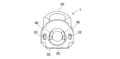
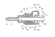
本実施形態のクイックコネクタ1の概要について、図1~図3を参照して説明する。図1に示すように、クイックコネクタ1は、例えば自動車の燃料配管を構成するために用いられるものである。つまり、クイックコネクタ1は、例えば燃料を流通させるための流路を形成している。クイックコネクタ1は、樹脂チューブ(図示せず)とパイプ体3(図24に示す)とを連結する。
本実施形態のクイックコネクタ1の概要について、図1~図3を参照して説明する。図1に示すように、クイックコネクタ1は、例えば自動車の燃料配管を構成するために用いられるものである。つまり、クイックコネクタ1は、例えば燃料を流通させるための流路を形成している。クイックコネクタ1は、樹脂チューブ(図示せず)とパイプ体3(図24に示す)とを連結する。
クイックコネクタ1は、ハウジング10と、リテーナ20と、チェッカー50と、カラー70と、環状シール部材81,82とを備えて構成される。
ハウジング10は、例えばガラス繊維強化ポリアミド製であって、貫通した筒状に一体形成されている。なお、図1および図2に示すハウジング10は、直線状に貫通形成される形状を示しているが、この他に、流路が例えば「L字型」などのように屈曲した形状に貫通形成されるようにしてもよい。
ハウジング10は、例えばガラス繊維強化ポリアミド製であって、貫通した筒状に一体形成されている。なお、図1および図2に示すハウジング10は、直線状に貫通形成される形状を示しているが、この他に、流路が例えば「L字型」などのように屈曲した形状に貫通形成されるようにしてもよい。
図1および図2に示すように、ハウジング10の一端側(図1および図2の左側)には、樹脂チューブ(図示せず)を接続するチューブ接続部11が設けられる。チューブ接続部11の外周面は、樹脂チューブを嵌め込んだ状態で抜けないようにするために、軸方向に向かって段状に形成されている。
一方、ハウジング10の他端側(図1および2の右側)には、パイプ体3(図24に示す)の先端部を挿入可能に開口形成されたパイプ挿入部12が設けられている。パイプ挿入部12の内周側には、例えばフッ素ゴム製の環状シール部材81,82と、環状シール部材81,82の軸方向の間に挟まれるようにして樹脂製のカラー70とが収容されている。これらの内周側にパイプ体3の先端が挿入されることになる。
リテーナ20は、図1および図2に示すように、例えばガラス繊維強化ポリアミド製であって、ほぼ筒状に一体形成されている。リテーナ20は、ハウジング10のパイプ挿入部12側に連結されると共に、パイプ体3の環状突部3a(図24に示す)を係止する。また、リテーナ20には、チェッカー50がリテーナの径方向に移動可能に設けられる。ここで、パイプ体3は、筒状に形成されており、先端から軸方向に距離を隔てた位置に径方向外側に突出形成された環状突部3a(図24に示す)を備える。
つまり、リテーナ20は、開口部(図1および図2の右側)からパイプ体3の挿入を可能とし、挿入されたパイプ体3の環状突部3aに係止することによりパイプ体3の抜けを規制する。さらに、リテーナ20は、パイプ体3の環状突部3aとの係止を解除することにより、一旦挿入したパイプ体3を抜くことが可能な状態にすることもできる。
チェッカー50は、例えばガラス繊維強化ポリアミド製であって、パイプ体3の環状突部3aがリテーナ20に係止された状態であることを確認するための部材である。このチェッカー50の詳細は、以下に別欄を設けて説明するため、本欄では、チェッカー50の概要について説明する。
チェッカー50は、リテーナ20に対して初期位置(図20~図23に示す位置)からリテーナ20に対して径方向に押し込む方向(図1,図20の下方)に移動して、係止確認位置(図33~図35に示す位置)へ到達する。作業者は、チェッカー50の当該移動により、パイプ体3の環状突部3aがリテーナ20に係止された状態であることを確認できる。さらに、チェッカー50は、リテーナ20に対して係止確認位置(図33~図35に示す位置)からさらに押し込む方向(図1,図20の下方)のリリース位置(図36~図39に示す位置)へ移動することにより、パイプ体3の環状突部3aとリテーナとの係止を解除する。
つまり、本実施形態のクイックコネクタ1は、リテーナハウジング一体タイプであって、チェッカープッシュタイプである。さらに、当該クイックコネクタ1におけるチェッカー50は、リリース機能を備えており、プッシュリリースタイプである。以下に、リテーナ20およびチェッカー50の詳細構成について説明する。その後に、クイックコネクタ1に対するパイプ体3の挿入、リリース、および再挿入の各工程の動作について説明する。また、特に断らない限り、以下の説明において、リテーナ20に対してチェッカー50を装着する側を上側とする。つまり、チェッカー50による係止確認およびプッシュリリースにおいて、リテーナ20に対してチェッカー50を上側から下側へ移動するものとして説明する。また、クイックコネクタ1のうちパイプ体3を挿入する側を、パイプ挿入側(図1の右側)と称し、反対側を反パイプ挿入側(図1の左側)と称する。
(2.リテーナの詳細構成)
リテーナ20の詳細構成について、図4~図12を参照して説明する。リテーナ20は、リテーナ本体30と、リテーナ拡径爪40とを備えて構成される。リテーナ本体30は、リテーナ20をハウジング10に連結した状態において、リテーナ拡径爪40と区別する意味で、変形しない部分である。
リテーナ20の詳細構成について、図4~図12を参照して説明する。リテーナ20は、リテーナ本体30と、リテーナ拡径爪40とを備えて構成される。リテーナ本体30は、リテーナ20をハウジング10に連結した状態において、リテーナ拡径爪40と区別する意味で、変形しない部分である。
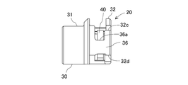
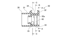
このリテーナ本体30は、筒部31と、開口端座部材32と、下部連結部材33と、上部連結部材34と、第一係止部35と、一対のストッパ36,36とを備える。筒部31は、ハウジング10のパイプ挿入部12に嵌合される。そして、ハウジング10の段部と筒部31の端面との軸方向間に、カラー70および環状シール部材81,82が位置決めされている。
開口端座部材32は、図4~図6および図9に示すように、筒部31から軸方向に距離を隔てて対向するように同軸上に設けられている。さらに、開口端座部材32には、図5および図9に示すように、パイプ体3の環状突部3aを通過可能な大きさの中心孔32aが形成されている。中心孔32aが、リテーナ20の開口部に相当する。
さらに、図6および図9に示すように、開口端座部材32を軸方向から見て中心孔32aの図9の左右両側に、一対の第二係止部32b,32bとしての一対の係止穴が形成されている。一対の第二係止部32b,32bは、図12に示すように、軸方向に貫通形成されている。さらに詳細には、一対の第二係止部32b、32bの上面は、図12の反パイプ挿入側からパイプ挿入側に向かって上側へ行くように傾斜形成されている。これは、後に図20を参照して説明するが、初期状態においてチェッカー50のチェッカー軸方向変形爪52,52の先端突起52a,52bが引っ掛かるようにするためである。
また、図6および図9に示すように、開口端座部材32の外周面のうち一対の第二係止部32b,32bのそれぞれの上方には、平面座を形成する一対の上方切欠32c,32cが形成されている。一対の上方切欠32c,32cは、図21に示す初期状態とするために、チェッカー軸方向変形爪52,52の初期位置決めを行うためのものである。つまり、一対の上方切欠32c,32cは、チェッカー50をリテーナ20に対して装着しやすくするための切欠である。
また、図6および図9に示すように、開口端座部材32の外周面のうち一対の第二係止部32b,32bのそれぞれの下方には、平面座を形成する一対の下方切欠32d,32dが形成されている。一対の下方切欠32d,32dは、図34に示す係止確認状態において、チェッカー軸方向変形爪52,52の位置決めを行うためのものである。詳細は後述する。
下部連結部材33は、図5,図10および図11に示すように、筒部31の下部と開口端座部材32の下部とを軸方向に連結する部分である。上部連結部材34は、図5,図8,図10および図11に示すように、筒部31の上部と開口端座部材32の上部とを連結する。この上部連結部材34は、図11の二点鎖線にて示すパイプ体3の環状突部3aに干渉しない位置に設けられている。
第一係止部35は、図11に示すように、上方に向かって開口する半円弧形状(C字形状)に形成されている。この第一係止部35は、図11に示すように下部連結部材33の上側面のうち、図5に示すように筒部31側に設けられている。そして、第一係止部35は、図11の二点鎖線にて示すパイプ体3の環状突部3aに干渉しない位置に設けられている。この第一係止部35の両端は鋭角状に形成されており、第一係止部35の図11の左右側面は鉛直平面状(上下方向に平行な面状)に形成されている。
一対のストッパ36,36は、図4,図10および図11に示すように、筒部31の両側面と開口端座部材32の両側面とをそれぞれ連結する。一対のストッパ36,36は、図11の二点鎖線にて示すパイプ体3の環状突部3aに干渉しない位置に設けられている。さらに、図4に示すように、一対のストッパ36,36のうち軸方向中央部分の上方側に切欠36a,36aが形成されている。切欠36a,36aは、図25に示すパイプ体挿入中間状態において、リテーナ拡径爪40の拡径を許容すると共に、拡径量が設定量に到達した場合にリテーナ拡径爪40の拡径を規制する機能を有する。詳細は後述する。
リテーナ拡径爪40は、図10に示すように、上方に向かって開口するC字形状に形成されている。このリテーナ拡径爪40は、弾性変形により拡径可能である。このリテーナ拡径爪40は、図10に示すように下部連結部材33の上側面のうち、図5に示すように軸方向のほぼ中央部に設けられている。つまり、リテーナ拡径爪40は、開口端座部材32と第一係止部35との軸方向間に設けられている。
そして、リテーナ拡径爪40は、図10に示すように、拡径していない状態において、図10の二点鎖線にて示すパイプ体3の環状突部3aに干渉する位置に設けられている。ただし、リテーナ拡径爪40が拡径することによりパイプ体3の環状突部3aを通過可能とする。つまり、リテーナ拡径爪40の軸方向位置をパイプ体3の環状突部3aが通過した後に、リテーナ拡径爪40が形状復帰することにより、リテーナ拡径爪40は、パイプ体3の環状突部3aに対して軸方向に係止する機能を発揮する。
さらに、リテーナ拡径爪40の先端面41,42は、図10に示すように、対向面側(内側)に向かって傾斜する形状に形成されている。これは、リテーナ拡径爪40の先端面41,42がチェッカー50のリリース部55,55によって押された場合に、リテーナ拡径爪40が拡径するようにするためである。また、リテーナ拡径爪40の先端側のうちパイプ挿入側の端面43,44は、図8に示すように、対向面側に向かって幅狭となるように傾斜形成されている。上述したように、リテーナ拡径爪40が拡径していない状態においては、パイプ体3の環状突部3aに干渉する。そのため、パイプ体3の環状突部3aがリテーナ拡径爪40を通過するためには、パイプ体3の環状突部3aがリテーナ拡径爪40を拡径する必要がある。そこで、端面43,44を傾斜形成することで、パイプ体3の環状突部3aがリテーナ拡径爪40を通過しようとする際に、容易に拡径できるようになる。
(3.チェッカーの詳細構成)
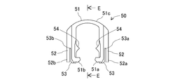
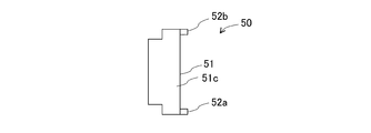
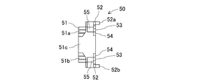
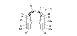
次に、チェッカー50の詳細構成について、図13~図19を参照して説明する。チェッカー50は、上述した「クイックコネクタの概要」欄にて説明したように、パイプ体3の環状突部3aがリテーナ20に係止された状態であることを確認するための部材である。チェッカー50は、チェッカー拡径爪51と、チェッカー軸方向変形爪52と、隙間介在部材53と、再挿入規制突起54と、リリース部55とを備えて構成される。
次に、チェッカー50の詳細構成について、図13~図19を参照して説明する。チェッカー50は、上述した「クイックコネクタの概要」欄にて説明したように、パイプ体3の環状突部3aがリテーナ20に係止された状態であることを確認するための部材である。チェッカー50は、チェッカー拡径爪51と、チェッカー軸方向変形爪52と、隙間介在部材53と、再挿入規制突起54と、リリース部55とを備えて構成される。
チェッカー拡径爪51は、図15に示すように、弾性変形により拡径可能なC字形状(U字形状を含む)に形成されている。チェッカー拡径爪51の両先端には、対向面側(内側)に向かって突出する突起51a,51bが形成されている。
一対のチェッカー軸方向変形爪52,52は、チェッカー拡径爪51に対して図13の左右方向(図1における軸方向に相当)に距離を隔てて設けられている。一対のチェッカー軸方向変形爪52,52は、チェッカー拡径爪51,51の先端側が延びる方向(図13の下側)と同方向へ延びるように設けられている。そして、チェッカー軸方向変形爪52,52の先端側が、図13の左右方向(図1における軸方向に相当)に撓み変形可能に形成されている。つまり、チェッカー軸方向変形爪52,52は、チェッカー拡径爪51,51側に撓み変形する。チェッカー軸方向変形爪52,52の先端には、チェッカー拡径爪51,51とは反対側の端面(図13の右側)から突出する突起52a,52bが形成されている。
一対の隙間介在部材53,53は、図14に示すように、チェッカー軸方向変形爪52,52の延びる方向と同方向へ延びるように設けられている。さらに、一対の隙間介在部材53,53は、それぞれのチェッカー軸方向変形爪52,52の径方向内側にスリット53a,53bを介して形成される。つまり、チェッカー軸方向変形爪52,52が軸方向に変形したとしても、隙間介在部材53,53は、チェッカー軸方向変形爪52,52とは独立した動作を行う。
再挿入規制突起54,54は、図14に示すように、一対の隙間介在部材53,53の対向面側から対向する側(内側)に突出するようにそれぞれ設けられる。再挿入規制突起54,54は、一対の隙間介在部材53,53の延在方向の中央付近に形成される。つまり、一対の隙間介在部材53,53のうち先端側および基端側には、再挿入規制突起54,54が形成されていない。
後に詳述するが、再挿入規制突起54,54は、図14の二点鎖線にて示すように、チェッカー50が初期位置に位置する場合には、パイプ体3の環状突部3a(図14中は3aAと記載)に干渉しない。また、再挿入規制突起54,54は、図14の破線にて示すように、チェッカー50がリリース位置に位置する場合にも、パイプ体3の環状突部3a(図14中は3aCと記載)に干渉しない。ただし、再挿入規制突起54,54は、図14の一点鎖線にて示すように、チェッカー50が係止確認位置に位置する場合にも、パイプ体3の環状突部3a(図14中は3aBと記載)に干渉する。
リリース部55,55は、図13および図18に示すように、チェッカー拡径爪51,51とチェッカー軸方向変形爪52との軸方向間であって、チェッカー拡径爪51の基部51c側に形成されている。このリリース部55,55は、図19に示すように、内側から外側に向かって傾斜形成されている。このリリース部55,55は、リテーナ拡径爪40の先端面41,42の傾斜に対応する形状に形成されている。後に詳細に説明するが、このリリース部55,55は、チェッカー50がリテーナ20に対して係止確認位置(図32~図34に示す位置)から下方のリリース位置(図35~図37に示す位置)へ移動することにより、リテーナ拡径爪40を拡径させる。
(4.動作説明)
次に、クイックコネクタ1にパイプ体3を挿入する際のクイックコネクタ1の各部の動作について説明する。その後に、クイックコネクタ1からパイプ体3を抜く際のクイックコネクタ1の各部の動作について説明する。さらに、クイックコネクタ1に挿入したパイプ体3を抜いた後に、パイプ体3をクイックコネクタ1に再挿入する際のクイックコネクタ1の各部の動作について説明する。
次に、クイックコネクタ1にパイプ体3を挿入する際のクイックコネクタ1の各部の動作について説明する。その後に、クイックコネクタ1からパイプ体3を抜く際のクイックコネクタ1の各部の動作について説明する。さらに、クイックコネクタ1に挿入したパイプ体3を抜いた後に、パイプ体3をクイックコネクタ1に再挿入する際のクイックコネクタ1の各部の動作について説明する。
(5.パイプ体挿入前状態)
まず、パイプ体3をクイックコネクタ1に挿入する前の状態について、図20~図23を参照して説明する。パイプ体挿入前状態とは、図20~図23に示すように、チェッカー50をリテーナ20に対して初期位置に位置する状態である。詳細には、図20に示すように、チェッカー50を、リテーナ20の上方から装着する。ここでいうリテーナ20の上方とは、リテーナ拡径爪40の開口側に相当する。
まず、パイプ体3をクイックコネクタ1に挿入する前の状態について、図20~図23を参照して説明する。パイプ体挿入前状態とは、図20~図23に示すように、チェッカー50をリテーナ20に対して初期位置に位置する状態である。詳細には、図20に示すように、チェッカー50を、リテーナ20の上方から装着する。ここでいうリテーナ20の上方とは、リテーナ拡径爪40の開口側に相当する。
より具体的には、チェッカー拡径爪51の先端側を、筒部31とリテーナ拡径爪40との軸方向隙間に挿入する。このとき、図22に示すように、チェッカー拡径爪51の先端突起51a,51bの端部のさらなる先(図22の下方)には、リテーナ本体30の第一係止部35の先端が位置する。そのため、チェッカー拡径爪51は、拡径していない状態にて第一係止部35に係止されることで、リテーナ本体30に対して初期位置から下方への移動を規制される。
さらに、図20および図21に示すように、初期状態においては、一対の隙間介在部材53,53を、リテーナ本体30の開口端座部材32とリテーナ拡径爪40との軸方向隙間に挿入する。このとき、図20の破線にて示すように、チェッカー軸方向変形爪52,52の先端突起52a,52bが、リテーナ本体30の開口端座部材32の第二係止部32b,32bに進入した状態となる。従って、チェッカー軸方向変形爪52,52の先端突起52a,52bが第二係止部32b,32bに係止した状態となることで、チェッカー50がリテーナ20から上側へ抜けることを防止できる。特に、鋭角に係合しているため、より効果的である。
また、チェッカー50が初期位置に位置する状態において、図23に示すように、一対の再挿入規制突起54,54は、パイプ体3の環状突部3aに対して干渉しない位置に位置する。
(6.パイプ体挿入中間状態)
次に、パイプ体3の先端の一部をクイックコネクタ1の開口端座部材32側から挿入した状態(パイプ体挿入中間状態)について、図24~図26を参照して説明する。パイプ体3をクイックコネクタ1の開口端座部材32側から挿入して行くと、図24に示すように、環状突部3aは、リテーナ本体30の開口端座部材32の中心孔32aを通過する。続いて、図25に示すように、環状突部3aは、チェッカー50の再挿入規制突起54,54に干渉されないため、再挿入規制突起54,54を通過する。
次に、パイプ体3の先端の一部をクイックコネクタ1の開口端座部材32側から挿入した状態(パイプ体挿入中間状態)について、図24~図26を参照して説明する。パイプ体3をクイックコネクタ1の開口端座部材32側から挿入して行くと、図24に示すように、環状突部3aは、リテーナ本体30の開口端座部材32の中心孔32aを通過する。続いて、図25に示すように、環状突部3aは、チェッカー50の再挿入規制突起54,54に干渉されないため、再挿入規制突起54,54を通過する。
続いて、環状突部3aは、リテーナ拡径爪40に干渉する。そのため、図25に示すように、パイプ体3の環状突部3aによって、リテーナ拡径爪40が拡径するように弾性変形する。特に、パイプ体3の環状突部3aは、リテーナ拡径爪40の先端側のうちパイプ挿入側の端面43,44を押圧するため、比較的容易にリテーナ拡径爪40が拡径する。
ここで、リテーナ拡径爪40の反パイプ挿入側には、チェッカー拡径爪51が位置している。従って、リテーナ拡径爪40がパイプ体3の環状突部3aによって軸方向に押しつけられるが、チェッカー拡径爪51によってリテーナ拡径爪40が反パイプ挿入側に変形することを抑制している。このことからも、比較的容易にリテーナ拡径爪40が拡径することになる。
図25に示すように、リテーナ拡径爪40が拡径することで、パイプ体3の環状突部3aがリテーナ拡径爪40の位置を通過することができる。ここで、リテーナ本体30には、ストッパ36,36が形成されている。ストッパ36,36は、リテーナ拡径爪40が拡径する際に、その拡径量が設定量以上拡径しないように規制している。従って、リテーナ拡径爪40は、ストッパ36,36に当接すると、それ以上拡径しない。
リテーナ拡径爪40が上記動作を行っている間、図26に示すように、チェッカー拡径爪51は拡径していない。つまり、チェッカー拡径爪51の先端突起51a,51bは、リテーナ本体30の第一係止部35,35によって下方への移動を規制されている。
このとき、図25に示すように、一対のチェッカー軸方向変形爪52,52は、拡径した状態におけるリテーナ拡径爪40と開口端座部材32との間に挟まれた状態となる。つまり、チェッカー軸方向変形爪52,52は、軸方向への撓み変形が規制された状態となっている。
ここで、チェッカー軸方向変形爪52,52がリテーナ本体30の第二係止部32b,32bから離脱するためには、チェッカー軸方向変形爪52,52が軸方向に撓み変形しなければならない。しかしながら、上述したように、リテーナ拡径爪40が拡径している状態では、チェッカー軸方向変形爪52,52は、軸方向への撓み変形が規制された状態となっている。そのため、チェッカー軸方向変形爪52,52は、リテーナ本体30の第二係止部32bに係止された状態を維持する。そして、チェッカー軸方向変形爪52,52が第二係止部32bに係止されることで、チェッカー軸方向変形爪52,52は、リテーナ20に対して初期位置から下方への移動を規制される。
(7.パイプ体挿入完了状態)
次に、パイプ体3の先端の一部をさらに奥側へ挿入した状態(パイプ体挿入完了状態)について、図27~図29を参照して説明する。図27に示すように、パイプ体3の環状突部3aが、リテーナ拡径爪40の位置を通過する。そうすると、図28に示すように、リテーナ拡径爪40が形状復帰することで、リテーナ拡径爪40がパイプ体3の環状突部3aに対して軸方向に係止することとなる。
次に、パイプ体3の先端の一部をさらに奥側へ挿入した状態(パイプ体挿入完了状態)について、図27~図29を参照して説明する。図27に示すように、パイプ体3の環状突部3aが、リテーナ拡径爪40の位置を通過する。そうすると、図28に示すように、リテーナ拡径爪40が形状復帰することで、リテーナ拡径爪40がパイプ体3の環状突部3aに対して軸方向に係止することとなる。
このとき、図27に示すように、パイプ体3の環状突部3aは、チェッカー拡径爪51の位置に移動している。そのため、図29に示すように、チェッカー拡径爪51は、リテーナ拡径爪40を通過した後のパイプ体3の環状突部3aにより拡径される。そうすると、チェッカー拡径爪51の先端突起51a,51bが、リテーナ本体30の第一係止部35の位置から離れる。つまり、チェッカー拡径爪51は、拡径した状態にて第一係止部35に対する係止が解除されることになり、初期位置から下方の係止確認位置へ移動可能な状態となる。
また、上述したようにリテーナ拡径爪40が形状復帰した状態になることで、図28に示すように、チェッカー軸方向変形爪52,52は、リテーナ拡径爪40に挟まれた状態ではなくなる。そのため、チェッカー軸方向変形爪52,52は、軸方向に撓み変形可能な状態となっている。つまり、チェッカー軸方向変形爪52,52は、リテーナ本体30の第二係止部32bに対する係止が解除可能となる。そうすると、チェッカー軸方向変形爪52,52は、リテーナ本体30に対して初期位置から下方の係止確認位置へ移動可能な状態となる。
このように、チェッカー拡径爪51とチェッカー軸方向変形爪52,52は、共に、初期位置から係止確認位置へ移動可能な状態となる。つまり、リテーナ拡径爪40がパイプ体3の環状突部3aを確実に係止した状態になって初めて、チェッカー50がリテーナ20に対して下方へ移動可能な状態となる。
(8.チェッカー移動中間状態)
次に、作業者は、パイプ体3の挿入を完了した後に、チェッカー50を初期位置から係止確認位置へ移動させる。つまり、作業者によるチェッカー50に対する押し込み操作によって、チェッカー50は、初期位置から係止確認位置へ移動する。ここで、チェッカー50が初期位置と係止確認位置との中間に位置する状態(チェッカー移動中間状態)について、図30~図32を参照して説明する。ここで、図30は、チェッカー軸方向変形爪52,52の状態を分かりやすくするために、パイプ体3の外形のみについて二点鎖線にて示す。図30および図31に示すように、チェッカー軸方向変形爪52,52の先端側が、撓み変形をしている様子が分かる。また、チェッカー拡径爪51は、図32に示すように、リテーナ本体30の第一係止部35の側面に沿って下方へ移動する。
次に、作業者は、パイプ体3の挿入を完了した後に、チェッカー50を初期位置から係止確認位置へ移動させる。つまり、作業者によるチェッカー50に対する押し込み操作によって、チェッカー50は、初期位置から係止確認位置へ移動する。ここで、チェッカー50が初期位置と係止確認位置との中間に位置する状態(チェッカー移動中間状態)について、図30~図32を参照して説明する。ここで、図30は、チェッカー軸方向変形爪52,52の状態を分かりやすくするために、パイプ体3の外形のみについて二点鎖線にて示す。図30および図31に示すように、チェッカー軸方向変形爪52,52の先端側が、撓み変形をしている様子が分かる。また、チェッカー拡径爪51は、図32に示すように、リテーナ本体30の第一係止部35の側面に沿って下方へ移動する。
(9.係止確認完了状態)
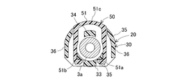
次に、チェッカー50が係止確認位置へ到達した状態(係止確認完了状態)について、図33~図35を参照して説明する。図35に示すように、チェッカー拡径爪51は、形状復帰して、リテーナ本体30の第一係止部35の先端側の下面に係止される。つまり、チェッカー拡径爪51は、第一係止部35に係止されることで、元に戻す方向(上方)への移動を規制される。
次に、チェッカー50が係止確認位置へ到達した状態(係止確認完了状態)について、図33~図35を参照して説明する。図35に示すように、チェッカー拡径爪51は、形状復帰して、リテーナ本体30の第一係止部35の先端側の下面に係止される。つまり、チェッカー拡径爪51は、第一係止部35に係止されることで、元に戻す方向(上方)への移動を規制される。
さらに、チェッカー軸方向変形爪52,52は、図33および図34に示すように、リテーナ本体30の開口端座部材32の下方切欠32d,32dに係止される。つまり、チェッカー軸方向変形爪52,52は、開口端座部材32に係止されることで、元に戻す方向(上方)への移動を規制される。
また、図34に示すように、チェッカー50のリリース部55,55の下方に、リテーナ拡径爪40の先端面41,42が位置することから、チェッカー50がさらに下方へ移動するためには、リテーナ拡径爪40を拡径させなければならない。リテーナ拡径爪40を拡径させるためには、チェッカー50をさらに押し込まなければならない。つまり、チェッカー50が係止確認位置に到達すると、チェッカー50には何の力も作用していな状態となり、リテーナ20に対して上方および下方へ係止された状態となる。
このように、チェッカー50がリテーナ20に押し込まれて、係止確認位置に到達した状態となることで、作業者はパイプ体3がクイックコネクタ1に確実に連結された状態であると認識することができる。なお、上述のパイプ体挿入完了状態にて説明したように、パイプ体挿入完了状態の時点において、パイプ体3はクイックコネクタ1に確実に連結された状態となる。
ところで、パイプ体3をクイックコネクタ1に連結した後において、パイプ体3をクイックコネクタ1から抜くためには、リテーナ拡径爪40を拡径する必要がある。リテーナ拡径爪40の変形を許容する空間があると、相対的に、パイプ体3を抜くための力が小さくなる。
本実施形態においては、チェッカー50が初期位置から係止確認位置まで移動する間において、隙間介在部材53,53が、リテーナ拡径爪40と開口端座部材32との軸方向隙間を埋める機能を有している。つまり、隙間介在部材53,53が、リテーナ拡径爪40の軸方向への変形を抑制する。その結果、パイプ体3の環状突部3aがリテーナ拡径爪40に係止されている状態において、パイプ体3をリテーナ20から抜くための力を大きくすることができる。また、隙間介在部材53,53とチェッカー軸方向変形爪52,52との間にスリット53a,53bが介在しているため、チェッカー軸方向変形爪52,52は、隙間介在部材53,53が弾性変形を規制されているか否かに関わりなく、弾性変形可能な状態となる。従って、上述したチェッカー軸方向変形爪52,52の動作は実現できる。
(10.パイプ体挿入未完状態)
上述したように、パイプ体挿入完了状態では、チェッカー拡径爪51が拡径するが、リテーナ拡径爪40は拡径しない。一方、上述したパイプ体挿入中間状態では、リテーナ拡径爪40が拡径するが、チェッカー拡径爪51は拡径しない。
上述したように、パイプ体挿入完了状態では、チェッカー拡径爪51が拡径するが、リテーナ拡径爪40は拡径しない。一方、上述したパイプ体挿入中間状態では、リテーナ拡径爪40が拡径するが、チェッカー拡径爪51は拡径しない。
ここで、チェッカー拡径爪51は、リテーナ拡径爪40に軸方向に隣接して配置されている。そのため、パイプ体3が完全に奥まで挿入されていない状態では、パイプ体3の環状突部3aが、リテーナ拡径爪40とチェッカー拡径爪51の両者を拡径する状態が発生するおそれがある。そうすると、図29に示すように、チェッカー拡径爪51の先端突起51a,51bが、リテーナ本体30の第一係止部35の位置から離れる。つまり、チェッカー拡径爪51は、第一係止部35に係止されずに、下方へスライド動作可能な状態となる。
しかし、リテーナ拡径爪40が拡径していることにより、チェッカー軸方向変形爪52,52の先端側が撓むことが規制されている。つまり、チェッカー軸方向変形爪52,52が下方へ移動することを規制されている。従って、パイプ体3の環状突部3aがリテーナ拡径爪40を拡径している状態においては、チェッカー50は、下方の係止確認位置へ移動することができない。このように、仮に、パイプ体3の環状突部3aがリテーナ拡径爪40およびチェッカー拡径爪51を拡径する状態になったとしても、チェッカー50による係止確認ができない。従って、作業者は、パイプ体3の挿入が未完状態であることを認識できる。
(11.パイプ体引き抜き状態)
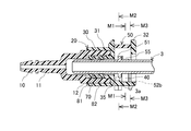
次に、保守などにおいてクイックコネクタ1からパイプ体3を引き抜く場合が生じる。この場合について、図36~図39を参照して説明する。図36~図39に示すように、作業者は、チェッカー50に対して係止確認位置からさらに下方への押し込み操作を行い、チェッカー50をリリース位置へ移動させる。このとき、図37に示すように、チェッカー50のリリース部55,55がリテーナ拡径爪40を拡径する。つまり、作業者は、パイプ体3を引き抜く際には、リテーナ拡径爪40を拡径することができるだけのチェッカー50を押し込む力が必要となる。
次に、保守などにおいてクイックコネクタ1からパイプ体3を引き抜く場合が生じる。この場合について、図36~図39を参照して説明する。図36~図39に示すように、作業者は、チェッカー50に対して係止確認位置からさらに下方への押し込み操作を行い、チェッカー50をリリース位置へ移動させる。このとき、図37に示すように、チェッカー50のリリース部55,55がリテーナ拡径爪40を拡径する。つまり、作業者は、パイプ体3を引き抜く際には、リテーナ拡径爪40を拡径することができるだけのチェッカー50を押し込む力が必要となる。
リテーナ拡径爪40が拡径することで、パイプ体3の環状突部3aとの軸方向の係止が解除される。このとき、チェッカー50の再挿入規制突起54,54は、図39に示すように、パイプ体3の環状突部3aに対して干渉しない位置に位置する。従って、作業者は、パイプ体3をクイックコネクタ1から引き抜くことができる。つまり、チェッカー50によって、リテーナ20のリリース動作を行わせることができる。このように、チェッカー50は、パイプ体3の係止の確認とパイプ体3のリリースとを行うものとして機能する。
(12.パイプ体再挿入時)
パイプ体3をクイックコネクタ1に引き抜いた後に、パイプ体3をクイックコネクタ1へ再挿入する場合について、図40を参照して説明する。作業者が、パイプ体3をクイックコネクタ1から引き抜いた後に、チェッカー50への力の付与を解除すると、チェッカー50は係止確認位置へ移動する。この理由は、リテーナ拡径爪40の形状復帰力が作用するためである。
パイプ体3をクイックコネクタ1に引き抜いた後に、パイプ体3をクイックコネクタ1へ再挿入する場合について、図40を参照して説明する。作業者が、パイプ体3をクイックコネクタ1から引き抜いた後に、チェッカー50への力の付与を解除すると、チェッカー50は係止確認位置へ移動する。この理由は、リテーナ拡径爪40の形状復帰力が作用するためである。
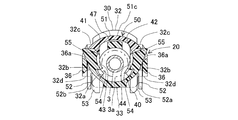
パイプ体3がクイックコネクタ1から引き抜かれた状態で、チェッカー50が係止確認位置に位置する状態では、図40に示すような位置関係となる。このとき、チェッカー50の再挿入規制突起54,54は、パイプ体3の環状突部3a(図40の二点鎖線)に干渉する位置に位置する。
さらに、再挿入規制突起54,54は、リテーナ拡径爪40より開口端座部材32側に配置される。従って、パイプ体3を再びリテーナ20の開口端座部材32の中心孔32aから挿入すると、パイプ体3の環状突部3aは、リテーナ拡径爪40に当接する前に、再挿入規制突起54,54に引っ掛かる。そのため、パイプ体3がリテーナ20およびハウジング10に挿入されることが規制される。
ここで、再挿入規制突起54,54は、一対の隙間介在部材53,53の対向面側から対向する側に突出するようにそれぞれ設けられている。さらに、一対の隙間介在部材53,53の対向面とは反対側には、スリット53a,53bを介して、チェッカー軸方向変形爪52,52が形成されている。このように、再挿入規制突起54,54は、隙間介在部材53およびチェッカー軸方向変形爪52と軸方向同一位置にて一体的に形成されている。
そして、当該一対の一体部材52,53,54は、リテーナ本体30のストッパ36によって、対向面間距離の拡大を規制されている。そのため、パイプ体3の環状突部3aが再挿入規制突起54,54を押し付けたときに、一対の再挿入規制突起54,54の対向面間距離が拡大することはない。従って、再挿入規制突起54,54は、パイプ体3の環状突部3aに引っ掛かる状態を維持し、確実にパイプ体3の再挿入を規制する。
従って、作業者に対してチェッカー50を一旦初期位置へ移動させることを促すことができる。そして、チェッカー50が初期位置へ移動された後に、パイプ体3を再挿入する場合には、当初の挿入と同様に、チェッカー50による係止確認機能を発揮する。
また、再挿入規制突起54を先細形状にすることで、仮に、上記状態にてパイプ体3が再挿入された場合には、再挿入規制突起54の先端側が変形することになる。そうすると、事後的に、チェッカー50の再挿入規制突起54を確認することで、チェッカー50を初期位置に戻さずに、パイプ体3の挿入動作を行ったことが分かる。ただし、再挿入規制突起54の先端が変形したとしても、パイプ体3の挿入を確実に規制できるようにすることが必要である。
1:クイックコネクタ、 3:パイプ体、 3a:環状突部、 10:ハウジング、 20:リテーナ、 30:リテーナ本体、 32:開口端座部材、 32a:中心孔(リテーナの開口部)、 32b:第二係止部、 35:第一係止部、 36:ストッパ、 40:リテーナ拡径爪、 50:チェッカー、 51:チェッカー拡径爪、 52:チェッカー軸方向変形爪、 53:隙間介在部材、 53a,53b:スリット、 54:再挿入規制突起、 55:リリース部
Claims (6)
- 先端側に環状突部を備えるパイプ体に連結されるクイックコネクタであって、
筒状のハウジングと、
前記ハウジングに一体形成または連結されたリテーナであり、前記リテーナの開口部から挿入された前記パイプ体の前記環状突部に係止して前記パイプ体の抜けを規制する前記リテーナと、
押し込み操作によって初期位置から係止確認位置へ移動することにより前記パイプ体の前記環状突部が前記リテーナに係止された状態であることを確認すると共に、さらなる押し込み操作によって前記係止確認位置からリリース位置へ移動することにより前記環状突部に対する前記リテーナの係止を解除するチェッカーと、
を備え、
前記チェッカーは、再挿入規制突起を備え、
前記チェッカーを前記リリース位置へ移動させた状態で前記パイプ体を前記ハウジングおよび前記リテーナから引き抜いた後に、前記チェッカーを前記係止確認位置に移動させた状態において再び前記パイプ体を前記リテーナの開口部から挿入する際に、前記再挿入規制突起は、前記環状突部に引っ掛かることにより、前記パイプ体を前記リテーナおよび前記ハウジングに挿入することを規制し、
前記チェッカーが前記初期位置および前記リリース位置に位置する状態において、前記再挿入規制突起は、前記環状突部に対して引っ掛からないことにより、前記ハウジングおよび前記リテーナに対して前記パイプ体の挿入または引き抜きを規制しない、
クイックコネクタ。 - 前記リテーナは、
第一係止部を有するリテーナ本体と、
前記リテーナ本体の前記第一係止部より前記リテーナの開口部側に設けられ、弾性変形により拡径可能なC字形状に形成され、拡径することにより前記パイプ体の前記環状突部を通過可能とし、前記パイプ体の前記環状突部が通過した後に形状復帰することにより前記環状突部に対して軸方向に係止するリテーナ拡径爪と、
を備え、
前記再挿入規制突起は、前記リテーナ拡径爪より前記リテーナの開口部側に配置される、
請求項1のクイックコネクタ。 - 前記リテーナは、前記パイプ体を挿入する前記開口部を形成する開口端座部材を備え、
前記再挿入規制突起は、前記リテーナ拡径爪と前記開口端座部材との軸方向間に配置される、
請求項2のクイックコネクタ。 - 前記チェッカーは、前記チェッカーが前記係止確認位置に位置する状態において前記リテーナ拡径爪と前記開口端座部材との軸方向隙間に介在することで、前記リテーナ拡径爪の軸方向への変形を規制する一対の隙間介在部材を備え、
前記再挿入規制突起は、前記一対の隙間介在部材の対向面側から対向する側に突出するようにそれぞれ設けられる、
請求項3のクイックコネクタ。 - 前記リテーナ本体は、前記一対の隙間介在部材の対向面間距離の拡大を規制するストッパを備える、請求項4のクイックコネクタ。
- 前記リテーナ本体は、第二係止部を備え、
前記チェッカーは、チェッカー軸方向変形爪を備え、
前記チェッカー軸方向変形爪は、
前記一対の隙間介在部材の対向面とは反対側にスリットを介して形成され、
先端側が前記軸方向に撓み変形可能に形成され、
前記リテーナ拡径爪が拡径している状態にて前記リテーナ拡径爪により撓み変形が規制されることで前記リテーナ本体の前記第二係止部に係止された状態を維持し、
前記リテーナ本体の前記第二係止部に係止されることで前記リテーナ本体に対して前記初期位置から前記係止確認位置への移動を規制され、
前記リテーナ拡径爪が形状復帰した状態にて前記リテーナ本体の前記第二係止部に対する係止が解除可能となることで前記リテーナ本体に対して前記初期位置から前記係止確認位置へ移動可能である、
請求項4または5のクイックコネクタ。
Priority Applications (3)
| Application Number | Priority Date | Filing Date | Title |
|---|---|---|---|
| DE112014003608.0T DE112014003608B4 (de) | 2013-08-05 | 2014-07-02 | Schnellverbinder |
| CN201480033013.7A CN105358891B (zh) | 2013-08-05 | 2014-07-02 | 快速连接器 |
| US14/699,628 US10047888B2 (en) | 2013-08-05 | 2015-04-29 | Quick connector |
Applications Claiming Priority (2)
| Application Number | Priority Date | Filing Date | Title |
|---|---|---|---|
| JP2013-162606 | 2013-08-05 | ||
| JP2013162606A JP5674879B2 (ja) | 2013-08-05 | 2013-08-05 | クイックコネクタ |
Related Child Applications (1)
| Application Number | Title | Priority Date | Filing Date |
|---|---|---|---|
| US14/699,628 Continuation US10047888B2 (en) | 2013-08-05 | 2015-04-29 | Quick connector |
Publications (1)
| Publication Number | Publication Date |
|---|---|
| WO2015019756A1 true WO2015019756A1 (ja) | 2015-02-12 |
Family
ID=52461095
Family Applications (1)
| Application Number | Title | Priority Date | Filing Date |
|---|---|---|---|
| PCT/JP2014/067638 Ceased WO2015019756A1 (ja) | 2013-08-05 | 2014-07-02 | クイックコネクタ |
Country Status (5)
| Country | Link |
|---|---|
| US (1) | US10047888B2 (ja) |
| JP (1) | JP5674879B2 (ja) |
| CN (1) | CN105358891B (ja) |
| DE (1) | DE112014003608B4 (ja) |
| WO (1) | WO2015019756A1 (ja) |
Families Citing this family (5)
| Publication number | Priority date | Publication date | Assignee | Title |
|---|---|---|---|---|
| JP6149081B2 (ja) * | 2015-09-24 | 2017-06-14 | 住友理工株式会社 | クイックコネクタ |
| JP6722607B2 (ja) * | 2017-02-28 | 2020-07-15 | 三桜工業株式会社 | 配管継手 |
| US11796099B2 (en) * | 2019-08-22 | 2023-10-24 | Cooper-Standard Automotive Inc. | Connector having a pilot with an indicator |
| JP7150210B1 (ja) * | 2022-07-08 | 2022-10-07 | 三桜工業株式会社 | 配管継手 |
| JP7150209B1 (ja) * | 2022-07-08 | 2022-10-07 | 三桜工業株式会社 | 配管継手 |
Citations (9)
| Publication number | Priority date | Publication date | Assignee | Title |
|---|---|---|---|---|
| JP2004060884A (ja) * | 2002-06-04 | 2004-02-26 | Piolax Inc | チェック機能内蔵コネクタ |
| JP2004211891A (ja) * | 2002-12-18 | 2004-07-29 | Piolax Inc | チェッカー付きコネクタ |
| JP2006183833A (ja) * | 2004-12-28 | 2006-07-13 | Nitta Moore Co | コネクタ装置 |
| JP2006313013A (ja) * | 2005-05-03 | 2006-11-16 | Ti Group Automotive Systems Llc | 急速継手用の冗長ラッチ/確認機構 |
| JP2007255668A (ja) * | 2006-03-24 | 2007-10-04 | Tokai Rubber Ind Ltd | クイックコネクタ |
| JP2008509361A (ja) * | 2004-08-11 | 2008-03-27 | アー ライモント エ カンパニュイ | 連結装置 |
| JP2010078077A (ja) * | 2008-09-26 | 2010-04-08 | Sanoh Industrial Co Ltd | クイックコネクタ |
| JP2010203611A (ja) * | 2009-03-02 | 2010-09-16 | Ti Group Automotive Systems Llc | シールアセンブリー・リテーナ付クイックコネクター |
| JP4937426B1 (ja) * | 2010-09-30 | 2012-05-23 | 東海ゴム工業株式会社 | クイックコネクタ |
Family Cites Families (5)
| Publication number | Priority date | Publication date | Assignee | Title |
|---|---|---|---|---|
| JP4198487B2 (ja) * | 2003-02-20 | 2008-12-17 | 三桜工業株式会社 | クイックコネクタの防塵キャップ |
| US9016729B2 (en) * | 2005-12-06 | 2015-04-28 | Sumitomo Riko Company Limited | Quick connector and checker |
| DE102006047267B4 (de) * | 2006-10-04 | 2010-02-04 | A. Raymond Et Cie | Kupplungsteil für eine Fluidleitungskupplung |
| US20100052315A1 (en) * | 2008-08-28 | 2010-03-04 | Ti Group Automotive Systems, Llc | Quick connector coupling with lateral stabilization |
| JP6067366B2 (ja) * | 2012-12-20 | 2017-01-25 | 住友理工株式会社 | 配管接続構造 |
-
2013
- 2013-08-05 JP JP2013162606A patent/JP5674879B2/ja active Active
-
2014
- 2014-07-02 WO PCT/JP2014/067638 patent/WO2015019756A1/ja not_active Ceased
- 2014-07-02 DE DE112014003608.0T patent/DE112014003608B4/de active Active
- 2014-07-02 CN CN201480033013.7A patent/CN105358891B/zh active Active
-
2015
- 2015-04-29 US US14/699,628 patent/US10047888B2/en active Active
Patent Citations (9)
| Publication number | Priority date | Publication date | Assignee | Title |
|---|---|---|---|---|
| JP2004060884A (ja) * | 2002-06-04 | 2004-02-26 | Piolax Inc | チェック機能内蔵コネクタ |
| JP2004211891A (ja) * | 2002-12-18 | 2004-07-29 | Piolax Inc | チェッカー付きコネクタ |
| JP2008509361A (ja) * | 2004-08-11 | 2008-03-27 | アー ライモント エ カンパニュイ | 連結装置 |
| JP2006183833A (ja) * | 2004-12-28 | 2006-07-13 | Nitta Moore Co | コネクタ装置 |
| JP2006313013A (ja) * | 2005-05-03 | 2006-11-16 | Ti Group Automotive Systems Llc | 急速継手用の冗長ラッチ/確認機構 |
| JP2007255668A (ja) * | 2006-03-24 | 2007-10-04 | Tokai Rubber Ind Ltd | クイックコネクタ |
| JP2010078077A (ja) * | 2008-09-26 | 2010-04-08 | Sanoh Industrial Co Ltd | クイックコネクタ |
| JP2010203611A (ja) * | 2009-03-02 | 2010-09-16 | Ti Group Automotive Systems Llc | シールアセンブリー・リテーナ付クイックコネクター |
| JP4937426B1 (ja) * | 2010-09-30 | 2012-05-23 | 東海ゴム工業株式会社 | クイックコネクタ |
Also Published As
| Publication number | Publication date |
|---|---|
| CN105358891A (zh) | 2016-02-24 |
| CN105358891B (zh) | 2017-03-08 |
| DE112014003608B4 (de) | 2017-11-16 |
| JP5674879B2 (ja) | 2015-02-25 |
| US20150240978A1 (en) | 2015-08-27 |
| JP2015031366A (ja) | 2015-02-16 |
| DE112014003608T5 (de) | 2016-04-14 |
| US10047888B2 (en) | 2018-08-14 |
Similar Documents
| Publication | Publication Date | Title |
|---|---|---|
| JP4937426B1 (ja) | クイックコネクタ | |
| CN107429868B (zh) | 快速连接器 | |
| JP5674879B2 (ja) | クイックコネクタ | |
| CN101321981B (zh) | 快速连接器和检验装置 | |
| CN105765286B (zh) | 快速连接器 | |
| JP5844231B2 (ja) | コネクタ | |
| CN102444757B (zh) | 用于流体连接的连接元件 | |
| JP4831619B2 (ja) | 継手、この継手に用いるソケット及びプラグ | |
| US20220136557A1 (en) | Cable end fitting and cable abutment and method of securement | |
| JP2015086964A (ja) | クイックコネクタ | |
| WO2012173058A1 (ja) | 配管用コネクタ | |
| WO2013018562A1 (ja) | 配管継手 | |
| JP4462893B2 (ja) | 管継手 | |
| US11892109B2 (en) | Quick connector | |
| JP2015137662A (ja) | クリップおよびピラーガーニッシュ取付構造 | |
| JP6722714B2 (ja) | クイックコネクタ | |
| JP4330415B2 (ja) | 管継手 | |
| JP2007255669A (ja) | クイックコネクタ | |
| JP6894815B2 (ja) | パイプ用コネクタ | |
| JP4075288B2 (ja) | コネクタ | |
| CN101194399A (zh) | 具有安全锁定系统的电连接器 | |
| JP2021118178A (ja) | コネクタ位置保証デバイスを有するコネクタアセンブリデバイス | |
| JP4458983B2 (ja) | 管継手 |
Legal Events
| Date | Code | Title | Description |
|---|---|---|---|
| WWE | Wipo information: entry into national phase |
Ref document number: 201480033013.7 Country of ref document: CN |
|
| 121 | Ep: the epo has been informed by wipo that ep was designated in this application |
Ref document number: 14835019 Country of ref document: EP Kind code of ref document: A1 |
|
| WWE | Wipo information: entry into national phase |
Ref document number: 112014003608 Country of ref document: DE |
|
| 122 | Ep: pct application non-entry in european phase |
Ref document number: 14835019 Country of ref document: EP Kind code of ref document: A1 |