WO2015016299A1 - 欠陥検査システム及びフィルム製造装置 - Google Patents
欠陥検査システム及びフィルム製造装置 Download PDFInfo
- Publication number
- WO2015016299A1 WO2015016299A1 PCT/JP2014/070166 JP2014070166W WO2015016299A1 WO 2015016299 A1 WO2015016299 A1 WO 2015016299A1 JP 2014070166 W JP2014070166 W JP 2014070166W WO 2015016299 A1 WO2015016299 A1 WO 2015016299A1
- Authority
- WO
- WIPO (PCT)
- Prior art keywords
- film
- unit
- defect inspection
- transport
- recording
- Prior art date
- Legal status (The legal status is an assumption and is not a legal conclusion. Google has not performed a legal analysis and makes no representation as to the accuracy of the status listed.)
- Ceased
Links
Images


Classifications
-
- G—PHYSICS
- G01—MEASURING; TESTING
- G01N—INVESTIGATING OR ANALYSING MATERIALS BY DETERMINING THEIR CHEMICAL OR PHYSICAL PROPERTIES
- G01N21/00—Investigating or analysing materials by the use of optical means, i.e. using sub-millimetre waves, infrared, visible or ultraviolet light
- G01N21/84—Systems specially adapted for particular applications
- G01N21/88—Investigating the presence of flaws or contamination
- G01N21/89—Investigating the presence of flaws or contamination in moving material, e.g. running paper or textiles
- G01N21/892—Investigating the presence of flaws or contamination in moving material, e.g. running paper or textiles characterised by the flaw, defect or object feature examined
- G01N21/896—Optical defects in or on transparent materials, e.g. distortion, surface flaws in conveyed flat sheet or rod
-
- B—PERFORMING OPERATIONS; TRANSPORTING
- B65—CONVEYING; PACKING; STORING; HANDLING THIN OR FILAMENTARY MATERIAL
- B65H—HANDLING THIN OR FILAMENTARY MATERIAL, e.g. SHEETS, WEBS, CABLES
- B65H26/00—Warning or safety devices, e.g. automatic fault detectors, stop-motions, for web-advancing mechanisms
- B65H26/02—Warning or safety devices, e.g. automatic fault detectors, stop-motions, for web-advancing mechanisms responsive to presence of irregularities in running webs
-
- B—PERFORMING OPERATIONS; TRANSPORTING
- B65—CONVEYING; PACKING; STORING; HANDLING THIN OR FILAMENTARY MATERIAL
- B65H—HANDLING THIN OR FILAMENTARY MATERIAL, e.g. SHEETS, WEBS, CABLES
- B65H2301/00—Handling processes for sheets or webs
- B65H2301/30—Orientation, displacement, position of the handled material
- B65H2301/34—Modifying, selecting, changing direction of displacement
- B65H2301/342—Modifying, selecting, changing direction of displacement with change of plane of displacement
-
- B—PERFORMING OPERATIONS; TRANSPORTING
- B65—CONVEYING; PACKING; STORING; HANDLING THIN OR FILAMENTARY MATERIAL
- B65H—HANDLING THIN OR FILAMENTARY MATERIAL, e.g. SHEETS, WEBS, CABLES
- B65H2404/00—Parts for transporting or guiding the handled material
- B65H2404/10—Rollers
- B65H2404/11—Details of cross-section or profile
- B65H2404/115—Details of cross-section or profile other
- B65H2404/1152—Markings, patterns
-
- B—PERFORMING OPERATIONS; TRANSPORTING
- B65—CONVEYING; PACKING; STORING; HANDLING THIN OR FILAMENTARY MATERIAL
- B65H—HANDLING THIN OR FILAMENTARY MATERIAL, e.g. SHEETS, WEBS, CABLES
- B65H2404/00—Parts for transporting or guiding the handled material
- B65H2404/10—Rollers
- B65H2404/15—Roller assembly, particular roller arrangement
- B65H2404/152—Arrangement of roller on a movable frame
-
- B—PERFORMING OPERATIONS; TRANSPORTING
- B65—CONVEYING; PACKING; STORING; HANDLING THIN OR FILAMENTARY MATERIAL
- B65H—HANDLING THIN OR FILAMENTARY MATERIAL, e.g. SHEETS, WEBS, CABLES
- B65H2553/00—Sensing or detecting means
- B65H2553/40—Sensing or detecting means using optical, e.g. photographic, elements
- B65H2553/41—Photoelectric detectors
-
- B—PERFORMING OPERATIONS; TRANSPORTING
- B65—CONVEYING; PACKING; STORING; HANDLING THIN OR FILAMENTARY MATERIAL
- B65H—HANDLING THIN OR FILAMENTARY MATERIAL, e.g. SHEETS, WEBS, CABLES
- B65H2553/00—Sensing or detecting means
- B65H2553/40—Sensing or detecting means using optical, e.g. photographic, elements
- B65H2553/43—Bar code reader
Definitions
- the present invention relates to a defect inspection system and a film manufacturing apparatus.
- This application claims priority based on Japanese Patent Application No. 2013-161809 for which it applied on August 2, 2013, and uses the content here.
- a film such as a polarizing plate is wound around a core material after performing a defect inspection such as a foreign matter defect or an uneven defect.
- Information on the position and type of the defect (hereinafter referred to as defect information) is recorded on the film by printing a barcode on the edge of the film or marking the defective part.
- defect information Information on the position and type of the defect
- the winding amount reaches a certain amount, the film wound around the core is separated from the upstream film and shipped as a raw roll.
- a defect inspection system for inspecting a film defect as described above, a system including a defect inspection unit and a recording unit for recording defect information on a film is known on a film conveyance path ( For example, see Patent Document 1).
- the defect inspection system for example, when the adhesion of the ink is poor depending on the material of the recording surface, or when the recording surface is used as a bonding surface to which another film member is bonded after the defect inspection process. In addition, it is necessary to appropriately change the film recording surface on which defect information is recorded to either the front surface or the back surface.
- the present invention has been made in view of the above circumstances, and an object thereof is to provide a defect inspection system and a film manufacturing apparatus capable of recording defect information on both sides of a film at a low cost while suppressing an installation space.
- a defect inspection system includes a film transport unit that transports a belt-shaped film, a defect inspection unit that performs defect inspection of the film transported by the film transport unit, and the film transport unit.
- a recording unit that is provided on the downstream side of the defect inspection unit in the film conveyance path that is configured to record defect information related to defects detected by the defect inspection unit on the film, and the film conveyance unit includes: The first conveying roller on which the film is wound in each of the first mode in which the defect information is recorded on the first surface of the film and the second mode in which the defect information is recorded on the second surface by the recording unit And a second transport roller portion around which the film is wound in one of the first mode and the second mode.
- the first transport roller unit changes the transport direction of the film in a part of the film transport path in response to switching between the first mode and the second mode. You may switch.
- the film transport unit transports the film in a first film transport path in the first mode, and transports the film in a second mode in the second mode.
- the first transport roller unit, and the distance between the defect inspection unit and the recording unit of the first film transport route and the second film transport route are equal to each other, and A 2nd conveyance roller part may be installed.
- the recording unit may record the defect information on the film wound around the first transport roller unit.
- At least one of the first transport roller unit and the second transport roller unit may include a plurality of roller members.
- a film manufacturing apparatus includes a film manufacturing unit that manufactures a strip-shaped film, and a defect inspection unit that performs defect inspection of the film manufactured by the film manufacturing unit.
- the defect inspection unit has any one of the above (1) to (5).
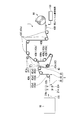
- the figure which shows schematic structure of a film manufacturing apparatus and shows the state conveyed by the 1st film conveyance path
- the figure which shows schematic structure of a film manufacturing apparatus and shows the state conveyed by the 2nd film conveyance path
- FIGS. 1 and 2 are schematic configuration diagrams of a film manufacturing apparatus according to an embodiment of the present invention.
- FIG. 1 shows a state in which a film is conveyed by a first film conveyance path
- route is shown.
- the film manufacturing apparatus 1 is a film manufacturing unit 10 for manufacturing a predetermined film 100 and a predetermined defect inspection of the film 100 manufactured by the film manufacturing unit 10.
- a defect inspection unit 5 and a control unit 50 are provided.
- each component of the film manufacturing apparatus 1 is comprehensively controlled by the said control part 50 as an electronic control apparatus.
- the defect inspection unit 5 is constituted by a defect inspection system according to an embodiment of the present invention.
- the defect inspection unit 5 includes a defect inspection unit 20, a recording unit 30 capable of recording defect information related to defects detected by the defect inspection unit 20 on both sides of the film 100, a film manufacturing unit 10, a defect inspection unit 20, and And a film transport unit 40 that sequentially transports the film 100 between the recording units 30.
- the film transport section 40 can transport the film 100 manufactured by the film manufacturing unit 10 via the first film transport path 40A or the second film transport path 40B. Switching of the first film transport path 40A or the second film transport path 40B in the film transport unit 40 is performed by an operator's work.
- the recording unit 30 when the film 100 conveyed via the first film conveyance path 40A reaches the recording unit 30, one side (first surface) 100b side faces the recording unit 30.
- the film 100 conveyed via the second film conveyance path 40 ⁇ / b> B reaches the recording unit 30 the other surface (second surface) 100 c side faces the recording unit 30. That is, when the first film transport path 40A is selected in the film transport unit 40, the recording unit 30 can record defect information on the one surface 100b side of the film 100, and the second film transport in the film transport unit 40. When the path 40B is selected, the recording unit 30 can record defect information on the other surface 100c side of the film 100.
- the one surface 100b of the film 100 is a surface on the side where the first protection film 100B is bonded in the film 100 manufactured by the film manufacturing unit 10 as described later, and the other surface 100c of the film 100 These are the surfaces on the side where the second protection film 100C is bonded (see FIG. 3).
- the defect inspection unit 20 detects defects in the film 100 by executing inspection processing such as reflection inspection, transmission inspection, oblique transmission inspection, and crossed Nicol transmission inspection on the film 100 being conveyed.
- the installation position of the defect inspection unit 20 is not limited to the place shown in FIG. 1, and may be any position as long as it is between the film manufacturing unit 10 and the recording unit 30 in the transport path of the film 100. .
- the defect inspection unit 20 is a defect in the film 100 of the illumination units 21 a and 22 a that irradiate the film 100 with light, and the light that is irradiated from the illumination units 21 a and 22 a and passes through the film 100 (one or both of reflection and transmission). And photodetectors 21b and 22b capable of detecting changes due to the presence or absence of the light.
- the defect inspection unit 20 includes an illumination unit and a photodetector for each type of defect to be inspected.
- the illumination units 21a and 22a irradiate light whose light intensity, wavelength, polarization state, etc. are adjusted according to the type of inspection performed by the defect inspection unit 20.
- the photodetectors 21b and 22b are configured by an image pickup device such as a CCD, and pick up an image of a portion of the film 100 irradiated with light by the illumination units 21a and 22a.
- the detection results (imaging results) of the photodetectors 21b and 22b are output to the control unit 50.
- the film transport unit 40 causes the film 100 to be defective so that the other surface 100c faces the photodetectors 21b and 22b in both the first film transport path 40A and the second film transport path 40B. It is conveyed to the inspection unit 20.
- the control unit 50 analyzes the images captured by the photodetectors 21b and 22b, and determines the position and type of the defect. When it is determined that the film 100 has a defect, the control unit 50 controls the recording unit 30 to record defect information on the film 100 as described later.
- control unit 50 is configured to include a computer system.
- This computer system includes an arithmetic processing unit such as a CPU and a storage unit such as a memory and a hard disk.
- the control unit 50 of the present embodiment includes an interface that can execute communication with an external device of the computer system.
- An input device that can input an input signal may be connected to the control unit 50.
- the input device includes an input device such as a keyboard and a mouse, or a communication device that can input data from a device external to the computer system.
- the control unit 50 may include a display device such as a liquid crystal display that indicates the operation status of each unit of the film manufacturing apparatus 1 or may be connected to the display device.
- An operating system (OS) that controls the computer system is installed in the storage unit of the control unit 50.
- the storage unit of the control unit 50 stores a program that causes the arithmetic processing unit to control each unit of the film manufacturing apparatus 1 to execute processing for causing each unit of the film manufacturing apparatus 1 to accurately transport the film 100. Yes.
- Various types of information including programs recorded in the storage unit can be read by the arithmetic processing unit of the control unit 50.
- the control unit 50 may include a logic circuit such as ASIC (Application Specific Integrated ⁇ ⁇ Circuit) that executes various processes required for controlling each part of the film manufacturing apparatus 1.
- ASIC Application Specific Integrated ⁇ ⁇ Circuit
- the storage unit is a concept including a semiconductor memory such as a RAM (Random Access Memory) and a ROM (Read Only Memory), and an external storage device such as a hard disk, a CD-ROM reader, and a disk-type storage medium.
- the storage unit is functionally a storage area for storing program software in which the control procedure of operations of the film manufacturing unit 10, the defect inspection unit 20, the recording unit 30, and the film transport unit 40 is described, and various other storage areas Is set.
- the recording unit 30 is provided on the downstream side in the transport direction from the defect inspection unit 20 in the first film transport path 40A or the second film transport path 40B in which the film 100 is transported.
- the recording unit 30 displays defect information relating to defects detected by the defect inspection unit 20 on one side 100b (the side on which the first protection film 100B is bonded) or the other side 100c (second protection film 100C) of the film 100. On the side where the is bonded).
- the defect information includes information on the position and type of the defect.
- the recording unit 30 records defect information on the film 100 at a predetermined timing after the defect inspection is performed by the defect inspection unit 20.
- the timing at which recording is performed by the recording unit 30 is determined by the transport distance of the film 100 from the defect inspection unit 20 to the recording unit 30. For example, when a rotary encoder that measures the transport amount of the film 100 is disposed on the transport path of the film 100 and the transport amount of the film 100 (the number of pulses counted by the rotary encoder) reaches a predetermined value.
- the control unit 50 controls the recording unit 30 to record defect information on the film 100.
- the recording unit 30 is, for example, an end of the surface (one surface 100b and the other surface 100c) of the film 100 in the form of defect information in the form of identification codes (one-dimensional barcode, two-dimensional barcode, QR code (registered trademark), etc.) To record.
- the identification code includes, for example, information (defects) indicating how far the defect detected by the defect inspection unit 20 is located along the film width direction from the position where the barcode is attached. Information on the location of the).
- the identification code may include information regarding the type of detected defect.
- the recording unit 30 directly displays the position of the defect on the surface of the film 100 (marking) by attaching a dot-shaped, line-shaped, or frame-shaped mark that includes the defect to the defective portion of the film 100. May be. At this time, information on the type of the result may be recorded by showing a symbol or pattern indicating the type of the defect together with the mark in the defective part. Moreover, the structure which affixes the label which attached
- the film transport unit 40 includes a first transport roller unit 43, a second transport roller unit 45, and a film winding unit 44.
- the first transport roller unit 43 has a case where defect information is recorded on one surface (first surface) 100 b of the film 100 by the recording unit 30 (first mode) and the other surface (first surface). 2 side)
- the defect information is recorded on 100c (second mode)
- the film 100 is wound. That is, the first transport roller unit 43 is configured to wind the film 100 when any one of the first film transport path 40A and the second film transport path 40B is selected in the film transport unit 40.
- the first transport roller section 43 is used in the first film transport path 40A and the second film transport path 40B, unlike the second transport roller section 45 described later.
- the second transport roller unit 45 When the defect information is recorded on one surface (first surface) 100b of the film 100 by the recording unit 30 (first mode), the second transport roller unit 45 records defect information on the other surface (second surface) 100c.
- the film 100 is wound in one of the modes (second mode). That is, the second transport roller unit 45 changes the winding method of the film 100 in response to the switching of the path between the first film transport path 40A and the second film transport path 40B in the film transport unit 40. Is.
- the second transport roller unit 45 is not used in the first film transport path 40A and the second film transport path 40B.
- the second transport roller unit 45 includes a one-side recording roller unit 41 and a second-side recording roller unit 42.
- the one-side recording roller unit 41 is a portion around which the film 100 is wound when the recording unit 30 records the defect information on the one side 100b of the film 100. That is, the one-side recording roller unit 41 is the one on which the film 100 is wound when the first film transport path 40A is selected.
- the other side recording roller portion 42 is a portion around which the film 100 is wound when the recording unit 30 records the defect information on the other side 100 c of the film 100. That is, the other-side recording roller unit 42 is configured to wind the film 100 when the second film transport path 40B is selected in the film transport unit 40.
- the one-side recording roller unit 41 includes a plurality (two in the present embodiment) of rollers 41a.
- the arrows shown along the outer periphery of each roller 41a indicate the rotation direction of the roller 41a.
- the roller 41a may be composed of a driven roller that is rotated by the transport force of the film 100, may be composed of a main roller that imparts a transport force to the film 100, or is composed of these in a mixed manner. May be.
- the number of rollers 41a is not limited to the above two, and may include one or three or more rollers 41a.
- the other-side recording roller unit 42 is composed of one roller 42a.
- the arrows shown along the outer periphery of the roller 42a indicate the rotation direction of the roller 42a.
- the roller 42a may be constituted by a driven roller that rotates by the conveyance force of the film 100, may be constituted by a main driving roller that imparts conveyance force to the film 100, or is constituted by mixing these. May be.
- the number of rollers 42a is not limited to one, and may include a plurality of rollers 42a.
- the first transport roller unit 43 includes a front stage part 43A, a middle stage part 43B, and a rear stage part 43C.
- the front-stage part 43A, the middle-stage part 43B, and the rear-stage part 43C are each composed of a plurality of rollers.
- the front stage portion 43A is configured by a plurality (three in the case of this embodiment) of rollers 43a
- the middle stage portion 43B is configured by a plurality of (three in the case of this embodiment) rollers 43b
- 43C includes a plurality of (four in the case of this embodiment) rollers 43c.
- these rollers 43a, 43b, and 43c may be comprised from the driven roller which rotates with the conveyance force of the film 100, may be comprised from the driving roller which provides the conveyance force to the film 100, and these. May be mixed. Further, in the front stage part 43A, the middle stage part 43B, and the rear stage part 43C, the number of the rollers 43a, 43b, 43c is not limited to the above, and can be changed as appropriate.
- rollers 43a, 43b, and 43c indicate the rotation directions of the rollers 43a, 43b, and 43c.
- the rollers 43b constituting the middle stage 43B are referred to as rollers 43b1, 43b2, and 43b3 in the order arranged from the upper side to the lower side of the figure for convenience and constitute the front stage 43A.
- the rollers 43a are referred to as rollers 43a1, 43a2, and 43a3 in the order in which they are disposed from the upstream side toward the downstream side in the transport direction of the film 100 in the figure.
- the film 100 drawn out from the film manufacturing unit 10 is composed of the front stage portion 43A (roller 43a), the one-side recording roller portion 41 (roller) from the upstream side toward the downstream side in the transport direction. 41a), the middle step portion 43B (roller 43b), and the rear step portion 43C (roller 43c).
- the film 100 is passed along the common inscribed line direction of the rollers 43a2 and 43a3 constituting the front stage 43A, and then drawn upward via the rollers 43a3. It is wound around the one-side recording roller unit 41.
- the film 100 that has passed through the one-side recording roller unit 41 is wound around the rollers 43b1, 43b2, and 43b3 of the middle stage 43B in this order.
- all the rollers 43b1, 43b2, 43b3 rotate counterclockwise, only the roller 43a2 of the front stage 43A rotates clockwise, and the rollers 43a1, 43a3 counteract respectively. Rotate clockwise.
- the film 100 passes through the recording unit 30 so as to go from the upper side to the lower side in the vertical direction through the one-side recording roller unit 41. At this time, the film 100 is conveyed so that the one surface 100b faces the recording unit 30. Therefore, the recording unit 30 can record defect information on the one surface 100b of the film 100 conveyed via the first film conveyance path 40A.
- the film 100 that has passed through the roller 43b3 of the middle step portion 43B is folded back upward in the vertical direction, and is then wound around the film winding portion 44 via the rear step portion 43C (roller 43c).
- the film 100 drawn out from the film manufacturing unit 10 is composed of the front stage portion 43A (roller 43a) and the other side recording roller portion 42 (roller) from the upstream side toward the downstream side in the transport direction. 42a), the middle step portion 43B (roller 43b), and the rear step portion 43C (roller 43c) are wound in this order.
- the film 100 is stretched along the common outer tangent direction of the rollers 43a2 and 43a3 constituting the front stage 43A, the film 100 is drawn downward via the roller 43a3 so as to reach the other-side recording roller 42. Wrapped. As shown in FIG. 2, only the roller 43a1 of the front stage 43A rotates counterclockwise, and the rollers 43a2 and 43a3 rotate clockwise.
- the film 100 that has passed through the other-side recording roller portion 42 is wound around the rollers 43b3, 43b2, and 43b1 of the middle portion 43B in this order.
- the rollers 43b1 and 43b2 rotate clockwise
- the roller 43b3 rotates counterclockwise.
- the film 100 passes through the recording unit 30 so as to go from the lower side in the vertical direction to the upper side through the other side recording roller unit 42. At this time, the film 100 is conveyed so that the other surface 100 c faces the recording unit 30. Therefore, the recording unit 30 can record defect information on the other surface 100c of the film 100 conveyed via the second film conveyance path 40B.
- the film 100 that has passed through the roller 43b1 of the middle stage portion 43B is wound around the film winding portion 44 through the rear stage portion 43C (roller 43c).
- one of the film transport paths in the first transport roller unit 43 is selected when the first film transport path 40A is selected and when the second film transport path 40B is selected.
- the conveyance direction of the film 100 is switched at the part.
- the first transport roller unit 43 includes the roller 43a3 and the middle stage 43B of the front stage 43A when the second film transport path 40B is selected and when the first film transport path 40A is selected.
- the rotation directions of the rollers 43b1 and 43b2 are switched.
- the rotation direction of the rollers 43a3, 43b1, and 43b2 may be switched only by driving the film winding unit 44 when, for example, each of these rollers is constituted by a driven roller.
- a rotation driving unit (not shown) that rotates each of the rollers in accordance with the selection by the selection of the first and second film transport paths 40A and 40B. It is only necessary to switch the rotation direction.
- the film transport unit 40 is arranged on one side so that the distance between the defect inspection unit 20 and the recording unit 30 in the first film transport path 40A and the second film transport path 40B is equal.
- a recording roller unit 41, the other side recording roller unit 42, and a first transport roller unit 43 are provided. That is, the arrangement position, pitch, and the like between the rollers 41a, 42a, 43a, 43b, and 43c constituting the one-side recording roller unit 41, the other-side recording roller unit 42, and the first transport roller unit 43 are the above conditions. Optimized to meet.
- the defect inspection unit 20 when the film transport unit 40 records defect information on the one surface 100b in the first film transport path 40A and when it records defect information on the other surface 100c in the second film transport path 40B, the defect inspection unit 20 Thus, the time from when the defect inspection is performed until the recording of the defect information by the recording unit 30 (timing of recording the defect information by the recording unit 30) can be made the same. Therefore, it is possible to eliminate the trouble of adjusting the recording timing by the recording unit 30 in accordance with the switching between the first film transport path 40A and the second film transport path 40B. Therefore, the defect information can be accurately recorded at the predetermined position at the timing when the predetermined position of the film 100 where the defect information is detected by the defect inspection unit 20 reaches the recording unit 30.
- FIG. 3 is a diagram showing a schematic configuration of the film manufacturing unit 10.
- the film manufacturing unit 10 manufactures the said film 100 by bonding the protection films (surface protection film) 100B and 100C to the film base material 100A.
- the film base material 100A and the protection films 100B and 100C may be any strip-like film having flexibility, and the material and configuration thereof are not particularly limited.
- the protection films 100B and 100C may be referred to as a first protection film 100B and a second protection film 100C, respectively.
- the film manufacturing unit 10 includes a first line 11, a second line 12, a third line 13, a fourth line 14, and a fifth line 15.
- the second line 12, the third line 13, and the fifth line 15 constitute a transport line for the first protection film 100B.
- the fourth line 14 and the fifth line 15 constitute a transport line for the second protection film 100C.
- the first line 11, the third line 13, and the fifth line 15 constitute a transport line for the film substrate 100 ⁇ / b> A.
- a plurality of rolls for example, a guide roll 31 and a nip roll 33 in the present embodiment
- a transport path for the film base 100A and the protection films 100B and 100C are provided. , 34, 35, 36).
- the first line 11 manufactures and transports the film substrate 100A.
- the film substrate 100A is a polarizing film, but the film substrate 100A is not limited thereto.
- a dyeing process, a crosslinking process, a stretching process, and the like are performed on a PVA (Polyvinyl Alcohol) film that is a base material of a polarizer.
- a film protective substrate 100A is manufactured by pasting a polarizer protective film made of TAC (Triacetylcellulose) or the like on both sides thereof.
- TAC Triacetylcellulose
- the film substrate 100A is not limited to a polarizing film, but may be other films such as a retardation film, a light diffusion film, a light reflecting film, a lens film, a conductive film, an insulating film, and a photosensitive film.
- the 2nd line 12 unwinds and conveys the 1st protection film 100B from the 1st original fabric roll R1.
- the first protection film 100B is a PET (Polyethylene terephthalate) film, but the first protection film 100B is not limited to this.
- the third line 13 has a pair of nip rolls 33 and 34 arranged in parallel with each other in the axial direction.
- a predetermined gap is formed between the pair of nip rolls 33 and 34, and the inside of the gap is a bonding position between the film base 100A and the first protection film 100B.
- the film base 100A and the first protection film 100B are introduced in an overlapping manner.
- 100 A of film base materials and the 1st protection film 100B are sent out downstream while being pinched by the nip rolls 33 and 34. Thereby, the 1st protection film 100B is bonded by one side of 100A of film base materials.
- the 4th line 14 unwinds and conveys the 2nd protection film 100C from the 2nd original fabric roll R2.
- the second protection film 100C is a PET (Polyethylene terephthalate) film, but the second protection film 100C is not limited to this.
- 5th line 15 bonds the 2nd protection film 100C on the other side (surface opposite to the surface where the 1st protection film 100B was bonded) of film substrate 100A, and conveys it.
- the said film 100 is manufactured by bonding the 1st protection film 100B and the 2nd protection film 100C to one side and the other side of 100 A of film base materials.
- the fifth line 15 has a pair of nip rolls 35 and 36 that are arranged with their axial directions parallel to each other.
- a predetermined gap is formed between the pair of nip rolls 35 and 36, and the inside of the gap is a bonding position between the film base 100A and the second protection film 100C.
- the film base 100A and the second protection film 100C are overlapped and introduced.
- 100 A of film base materials and the 2nd protection film 100C are sent out downstream while being pinched by the nip rolls 35 and 36.
- FIG. Thereby, the second protection film 100C is bonded to the other surface of the film base 100A.
- the film manufacturing unit 10 can manufacture the film 100 by bonding the first protection film 100B and the second protection film 100C to both surfaces of the film base 100A.
- the operator changes the first film transport path 40 ⁇ / b> A or the second film transport path 40 ⁇ / b> B as the transport path of the film 100, so
- the defect information can be recorded on each of both the inspected and inspected defects (one side 100b and the other side 100c). Therefore, since it becomes possible to record defect information on both sides of the film 100 with only one recording unit 30, the installation space of the apparatus can be reduced compared to the case where two recording units are provided for double-sided recording as in the past.
- the defect inspection of the film can be performed at a low cost.
- the film 100 on which defect information is recorded can be manufactured at a low cost.
- the present invention is not limited to the example.
- Various shapes, combinations, and the like of the constituent members shown in the above-described examples are examples, and various modifications can be made based on design requirements and the like without departing from the gist of the present invention.
- the 1st line 11 of the said film manufacturing unit 10, 2nd A defect inspection unit may be provided in the middle of at least one of the line 12 and the fourth line 14. According to this, the defect inspection in 100 A of film base materials before the protection films 100B and 100C are bonded can be performed, and the precision improvement of the defect inspection in the film 100 is achieved.
- the configuration in which the defect inspection unit 5 is incorporated in the film manufacturing apparatus 1 that inspects the film 100 manufactured by the film manufacturing unit 10 is taken as an example. It can also function as a single inspection apparatus for inspecting defects of the film manufactured in the above.
- the defect inspection of the film is performed by conveying the film from the raw roll to be inspected to the recording unit 30 while being unwound by the film conveying unit 40 and recording predetermined defect information, and then the film winding unit 44. It ends by being wound up by.
- the film can be transported to another factory, and the defect inspection of the film can be performed using only the defect inspection unit 5 in the other factory.
- the 2nd conveyance roller part 45 included both the roller part 41 for one side recording and the roller part 42 for the other side recording was mentioned as an example, only one of them was included.
- a configuration may be adopted.
- the 2nd conveyance roller part 45 may be comprised only from the roller part 41 for one side recording.
- the film 100 passing through the second film transport path 40B where defect recording is performed on the other surface 100c is transported by being wound only on the first transport roller unit 43, and defect recording is performed on the one surface 100b.
- the film 100 passing through the first film transport path 40A is transported by being wound around the first transport roller unit 43 and the second transport roller unit 45 (one-side recording roller unit 41).
- the 2nd conveyance roller part 45 may be comprised only from the roller part 42 for recording on the other side.
- the film 100 passing through the second film transport path 40B where defect recording is performed on the other surface 100c is wound around the first transport roller unit 43 and the second transport roller unit 45 (the other surface recording roller unit 42).
- the film 100 that is transported and passes through the first film transport path 40 ⁇ / b> A where defect recording is performed on the one surface 100 b is transported by being wound only on the first transport roller unit 43.
Landscapes
- Engineering & Computer Science (AREA)
- Textile Engineering (AREA)
- Physics & Mathematics (AREA)
- Health & Medical Sciences (AREA)
- Life Sciences & Earth Sciences (AREA)
- Chemical & Material Sciences (AREA)
- Analytical Chemistry (AREA)
- Biochemistry (AREA)
- General Health & Medical Sciences (AREA)
- General Physics & Mathematics (AREA)
- Immunology (AREA)
- Pathology (AREA)
- Investigating Materials By The Use Of Optical Means Adapted For Particular Applications (AREA)
Abstract
Description
本願は、2013年8月2日に出願された日本国特願2013-161809号に基づき優先権を主張し、その内容をここに援用する。
(1)本発明に係る一態様の欠陥検査システムは、帯状のフィルムを搬送するフィルム搬送部と、前記フィルム搬送部により搬送される前記フィルムの欠陥検査を行う欠陥検査部と、前記フィルム搬送部が構成するフィルム搬送経路において前記欠陥検査部よりも下流側に設けられ、前記欠陥検査部によって検出された欠陥に関する欠陥情報を前記フィルムに記録可能な記録部と、を備え、前記フィルム搬送部は、前記記録部により前記フィルムの第1面に前記欠陥情報が記録される第1モード及び第2面に前記欠陥情報が記録される第2モードのそれぞれにおいて前記フィルムが巻き掛けられる第1搬送ローラー部と、前記第1モード及び前記第2モードのいずれか一方において前記フィルムが巻き掛けられる第2搬送ローラー部と、を含む。
図1、2に示すように、フィルム製造装置1は、所定のフィルム100を製造するためのフィルム製造ユニット10と、該フィルム製造ユニット10で製造されたフィルム100の所定の欠陥検査を行うための欠陥検査ユニット5と、制御部50と、を備えている。
なお、フィルム製造装置1の各構成要素は、電子制御装置としての上記制御部50により統括制御される。上記欠陥検査ユニット5は、本発明の一実施形態に係る欠陥検査システムにより構成されるものである。
このコンピュータシステムは、CPU等の演算処理部と、メモリやハードディスク等の記憶部とを備える。本実施形態の制御部50は、コンピュータシステムの外部の装置との通信を実行可能なインターフェースを含む。制御部50には、入力信号を入力可能な入力装置が接続されていてもよい。上記の入力装置は、キーボード、マウス等の入力機器、あるいはコンピュータシステムの外部の装置からのデータを入力可能な通信装置等を含む。制御部50は、フィルム製造装置1の各部の動作状況を示す液晶表示ディスプレイ等の表示装置を含んでいてもよいし、表示装置と接続されていてもよい。
例えば、フィルム100の搬送経路上に、フィルム100の搬送量を測定するロータリーエンコーダが配置され、フィルム100の搬送量(ロータリーエンコーダによってカウントされるパルスのカウント数)が所定の値に達したときに制御部50が記録部30を制御して、フィルム100に欠陥情報を記録するようになっている。
また、記録部30は、上記マーキングを付したラベルをフィルム100の表面に貼付する構成であってもよい。
一方面記録用ローラー部41は、記録部30によりフィルム100の一方面100bに上記欠陥情報が記録される場合に該フィルム100が巻き掛けられるものである。すなわち、一方面記録用ローラー部41は、上記第1フィルム搬送経路40Aが選択された場合において、フィルム100が巻き掛けられるものである。
ローラー42aは、フィルム100の搬送力によって回転する従動ローラーから構成されていてもよいし、フィルム100に搬送力を付与する主動ローラーから構成されていてもよいし、これらが混在して構成されていてもよい。なお、他方面記録用ローラー部42において、ローラー42aの数は1つに限定されることはなく、複数のローラー42aを有していてもよい。
この場合、フィルム製造ユニット10から引き出されたフィルム100は、図1に示すように、搬送方向上流側から下流側に向かって上記前段部43A(ローラー43a)、一方面記録用ローラー部41(ローラー41a)、中段部43B(ローラー43b)、及び後段部43C(ローラー43c)の順に巻き掛けられる。
この場合、フィルム製造ユニット10から引き出されたフィルム100は、図2に示すように、搬送方向上流側から下流側に向かって上記前段部43A(ローラー43a)、他方面記録用ローラー部42(ローラー42a)、中段部43B(ローラー43b)、及び後段部43C(ローラー43c)の順に巻き掛けられる。
その後、その両面にTAC(Triacetylcellulose)などからなる偏光子保護フィルムを貼合することによりフィルム基材100Aを製造する。なお、フィルム基材100Aは、偏光フィルムに限らず、位相差フィルム、光拡散フィルム、光反射フィルム、レンズフィルム、導電フィルム、絶縁フィルム、感光性フィルムなどの他のフィルムでもよい。
このようにして、フィルム製造ユニット10は、フィルム基材100Aの両面に第1プロテクションフィルム100Bおよび第2プロテクションフィルム100Cを貼合することでフィルム100を製造することができる。
よって、1つの記録部30のみでフィルム100の両面に欠陥情報を記録することが可能となるため、従来のように両面記録用に記録部を2つ備える場合に比べ、装置の設置スペースを抑えつつ、低コストでフィルムの欠陥検査を行うことができる。また、低コストで欠陥情報が記録されたフィルム100を製造することができる。
Claims (6)
- 帯状のフィルムを搬送するフィルム搬送部と、
前記フィルム搬送部により搬送される前記フィルムの欠陥検査を行う欠陥検査部と、
前記フィルム搬送部が構成するフィルム搬送経路において前記欠陥検査部よりも下流側に設けられ、前記欠陥検査部によって検出された欠陥に関する欠陥情報を前記フィルムに記録可能な記録部と、を備え、
前記フィルム搬送部は、
前記記録部により前記フィルムの第1面に前記欠陥情報が記録される第1モード及び第2面に前記欠陥情報が記録される第2モードのそれぞれにおいて前記フィルムが巻き掛けられる第1搬送ローラー部と、
前記第1モード及び前記第2モードのいずれか一方において前記フィルムが巻き掛けられる第2搬送ローラー部と、を含む
欠陥検査システム。 - 前記第1搬送ローラー部は、前記第1モードと前記第2モードとの切り替えに対応して、前記フィルム搬送経路の一部における前記フィルムの搬送方向を切り替える
請求項1に記載の欠陥検査システム。 - 前記フィルム搬送部は、前記第1モードにおいて前記フィルムを第1フィルム搬送経路で搬送し、前記第2モードにおいて前記フィルムを第2フィルム搬送経路で搬送しており、前記第1フィルム搬送経路及び前記第2フィルム搬送経路のうち前記欠陥検査部と前記記録部との間における距離がそれぞれ等しくなるように、前記第1搬送ローラー部、及び第2搬送ローラー部が設置される
請求項1又は2に記載の欠陥検査システム。 - 前記記録部は、前記第1搬送ローラー部に巻き掛けられる前記フィルムに前記欠陥情報を記録する
請求項1~3のいずれか一項に記載の欠陥検査システム。 - 前記第1搬送ローラー部、及び第2搬送ローラー部の少なくとも一方は、複数のローラー部材を含む
請求項1~4のいずれか一項に記載の欠陥検査システム。 - 帯状のフィルムを製造するフィルム製造ユニットと、
前記フィルム製造ユニットにより製造された前記フィルムの欠陥検査を行う欠陥検査ユニットと、を備え、
前記欠陥検査ユニットとして、請求項1~5のいずれか一項に記載の欠陥検査システムを有するフィルム製造装置。
Priority Applications (2)
| Application Number | Priority Date | Filing Date | Title |
|---|---|---|---|
| KR1020167002619A KR102241700B1 (ko) | 2013-08-02 | 2014-07-31 | 결함 검사 시스템 및 필름 제조 장치 |
| CN201480042672.7A CN105408737B (zh) | 2013-08-02 | 2014-07-31 | 缺陷检查系统以及膜制造装置 |
Applications Claiming Priority (2)
| Application Number | Priority Date | Filing Date | Title |
|---|---|---|---|
| JP2013161809A JP6410413B2 (ja) | 2013-08-02 | 2013-08-02 | 欠陥検査システム及びフィルム製造装置 |
| JP2013-161809 | 2013-08-02 |
Publications (1)
| Publication Number | Publication Date |
|---|---|
| WO2015016299A1 true WO2015016299A1 (ja) | 2015-02-05 |
Family
ID=52431826
Family Applications (1)
| Application Number | Title | Priority Date | Filing Date |
|---|---|---|---|
| PCT/JP2014/070166 Ceased WO2015016299A1 (ja) | 2013-08-02 | 2014-07-31 | 欠陥検査システム及びフィルム製造装置 |
Country Status (5)
| Country | Link |
|---|---|
| JP (1) | JP6410413B2 (ja) |
| KR (1) | KR102241700B1 (ja) |
| CN (1) | CN105408737B (ja) |
| TW (1) | TWI630381B (ja) |
| WO (1) | WO2015016299A1 (ja) |
Families Citing this family (5)
| Publication number | Priority date | Publication date | Assignee | Title |
|---|---|---|---|---|
| CN105291562B (zh) * | 2015-11-02 | 2018-05-11 | 江苏顺泰包装印刷科技有限公司 | 一种用于高速凹印机的印刷缺陷标识装置及其工作方法 |
| CN106353335A (zh) * | 2016-08-11 | 2017-01-25 | 苏州柯创电子材料有限公司 | 一种用于包装膜的表面缺陷检测装置 |
| KR102469408B1 (ko) * | 2017-03-03 | 2022-11-22 | 스미또모 가가꾸 가부시키가이샤 | 결함 검사 시스템, 필름 제조 장치, 필름 제조 방법, 인자 장치 및 인자 방법 |
| JP6934733B2 (ja) * | 2017-03-03 | 2021-09-15 | 住友化学株式会社 | マーキング装置、欠陥検査システム及びフィルム製造方法 |
| KR102438892B1 (ko) * | 2017-03-03 | 2022-08-31 | 스미또모 가가꾸 가부시키가이샤 | 결함 검사 시스템, 필름 제조 장치, 필름 제조 방법, 인자 장치 및 인자 방법 |
Citations (6)
| Publication number | Priority date | Publication date | Assignee | Title |
|---|---|---|---|---|
| JP2000177895A (ja) * | 1998-12-15 | 2000-06-27 | Hitachi Ltd | 両面記録装置 |
| JP2001328754A (ja) * | 2000-05-18 | 2001-11-27 | Oki Electric Ind Co Ltd | 印刷装置 |
| JP2004177143A (ja) * | 2002-11-25 | 2004-06-24 | Purex:Kk | 欠陥布類検出装置 |
| JP2004184299A (ja) * | 2002-12-05 | 2004-07-02 | Fuji Photo Film Co Ltd | 欠陥検出表示システムおよび欠陥検出表示方法 |
| JP2010041430A (ja) * | 2008-08-05 | 2010-02-18 | Fuji Xerox Co Ltd | 画像形成装置 |
| JP2012045770A (ja) * | 2010-08-25 | 2012-03-08 | Canon Inc | 記録装置 |
Family Cites Families (5)
| Publication number | Priority date | Publication date | Assignee | Title |
|---|---|---|---|---|
| JP4960161B2 (ja) * | 2006-10-11 | 2012-06-27 | 日東電工株式会社 | 検査データ処理装置及び検査データ処理方法 |
| JP2008247526A (ja) * | 2007-03-29 | 2008-10-16 | Fujifilm Corp | ウェブ加工ライン |
| JP2009053122A (ja) * | 2007-08-28 | 2009-03-12 | Panasonic Electric Works Co Ltd | 透明フィルム外観検査システム |
| JP5588223B2 (ja) | 2009-05-26 | 2014-09-10 | 旭化成イーマテリアルズ株式会社 | ワイヤグリッド偏光フィルム用欠陥マーキング装置及び欠陥マーキング方法 |
| CN202330297U (zh) * | 2011-11-28 | 2012-07-11 | 陕西长岭纺织机电科技有限公司 | 自动检测织物疵点的装置 |
-
2013
- 2013-08-02 JP JP2013161809A patent/JP6410413B2/ja active Active
-
2014
- 2014-07-31 KR KR1020167002619A patent/KR102241700B1/ko active Active
- 2014-07-31 CN CN201480042672.7A patent/CN105408737B/zh active Active
- 2014-07-31 TW TW103126152A patent/TWI630381B/zh active
- 2014-07-31 WO PCT/JP2014/070166 patent/WO2015016299A1/ja not_active Ceased
Patent Citations (6)
| Publication number | Priority date | Publication date | Assignee | Title |
|---|---|---|---|---|
| JP2000177895A (ja) * | 1998-12-15 | 2000-06-27 | Hitachi Ltd | 両面記録装置 |
| JP2001328754A (ja) * | 2000-05-18 | 2001-11-27 | Oki Electric Ind Co Ltd | 印刷装置 |
| JP2004177143A (ja) * | 2002-11-25 | 2004-06-24 | Purex:Kk | 欠陥布類検出装置 |
| JP2004184299A (ja) * | 2002-12-05 | 2004-07-02 | Fuji Photo Film Co Ltd | 欠陥検出表示システムおよび欠陥検出表示方法 |
| JP2010041430A (ja) * | 2008-08-05 | 2010-02-18 | Fuji Xerox Co Ltd | 画像形成装置 |
| JP2012045770A (ja) * | 2010-08-25 | 2012-03-08 | Canon Inc | 記録装置 |
Also Published As
| Publication number | Publication date |
|---|---|
| KR20160040544A (ko) | 2016-04-14 |
| CN105408737B (zh) | 2018-12-07 |
| JP6410413B2 (ja) | 2018-10-24 |
| KR102241700B1 (ko) | 2021-04-19 |
| TW201506385A (zh) | 2015-02-16 |
| TWI630381B (zh) | 2018-07-21 |
| JP2015031612A (ja) | 2015-02-16 |
| CN105408737A (zh) | 2016-03-16 |
Similar Documents
| Publication | Publication Date | Title |
|---|---|---|
| JP4406043B2 (ja) | ロール原反セット、及びロール原反の製造方法 | |
| JP6177017B2 (ja) | 欠陥検査システム | |
| JP4568375B2 (ja) | 光学表示装置の製造方法及び製造システム | |
| KR102222973B1 (ko) | 결함 검사 장치, 광학 부재의 제조 시스템 및 광학 표시 장치의 생산 시스템 | |
| JP6182806B2 (ja) | 欠陥検査システム及びフィルムの製造装置 | |
| JP6410413B2 (ja) | 欠陥検査システム及びフィルム製造装置 | |
| JP7086642B2 (ja) | 欠陥検査システム、フィルム製造装置、フィルム製造方法、印字装置及び印字方法 | |
| JP6978963B2 (ja) | 欠陥マーキング方法及び欠陥マーキング装置、原反の製造方法及び原反、並びにシートの製造方法及びシート | |
| JP6285658B2 (ja) | 欠陥検査システム及びフィルム製造装置 | |
| JP6204697B2 (ja) | 欠陥検査システム | |
| JP2018136342A (ja) | 欠陥検査システム及びフィルム製造装置 | |
| JP7195042B2 (ja) | 欠陥情報読取方法、欠陥情報読取システム及びフィルム製造装置 | |
| JP6116003B2 (ja) | 搬送装置 | |
| KR102438892B1 (ko) | 결함 검사 시스템, 필름 제조 장치, 필름 제조 방법, 인자 장치 및 인자 방법 |
Legal Events
| Date | Code | Title | Description |
|---|---|---|---|
| WWE | Wipo information: entry into national phase |
Ref document number: 201480042672.7 Country of ref document: CN |
|
| 121 | Ep: the epo has been informed by wipo that ep was designated in this application |
Ref document number: 14832289 Country of ref document: EP Kind code of ref document: A1 |
|
| ENP | Entry into the national phase |
Ref document number: 20167002619 Country of ref document: KR Kind code of ref document: A |
|
| NENP | Non-entry into the national phase |
Ref country code: DE |
|
| 122 | Ep: pct application non-entry in european phase |
Ref document number: 14832289 Country of ref document: EP Kind code of ref document: A1 |