WO2015016091A1 - 照明装置及び表示装置 - Google Patents
照明装置及び表示装置 Download PDFInfo
- Publication number
- WO2015016091A1 WO2015016091A1 PCT/JP2014/069227 JP2014069227W WO2015016091A1 WO 2015016091 A1 WO2015016091 A1 WO 2015016091A1 JP 2014069227 W JP2014069227 W JP 2014069227W WO 2015016091 A1 WO2015016091 A1 WO 2015016091A1
- Authority
- WO
- WIPO (PCT)
- Prior art keywords
- light guide
- light
- guide plates
- guide plate
- incident
- Prior art date
- Legal status (The legal status is an assumption and is not a legal conclusion. Google has not performed a legal analysis and makes no representation as to the accuracy of the status listed.)
- Ceased
Links
Images




Classifications
-
- G—PHYSICS
- G02—OPTICS
- G02B—OPTICAL ELEMENTS, SYSTEMS OR APPARATUS
- G02B6/00—Light guides; Structural details of arrangements comprising light guides and other optical elements, e.g. couplings
- G02B6/0001—Light guides; Structural details of arrangements comprising light guides and other optical elements, e.g. couplings specially adapted for lighting devices or systems
- G02B6/0011—Light guides; Structural details of arrangements comprising light guides and other optical elements, e.g. couplings specially adapted for lighting devices or systems the light guides being planar or of plate-like form
- G02B6/0075—Arrangements of multiple light guides
- G02B6/0078—Side-by-side arrangements, e.g. for large area displays
-
- F—MECHANICAL ENGINEERING; LIGHTING; HEATING; WEAPONS; BLASTING
- F21—LIGHTING
- F21S—NON-PORTABLE LIGHTING DEVICES; SYSTEMS THEREOF; VEHICLE LIGHTING DEVICES SPECIALLY ADAPTED FOR VEHICLE EXTERIORS
- F21S2/00—Systems of lighting devices, not provided for in main groups F21S4/00 - F21S10/00 or F21S19/00, e.g. of modular construction
-
- G—PHYSICS
- G02—OPTICS
- G02B—OPTICAL ELEMENTS, SYSTEMS OR APPARATUS
- G02B6/00—Light guides; Structural details of arrangements comprising light guides and other optical elements, e.g. couplings
-
- G—PHYSICS
- G02—OPTICS
- G02B—OPTICAL ELEMENTS, SYSTEMS OR APPARATUS
- G02B6/00—Light guides; Structural details of arrangements comprising light guides and other optical elements, e.g. couplings
- G02B6/0001—Light guides; Structural details of arrangements comprising light guides and other optical elements, e.g. couplings specially adapted for lighting devices or systems
- G02B6/0011—Light guides; Structural details of arrangements comprising light guides and other optical elements, e.g. couplings specially adapted for lighting devices or systems the light guides being planar or of plate-like form
-
- G—PHYSICS
- G02—OPTICS
- G02B—OPTICAL ELEMENTS, SYSTEMS OR APPARATUS
- G02B6/00—Light guides; Structural details of arrangements comprising light guides and other optical elements, e.g. couplings
- G02B6/0001—Light guides; Structural details of arrangements comprising light guides and other optical elements, e.g. couplings specially adapted for lighting devices or systems
- G02B6/0011—Light guides; Structural details of arrangements comprising light guides and other optical elements, e.g. couplings specially adapted for lighting devices or systems the light guides being planar or of plate-like form
- G02B6/0075—Arrangements of multiple light guides
- G02B6/0078—Side-by-side arrangements, e.g. for large area displays
- G02B6/008—Side-by-side arrangements, e.g. for large area displays of the partially overlapping type
-
- G—PHYSICS
- G02—OPTICS
- G02B—OPTICAL ELEMENTS, SYSTEMS OR APPARATUS
- G02B6/00—Light guides; Structural details of arrangements comprising light guides and other optical elements, e.g. couplings
- G02B6/0001—Light guides; Structural details of arrangements comprising light guides and other optical elements, e.g. couplings specially adapted for lighting devices or systems
- G02B6/0011—Light guides; Structural details of arrangements comprising light guides and other optical elements, e.g. couplings specially adapted for lighting devices or systems the light guides being planar or of plate-like form
- G02B6/0081—Mechanical or electrical aspects of the light guide and light source in the lighting device peculiar to the adaptation to planar light guides, e.g. concerning packaging
- G02B6/0085—Means for removing heat created by the light source from the package
-
- G—PHYSICS
- G02—OPTICS
- G02B—OPTICAL ELEMENTS, SYSTEMS OR APPARATUS
- G02B6/00—Light guides; Structural details of arrangements comprising light guides and other optical elements, e.g. couplings
- G02B6/0001—Light guides; Structural details of arrangements comprising light guides and other optical elements, e.g. couplings specially adapted for lighting devices or systems
- G02B6/0011—Light guides; Structural details of arrangements comprising light guides and other optical elements, e.g. couplings specially adapted for lighting devices or systems the light guides being planar or of plate-like form
- G02B6/0081—Mechanical or electrical aspects of the light guide and light source in the lighting device peculiar to the adaptation to planar light guides, e.g. concerning packaging
- G02B6/0086—Positioning aspects
- G02B6/009—Positioning aspects of the light source in the package
-
- G—PHYSICS
- G02—OPTICS
- G02F—OPTICAL DEVICES OR ARRANGEMENTS FOR THE CONTROL OF LIGHT BY MODIFICATION OF THE OPTICAL PROPERTIES OF THE MEDIA OF THE ELEMENTS INVOLVED THEREIN; NON-LINEAR OPTICS; FREQUENCY-CHANGING OF LIGHT; OPTICAL LOGIC ELEMENTS; OPTICAL ANALOGUE/DIGITAL CONVERTERS
- G02F1/00—Devices or arrangements for the control of the intensity, colour, phase, polarisation or direction of light arriving from an independent light source, e.g. switching, gating or modulating; Non-linear optics
- G02F1/01—Devices or arrangements for the control of the intensity, colour, phase, polarisation or direction of light arriving from an independent light source, e.g. switching, gating or modulating; Non-linear optics for the control of the intensity, phase, polarisation or colour
- G02F1/13—Devices or arrangements for the control of the intensity, colour, phase, polarisation or direction of light arriving from an independent light source, e.g. switching, gating or modulating; Non-linear optics for the control of the intensity, phase, polarisation or colour based on liquid crystals, e.g. single liquid crystal display cells
- G02F1/133—Constructional arrangements; Operation of liquid crystal cells; Circuit arrangements
- G02F1/1333—Constructional arrangements; Manufacturing methods
- G02F1/1335—Structural association of cells with optical devices, e.g. polarisers or reflectors
- G02F1/1336—Illuminating devices
- G02F1/133615—Edge-illuminating devices, i.e. illuminating from the side
Definitions
- the present invention relates to an edge light type illumination device that emits light in a planar shape, and a display device using the illumination device as a backlight.
- a display device that displays an image using a non-light-emitting display panel such as a liquid crystal panel includes a backlight that illuminates the display panel from behind.
- Some backlights include an edge light type in which a light guide plate is disposed on the back side of the display panel and a light source is disposed in the vicinity of an end portion of the light guide plate.
- an edge light type backlight light from a light source enters an end of the light guide plate, diffuses in the light guide plate, and radiates from one plane of the light guide plate.
- a light emitting diode LED: Light Emitting Diode
- Patent Document 1 describes an illumination device that is used as a backlight of a display device having a large screen.
- the end of the light guide plate and the light source be as close as possible in order to increase the luminous efficiency.
- the light guide plate expands and contracts depending on the temperature or humidity, in the backlight where the end of the light guide plate and the light source are too close, the end of the light guide plate expanded at high temperature or high humidity collides with the light source. The light source may be destroyed. Further, the expanded light guide plate may be warped, and the warped light guide plate may push the display panel, causing unevenness of light on the display panel. For this reason, it is necessary to provide a certain distance between the light source and the light guide plate, and there is a problem that the light use efficiency is poor.
- the present invention has been made in view of such circumstances, and an object of the present invention is to provide an illuminating device and a display device capable of bringing the end of the light guide plate and the light source as close as possible. Is to provide.
- the size of the gap is larger than an amount in which the plurality of light guide plates expand in a direction along the light emitting surface in accordance with a change in temperature or humidity.
- the illuminating device is characterized in that the plurality of light guide plates are provided with a reflecting material that reflects internal light at portions facing each other in the end portions of the respective light guide plates.
- two light guide plates adjacent to each other among the plurality of light guide plates are inclined at an acute angle with respect to the light emitting surface at a portion facing each other in the end portion, and the other is It has an end face inclined at an obtuse angle, and a part of the end face mutually overlaps in the thickness direction.
- two adjacent light guide plates among the plurality of light guide plates have protrusions protruding at different positions in the thickness direction at portions facing each other in the end portions. Further, a part of the protruding portions of each other overlaps in the thickness direction.
- the display device includes a display panel for displaying an image and the illumination device according to the present invention for illuminating the display panel from one surface.
- an illumination device used as a backlight of a display device includes a plurality of light guide plates and a light source that makes light incident on an end of each light guide plate. There are gaps between the plurality of light guide plates, and the position of the portion of the light guide plate where light from the light source is incident is fixed.
- the light guide plate expands in response to a change in temperature or humidity, the end portion close to the light source does not move, and the light guide plates expand so as to approach each other.
- the size of the gap between the light guide plates is equal to or larger than the expansion amount of the light guide plate.
- the expansion amount of the light guide plate is absorbed by the gap.
- the two adjacent light guide plates have end faces that are inclined with respect to the light emitting surface at the end portions facing each other, and the end faces are partially spaced apart from each other in the thickness direction. Are overlapping. A portion where no light guide plate is present and light is not emitted in the front view is eliminated, and a partial decrease in the amount of light is suppressed.
- the present invention even when the light guide plate expands, the light guide plate does not collide with the light source, and the expansion amount of the light guide plate is absorbed by the gap between the light guide plates. For this reason, in an illuminating device, the arrangement
- FIG. 2 is an enlarged cross-sectional view of a part of the II-II cross section of FIG. 1.
- 1 is a schematic front view of a lighting device according to Embodiment 1.
- FIG. 6 is a schematic front view of a lighting apparatus according to Embodiment 2.
- FIG. 6 is a schematic front view of a lighting device according to Embodiment 3.
- FIG. 6 is a schematic front view of a lighting device according to Embodiment 4.
- FIG. 10 is a schematic front view of a lighting device according to Embodiment 5.
- 10 is a schematic cross-sectional view of a light guide plate according to Embodiment 6.
- FIG. 6 is a schematic front view of a light guide plate according to Embodiment 6.
- FIG. 1 is a front view of the display device.
- the display device is, for example, a television receiver.
- the display device includes a rectangular plate-like non-light emitting display panel 2 and a backlight.
- the backlight comprises the lighting device according to the present invention.
- the display panel 2 is illuminated from the rear side by a backlight and displays an image.
- the display panel 2 is a liquid crystal panel, for example.
- the peripheral edge of the display panel 2 is covered with the bezel 1.
- the bezel 1 is a frame-shaped metal member, and covers the peripheral portion and the side surface of the front surface of the display device.
- An optical sheet 4 for diffusing and condensing light from the backlight is disposed on the rear side of the first chassis 3.
- the optical sheet 4 is configured by laminating a plurality of sheets such as a sheet having a function of diffusing light from a backlight and a sheet having a function of collecting light, and allows light to pass therethrough.
- a light guide plate 5 is disposed on the rear side of the optical sheet 4, and a rectangular reflection sheet 6 is disposed on the rear side of the light guide plate 5.
- the light guide plate 5 receives light on its end surface and emits light with the front surface as a light emitting surface.
- the light emitted from the light guide plate 5 illuminates the display panel 2 from the rear side.
- a metal heat radiating plate 7 is arranged on the rear side of the reflection sheet 6.
- a part of the first chassis 3 is disposed on the front side of the peripheral portion of the optical sheet 4, and the heat radiating plate 7 is disposed on the rear side of the reflection sheet 6.
- the optical sheet 4, the light guide plate 5, and the reflection sheet 6 are sandwiched between the first chassis 3 and the heat radiating plate 7 with a spacer interposed therebetween.
- the optical sheet 4 may be disposed on the front side of the first chassis 3.
- FIG. 3 is a schematic front view of the lighting device 9 according to the first embodiment.
- the lighting device 9 includes two rectangular light guide plates 5 and 5 arranged in the long side direction of the display panel 2.
- the light emitting surfaces of the light guide plates 5 and 5 face the same direction.
- the light guide plates 5 and 5 have a shape in which a light guide plate having the same shape as the display panel 2 is divided in parallel to the short side at the center in the long side direction, and each light guide plate 5 is rectangular.
- the end portion of each light guide plate 5 is a rectangular side.
- One of the four end portions of the light guide plate 5 is a facing end portion 51 that faces the other light guide plate 5.
- An end of the light guide plate 5 that faces the facing end 51 is an incident end 52 on which light from the light source 8 is incident.
- the opposing end 51 and the incident end 52 are substantially parallel to the short side direction of the display panel 2.
- the light source 8 is disposed at a position close to the incident end 52 of each light guide plate 5. As shown in FIG. 2, the incident end 52 has an end surface that is substantially orthogonal to the light emitting surface, and the light source 8 is disposed opposite to the end surface.
- the light source 8 includes a plurality of LEDs arranged in a straight line along an incident end portion 52 that is a rectangular side. Light from the light source 8 enters the incident end portion 52 of the light guide plate 5, and the incident light diffuses in the light guide plate 5, and light is emitted from the light emitting surface of the light guide plate 5 toward the front surface.
- the light guide plate 5 expands in response to a change in temperature or humidity, the position of the incident end 52 of the light guide plate 5 is fixed, so that the incident end 52 does not collide with the light source 8. Therefore, there is no possibility that the light source 8 is destroyed at high temperature or high humidity.
- the position of the opposed end portion 51 is not fixed, the light guide plates 5 and 5 extend in a direction in which the opposed end portions 51 approach each other when expanded.
- the length of the gap 10 between the light guide plates 5 and 5 is equal to or greater than the total length of the opposing end portions 51 extending in a direction approaching each other when the light guide plates 5 and 5 expand according to changes in temperature or humidity. Yes.
- the light guide plates 5, 5 and the light sources 8, 8 are arranged with the light source 8 as close as possible to the incident end portion 52 of the light guide plate 5. Since the light source 8 is as close as possible to the incident end portion 52 of the light guide plate 5, the efficiency of light entering the light guide plate 5 from the light source 8 is high, and the light use efficiency for displaying an image on the display device is high. improves.
- the positions of the light guide plates 5 and 5 in the direction along the light emitting surface of the incident end 52 are fixed.
- a gap 10 is provided between the light guide plates 5 and 5.
- the length of the gap 10 is equal to or greater than the total length of the opposing end portions 51 extending in a direction approaching each other when the light guide plates 5 and 5 expand according to changes in temperature or humidity. Further, the position of the opposing end 51 of the light guide plate 5 is not fixed in the direction along the light emitting surface.
- the incident end portion 52 of the light guide plate 5 does not collide with the light source 8 even when the light guide plate 5 expands according to a change in temperature or humidity. Further, since the expansion amount of the light guide plates 5 and 5 is absorbed by the gap 10, the light guide plates 5 and 5 do not warp, and the warped light guide plates 5 and 5 push the display panel 2 to cause unevenness of light on the display panel 2. Does not occur.
- the light source 8 is arranged as close as possible to the incident end portion 52 of the light guide plate 5, and the use efficiency of light for displaying an image on the display device is improved. improves.
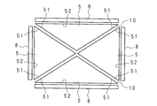
- FIG. 5 is a schematic front view of the illumination device 9 according to the third embodiment.
- the illumination device 9 includes two light guide plates 5 and 5 arranged in the diagonal direction of the display panel 2.
- the light guide plates 5 and 5 have a shape obtained by dividing a light guide plate having the same shape as the display panel 2 into two along one diagonal line, and each light guide plate 5 has a substantially right triangle.
- the oblique side of the light guide plate 5 is a facing end 51 that faces the other light guide plate 5.
- the corner of the light guide plate 5 facing the opposite end 51 is an incident end 53 where light is incident.
- the incident end portion 53 has an end surface that is substantially orthogonal to the light emitting surface.
- the light source 8 is disposed at a position close to the incident end portion 53 of each light guide plate 5 so as to face the end surface.
- the light source 8 is a point light source configured using LEDs. Light from the light source 8 is incident on the incident end portion 53, light is diffused in the light guide plate 5, and light is emitted from the light emitting surface toward the front surface.
- the display device includes an illumination device 9, and the configuration other than the light guide plates 5 and 5 and the light sources 8 and 8 is the same as that of the first embodiment.
- the positions of the incident end portions 53 of the light guide plates 5 and 5 are fixed.
- a gap 10 is provided between the light guide plates 5 and 5.
- the length of the gap 10 is equal to or greater than the total length of the opposing end portions 51 extending in a direction approaching each other when the light guide plates 5 and 5 expand according to changes in temperature or humidity.
- the position of the opposing end 51 of the light guide plate 5 is not fixed in the direction along the light emitting surface.
- the illuminating device 9 is not restricted to the form which made the angle
- the light source 8 has a configuration in which a plurality of LEDs are arranged in a straight line along the incident end that is the side of the light guide plate 5.
- the incident end portion 53 of the light guide plate 5 does not collide with the light source 8 even when the light guide plate 5 expands in accordance with a change in temperature or humidity. Further, since the expansion amount of the light guide plates 5 and 5 is absorbed by the gap 10, the light guide plates 5 and 5 do not warp, and the warped light guide plates 5 and 5 push the display panel 2 to cause unevenness of light on the display panel 2. Does not occur.
- the light source 8 is disposed as close as possible to the incident end 53 of the light guide plate 5, and the light use efficiency for displaying an image on the display device is high. improves.
- FIG. 6 is a schematic front view of the illumination device 9 according to the fourth embodiment.
- the illumination device 9 includes four light guide plates 5, 5,... Arranged in a matrix.
- the light guide plates 5, 5,... Have a shape in which a light guide plate having the same shape as the display panel 2 is divided in parallel with the long side at the center in the short side direction and further in parallel with the short side at the center in the long side direction. Yes.
- Each light guide plate 5 is rectangular. Two adjacent sides of the light guide plate 5 are opposed end portions 51 facing the other light guide plate 5.
- each light guide plate 5 a corner that is not adjacent to any of the opposing end portions 51, 51 that are adjacent two sides is an incident end portion 53 on which light is incident.
- the incident end portion 53 has an end surface that is substantially orthogonal to the light emitting surface.
- the light source 8 is disposed at a position close to the incident end portion 53 of each light guide plate 5 so as to face the end surface.
- the light source 8 is a point light source configured using LEDs. Light from the light source 8 is incident on the incident end portion 53, light is diffused in the light guide plate 5, and light is emitted from the light emitting surface toward the front surface.
- the display device includes an illumination device 9, and the configuration other than the light guide plates 5, 5,... And the light sources 8, 8,.
- the incident end 53 does not collide with the light source 8, and there is no possibility that the light source 8 is destroyed at high temperature or high humidity.
- the light guide plates 5, 5,... Expand in the direction in which the opposing end portions 51 approach each other, the amount of expansion is absorbed by the gap 10, and the light guide plates 5, 5,. Therefore, the warped light guide plates 5, 5,... Do not push the display panel 2 and light unevenness does not occur on the display panel 2.
- the light source 8 is disposed as close as possible to the incident end 53 of the light guide plate 5, and the light use efficiency for displaying an image on the display device is high. improves.
- FIG. 7 is a schematic front view of the illumination device 9 according to the fifth embodiment.
- the illuminating device 9 includes four light guide plates 5, 5,... With the light emitting surfaces aligned in the same direction.
- the light guide plates 5, 5,... Have a shape obtained by dividing a light guide plate having the same shape as the display panel 2 along two diagonal lines.
- Each light guide plate 5 is triangular.
- Two of the three sides of the light guide plate 5 are opposed end portions 51 that face the other light guide plate 5.
- a side different from the opposed end portions 51, 51 is an incident end portion 52 on which light is incident.
- the incident end portion 52 has an end surface substantially orthogonal to the light emitting surface.
- the light source 8 is disposed at a position close to the incident end portion 52 of each light guide plate 5 so as to face the end surface.
- the light source 8 has a configuration in which a plurality of LEDs are arranged in a straight line along the incident end portion 52. Light from the light source 8 is incident on the incident end portion 52, light is diffused in the light guide plate 5, and light is emitted from the light emitting surface toward the front surface.
- the display device includes an illumination device 9, and the configuration other than the light guide plates 5, 5,... And the light sources 8, 8,.
- a gap 10 is provided between two adjacent light guide plates 5 and 5.
- the length of the gap 10 is equal to or greater than the total length of the opposing end portions 51 extending in a direction approaching each other when the light guide plates 5, 5,... Expand according to changes in temperature or humidity. Further, the position of the opposing end 51 of the light guide plate 5 is not fixed in the direction along the light emitting surface.
- the incident end 52 does not collide with the light source 8. Further, since the expansion amount of the light guide plates 5, 5,... Is absorbed by the gap 10, the light guide plates 5, 5,. Light unevenness does not occur on the display panel 2.
- the light source 8 is arranged as close as possible to the incident end portion 52 of the light guide plate 5, and the use efficiency of light for displaying an image on the display device is improved. improves.
- FIG. 8 is a schematic cross-sectional view of the light guide plate 5 according to the sixth embodiment.
- the opposed end portion 51 of the light guide plate 5 has an end surface 54 that intersects the light emitting surface 50.
- the end faces 54 and 54 of the adjacent light guide plates 5 and 5 face each other.
- a reflective sheet (reflective material) 55 is attached to the end face 54.
- the reflection sheet 55 reflects the light that reaches the end surface 54 through the inside of the light guide plate 5 into the light guide plate 5.
- the light incident from the light source 8 and diffused in the light guide plate 5 is prevented from being emitted from the end face 54 by the reflection sheet 55, returned to the light guide plate 5, and finally emitted from the light emitting surface.
- the illuminating device 9 is not restricted to the form in which the reflective sheet 55 was stuck, and the form in which the reflective material was provided in the end surface 54 by application
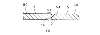
- FIG. 9 is a schematic cross-sectional view of the light guide plate 5 according to the seventh embodiment.
- the opposing end portion 51 of the light guide plate 5 has an end surface 54 that is inclined with respect to the light emitting surface 50.
- one end surface 54 is inclined at an acute angle with respect to the light emitting surface 50, the other end surface 54 is inclined at an obtuse angle with respect to the light emitting surface 50, and the end surfaces 54, 54 are They are facing each other.
- the end surfaces 54 and 54 of the adjacent light guide plates 5 and 5 are substantially parallel to each other, with a gap 10 therebetween and a part thereof overlapping in the thickness direction.
- the light guide plate 5 can emit light from the end face 54. For this reason, light can be emitted from between the light emitting surfaces 50 and 50 in a front view.
- the end face 54 is substantially orthogonal to the light emitting surface 50, there is a portion where the light guide plate 5 is not present and light is not emitted in the front view, but in the present embodiment, the light guide plate 5 is present in the front view.
- FIG. 10 is a schematic cross-sectional view of another example of the light guide plate 5 according to the seventh embodiment.
- the opposite end 51 of the light guide plate 5 has a tip formed by inclining an end surface 54 with respect to the light emitting surface 50.
- the corner of the tip of the opposed end 51 is chamfered.
- the strength of the opposed end 51 is improved. Therefore, the light guide plate 5 is prevented from being damaged, and the durability of the lighting device 9 and the display device is improved.
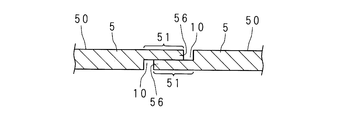
- the portion including the light emitting surface 50 is the protruding portion 56 on one of the opposed end portions 51 and 51, and the portion including the back surface of the light guide plate 5 is the protruding portion 56 on the other side.
- the protrusions 56 and 56 of the adjacent light guide plates 5 and 5 overlap in the thickness direction.
- the protrusions 56 and 56 that overlap in the thickness direction are in contact with each other. Further, a gap 10 is opened between the adjacent light guide plates 5 and 5 in the direction along the light emitting surface 50.
- the LED is used as the light source 8, but the illumination device 9 may be a light source other than the LED, such as a cold cathode tube.
- the lighting device 9 is used as the backlight of the display device.
- the lighting device 9 can be used for purposes other than the backlight, such as wall lighting. .
Landscapes
- Physics & Mathematics (AREA)
- General Physics & Mathematics (AREA)
- Optics & Photonics (AREA)
- Nonlinear Science (AREA)
- Engineering & Computer Science (AREA)
- General Engineering & Computer Science (AREA)
- Mathematical Physics (AREA)
- Chemical & Material Sciences (AREA)
- Crystallography & Structural Chemistry (AREA)
- Planar Illumination Modules (AREA)
Abstract
Description
(実施の形態1)
図1は、表示装置の正面図である。表示装置は、例えばテレビジョン受像機である。表示装置は、矩形板状の非発光型の表示パネル2及びバックライトを備えている。バックライトは本発明に係る照明装置からなる。表示パネル2は、バックライトにより後側から照明されて、画像を表示する。表示パネル2は例えば液晶パネルである。表示パネル2の周縁部はベゼル1に覆われている。ベゼル1は額縁状の金属製部材であり、表示装置の前面の周縁部分及び側面を覆っている。
図4は、実施の形態2に係る照明装置9の模式的正面図である。照明装置9は、表示パネル2の短辺方向に並んだ矩形の二つの導光板5,5を備える。導光板5,5は、表示パネル2と同形の導光板を短辺方向の中央で長辺に平行に分割した形状になっており、夫々の導光板5は矩形である。夫々の導光板5の端部は矩形の辺になっている。導光板5は、他の導光板5に対向した対向端部51を有し、導光板5において対向端部51に対向した端部は入射端部52になっている。対向端部51及び入射端部52は、表示パネル2の長辺方向にほぼ平行である。光源8は、各導光板5の入射端部52に近接した位置に端面に対向して配置されている。光源8は、矩形の辺である入射端部52に沿って複数のLEDが直線状に並んで構成されている。表示装置は、照明装置9を備えており、導光板5,5及び光源8,8以外の構成は実施の形態1と同様である。
図5は、実施の形態3に係る照明装置9の模式的正面図である。照明装置9は、表示パネル2の対角線方向に並んだ二つの導光板5,5を備える。導光板5,5は、表示パネル2と同形の導光板を一つの対角線に沿って二つに分割した形状になっており、夫々の導光板5は略直角三角形である。導光板5の斜辺は、他の導光板5に対向した対向端部51となっている。導光板5において対向端部51に対向した角は、光が入射される入射端部53になっている。入射端部53は、光放射面にほぼ直交した端面を有している。光源8は、各導光板5の入射端部53に近接した位置に、端面に対向して配置されている。光源8は、LEDを用いて構成された点光源である。光源8からの光が入射端部53へ入射され、導光板5内を光が拡散し、光放射面から前面方向へ光が放射される。表示装置は、照明装置9を備えており、導光板5,5及び光源8,8以外の構成は実施の形態1と同様である。
図6は、実施の形態4に係る照明装置9の模式的正面図である。照明装置9は、マトリクス状に並んだ四つの導光板5,5,…を備える。導光板5,5,…の光放射面は同一方向を向いている。導光板5,5,…は、表示パネル2と同形の導光板を短辺方向の中央で長辺に平行に分割し、更に長辺方向の中央で短辺に平行に分割した形状になっている。夫々の導光板5は矩形である。導光板5の隣接する二辺は、他の導光板5に対向した対向端部51となっている。各導光板5において、隣接する二辺である対向端部51,51の何れにも隣接していない角は、光が入射される入射端部53になっている。入射端部53は、光放射面にほぼ直交した端面を有している。光源8は、各導光板5の入射端部53に近接した位置に、端面に対向して配置されている。光源8は、LEDを用いて構成された点光源である。光源8からの光が入射端部53へ入射され、導光板5内を光が拡散し、光放射面から前面方向へ光が放射される。表示装置は、照明装置9を備えており、導光板5,5,…及び光源8,8,…以外の構成は実施の形態1と同様である。
図7は、実施の形態5に係る照明装置9の模式的正面図である。照明装置9は、光放射面を同一方向に向けて並んだ四つの導光板5,5,…を備える。導光板5,5,…は、表示パネル2と同形の導光板を二つの対角線に沿って分割した形状になっている。夫々の導光板5は三角形である。導光板5の三辺の内の二辺は、他の導光板5に対向した対向端部51となっている。導光板5において対向端部51,51とは別の辺は、光が入射される入射端部52になっている。入射端部52は、光放射面にほぼ直交した端面を有している。光源8は、各導光板5の入射端部52に近接した位置に、端面に対向して配置されている。光源8は、入射端部52に沿って複数のLEDが直線状に並んだ構成となっている。光源8からの光が入射端部52へ入射され、導光板5内を光が拡散し、光放射面から前面方向へ光が放射される。表示装置は、照明装置9を備えており、導光板5,5,…及び光源8,8,…以外の構成は実施の形態1と同様である。
実施の形態6に係る照明装置9の複数の導光板5及び光源8の構成は、実施の形態1~5の何れかと同様である。また、表示装置は、照明装置9を備えており、複数の導光板5及び光源8以外の構成は実施の形態1と同様である。図8は、実施の形態6に係る導光板5の模式的断面図である。導光板5の対向端部51は、光放射面50に交差した端面54を有している。隣り合う導光板5,5の端面54,54は互いに対向している。端面54には反射シート(反射材)55が貼着されている。反射シート55は、導光板5の内部を通って端面54に達した光を導光板5内へ反射する。光源8から入射されて導光板5内を拡散してきた光は、端面54から出射することを反射シート55に妨げられ、導光板5内へ戻され、最終的に光放射面から放射される。導光板5内へ入射した光の内、端面54から出射して表示パネル2の照明に寄与しない光の量が減少し、光の利用効率が向上する。なお、照明装置9は、反射シート55が貼着された形態に限るものではなく、塗布又は蒸着によって端面54に反射材が設けられた形態であってもよい。
実施の形態7に係る照明装置9の複数の導光板5及び光源8の構成は、実施の形態1~5の何れかと同様である。また、表示装置は、照明装置9を備えており、複数の導光板5及び光源8以外の構成は実施の形態1と同様である。図9は、実施の形態7に係る導光板5の模式的断面図である。導光板5の対向端部51は、光放射面50に対して傾斜した端面54を有している。隣り合う導光板5,5では、一方の端面54は光放射面50に対して鋭角に傾斜し、他方の端面54は光放射面50に対して鈍角に傾斜しており、端面54,54は互いに対向している。隣り合う導光板5,5の端面54,54は、互いにほぼ平行になっており、間に隙間10を開けて、厚さ方向に一部が重なっている。
実施の形態8に係る照明装置9の複数の導光板5及び光源8の構成は、実施の形態1~5の何れかと同様である。また、表示装置は、照明装置9を備えており、複数の導光板5及び光源8以外の構成は実施の形態1と同様である。図11は、実施の形態8に係る導光板5の模式的断面図である。隣り合う導光板5,5の対向端部51,51は、互いに厚さ方向に異なる位置で厚さ方向の一部が突出した突出部56,56を有している。図11に示した例では、対向端部51,51の一方では光放射面50を含んだ部分が突出部56となり、他方では導光板5の裏面を含んだ部分が突出部56となっている。隣り合う導光板5,5の突出部56,56は、厚さ方向に重なっている。厚さ方向に重なった突出部56,56は、互いに接触している。また、光放射面50に沿った方向には、隣り合う導光板5,5の間に隙間10が開けられている。
2 表示パネル
3 第1シャーシ
4 光学シート
5 導光板
50 光放射面
51 対向端部
52、53 入射端部
54 端面
55 反射シート(反射材)
56 突出部
6 反射シート
7 放熱板
8 光源
9 照明装置
10 隙間
Claims (6)
- 入射された光を放射する光放射面を有する導光板を備える照明装置において、
光放射面を同一方向に向けて隙間を開けて面状に並べた複数の導光板と、
各導光板の端部の内で他の導光板に対向していない部分の少なくとも一部分へ光を入射する光源とを備え、
前記複数の導光板は、各導光板の端部の内で前記光源から光が入射される部分の位置を固定してあること
を特徴とする照明装置。 - 前記隙間の大きさは、温度又は湿度の変化に応じて前記複数の導光板が前記光放射面に沿った方向に膨張する量以上の大きさであること
を特徴とする請求項1に記載の照明装置。 - 前記複数の導光板は、各導光板の端部の内で互いに対向した部分に、内部の光を反射する反射材を設けてあること
を特徴とする請求項1又は2に記載の照明装置。 - 前記複数の導光板の内で隣り合う二つの導光板は、端部の内で互いに対向した部分に、前記光放射面に対して一方が鋭角に傾斜し他方が鈍角に傾斜した端面を有しており、互いの該端面の一部が厚さ方向に重なっていること
を特徴とする請求項1又は2に記載の照明装置。 - 前記複数の導光板の内で隣り合う二つの導光板は、端部の内で互いに対向した部分に、互いに厚さ方向に異なる位置で突出した突出部を有しており、互いの該突出部の一部が厚さ方向に重なっていること
を特徴とする請求項1から3までの何れか一つに記載の照明装置。 - 画像を表示するための表示パネルと、
該表示パネルを一面から照明する請求項1から5までの何れか一つに記載の照明装置と
を備えることを特徴とする表示装置。
Priority Applications (2)
| Application Number | Priority Date | Filing Date | Title |
|---|---|---|---|
| CN201480043366.5A CN105431768B (zh) | 2013-08-02 | 2014-07-18 | 照明装置以及显示装置 |
| US14/908,282 US9829623B2 (en) | 2013-08-02 | 2014-07-18 | Lighting device and display apparatus |
Applications Claiming Priority (2)
| Application Number | Priority Date | Filing Date | Title |
|---|---|---|---|
| JP2013-161478 | 2013-08-02 | ||
| JP2013161478 | 2013-08-02 |
Publications (1)
| Publication Number | Publication Date |
|---|---|
| WO2015016091A1 true WO2015016091A1 (ja) | 2015-02-05 |
Family
ID=52431629
Family Applications (1)
| Application Number | Title | Priority Date | Filing Date |
|---|---|---|---|
| PCT/JP2014/069227 Ceased WO2015016091A1 (ja) | 2013-08-02 | 2014-07-18 | 照明装置及び表示装置 |
Country Status (3)
| Country | Link |
|---|---|
| US (1) | US9829623B2 (ja) |
| CN (1) | CN105431768B (ja) |
| WO (1) | WO2015016091A1 (ja) |
Cited By (2)
| Publication number | Priority date | Publication date | Assignee | Title |
|---|---|---|---|---|
| WO2016197394A1 (zh) * | 2015-06-09 | 2016-12-15 | 深圳市华星光电技术有限公司 | 背光模组以及液晶显示装置 |
| US10705279B2 (en) | 2018-09-05 | 2020-07-07 | Sharp Kabushiki Kaisha | Display device |
Families Citing this family (3)
| Publication number | Priority date | Publication date | Assignee | Title |
|---|---|---|---|---|
| US11086165B2 (en) | 2016-08-19 | 2021-08-10 | Samsung Display Co., Ltd. | Display apparatus and method of fabricating the same |
| CN111312080B (zh) * | 2020-03-31 | 2022-07-12 | 京东方科技集团股份有限公司 | 金属支撑件及柔性显示装置 |
| DE102020207235B4 (de) | 2020-06-10 | 2026-01-15 | Volkswagen Aktiengesellschaft | Scheibenverbund mit Lichtbarriere |
Citations (3)
| Publication number | Priority date | Publication date | Assignee | Title |
|---|---|---|---|---|
| JP2009283419A (ja) * | 2008-05-26 | 2009-12-03 | Citizen Electronics Co Ltd | 面状光源及び液晶表示装置 |
| JP2012164507A (ja) * | 2011-02-07 | 2012-08-30 | Panasonic Corp | バックライト装置および液晶表示装置 |
| JP2012199067A (ja) * | 2011-03-22 | 2012-10-18 | Konica Minolta Advanced Layers Inc | 照明装置 |
Family Cites Families (13)
| Publication number | Priority date | Publication date | Assignee | Title |
|---|---|---|---|---|
| US5438484A (en) | 1991-12-06 | 1995-08-01 | Canon Kabushiki Kaisha | Surface lighting device and a display having such a lighting device |
| JP3023026B2 (ja) | 1991-12-06 | 2000-03-21 | キヤノン株式会社 | 面照明装置 |
| CN2596387Y (zh) * | 2003-01-09 | 2003-12-31 | 山太士股份有限公司 | 导光板结构 |
| KR20070081564A (ko) * | 2006-02-13 | 2007-08-17 | 삼성전자주식회사 | 백라이트 어셈블리 및 이를 구비한 표시 장치 |
| DE102009022662A1 (de) | 2008-05-26 | 2010-01-14 | Citizen Electronics Co., Ltd., Fujiyoshida-shi | Planare licht-emittierende Anordnung und Flüssigkristall-Anzeigevorrichtung |
| TWI417587B (zh) * | 2009-03-10 | 2013-12-01 | Au Optronics Corp | 導光板組合 |
| KR101164094B1 (ko) * | 2009-07-14 | 2012-07-12 | 엘지이노텍 주식회사 | 백라이트 유닛 |
| JP2011040278A (ja) * | 2009-08-11 | 2011-02-24 | Sony Corp | 面状照明装置 |
| JP2011040279A (ja) * | 2009-08-11 | 2011-02-24 | Sony Corp | 面状照明装置 |
| CN101915396A (zh) * | 2010-07-28 | 2010-12-15 | 深圳市华星光电技术有限公司 | 一种导光板及液晶显示模组 |
| US8755007B2 (en) * | 2011-07-01 | 2014-06-17 | Seiko Epson Corporation | Liquid crystal device, electronic apparatus and lighting device |
| CN202600177U (zh) * | 2012-04-26 | 2012-12-12 | 京东方科技集团股份有限公司 | 导光板、侧入式背光模组及显示装置 |
| CN103912827A (zh) * | 2014-04-04 | 2014-07-09 | 京东方科技集团股份有限公司 | 背光源、液晶显示面板和液晶显示装置 |
-
2014
- 2014-07-18 WO PCT/JP2014/069227 patent/WO2015016091A1/ja not_active Ceased
- 2014-07-18 CN CN201480043366.5A patent/CN105431768B/zh not_active Expired - Fee Related
- 2014-07-18 US US14/908,282 patent/US9829623B2/en not_active Expired - Fee Related
Patent Citations (3)
| Publication number | Priority date | Publication date | Assignee | Title |
|---|---|---|---|---|
| JP2009283419A (ja) * | 2008-05-26 | 2009-12-03 | Citizen Electronics Co Ltd | 面状光源及び液晶表示装置 |
| JP2012164507A (ja) * | 2011-02-07 | 2012-08-30 | Panasonic Corp | バックライト装置および液晶表示装置 |
| JP2012199067A (ja) * | 2011-03-22 | 2012-10-18 | Konica Minolta Advanced Layers Inc | 照明装置 |
Cited By (3)
| Publication number | Priority date | Publication date | Assignee | Title |
|---|---|---|---|---|
| WO2016197394A1 (zh) * | 2015-06-09 | 2016-12-15 | 深圳市华星光电技术有限公司 | 背光模组以及液晶显示装置 |
| US10267978B2 (en) | 2015-06-09 | 2019-04-23 | Shenzhen China Star Optoelectronics Technology Co., Ltd. | Backlight module and liquid crystal display device |
| US10705279B2 (en) | 2018-09-05 | 2020-07-07 | Sharp Kabushiki Kaisha | Display device |
Also Published As
| Publication number | Publication date |
|---|---|
| CN105431768A (zh) | 2016-03-23 |
| US9829623B2 (en) | 2017-11-28 |
| US20160170132A1 (en) | 2016-06-16 |
| CN105431768B (zh) | 2019-08-20 |
Similar Documents
| Publication | Publication Date | Title |
|---|---|---|
| JP4902566B2 (ja) | 面状照明装置および表示装置 | |
| US8085359B2 (en) | Folded backlight systems having low index regions that prevent light failing to meet total internal reflection conditions from entering a plate portion and liquid crystal displays using the same | |
| JP5284489B2 (ja) | 面状照明装置およびそれを備えた表示装置 | |
| TWI451168B (zh) | 背光結構及其製造方法 | |
| TWI640819B (zh) | 背光模組 | |
| JP2008060204A (ja) | Ledバックライトユニットおよびそれを用いた液晶表示装置 | |
| CN102434821A (zh) | 背光结构及其制造方法 | |
| CN102865516B (zh) | 背光模组及led显示器 | |
| CN105431768B (zh) | 照明装置以及显示装置 | |
| WO2012133312A1 (ja) | バックライトユニット | |
| WO2014156618A1 (ja) | 光源モジュール及び表示装置 | |
| WO2015136625A1 (ja) | 光源装置、表示装置、及び光源装置の製造方法 | |
| US20120051090A1 (en) | Light guide plate and light source module | |
| WO2016086473A1 (zh) | 背光模组以及液晶显示器 | |
| CN101749666A (zh) | 背光模块的光源布设结构 | |
| CN102737557A (zh) | 显示装置 | |
| US9921357B2 (en) | Thin backlight with recycling to reduce the bezel width | |
| US20120127393A1 (en) | Display device | |
| WO2014038312A1 (ja) | 光源モジュール、照明モジュール及び照明機器 | |
| TW201333601A (zh) | 背光模組 | |
| JP4226511B2 (ja) | 照明装置および液晶表示装置 | |
| CN101169541A (zh) | 反射片及具有该反射片的背光模块 | |
| WO2013088594A1 (ja) | バックライト装置および液晶表示装置 | |
| WO2013024719A1 (ja) | 照明装置、表示装置、及びテレビ受信装置 | |
| JP5988136B2 (ja) | パネル部材、光学デバイス及び壁材 |
Legal Events
| Date | Code | Title | Description |
|---|---|---|---|
| WWE | Wipo information: entry into national phase |
Ref document number: 201480043366.5 Country of ref document: CN |
|
| 121 | Ep: the epo has been informed by wipo that ep was designated in this application |
Ref document number: 14831233 Country of ref document: EP Kind code of ref document: A1 |
|
| WWE | Wipo information: entry into national phase |
Ref document number: 14908282 Country of ref document: US |
|
| NENP | Non-entry into the national phase |
Ref country code: DE |
|
| 122 | Ep: pct application non-entry in european phase |
Ref document number: 14831233 Country of ref document: EP Kind code of ref document: A1 |
|
| NENP | Non-entry into the national phase |
Ref country code: JP |