WO2015012223A1 - 位相差板、楕円偏光板およびそれを用いた表示装置 - Google Patents
位相差板、楕円偏光板およびそれを用いた表示装置 Download PDFInfo
- Publication number
- WO2015012223A1 WO2015012223A1 PCT/JP2014/069210 JP2014069210W WO2015012223A1 WO 2015012223 A1 WO2015012223 A1 WO 2015012223A1 JP 2014069210 W JP2014069210 W JP 2014069210W WO 2015012223 A1 WO2015012223 A1 WO 2015012223A1
- Authority
- WO
- WIPO (PCT)
- Prior art keywords
- liquid crystal
- film
- wavelength
- retardation
- birefringence
- Prior art date
- Legal status (The legal status is an assumption and is not a legal conclusion. Google has not performed a legal analysis and makes no representation as to the accuracy of the status listed.)
- Ceased
Links
Images


Classifications
-
- G—PHYSICS
- G02—OPTICS
- G02B—OPTICAL ELEMENTS, SYSTEMS OR APPARATUS
- G02B5/00—Optical elements other than lenses
- G02B5/30—Polarising elements
- G02B5/3083—Birefringent or phase retarding elements
-
- H—ELECTRICITY
- H10—SEMICONDUCTOR DEVICES; ELECTRIC SOLID-STATE DEVICES NOT OTHERWISE PROVIDED FOR
- H10K—ORGANIC ELECTRIC SOLID-STATE DEVICES
- H10K59/00—Integrated devices, or assemblies of multiple devices, comprising at least one organic light-emitting element covered by group H10K50/00
- H10K59/80—Constructional details
- H10K59/8791—Arrangements for improving contrast, e.g. preventing reflection of ambient light
-
- G—PHYSICS
- G02—OPTICS
- G02F—OPTICAL DEVICES OR ARRANGEMENTS FOR THE CONTROL OF LIGHT BY MODIFICATION OF THE OPTICAL PROPERTIES OF THE MEDIA OF THE ELEMENTS INVOLVED THEREIN; NON-LINEAR OPTICS; FREQUENCY-CHANGING OF LIGHT; OPTICAL LOGIC ELEMENTS; OPTICAL ANALOGUE/DIGITAL CONVERTERS
- G02F1/00—Devices or arrangements for the control of the intensity, colour, phase, polarisation or direction of light arriving from an independent light source, e.g. switching, gating or modulating; Non-linear optics
- G02F1/01—Devices or arrangements for the control of the intensity, colour, phase, polarisation or direction of light arriving from an independent light source, e.g. switching, gating or modulating; Non-linear optics for the control of the intensity, phase, polarisation or colour
- G02F1/13—Devices or arrangements for the control of the intensity, colour, phase, polarisation or direction of light arriving from an independent light source, e.g. switching, gating or modulating; Non-linear optics for the control of the intensity, phase, polarisation or colour based on liquid crystals, e.g. single liquid crystal display cells
- G02F1/133—Constructional arrangements; Operation of liquid crystal cells; Circuit arrangements
- G02F1/1333—Constructional arrangements; Manufacturing methods
- G02F1/1335—Structural association of cells with optical devices, e.g. polarisers or reflectors
- G02F1/13363—Birefringent elements, e.g. for optical compensation
Definitions
- the present invention relates to a phase difference plate used for a liquid crystal display device, an organic electroluminescence display device and the like, and an image display device such as a liquid crystal display device and an organic electroluminescence display device using the same.
- the retardation film is an optical element used for obtaining polarized light (linearly polarized light, circularly polarized light, elliptically polarized light).
- Retardation plates are used for color compensation of liquid crystal display devices, viewing angle improvement film applications, antireflection film applications for organic EL display devices that combine polarizing plates and quarter-wave plates, and clockwise or counterclockwise rotation composed of cholesteric liquid crystals, etc. It is used in many applications such as a reflective polarizing plate that reflects only one of the circularly polarized light.
- phase difference plate a thin plate of inorganic material (calcite, mica, crystal), a stretched film made of a polymer material having a high intrinsic birefringence, a rod-like or disk-like liquid crystal material is aligned and fixed in the liquid crystal state. A film is used.
- a 1 ⁇ 4 wavelength plate having a retardation corresponding to 1 ⁇ 4 of a wavelength and a 1 ⁇ 2 wavelength plate having a retardation corresponding to 1 ⁇ 2 of a wavelength are known.
- the quarter-wave plate has an optical function of converting linearly polarized light into circularly polarized light.
- the half-wave plate has a function of converting the polarization vibration plane of linearly polarized light by 90 °.
- the retardation plate is usually designed to give a necessary optical function to light of a specific wavelength (monochromatic light).
- a quarter-wave plate used in a color compensation film for liquid crystal display devices and an antireflection film for organic EL display devices has a wavelength ( ⁇ ) in the visible light region of 400 to 700 nm, preferably in the wavelength region of 400 to 780 nm. It is necessary to have a function of converting linearly polarized light into circularly polarized light and circularly polarized light into linearly polarized light.
- the phase difference is that the phase difference becomes a quarter wavelength of the measurement wavelength, that is, ⁇ / 4 (nm) at a measurement wavelength of 400 to 700 nm, preferably 400 to 780 nm.
- the ideal of the board is that the phase difference becomes a quarter wavelength of the measurement wavelength, that is, ⁇ / 4 (nm) at a measurement wavelength of 400 to 700 nm, preferably 400 to 780 nm.
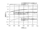
- FIG. 1 shows the chromatic dispersion characteristics of birefringence ( ⁇ n ( ⁇ )) at each wavelength in the visible light region normalized by setting the birefringence value ( ⁇ n (550 nm)) at a measurement wavelength of 550 nm to 1.
- the birefringence of a polymer film becomes larger as the measurement wavelength becomes shorter and becomes smaller as the longer wavelength. That is, it has “positive dispersion” characteristics.
- JP-A-10-68816 Patent Document 1
- JP-A-10-90521 Patent Document 2
- the retardation plate described in Patent Document 1 includes a quarter wavelength plate in which the phase difference of birefringent light is a quarter wavelength, and a half wavelength plate in which the phase difference of birefringent light is a half wavelength. Are bonded together with their optical axes intersecting.
- the retardation plate described in Patent Document 2 is a laminate in which at least two retardation plates having an optical retardation value of 160 to 320 nm are laminated so that their slow axes are not parallel or orthogonal to each other. It is.
- a multilayer retardation plate is disclosed in which the relationship of the phase difference R of each birefringent medium is R A > R B and the wavelength dispersion value ⁇ is smaller than 1.
- Each of the retardation plates disclosed in Patent Documents 1 to 3 described above is composed of a laminate of two birefringent media. By using such a laminated retardation plate, a wide wavelength region can be obtained. Can achieve a quarter-wave plate.
- a complicated process for adjusting the optical orientation (optical axis and slow axis) of the two polymer films is required.
- the optical orientation of the polymer film generally corresponds to the longitudinal or lateral direction of the sheet or roll film. Industrial production of a polymer film having an optical axis or a slow axis in an oblique direction of a sheet or roll is difficult.
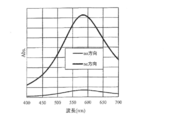
- the cause of the birefringence wavelength dispersion of the anisotropic rod-shaped molecule is that the two refractive indexes ne and no of the anisotropic molecule are toward the short wavelength side of the visible wavelength spectrum, as shown in FIG. This is because ne changes more rapidly than no.
- ne is an “abnormal refractive index” in a direction parallel to the long molecular axis, and no is an “ordinary refractive index” in a direction perpendicular to the long molecular axis.
- FIG. 3 shows the relationship of the refractive index of the rod-like molecule 1 in the polymer film 2.
- the functional group having a conjugated double bond is oriented in the major axis direction of the molecule, so the refractive index in the major axis direction (abnormal light refractive index ne) is in the visible light region. It has absorption in the near ultraviolet region and changes rapidly toward the short wavelength side of the visible wavelength spectrum, whereas the refractive index in the minor axis direction (ordinary ray refractive index) has a comparatively gentle curve. To do.
- One way to achieve higher dispersion of the “positive dispersion” property of birefringence is to design the numerator to increase the positive dispersion of ne and decrease the positive dispersion of no, as shown in FIG. is there.
- a method of designing a rod-like molecular structure having absorption in the ultraviolet region closer to the visible light region, or mixing a dye having absorption in the ultraviolet region with a polymer can be considered.
- Japanese Patent Application Laid-Open No. 2000-314885 discloses a retardation plate capable of arbitrarily controlling wavelength dispersion characteristics by mixing an additive that affects the wavelength dispersion characteristics of retardation with a polymer. Has been.
- the retardation plate described in Patent Document 4 has a short wavelength region compared to the original extraordinary refractive index of the material by adding a dye that absorbs in the ultraviolet region to orient the dye in the long axis direction of the rod-like molecule. It is designed to change more abruptly, and Patent Document 4 clearly states that the “positive dispersion” property of the phase difference can be further increased.
- a method for imparting a “negative dispersion” characteristic only a method of superimposing two polymer films added with a dye perpendicularly is disclosed.
- the molecule is designed to increase the positive dispersion of no and decrease the positive dispersion of ne as a tendency opposite to FIG. Although it is conceivable that no such material has been found at present.
- Patent Document 5 discloses a mixture of at least two kinds of organic polymers composed of an organic polymer having positive birefringence and an organic polymer having negative birefringence, or It is disclosed that a retardation film having “negative dispersion” characteristics can be realized with a single film by forming a retardation film obtained by uniaxially stretching a copolymer film.
- the retardation film described in Patent Document 5 will be described with reference to the schematic diagram shown in FIG. 5 and the birefringence wavelength dispersion graph shown in FIG.
- the wavelength dispersion characteristic D2 of the birefringence ⁇ n2 of the organic polymer having “negative birefringence”, D2 ⁇ n2 (450) / ⁇ n2 ( 650) (where ⁇ n2 (450) and ⁇ n2 (650) are the birefringence of the polymer film at the measurement wavelengths of 450 nm and 650 nm, respectively), as shown in FIG.
- the wavelength dispersion characteristic D2 of the organic polymer having “birefringence” is larger than the wavelength dispersion characteristic D1 of the organic polymer having “positive birefringence” (that is, D > D1) If designed to, as a mixture, a phase difference plate having a "positive birefringence” and "negative dispersion” characteristics.
- a retardation film formed by uniaxially stretching a copolymer film has a very small birefringence ⁇ n, and therefore it is necessary to increase the thickness to 50 to 200 ⁇ m in order to provide quarter-wave plate characteristics.
- a retardation layer used for a liquid crystal display device or an organic EL display device is required to be thinned, and a polymer stretched film having a small birefringence ⁇ n is desired to be improved from the viewpoint of film thickness.
- Patent Document 6 discloses a liquid crystal film made of a rod-like liquid crystal compound as a retardation plate that is a thin film and has a measurement wavelength that increases as the wavelength increases.
- the retardation plate described in Patent Document 6 aligns a liquid crystal compound containing a compound having two or more kinds of mesogenic groups and a rod-like liquid crystal molecule in parallel, and at least one kind of mesogen group is in the optical axis direction of the rod-like liquid crystal compound. , Making use of orientation in a substantially orthogonal direction.
- the rod-like liquid crystal compound has a relatively large birefringence ⁇ n compared to the copolymer resin, and therefore has a thickness of several ⁇ m, which is advantageous in terms of thinning the retardation plate.
- Japanese Patent Laid-Open No. 10-68816 Japanese Patent Laid-Open No. 10-90521 Japanese Patent Laid-Open No. 11-52131 JP 2000-314885 A JP 2002-48919 A JP 2002-267838 A
- the curve on the short wavelength side is kept close to the ideal straight line, while another method is used. An attempt to bring the wavelength curve closer to the ideal straight line is necessary.
- the inventors of the present invention now have an extraordinary ray refractive index ne and a long measurement wavelength in at least a part of the visible light region by mixing at least one dichroic dye with an organic polymer. It was found that a novel phase difference plate having a “negative dispersion” characteristic that becomes so large can be realized. In addition, by optimizing the birefringence wavelength dispersion characteristics of the polymerizable liquid crystal compound, the absorption maximum wavelength of the dichroic dye, and the mixing amount, and by optimizing the film forming conditions, the birefringence ⁇ n is reduced in the visible light region. In at least a part of the wavelength region, it has been found that a novel retardation plate having a “negative dispersion” characteristic that increases as the measurement wavelength increases can be obtained. The present invention is based on this finding.
- an object of the present invention is to provide a retardation plate composed of a single layer film in which an extraordinary ray refractive index ne or birefringence ⁇ n has a “negative dispersion” characteristic while minimizing a decrease in transmittance. It is.
- Another object of the present invention is to provide an elliptically polarizing plate having the retardation plate, a liquid crystal display device having the elliptically polarizing plate, and an image display device such as an organic electroluminescence display device.
- the retardation plate according to the present invention is a retardation plate comprising a film comprising an organic polymer and at least one dichroic dye,
- the retardation of the retardation plate is ⁇ na ⁇ da
- Retardation of a retardation plate made of a film obtained by removing the dichroic dye from the film is ⁇ nb ⁇ db
- the retardation plate satisfies the following expression (1).
- retardation is represented by the product of birefringence ⁇ n of the retardation plate and the film thickness d of the retardation plate, and ⁇ na ⁇ da (580) and ⁇ nb ⁇ db (580) are the retardations at a wavelength of 580 nm.
- the retardation of the plate, and ⁇ na ⁇ da (550) and ⁇ nb ⁇ db (550) are retardations of the respective retardation plates at a wavelength of 550 nm.
- the extraordinary ray refractive index ne or birefringence ⁇ n has a “negative dispersion” characteristic that increases as the measurement wavelength increases in at least a part of the wavelength region of the visible light region. Good.
- both the extraordinary ray refractive index ne and the birefringence ⁇ n have a “negative dispersion” characteristic that increases as the measurement wavelength increases in at least a part of the wavelength region of the visible light region. You may have.
- the retardation ratio of the retardation plate at a specific wavelength may satisfy the following expressions (2) and (3). 0.70 ⁇ n ⁇ d (450) / ⁇ n ⁇ d (550) ⁇ 1.00 (2) 1.00 ⁇ n ⁇ d (650) / ⁇ n ⁇ d (550) ⁇ 1.30 (3) (Here, ⁇ n ⁇ d (450), ⁇ n ⁇ d (550), and ⁇ n ⁇ d (650) are retardations of the retardation plate at wavelengths of 450 nm, 550 nm, and 650 nm, respectively).
- the retardation ratio of the retardation plate at a specific wavelength may satisfy the following formulas (4) and (5). 0.80 ⁇ n ⁇ d (500) / ⁇ n ⁇ d (550) ⁇ 1.10 (4) 1.00 ⁇ n ⁇ d (580) / ⁇ n ⁇ d (550) ⁇ 1.15 (5) (Here, ⁇ n ⁇ d (500), ⁇ n ⁇ d (550), and ⁇ n ⁇ d (580) are retardations of the retardation plate at wavelengths of 500 nm, 550 nm, and 580 nm, respectively).
- the birefringence of the organic polymer may have a “negative dispersion” characteristic.
- the organic polymer may be obtained by polymerizing a polymerizable liquid crystal compound in a predetermined liquid crystal alignment state, and the liquid crystal alignment may be parallel alignment.
- the organic polymer is a mixture or copolymer of at least two kinds of organic polymers composed of an organic polymer having positive birefringence and an organic polymer having negative birefringence. It may be.
- the film may be stretched.
- the absorption maximum wavelength of the dichroic dye may be in a range of a measurement wavelength of 380 to 780 nm.
- the absorption maximum wavelength of the dichroic dye may be different from the absorption maximum wavelength of the emission spectrum of the image display device.
- an elliptically polarizing plate including a retardation plate and a polarizing plate and an image display device including the elliptically polarizing plate are also provided.
- the image display device may be a liquid crystal display device or an organic electroluminescence display device.
- an extraordinary ray in at least a part of the wavelength region of the visible light region is obtained by mixing at least one dichroic dye with the organic polymer so as to satisfy the above formula (1).
- a novel phase difference plate having a “negative dispersion” characteristic in which the refractive index ne increases as the measurement wavelength increases can be realized.
- the birefringence wavelength dispersion characteristic of the polymerizable liquid crystal compound, the absorption maximum wavelength of the dichroic dye, the mixing amount are optimized, and the film formation conditions are optimized, thereby allowing the birefringence ⁇ n.
- the retardation plate having the birefringence wavelength dispersion as described above and having a phase difference of 1 ⁇ 4 wavelength at a measurement wavelength of 550 nm can convert circularly polarized light into linearly polarized light in a wide wavelength region. Because it functions as a phase difference plate that converts linearly polarized light into circularly polarized light, its brightness, contrast ratio, etc. are improved when used in liquid crystal display devices, and high anti-specular performance when used in organic electroluminescence display devices. Greatly improves the contrast.
- birefringence expresses a "negative dispersion" characteristic by the polymer film which consists of an organic polymer which has positive birefringence, and an organic polymer which has negative birefringence. It is a figure which shows the comparison with the phase difference plate which has a "negative dispersion
- FIG. 4 is a diagram showing wavelength dispersion characteristics of birefringence ⁇ n of the liquid crystal film produced in Example 1. It is a figure which shows the wavelength dispersion characteristic of the extraordinary ray refractive index ne of the liquid crystal film produced in Example 2, and the ordinary ray refractive index no. It is a figure which shows the wavelength dispersion characteristic of birefringence (DELTA) n of the liquid crystal film produced in Example 2.
- DELTA birefringence
- FIG. It is a figure which shows the wavelength dispersion characteristic of the extraordinary ray refractive index ne of the liquid crystal film produced in the comparative example 1, and the ordinary ray refractive index no. It is a figure which shows the wavelength dispersion characteristic of birefringence (DELTA) n of the liquid crystal film produced in the comparative example 1.
- FIG. It is a figure which shows the wavelength dispersion characteristic of the extraordinary ray refractive index ne of the liquid crystal film produced in the comparative example 2, and the ordinary ray refractive index no. It is a figure which shows the wavelength dispersion characteristic of birefringence (DELTA) n of the liquid crystal film produced in the comparative example 2.
- the retardation plate according to the present invention is a retardation plate made of a film comprising an organic polymer and at least one dichroic dye.
- the retardation of the retardation plate is ⁇ na ⁇ da
- Retardation of a retardation plate made of a film obtained by removing the dichroic dye from the film is ⁇ nb ⁇ db, In this case, the following formula (1) is satisfied.
- retardation is represented by the product of birefringence ⁇ n of the retardation plate and the film thickness d of the retardation plate, and ⁇ na ⁇ da (580) and ⁇ nb ⁇ db (580) are the retardations at a wavelength of 580 nm.
- the retardation of the plate, and ⁇ na ⁇ da (550) and ⁇ nb ⁇ db (550) are retardations of the respective retardation plates at a wavelength of 550 nm.
- K the imaginary part of N
- ⁇ the absorption coefficient
- the refractive index n in a region away from the intrinsic absorption wavelength monotonously decreases as the wavelength increases.
- the refractive index n in the wavelength region including intrinsic absorption regions b1, b2, and b3 in FIG. 8) increases rapidly as the wavelength increases.
- Such dispersion is called “anomalous dispersion”.
- “normal dispersion” is expressed as “positive dispersion” and “abnormal dispersion” is expressed as “negative dispersion”.
- the prior art proposed as a method for obtaining the “negative dispersion” characteristic in which the birefringence increases as the wavelength increases, and the organic polymer having the “positive birefringence” and the organic high-power having the “negative birefringence”.
- the copolymer or mixture of molecules has an extraordinary ray refractive index ne and an ordinary ray refractive index no both having a “positive dispersion” characteristic.
- the present invention by adding a dichroic dye having absorption in the visible light region to an organic polymer having a refractive index “positive dispersion” characteristic, at least a part of the wavelength in the visible light region is added.
- the design philosophy is fundamentally different from the prior art in that the extraordinary ray refractive index ne becomes a phase difference plate having “negative dispersion” characteristics than before the addition of the dichroic dye.
- the retardation plate according to the present invention is a retardation plate made of a film containing an organic polymer and at least one dichroic dye, and has retardation characteristics satisfying the above formula (1). It is a new phase difference plate.
- the retardation ratio at a predetermined wavelength of a retardation plate made of a film containing a dichroic dye is more than the retardation ratio at a predetermined wavelength of a retardation plate made of a film not containing a dichroic dye.
- the phase difference plate according to the present invention is a phase difference plate in which the extraordinary ray refractive index ne or the birefringence index ⁇ n has a “negative dispersion” characteristic in at least a part of the wavelength range of the visible light region.
- a design method of the extraordinary ray refractive index ne or the birefringence index ⁇ n having the “negative dispersion” characteristic that is the characteristic of the retardation plate according to the present invention will be described.
- a mixture or copolymer film of at least two kinds of organic polymers composed of an organic polymer having positive birefringence and an organic polymer having negative birefringence exemplified in Patent Document 5 above is uniaxially stretched.
- the phase difference plate has a “dispersion” characteristic.
- the long wavelength side deviates from the ideal straight line due to the difference in the slope of the curve on the shorter wavelength side and the longer wavelength side than the central wavelength of visible light 550 nm.
- the curve on the short wavelength side is maintained in a state close to the ideal straight line, and another method is used. An attempt to bring the wavelength curve closer to the ideal straight line is necessary.
- Fig. 9 shows an enlarged view of the "abnormal dispersion region" curve in Fig. 8.
- the contribution of anomalous dispersion is approximately zero at the maximum absorption value in the “abnormal dispersion region”
- the local maximum value of the refractive index is the absorption wavelength of the long wavelength side. It appears just before the half-wave peak value, and the local minimum value of the refractive index appears just after the half-wave peak value on the short wavelength side.
- ⁇ max, ⁇ +, and ⁇ are shown in FIG. 9 as ⁇ max, ⁇ +, and ⁇ . That is, there is a so-called “negative dispersion” characteristic in which the refractive index increases as the wavelength increases from ⁇ to ⁇ +.
- the design concept of the present invention will be described with reference to FIGS.
- the type of dipole differs depending on the axial direction.
- the rate no indicates a different “positive dispersion” curve.
- a dye having a high dichroism having an absorption spectrum having an absorption maximum wavelength at 580 nm as shown in FIG. 11 is added to this organic polymer, extraordinary ray refraction occurs in the wavelength region of 550 to 650 nm, which is near the absorption wavelength.
- a retardation plate having a characteristic that the ratio ne has “negative dispersion” is obtained.
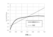
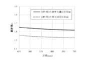
- FIG. 12 shows the birefringence wavelength dispersion characteristics of the retardation plate made of an organic polymer before and after the addition of the dichroic dye. It can be seen that by adding a dichroic dye, a retardation plate having birefringence having “negative dispersion” in a wavelength region of 550 to 650 nm can be obtained. From the above, by adding a dichroic dye having an anomalous dispersion region to a material (organic polymer) whose birefringence has “negative dispersion” characteristics, the entire wavelength of visible light, which is also an object of the present invention, is obtained. A retardation plate having a “negative dispersion” characteristic in which the birefringence is closer to the ideal in the region is obtained.
- FIG. 12 shows data obtained by adding a dichroic dye to an organic polymer whose birefringence has a “positive dispersion” characteristic.
- the retardation plate having the “negative dispersion” characteristic shown in FIG. 7 has a relatively close-to-ideal state on the shorter wavelength side than the visible light center wavelength of 550 nm, but on the longer wavelength side than 550 nm. Tend to deviate significantly from ideals.
- a high dichroic dye having an absorption maximum in the visible light region By adding and orienting a high dichroic dye having an absorption maximum in the visible light region to such a phase difference plate, the chromatic dispersion characteristic on the short wavelength side is maintained, and an ideal straight line is also formed on the long wavelength side. It is possible to have close dispersion characteristics.
- Patent Document 4 dyes that absorb in the ultraviolet region, dyes that absorb in the infrared region, and pigments that absorb in the visible region are listed as examples. Although there is an explanation about the design according to, there is no mention in Patent Document 4 regarding the design concept of the present invention of designing an extraordinary ray refractive index ne having a “negative dispersion” characteristic. In addition, the addition of a pigment material causes the retardation plate to be colored, which is a problem as a retardation plate material that is required to be transparent with visible light. However, Patent Document 4 avoids these problems. No method is mentioned.
- the retardation plate according to the present invention has a “negative dispersion” characteristic in which the extraordinary ray refractive index ne or birefringence ⁇ n becomes larger as the measurement wavelength is longer in at least a part of the wavelength region of the visible light region.
- the visible light region generally represents a wavelength region of 380 nm to 780 nm, but a region including the vicinity of the visible light center wavelength of 550 nm is preferable as the region where the refractive index ne exhibits “negative dispersion” characteristics. This is because the sensitivity of brightness perceived by human eyes for each wavelength (hereinafter referred to as specific visual sensitivity) is maximum near 555 nm, and maximum near 507 nm in dark places.
- the extraordinary ray refractive index ne is preferably larger as the wavelength is longer over the entire visible light wavelength, but as described later, it is necessary to increase the amount of the dye material added, which is not preferable in terms of coloring of the retardation plate.
- the "negative dispersion" characteristic can be obtained within the wavelength range of 550 to 650 nm, preferably within the wavelength range of 550 to 600 nm, the desired characteristic can be obtained sufficiently. It is.
- the retardation plate according to the present invention is characterized in that the birefringence ⁇ n has a “negative dispersion” characteristic that increases as the measurement wavelength increases in at least a part of the wavelength region of the visible light region. More specifically, retardations (product of birefringence ⁇ n and retardation film thickness d) at wavelengths of 450 nm, 550 nm, and 650 nm are respectively expressed as ⁇ n ⁇ d (450) and ⁇ n ⁇ d (550). , ⁇ n ⁇ d (650), it is preferable that the following expressions (2) and (3) are satisfied.
- retardation of the retardation plate (product of birefringence ⁇ n and retardation plate thickness d) at wavelengths of 500 nm, 550 nm, and 580 nm at a more preferable measurement wavelength of 550 nm to 580 nm,
- ⁇ n ⁇ d (500), ⁇ n ⁇ d (550), and ⁇ n ⁇ d (580) are satisfied, it is preferable that the following expressions (4) and (5) are satisfied.
- the retardation of the retardation plate is out of the above range, for example, when it is used as a quarter-wave plate, when a linearly polarized light of 400 to 700 nm is incident on this film, the polarization state obtained is a certain specific Although complete circularly polarized light can be obtained at wavelengths, it may deviate greatly from circularly polarized light at other wavelengths.
- the phase difference plate may be required to have not only a film thickness but also a specific phase difference value depending on its application.
- the retardation value ( ⁇ n ⁇ d) of the retardation plate is preferably 20 nm to 450 nm (more preferably 50 nm to 300 nm).
- “retardation value ( ⁇ n ⁇ d)” is a retardation value for light having a wavelength of 550 nm.
- the retardation value can be measured by a conventionally known method.
- a device capable of measuring birefringence for example, a trade name “Axoscan” manufactured by Axometrix, a trade name “KOBRA” manufactured by Oji Scientific Instruments). -21ADH "etc.).
- the retardation plate according to the present invention comprises a film containing an organic polymer and at least one dichroic dye.
- a film of a mixture of a polymer and a dichroic dye is formed on the film.
- the film may be stretched after being formed, or may be formed into a film by applying a mixture containing a liquid crystal compound and a dichroic dye to an alignment film and fixing the alignment of the liquid crystal compound in a predetermined liquid crystal alignment state.
- the dichroic dye and organic polymer used in the retardation plate according to the present invention will be described.
- the dichroic dye as used herein refers to a dye having a property that the absorbance in the major axis direction of the molecule is different from the absorbance in the minor axis direction.
- the dichroic dye is not particularly limited as long as it has such properties, and may be a dye or a pigment. A plurality of these dyes may be used, a plurality of pigments may be used, or a dye and a pigment may be combined. Furthermore, such a dichroic dye may have a polymerizable functional group and may have liquid crystallinity.
- an acrylic group, a methacryl group, a vinyl group, a vinyloxy group, an epoxy group, and an oxetanyl group are preferable, and an acrylic group, an epoxy group, and an oxetanyl group are particularly preferable from the viewpoint of reactivity.
- an acrylic group, an epoxy group, and an oxetanyl group are particularly preferable from the viewpoint of reactivity.
- the liquid crystallinity those having a nematic phase and a smectic phase are preferable.
- the dichroic dye preferably has a maximum absorption wavelength ( ⁇ max) in the range of 400 to 800 nm, more preferably 450 to 700 nm.
- ⁇ max maximum absorption wavelength
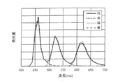
- FIG. 13 shows the emission spectrum of the organic electroluminescence display device when the three colors of red, blue, and green are simultaneously lit and white display is performed.
- blue has an emission spectrum having a maximum value at about 460 nm, green at 530 nm, and red at 630 nm.
- absorption by a dichroic dye is inevitable.
- the light emission of these three colors is used. It is preferable to select a dichroic dye having a maximum absorption at a wavelength outside the maximum wavelength of the spectrum.
- FIG. 11 shows the emission spectrum of the organic electroluminescence display device, but the same applies to other image display devices.
- the difference between the absorption maximum wavelength of the dichroic dye and the maximum wavelength of the emission spectrum of the image display device is 5 nm or more, preferably 10 nm or more, and more preferably 20 nm or more. If it is less than 5 nm, suppression of the transmittance
- the dichroic ratio of the dichroic dye is defined by the ratio of the absorbance at the maximum absorption wavelength in the major axis direction of the dye molecule to the absorbance in the minor axis direction.
- the dichroic ratio can be determined by measuring the absorbance in the orientation direction of the dye and the absorbance in the direction perpendicular to the orientation direction.
- the dichroic dye that can be used in the present invention has a dichroic ratio of preferably 2 or more and 50 or less, more preferably 5 or more and 30 or less.
- dichroic dyes there are no particular limitations on such dichroic dyes.
- Dye benzophenone dye, pyrazoline dye, diphenyl polyene dye, binaphthyl polyene dye, stilbene dye, benzothiazole dye, thienothiazole dye, benzimidazole dye, coumarin dye, nitrodiphenylamine dye, polymethine dye, naphthoquinone dye, perylene dye, quinophthalone dye, Examples thereof include stilbene dyes and indigo dyes.
- the dichroic dye is preferably an anthraquinone dye or an azo dye.
- azo dyes examples include monoazo dyes, bisazo dyes, trisazo dyes, tetrakisazo dyes, and stilbene azo dyes, and preferred examples include bisazo dyes, trisazo dyes, and derivatives of these series of dyes. Any dye that satisfies the above conditions can be used in the present invention.
- An example of a dye that can be used in the present invention is represented by the dye number described in the dye handbook (Edited by Shin Okawara, Shinjiro Kitao, Kosuke Hirashima, Kengo Matsuoka, Kodansha Scientific Co., Ltd., 1986, 1st edition). It is shown in 1.
- the dichroic dye is particularly preferably one represented by the following formula (1) (hereinafter sometimes referred to as “azo dye (1)”).
- n is an integer of 1 to 4, and Ar 1 and Ar 3 each independently represent a group selected from the following group.
- Ar 2 represents a group selected from the following group.
- n 2 or more, Ar 2 may be the same as or different from each other.
- a 1 and A 2 each independently represent a group selected from the following group.
- m is an integer of 0 to 10, and when there are two m's in the same group, these two m's may be the same or different.
- the positional isomerism of the azobenzene moiety of the azo dye (1) is preferably trans.
- Examples of the azo dye (1) include compounds represented by formulas (1-1) to (1-58).
- anthraquinone dye a compound represented by the formula (1-59) is preferable.
- R 1 to R 8 independently of one another represent a hydrogen atom, —Rx, —NH 2 , —NHRx, —NRx 2 , —SRx or a halogen atom.
- Rx has 1 to 4 carbon atoms. Represents an alkyl group or an aryl group having 6 to 12 carbon atoms.
- a compound represented by the formula (1-60) is preferable.
- R 9 to R 15 each independently represent a hydrogen atom, —Rx, —NH 2 , —NHRx, —NRx 2 , —SRx, or a halogen atom.
- Rx has 1 to 4 carbon atoms. Represents an alkyl group or an aryl group having 6 to 12 carbon atoms.
- a compound represented by the formula (1-61) is preferable.
- R 16 to R 23 each independently represent a hydrogen atom, —Rx, —NH 2 , —NHRx, —NRx 2 , —SRx, or a halogen atom.
- Rx has 1 to 4 carbon atoms. Represents an alkyl group or an aryl group having 6 to 12 carbon atoms.
- the alkyl group having 1 to 6 carbon atoms of Rx is a methyl group, an ethyl group, a propyl group, a butyl group, or pentyl.
- aryl groups having 6 to 12 carbon atoms include phenyl, toluyl, xylyl, and naphthyl groups.
- a compound represented by the formula (1-62) and a compound represented by the formula (1-63) are preferable.
- D 1 and D 2 each independently represent a group represented by any of the following formulas (1-62a) to (1-62d), and n5 represents an integer of 1 to 3) .
- D 3 and D 4 each independently represent a group represented by any of Formulas (1-63a) to (1-63h) below, and n6 represents 1 to Represents an integer of 3.
- the dichroic dye which the said phase difference plate contains it is preferable that it is an azo dye (1) as a dichroic dye, and an azo dye which has mutually different maximum absorption wavelength. You may contain at least 2 types (1).
- the content of the dichroic dye in the retardation plate can be adjusted as appropriate according to the type of the dichroic dye, and for example, 0.001 mass with respect to a total of 100 parts by mass of the organic polymer compound. Part or more and 50 parts by mass or less are preferable, 0.01 parts by mass or more and 10 parts by mass or less are more preferable, and 0.03 parts by mass or more and 1 part by mass or less are more preferable. If the content of the dichroic dye is within this range, the organic polymer can be formed or polymerized without disturbing the orientation of the organic polymer.
- content of the dichroic dye can be determined within a range in which the organic polymer can maintain the orientation.
- dye here means the total amount, when two or more types of dichroic pigment
- a polymer used as a stretched film from the viewpoint of maintaining the optical properties as an optical film, the optical isotropy is high and the light transmittance satisfies 80% or more, and from the viewpoint of cost and continuous productivity,
- polyester polymers such as polyvinyl alcohol, polyimide, polyphenylene oxide, polyphenylene sulfide, polysulfone, polyether ketone, polyether sulfone, polyether ether ketone, polyarylate, polyethylene terephthalate and polyethylene naphthalate; diacetyl cellulose and triacetyl cellulose Cellulose-based polymers; Polycarbonate-based polymers; Transparent polymers such as (meth) acrylic polymers such as polymethyl (meth) acrylate; Polystyrene, Acrylonitrile Styrene polymers such as len copolymers; Olefin polymers such as polyethylene, polypropy
- Cyclic olefin polymer is a general generic name for resins obtained from cyclic olefins such as norbornene, dicyclopentadiene, tetracyclododecene and derivatives thereof.
- organic polymer material as the material of such a base material, it is possible to exhibit characteristics (for example, transparency) suitable for an optical film, and therefore, a cellulose polymer, a polycarbonate polymer, a cyclic polymer, and the like.
- An olefin polymer (cycloolefin polymer: COP) is more preferable.
- a lower fatty acid ester of cellulose is more preferable.
- a lower fatty acid a fatty acid having 6 or less carbon atoms is preferable. Further, the number of carbon atoms of such a lower fatty acid is more preferably 2-4.
- examples of such a cellulose polymer include cellulose acetate, cellulose propionate, and cellulose butyrate. Among such cellulose polymers, cellulose triacetate is particularly preferable.
- a mixed fatty acid ester such as cellulose acetate propionate or cellulose acetate butyrate may be used.
- cyclic olefin polymer examples include cyclic olefin ring-opening polymers, cyclic olefin addition polymers, random copolymers of cyclic olefins and ⁇ -olefins such as ethylene and propylene, and the like. Examples include graft-modified products modified with saturated carboxylic acid and derivatives thereof, and hydrides thereof. Moreover, as such a cyclic olefin, norbornene, its derivative (s), and dicyclopentadiene are preferable.
- an organic polymer having positive birefringence and an organic polymer having negative birefringence as described in Patent Document 5 are used. It is preferable to use an organic polymer composed of a mixture or copolymer of at least two kinds of organic polymers composed of molecules.
- a mixing method of the organic polymer and the dichroic dye it is preferable to mix in a solution state in order to mix uniformly. Specifically, a method of suspending or dissolving the polymer in a solvent and suspending or dissolving the additive therein and mixing them can be mentioned.
- the solvent used in the present invention preferably has a higher solubility in a polymer.
- solvent casting methods in which dichroic dyes and organic polymers are dissolved in a solvent and cast, and extrusion molding that is kneaded in a solid state and extruded from a die.
- examples thereof include a calendering method, a calendering method in which a kneaded material is kneaded in a solid state, and a calendering method using a calender roll, and a press molding method in which a film is formed with a press.
- the solvent casting method excellent in film thickness accuracy is preferable.
- the thickness of the film after film formation is not particularly limited, but if it is too thin, the mechanical strength will be adversely affected, and if it is too thick, the evaporation rate of the solvent when the film is formed by the solvent casting method will be slowed, resulting in poor productivity. Therefore, the film thickness is preferably within a certain range.
- the thickness of the film after film formation is preferably 20 to 500 ⁇ m, more preferably 50 to 300 ⁇ m.
- Examples of the stretching method for stretching the film after heating after film formation include a tenter stretching method, an inter-roll stretching method, and an inter-roll compression stretching method. From the viewpoints of film surface uniformity, the tenter stretching method and the inter-roll stretching method are preferred.
- stretching methods it selects suitably by the softening temperature of the polymer to be used, and the transition temperature of a dichroic dye.
- the draw ratio if the ratio is low, the orientation is insufficient, and if it is too high, the film thickness becomes too thin and handling becomes difficult. Specifically, 1.1 times to 20 times is preferable, and 1.2 times to 15 times is more preferable.
- a liquid crystal film is a film obtained by aligning and fixing a liquid crystal compound in a liquid crystal state.
- the orientation of the liquid crystal film here refers to a state in which the molecular chains of the liquid crystal compound are arranged in a specific direction, and this state can be measured by measuring the phase difference ( ⁇ n ⁇ d) of the film.
- the orientation refers to, for example, ⁇ n ⁇ d of 20 nm or more at a measurement wavelength of 550 nm.
- ⁇ n ⁇ d is the product of the birefringence ⁇ n and the film thickness d of the liquid crystal film.
- the liquid crystal compound may be a low molecule or a polymer, and may be a polymer that is polymerized by polymerization or a crosslinking reaction.
- a method for fixing the alignment of the compound a polymerizable functional group is added to the liquid crystal compound to obtain a polymerizable liquid crystal compound, and the alignment state is fixed by polymerization, or the alignment state of the liquid crystal compound is changed to a glass transition temperature.
- a polymerizable liquid crystal compound is preferably used because the liquid crystal compound can be aligned at a relatively low temperature and the molecular design of the liquid crystal compound is easy.
- a polymerizable liquid crystal material constituting the liquid crystal film will be described.
- the polymerizable liquid crystal compound is not particularly limited as long as it is a liquid crystalline compound capable of fixing the alignment state by polymerization, and a known polymerizable liquid crystal compound can be appropriately used.
- a polymerizable liquid crystal compound it is preferable to use a polymerizable liquid crystal compound that can be aligned in parallel on the substrate and fix the alignment state.
- a polymerizable liquid crystal compound for example, a low molecular weight polymerizable liquid crystal compound (a liquid crystalline monomer having a polymerizable group), a high molecular weight polymerizable liquid crystal compound (a liquid crystalline polymer having a polymerizable group), And mixtures thereof can be used as appropriate.
- a liquid crystal compound having a polymerizable group that reacts with light and / or heat is preferable from the viewpoint that the alignment state can be more efficiently fixed.
- a liquid crystal compound having a polymerizable group that reacts with light or heat can be polymerized with components (liquid crystal compound, etc.) present around it by light and / or heat to fix the alignment.
- the kind is not specifically limited, A liquid crystal compound provided with a well-known polymeric group can be utilized suitably.
- Such a polymerizable group is preferably a vinyl group, a (meth) acryloyl group, a vinyloxy group, an oxiranyl group, an oxetanyl group, an aziridinyl group, or the like.
- other polymerizable groups such as an isocyanate group, a hydroxyl group, an amino group, an acid anhydride group, and a carboxyl group may be used depending on the reaction conditions.
- a liquid crystal compound having a (meth) acryloyl group as a polymerizable group is preferable from the viewpoint of availability, heat resistance, and handleability, and a (meth) acrylate liquid crystal compound ( It is more preferable to use (a liquid crystal compound having a (meth) acrylate group).
- “methacryloyl” and “acryloyl” are sometimes collectively referred to as “(meth) acryloyl”
- “methacrylate” and “acrylate” are sometimes collectively referred to as “( “Meth) acrylate”
- “methacryl” and “acryl” are collectively referred to as “(meth) acryl”.
- the “(meth) acrylate group” refers to a residue ((meth) acryloyloxy group) in which hydrogen is eliminated from the carboxyl group of (meth) acrylic acid.
- each W independently represents one of H and CH 3 .
- N is an integer of 1 to 20 (more preferably 2 to 12, more preferably 3 to 6). If the value of n is less than the lower limit, the temperature range in which the compound exhibits liquid crystallinity tends to be small. On the other hand, if it exceeds the upper limit, the liquid crystal derived from the compound is necessary to realize good parallel alignment. As a result of the decrease in fluidity, it tends to be difficult to achieve good parallel orientation.
- R a represents any group selected from an alkyl group having 1 to 20 carbon atoms and an alkoxy group having 1 to 20 carbon atoms.
- Such an alkyl group having 1 to 20 carbon atoms that can be selected as Ra is preferably one having 1 to 12 carbon atoms, and more preferably 3 to 6 carbon atoms.
- the number of carbon atoms exceeds the upper limit, the fluidity derived from the liquid crystal of the compound necessary for realizing good parallel alignment becomes small. As a result, realization of good parallel alignment tends to be difficult.
- the carbon number is less than the lower limit, the temperature range in which the compound exhibits liquid crystallinity tends to be small.
- Such an alkyl group may be linear, branched, or cyclic, and is not particularly limited. Is more preferably linear.
- the alkoxy group having 1 to 20 carbon atoms that can be selected as Ra is preferably one having 1 to 12 carbon atoms, and more preferably 3 to 6 carbon atoms.
- the number of carbon atoms exceeds the upper limit, the fluidity derived from the liquid crystal of the compound necessary for realizing good parallel alignment becomes small. As a result, realization of good parallel alignment tends to be difficult.
- the carbon number is less than the lower limit, the temperature range in which the compound exhibits liquid crystallinity tends to be small.
- the alkoxy group has a structure in which an alkyl group is bonded to an oxygen atom.
- the structure of the alkyl group portion may be linear, branched, or cyclic. Although not particularly limited, a straight-chain one is more preferable from the viewpoint of realizing a good parallel orientation.
- Z 1 and Z 2 each independently represent any group of —COO— and —OCO—.
- Such Z 1 and Z 2 are groups in which one of Z 1 and Z 2 is represented by —COO—, and the other group is — A group represented by OCO- is preferred.
- X 1 and X 2 each independently represent any of H and an alkyl group having 1 to 7 carbon atoms.
- the alkyl group having 1 to 7 carbon atoms which can be selected as X 1 and X 2 is more preferably 1 to 3 carbon atoms (the alkyl group is CH 3 ). Is more preferable.
- X 1 and X 2 are each independently one of H and CH 3 .
- examples of the (meth) acrylate liquid crystal compounds represented by the general formulas (10) to (12) include compounds described in the following general formulas (110) to (113). Such (meth) acrylate liquid crystal compounds may be used singly or in combination of two or more.
- the polymerizable liquid crystal compound it is preferable to use a combination of the compounds represented by the general formulas (10) to (12), and a combination of the compounds represented by the general formulas (110) to (113). It is more preferable to use it.
- the content of the compound represented by the general formula (10) is The amount is preferably 20 to 60% by mass, more preferably 30 to 45% by mass, based on the total amount of the compounds represented by formulas (10) to (12).
- the content of the compound represented by the general formula (10) is less than the lower limit, an orientation defect tends to occur with respect to the parallel orientation.
- the content exceeds the upper limit an orientation defect tends to occur with respect to the parallel orientation. It is in.
- the content of the compound represented by the general formula (11) is represented by the general formulas (10) to (12).
- the amount is preferably 10 to 50% by mass, more preferably 20 to 30% by mass, based on the total amount of the compounds represented.
- the content of the compound represented by the general formula (12) is represented by the general formulas (10) to (12).
- the amount is preferably 10 to 70% by mass, more preferably 25 to 45% by mass, based on the total amount of the compounds represented.
- the mass ratio of each compound is ([the above Compound Represented by General Formula (110)]: [Compound Represented by General Formula (111)]: [Compound Represented by General Formula (112)]: [Compound Represented by General Formula (113)]) Is preferably 45: 40: 15: 0 to 35: 5: 30: 30, and more preferably 35: 23: 23: 19 to 38: 25: 25: 12.
- the production method of the polymerizable liquid crystal compound is not particularly limited, and a known method can be appropriately used.
- a known method can be appropriately used.
- the compound represented by the above general formula (110) for example, the method described in British Patent Application Publication No. 2,280,445 may be adopted, and the above general formula ( 111) is produced, for example, D.I. J. et al.
- the method described in pages 3201 to 3215 of “Makromol. Chem. (Vol. 190, published in 1989)” by Broer et al. May be employed and is represented by the above general formulas (112) to (113).
- a method described in International Publication WO 93/22397 may be employed.
- the polymerizable liquid crystal compound can be produced by appropriately using a known method according to the type of the compound to be used. Moreover, you may utilize a commercial item as such a polymeric liquid crystal compound. Further, such polymerizable liquid crystal compounds may be used alone or in combination of two or more.
- the retardation ⁇ n ⁇ d (product of birefringence ⁇ n and the thickness d of the retardation plate) preferably satisfies the following expressions (1) and (2). 0.70 ⁇ n ⁇ d (450) / ⁇ n ⁇ d (550) ⁇ 1.00 (1) 1.00 ⁇ n ⁇ d (650) / ⁇ n ⁇ d (550) ⁇ 1.30 (2) Further, in consideration of the specific visibility characteristic, the retardation plate according to the present invention has a retardation ⁇ n ⁇ d (product of birefringence ⁇ n and the thickness d of the retardation plate) at a more preferable measurement wavelength of 550 nm to 580 nm.
- the polymerizable polymer compound is a compound having two or more kinds of mesogenic groups, and at least one of the mesogenic groups is arranged with respect to the slow axis of the parallel alignment of the liquid crystal layer.
- JP-A-2002-267838 and JP-A-2010-31223 describe that the phase difference increases as the wavelength increases by orienting in the substantially orthogonal direction.
- liquid crystal phase liquid crystal phase
- the mesogenic group in the rod-like liquid crystal is described in various documents (for example, Flussige Kristalle in Tabellen, VEB Deutscher Verlag fur Grundstoffindustrie, Leipzig (1984), Volume 2).
- mesogenic groups include biphenyl, phenylcyclohexyl, cyclohexylphenyl, phenyloxycarbonylphenyl, phenylcarbonyloxyphenyl, phenyloxycarbonylcyclohexyl, cyclohexylcarbonyloxyphenyl, phenylcarbonyloxyphenyloxycarbonylphenyl, phenylcarbonyloxyphenyloxycarbonylphenyl , Phenylcarbonyloxycyclohexyloxycarbonylphenyl, phenyloxycarbonylcyclohexylcarbonyloxyphenyl, phenylcarbonyloxyphenylaminocarbonylphenyl, phenylethenylenephenyl, phenylethynylenephenyl, phenylethynylenephenylethynylenephenyl, phenylethenylenecarbonyloxy Include biphenyl and pheny
- the mesogenic group (the benzene ring or the cyclohexane ring constituting the mesogenic group) may have a substituent.
- the substituent the polymerizable group described above or a derivative thereof is preferable.
- one mesogenic group is biphenyl, phenylcyclohexyl, cyclohexylphenyl, phenyloxycarbonylphenyl, phenylcarbonyloxyphenyl, phenyloxycarbonylcyclohexyl, cyclohexylcarbonyloxyphenyl, phenylcarbonyloxyphenyloxycarbonyl.
- phenyl Selected from the group consisting of phenyl, phenylcarbonyloxyphenyloxycarbonylphenyl, phenylcarbonyloxycyclohexyloxycarbonylphenyl, phenyloxycarbonylcyclohexylcarbonyloxyphenyl and phenylcarbonyloxyphenylaminocarbonylphenyl
- the other mesogenic group is phenylethenylenephenyl Phenylethynylenepheny , Phenyl ethynylene phenyl ethynylene phenyl, particularly preferably selected from the group consisting of phenyl et tennis alkylene carbonyloxy biphenyl and phenyl et tennis alkyleneoxy phenyl ethynylenes phenyl.
- a compound having two or more kinds of mesogenic groups can be synthesized by applying a general synthesis method. For example, 1) a sequential introduction method in which one of two or more kinds of mesogenic groups is first introduced by functional group conversion of the starting material, and then another mesogenic group is continuously introduced by functional group conversion; 2) starting material It is possible to adopt a simultaneous introduction method in which two or more kinds of mesogenic groups are simultaneously introduced by the functional group conversion of 3), or a combined method of 3) sequential introduction method and simultaneous introduction method.
- a method for producing a compound having two or more kinds of mesogenic groups is not particularly limited, and a known method can be appropriately used. For example, a method described in JP-A-2002-267838 May be adopted.
- the polymerizable liquid crystal compound can be produced by appropriately using a known method according to the type of the compound to be used.
- Other methods include: Japanese translations of PCT publication No. 2010-522892, Japanese translation No. 2010-522893, Japanese publication No. 2010-537954, Japanese publication No. 2010-535955, Japanese publication No. 2010-540472, Japanese translation table 2012- No. 532155, JP 2013-509458, JP 2007-2208, JP 2007-2209, JP 2007-2210, JP 2009-173893, JP 2010-30979.
- polymerizable liquid crystal compound a commercially available product may be used as the polymerizable liquid crystal compound.
- polymerizable liquid crystal compounds may be used alone or in a mixture of two or more.
- a mixture should just show liquid crystallinity.
- a compound having two or more kinds of mesogenic groups may have a liquid crystallinity with a mixture with another liquid crystal compound even if the compound itself does not exhibit liquid crystallinity.
- a mixture of two or more polymerizable liquid crystal compounds it is not necessary that all the liquid crystal compounds have a polymerizable functional group, and at least one liquid crystal compound has a polymerizable functional group. That's fine.
- Such a polymerizable liquid crystal compound may use a mixture of a liquid crystal compound having a polymerizable group and another polymerizable monomer that does not exhibit liquid crystallinity.
- Such other polymerizable monomers are not particularly limited as long as they have compatibility with a liquid crystal compound having a polymerizable group and do not cause significant alignment inhibition when the liquid crystal compound is aligned.
- a known polymerizable monomer can be appropriately used, and a suitable monomer may be selected from the known polymerizable monomers according to the design of the target liquid crystal composition.
- Examples of such other polymerizable monomers include compounds having a polymerizable functional group such as an ethylenically unsaturated group (for example, vinyl group, vinyloxy group, (meth) acryloyl group).
- the addition amount of such other polymerizable monomer is 0.5 to 50% by mass based on the total amount of the liquid crystal compound having a polymerizable group and the other polymerizable monomer not exhibiting liquid crystallinity.
- the content is preferably 1 to 30% by mass.
- the number of polymerizable functional groups of such a polymerizable monomer is preferably 2 or more from the viewpoint of sufficiently increasing the polymerization rate and imparting sufficient heat resistance to the obtained liquid crystal film.
- the method for producing such a polymerizable monomer is not particularly limited, and a known method can be appropriately used. Moreover, you may utilize a commercial item as such a polymerizable monomer.
- the polymerization initiator for polymerizing the polymerizable liquid crystal compound as described above is not particularly limited, and a known polymerization initiator can be appropriately used, and the polymerization in the composition can be performed from the known polymerization initiators. What is necessary is just to select suitably and use what can start superposition
- the polymerization initiator may be a thermal polymerization initiator (an initiator when using a thermal polymerization reaction) or a photopolymerization initiator (an initiator when using light or electron beam irradiation). Also good.
- a polymerization initiator in the case of using a plastic film or the like as a base material when producing a liquid crystal film, from the viewpoint of preventing the base material and the like from being deformed or altered by heat, It is more preferable to use a photopolymerization initiator.
- photopolymerization initiators include ⁇ -carbonyl compounds, acyloin ethers, ⁇ -hydrocarbon-substituted aromatic acyloin compounds, polynuclear quinone compounds, and triarylimidazole dimers and p-aminophenyl ketones. And acridine and phenazine compounds and oxadiazole compounds.
- ⁇ -carbonyl compounds include ⁇ -carbonyl compounds described in US Pat. No. 2,367,661 and US Pat. No. 2,367,670.
- examples of the acyloin ether include US Pat. The thing etc. which are described in 2448828 specification are mentioned.
- Examples of the ⁇ -hydrocarbon-substituted aromatic acyloin compound include those described in US Pat. No. 2,722,512.
- Examples of the polynuclear quinone compound include US Pat. No. 3,046,127 and US Pat. No. 2,951,758. And the like described in the specification.
- Examples of the combination of triarylimidazole dimer and p-aminophenyl ketone include those described in US Pat. No. 3,549,367.
- Examples of the acridine and phenazine compound include, for example, Examples described in JP-A-60-105667, US Pat. No. 4,239,850 and the like, and examples of the oxadiazole compound include those described in US Pat. No. 4,212,970. .
- photoinitiator you may utilize a commercial item, for example, the photoinitiator made from BASF (brand name “Irgacure 907", brand name “Irgacure 651", brand name “Irgacure 184").
- a photopolymerization initiator (trade name “UVI6974”) manufactured by Union Carbide may be used as appropriate.
- photopolymerization initiators include those that generate free radicals and those that generate ions upon irradiation with light or an electron beam, and the type and polymerization of the polymerizable liquid crystal compound in the composition.
- a photopolymerization initiator that generates free radicals for example, trade name “Irgacure 651” manufactured by BASF
- a photopolymerization initiator that generates ions for example, Union Carbide manufactured by A suitable photopolymerization initiator (trade name “UVI6974”)
- UVI6974 a photopolymerization initiator that generates free radicals
- UVI6974 a photopolymerization initiator that generates ions
- the content of the polymerization initiator is preferably 0.5 to 10 parts by mass, preferably 1 to 5 parts by mass with respect to 100 parts by mass of the mixture obtained by adding the dichroic dye to the polymerizable liquid crystal compound. It is more preferable.
- the content of the polymerization initiator is too small, the resulting retardation plate tends to have insufficient curability.
- the content of the polymerization initiator is too large, the orientation of the liquid crystal tends to be defective. .
- the method of producing the retardation plate is not limited to these, but a composition containing a polymerizable liquid crystal compound, a dichroic dye and various compounds added as necessary is in a molten state or the composition.
- a coating solution is formed by applying a solution of the product on an alignment substrate, and then the coating film is dried, heat-treated (alignment of liquid crystal), or if necessary, light irradiation and / or heat treatment (polymerization / crosslinking)
- the optically anisotropic layer in which the alignment of the liquid crystal and the dichroic dye is fixed is formed.
- the state that “the alignment state is fixed in the state of parallel alignment” is a state in which the parallel alignment (major axis direction of the liquid crystal molecules) is obtained in the optically anisotropic layer obtained by polymerizing the polymerizable liquid crystal compound and fixing the alignment.
- a component derived from a polymerizable liquid crystal compound or the like preferably a component derived from a polymerizable liquid crystal compound: its polymerization.
- Liquid crystal compound itself, a composition formed by decomposing the polymerizable liquid crystal compound, a polymer of the polymerizable liquid crystal compound, etc.) is fixed in a state of parallel alignment. That's fine.
- the solvent used for preparing the solution is not particularly limited as long as it can dissolve the polymerizable liquid crystal compound and the dichroic dye and can be distilled off under appropriate conditions.
- acetone, methyl ethyl ketone, isophorone, cyclohexanone, cyclopenta Ketones such as non, alcohols such as isopropyl alcohol and n-butanol, ether alcohols such as butoxyethyl alcohol, hexyloxyethyl alcohol, methoxy-2-propanol, ethylene glycol dimethyl ether, diethylene glycol dimethyl ether, 2-methoxyethyl acetate, Glycol ethers such as propylene glycol 1-monomethyl ether 2-acetate, esters such as ethyl acetate and ethyl lactate, phenols such as phenol and chlorophenol, N Amides such as N-dimethylformamide, N, N-dimethylacetamide, N-methylpyrrol
- a drying speed suitable for applying the solution so as to obtain a uniform film thickness, ease of handling (harmful to the environment), and dissolution in the polymerizable liquid crystal compound and the dichroic dye is preferred, and propylene glycol 1-monomethyl ether 2-acetate, toluene, and ⁇ -butyrolactone are more preferred.
- the content of the solvent used in the present invention the usage method of the composition (for example, when used for forming an optically anisotropic layer, the design of the thickness, the coating method, etc. are also included. However, it is preferably 30 to 98% by mass, more preferably 50 to 95% by mass, and 70 to 90% by mass. Is more preferable. If the content of such a solvent is too small, the amount of the solvent with respect to the mixture of the polymerizable liquid crystal compound and the dichroic dye decreases, so that the liquid crystal is deposited during storage, or the viscosity of the mixture increases and becomes wet. Since the (wetting) property is lowered, it tends to be difficult to perform coating during the production of the retardation plate.
- the amount of the mixture of components other than the solvent is preferably 2 to 70% by mass, and 5 to 50% by mass. More preferred is 10 to 30% by mass.
- the mixture of the polymerizable liquid crystal compound and the dichroic dye not only the above-mentioned solvent but also a reaction activator, a sensitizer, a surfactant, You may add an antifoamer, a leveling agent, etc.
- an alignment substrate for aligning the polymerizable liquid crystal compound As the alignment substrate, a substrate having a smooth plane is preferable, and examples thereof include a film or sheet made of an organic polymer material, a glass plate, and a metal plate. From the viewpoint of cost and continuous productivity, it is preferable to use a material made of an organic polymer.
- organic polymer materials include polyvinyl alcohol, polyimide, polyamide, polyamideimide, polyphenylene sulfide, polyether sulfone, polyphenylene oxide, polyether ketone, polyether ether ketone, polyethylene terephthalate, polyethylene naphthalate, polysulfone, polyarylate.
- polyester polymers such as cellulose polymers such as diacetylcellulose and triacetylcellulose, polycarbonate polymers, acrylic polymers such as polymethylmethacrylate, and transparent polymers such as epoxy resins and phenol resins.
- styrene polymers such as polystyrene, acrylonitrile / styrene copolymer, olefin polymers such as polyethylene, polypropylene, ethylene / propylene copolymer, cyclopolyolefins having cyclic or norbornene structure, vinyl chloride polymers, nylon and aromatic polyamides.
- a film made of a transparent polymer such as an amide polymer.
- imide polymers examples include a film made of a transparent polymer such as a polymer, an epoxy-based polymer, and a blend of the above polymers.
- a lower fatty acid ester of cellulose is more preferable.
- a lower fatty acid a fatty acid having 6 or less carbon atoms is preferable. Further, the number of carbon atoms of such a lower fatty acid is more preferably 2-4.
- examples of such a cellulose polymer include cellulose acetate, cellulose propionate, and cellulose butyrate. Among such cellulose polymers, cellulose triacetate is particularly preferable.
- a mixed fatty acid ester such as cellulose acetate propionate or cellulose acetate butyrate may be used.
- cyclic olefin polymer examples include cyclic olefin ring-opening polymers, cyclic olefin addition polymers, random copolymers of cyclic olefins and ⁇ -olefins such as ethylene and propylene, and the like. Examples include graft-modified products modified with saturated carboxylic acid and derivatives thereof, and hydrides thereof. Moreover, as such a cyclic olefin, norbornene, its derivative (s), and dicyclopentadiene are preferable. Commercially available products can also be used as the cyclic olefin polymer film. For example, ZEONOR (trade name, manufactured by ZEON CORPORATION), ZEONEX (trade name, manufactured by ZEON CORPORATION), Arton (trade name, JSR Corporation) )))))))))))))))))))))))))))))))))))))))))
- plastic films such as triacetyl cellulose, polycarbonate, norbornene polyolefin, and polyethylene terephthalate used as an optical film can be preferably used.
- plastic films such as triacetyl cellulose, polycarbonate, norbornene polyolefin, and polyethylene terephthalate used as an optical film can be preferably used.
- a metal film the said film formed from aluminum etc. is mentioned, for example.
- such a base material is not particularly limited, but depending on its use in the case of using a laminated body of an optically anisotropic layer and a base material as it is for an optical film or the like as it is. Thus, it may have a phase difference function.
- such a substrate may be uniaxially stretched (so-called uniaxially stretched film) or biaxially stretched (so-called biaxially stretched film).
- Such a base material may be used as a film having optical anisotropy by developing biaxial optical anisotropy by stretching the base material in the vertical direction and the horizontal direction.
- a substrate that has been subjected to a Z-axis orientation treatment may be used as such a base material. Further, such a substrate may be appropriately subjected to surface treatment such as corona treatment, plasma treatment, UV-ozone treatment, saponification treatment on one or both sides for the purpose of controlling the adhesion.
- the treatment conditions for adopting such a surface treatment may be appropriately set according to the base material to be used, and are not particularly limited, and known conditions may be appropriately adopted.
- the film may be stretched under appropriate heating, or the film surface may be rubbed in one direction with a rayon cloth or the like as required, or polyimide or polyvinyl alcohol may be applied on the film.
- An alignment film made of a known alignment agent such as a silane coupling agent is provided to perform rubbing treatment, or a photo-alignment film is applied on the film and heated at an appropriate temperature, and then irradiated with linearly polarized ultraviolet light to form an alignment film.
- You may use the film which expressed orientation ability by forming, performing oblique vapor deposition processing, such as a silicon oxide, or combining these means suitably.
- the peripheral speed ratio is usually 50 or less, more preferably 25 or less, and particularly preferably 10 or less.
- the peripheral speed ratio is larger than 50, the effect of rubbing is too strong, and the liquid crystal material cannot be completely aligned, and alignment may be insufficient, leading to characteristic deterioration.
- the application method is not particularly limited as long as the uniformity of the coating film is ensured, and a known method can be adopted. Examples thereof include spin coating, die coating, curtain coating, dip coating, and roll coating. Such a coating film differs depending on the content of the solvent in the mixture of the polymerizable liquid crystal compound and the dichroic dye, etc., and although it cannot be generally stated, the thickness of the coating film before drying (wet film) (Thickness) is preferably 3 to 50 ⁇ m, more preferably 5 to 20 ⁇ m.
- the thickness (wet film thickness) is too small, it is necessary to increase the concentration of the solid content (liquid crystal compound or the like) in the liquid crystal composition in order to obtain desired optical characteristics. Of the liquid crystal film is liable to occur and it becomes difficult to obtain a uniform liquid crystal film, and uniform coating is also difficult, and the smoothness of the liquid crystal film tends to decrease. On the other hand, when the thickness (wet film thickness) is too large, the concentration of the solid content in the liquid crystal composition for obtaining desired optical characteristics becomes thin, so that the drying time after coating tends to be long.
- the drying conditions differ depending on the polymerizable liquid crystal compound, the dichroic dye, the type of the solvent, and the like, and are not generally described, and are not particularly limited.
- the solvent can be removed from the coating film even at room temperature (25 ° C.).
- the temperature condition in such a solvent removal step is preferably 15 to 110 ° C., more preferably 20 to 80 ° C. In order to dry at a temperature below 15 ° C., a separate cooling facility may be required.
- the base material may be distorted by heat and optical characteristics and the like may be changed, and desired optical characteristics may not be obtained.
- the pressure condition in the drying step is not particularly limited, but is preferably 650 to 1400 hPa, more preferably 900 to 1100 hPa.
- the pressure condition is less than the lower limit, the solvent is rapidly dried and uneven drying tends to occur.
- the upper limit is exceeded, the solvent tends to take longer to dry.
- the time for the solvent removal step is not particularly limited, but is preferably 10 seconds to 60 minutes, and more preferably 30 seconds to 30 minutes. If the drying time is less than the lower limit, the solvent is rapidly dried, and the smoothness of the liquid crystal film tends to be reduced (drying unevenness occurs). Tend to decrease.
- the relative moving speed between the coating film and the drying apparatus is controlled so that the relative wind speed is 60 m / min to 1200 m / min.
- Any known method can be employed without particular limitation as long as the uniformity of the coating film is maintained.
- a method such as a heater (furnace) or hot air blowing may be used.
- the film thickness in the dry state of the applied film is preferably 0.1 ⁇ m to 50 ⁇ m, more preferably 0.2 ⁇ m to 20 ⁇ m. Outside this range, the optical performance of the obtained optically anisotropic layer may be insufficient, or the orientation of the polymerizable liquid crystal compound and the dichroic dye may be insufficient.
- a method for fixing the orientation will be described.
- a method for polymerizing the polymerizable liquid crystal compound to fix the alignment state a known polymerizable method can be appropriately employed depending on the type of the polymerization initiator used, the polymerizable liquid crystal compound, and the like.
- a method for fixing such an alignment state for example, depending on the type of the polymerization initiator or the like, a polymerizable group (reactive functional group) can be obtained by performing light irradiation and / or heat treatment. It is also possible to adopt a method in which the orientation is fixed in a parallel orientation state by reacting the group).
- the alignment state of parallel alignment is fixed by light irradiation.
- the light irradiation method is not particularly limited.
- a light source having a spectrum in the absorption wavelength region of the polymerization initiator used for example, a metal halide lamp, an intermediate pressure or a high pressure mercury lamp having an illuminance of 10 mW / cm 2 or more.
- a medium pressure or high pressure mercury ultraviolet lamp an ultra high pressure mercury lamp, a low pressure mercury lamp, a xenon lamp, an arc lamp, an LED, a laser, or the like
- the integrated irradiation dose of light in such a method of light irradiation of accumulative exposure at a wavelength 365 nm it is preferably 10 ⁇ 2000mJ / cm 2, and more to be 100 ⁇ 1500mJ / cm 2 preferable.
- this is not the case when the absorption region of the polymerization initiator and the spectrum of the light source are significantly different, or when the polymerizable liquid crystal compound itself has the ability to absorb light of the light source wavelength.
- an appropriate photosensitizer and two or more polymerization initiators having different absorption wavelengths are mixed.
- the temperature condition at the time of such light irradiation should just be made into the temperature range in which the said polymeric liquid crystal compound can maintain the alignment state of a parallel alignment, and is not restrict
- a cold mirror or other cooling device may be provided between the substrate and the light source (such as an ultraviolet lamp) so that the surface temperature of the coating film can maintain the range of the liquid crystal temperature during light irradiation.
- the atmospheric conditions at the time of light irradiation are not particularly limited, and may be an air atmosphere, or may be a nitrogen atmosphere in which oxygen is blocked in order to increase reaction efficiency. Since the oxygen concentration in the atmosphere is related to the degree of polymerization, when the desired degree of polymerization is not reached in the air, it is preferable to perform light irradiation in an atmosphere in which the oxygen concentration is reduced by a method such as nitrogen substitution. In such a case, the oxygen concentration in the atmospheric gas is preferably 10% by volume or less, more preferably 7% by volume or less, and most preferably 3% by volume or less.
- the polymerization initiator when it is such that the function of the initiator is expressed by heat (for example, in the case of a so-called thermal radical initiator or thermal cation generator), it is aligned in a parallel alignment state by heat treatment. Is preferably immobilized.
- the conditions for such heat treatment are not particularly limited, and the temperature conditions may be selected so that the orientation state is sufficiently maintained according to the type of the polymerization initiator, and known conditions are appropriately employed. be able to.
- the thing which expresses the function of an initiator by light irradiation is used as a polymerization initiator, and the alignment state of parallel alignment is fixed by light irradiation. It is preferable.
- the liquid crystal film manufactured by the above process is a sufficiently strong film.
- the mesogens are three-dimensionally bonded by the curing reaction, and not only the heat resistance (the upper limit temperature for maintaining the liquid crystal alignment) is improved as compared to before curing, but also scratch resistance, abrasion resistance, crack resistance.
- the mechanical strength such as property is also greatly improved.
- the solvent is removed from the coating to align the polymerizable liquid crystal compound and the dichroic dye, By fixing the liquid crystal state, a liquid crystal film in which the alignment state is fixed in a parallel alignment state can be formed on the alignment substrate.
- an optically isotropic substrate As the alignment substrate, it is not optically isotropic, or the obtained retardation plate is finally opaque in the intended use wavelength region, or the alignment substrate is too thick, which hinders actual use.
- an optically isotropic substrate a stretched film having a retardation function, or a form directly transferred to a polarizing plate can be used from the form formed on the alignment substrate.
- a transfer method a known method can be adopted. For example, as described in JP-A-4-57017 and JP-A-5-333313, a liquid crystal film is laminated on a substrate different from the alignment substrate via an adhesive or an adhesive, and then, if necessary, an adhesive is used. Examples include a method of transferring only the liquid crystal film by performing a surface curing treatment using an agent or an adhesive and peeling the alignment substrate from the liquid crystal film.
- the pressure-sensitive adhesive or adhesive used for transfer is not particularly limited as long as it is of optical grade, and generally used materials such as acrylic, epoxy, and urethane can be used.
- the liquid crystal film alone as the element, but in order to improve the strength and durability of the liquid crystal film, the retardation plate is covered with a transparent protective layer on one or both sides of the liquid crystal film.
- the transparent protective layer include those obtained by laminating transparent plastic films such as polyester and triacetyl cellulose directly or via an adhesive, resin coating layers, acrylic and epoxy photocurable resin layers, and the like. It is done. When these transparent protective layers are coated on both sides of the liquid crystal film, different protective layers may be provided on both sides.
- a liquid crystal film can be directly formed on a polarizing plate, and the elliptically polarizing plate of this invention can be used as it is.
- the polarizing film / transparent plastic film / retardation plate liquid crystal film
- a polarizing film / phase difference plate liquid crystal film
- the following method may be employed.
- a method for confirming the parallel alignment a known method can be appropriately employed, and is not particularly limited.
- a pair of orthogonal polarizing plates (the direction in which one deflector deflects and the direction in which the other deflector deflects)
- a method and a method for confirming transmitted light with the naked eye You may employ
- the liquid crystal film is a parallel-aligned liquid crystal film
- the phase difference of the light causes
- the amount of transmitted light when the incident angle of the light incident on the sample is tilted appears almost the same brightness in the direction opposite to the vertical direction. Therefore, the presence or absence of parallel orientation can be confirmed by measuring the brightness of such a sample through the naked eye or a polarizing microscope while shifting the incident angle of light.
- a method for confirming parallel alignment is, for example, perpendicular to the surface of the liquid crystal film.
- a birefringence measuring device (for example, manufactured by Axo-metrix) that can measure the phase difference in the direction (vertical incident angle) and the phase difference when the incident angle of light is tilted from the vertical incident angle to a specific angle.
- the angle is increased from 0 ° (perpendicular to the liquid crystal film) to a larger viewing angle.
- the phase difference is measured while appropriately changing, the phase difference of the sample is obtained at each of a plurality of viewing angles, and the phase difference is confirmed in a direction perpendicular to the surface of the liquid crystal film.
- the thickness of the liquid crystal film (the thickness of the cured film) is preferably 0.1 to 10 ⁇ m, more preferably 0.2 to 5 ⁇ m, although it varies depending on the application and required characteristics. If the thickness of the liquid crystal film is too small, the desired retardation may not be exhibited. On the other hand, if the thickness is too large, the orientation of the liquid crystal is decreased or the transmission due to the dye tends to be decreased.
- the elliptically polarizing plate provided with the above-mentioned phase difference plate and a polarizing plate is provided.
- the linear polarizing plate used in combination with the retardation plate one having a protective film on one side or both sides of the polarizer is usually used.
- the polarizer is not particularly limited, and various types can be used. For example, for a hydrophilic polymer film such as a polyvinyl alcohol film, a partially formalized polyvinyl alcohol film, an ethylene / vinyl acetate copolymer partially saponified film.
- polyene-based oriented films such as those obtained by adsorbing dichroic substances such as iodine and dichroic dyes and uniaxially stretched, polyvinyl alcohol dehydrated products and polyvinyl chloride dehydrochlorinated products.
- dichroic substances such as iodine and dichroic dyes
- uniaxially stretched, polyvinyl alcohol dehydrated products and polyvinyl chloride dehydrochlorinated products are preferably used.
- the thickness of the polarizer is not particularly limited, but is generally about 5 to 80 ⁇ m.
- a polarizer obtained by dyeing a polyvinyl alcohol film with iodine and uniaxially stretching it can be produced, for example, by dyeing polyvinyl alcohol in an aqueous iodine solution and stretching it 3 to 7 times the original length. If necessary, it can be immersed in an aqueous solution of boric acid or potassium iodide. Further, if necessary, the polyvinyl alcohol film may be immersed in water and washed before dyeing. In addition to washing the polyvinyl alcohol film surface with dirt and anti-blocking agents by washing the polyvinyl alcohol film with water, it also has the effect of preventing unevenness such as uneven coloring by swelling the polyvinyl alcohol film. is there.
- Stretching may be performed after dyeing with iodine, may be performed while dyeing, or may be dyed with iodine after stretching.
- the film can be stretched in an aqueous solution of boric acid or potassium iodide or in a water bath.
- the protective film provided on one side or both sides of the polarizer is preferably one that is excellent in transparency, mechanical strength, thermal stability, moisture shielding properties, isotropic properties, and the like.
- the material for the protective film include polyester polymers such as polyethylene terephthalate and polyethylene naphthalate, cellulose polymers such as diacetyl cellulose and triacetyl cellulose, acrylic polymers such as polymethyl methacrylate, polystyrene, acrylonitrile / styrene copolymers, and the like.
- polyester polymers such as polyethylene terephthalate and polyethylene naphthalate
- cellulose polymers such as diacetyl cellulose and triacetyl cellulose
- acrylic polymers such as polymethyl methacrylate, polystyrene, acrylonitrile / styrene copolymers, and the like.
- styrene polymers such as (AS resin), polycarbonate polymers, and the like.
- polyolefin polymers such as polyethylene, polypropylene, ethylene / propylene copolymers, polyolefins having cycloolefin or norbornene structures, vinyl chloride polymers, amide polymers such as nylon and aromatic polyamide, imide polymers, sulfones Polymer, polyether sulfone polymer, polyether ether ketone polymer, polyphenylene sulfide polymer, vinyl alcohol polymer, vinylidene chloride polymer, vinyl butyral polymer, arylate polymer, polyoxymethylene polymer, epoxy polymer, or Examples of the polymer that forms the protective film include blends of the aforementioned polymers.
- the thickness of the protective film is generally 500 ⁇ m or less, and preferably 1 to 300 ⁇ m. In particular, the thickness is preferably 5 to 200 ⁇ m.
- the protective film is preferably an optically isotropic substrate.
- a triacetyl cellulose (TAC) film such as Fujitac (product of Fujifilm) or Konicatak (product of Konica Minolta Opto), Arton film (product of JSR) And cycloolefin polymers such as ZEONOR film and ZEONEX film (product of Nippon Zeon), acrylic film, TPX film (product of Mitsui Chemicals), and acrylprene film (product of Mitsubishi Rayon)
- TAC triacetyl cellulose
- Fujitac product of Fujifilm
- Konicatak product of Konica Minolta Opto
- Arton film product of JSR
- cycloolefin polymers such as ZEONOR film and ZEONEX film (product of Nippon Zeon)
- acrylic film TPX film (product of Mitsui Chemicals)
- acrylprene film product of Mitsubishi Rayon
- the protective film which consists of the same polymer material may be used by the front and back, and the protective film which consists of a different polymer material etc. may be used.
- the polarizer and the protective film are usually in close contact with each other via a water-based pressure-sensitive adhesive or an ultraviolet curable adhesive.
- aqueous adhesives include polyvinyl alcohol adhesives, gelatin adhesives, vinyl latexes, aqueous polyurethanes, aqueous polyesters, and the like.
- substrate used for the phase difference plate which consists of a liquid crystal film may serve as the protective film of a polarizer.
- a hard coat layer As the protective film, a hard coat layer, an antireflection treatment, an anti-sticking treatment, or a treatment for diffusion or anti-glare can be used.
- Hard coat treatment is performed for the purpose of preventing scratches on the surface of the polarizing plate.
- a cured film having excellent hardness and slipping properties with an appropriate ultraviolet curable resin such as acrylic or silicone is applied to the protective film. It can be formed by a method of adding to the surface.
- the antireflection treatment is performed for the purpose of preventing reflection of external light on the surface of the polarizing plate, and can be achieved by forming an antireflection film or the like according to the conventional art. Further, the anti-sticking treatment is performed for the purpose of preventing adhesion with an adjacent layer.
- Anti-glare treatment is applied for the purpose of preventing external light from being reflected on the surface of the polarizing plate and obstructing the visibility of the light transmitted through the polarizing plate. For example, roughening by sandblasting or embossing. It can be formed by imparting a fine concavo-convex structure to the surface of the protective film by an appropriate method such as a method or a compounding method of transparent fine particles.
- the fine particles to be included in the formation of the fine surface uneven structure include conductive particles made of silica, alumina, titania, zirconia, tin oxide, indium oxide, cadmium oxide, antimony oxide, and the like having an average particle size of 0.5 to 50 ⁇ m.
- transparent fine particles such as inorganic fine particles, organic fine particles composed of a crosslinked or uncrosslinked polymer, and the like are used.
- the amount of fine particles used is generally about 2 to 50 parts by weight, preferably 5 to 25 parts by weight, based on 100 parts by weight of the transparent resin forming the surface fine uneven structure.
- the antiglare layer may also serve as a diffusion layer (viewing angle expanding function or the like) for diffusing the light transmitted through the polarizing plate to expand the viewing angle.
- the antireflection layer, antisticking layer, diffusion layer, antiglare layer and the like can be provided on the protective film itself, or can be provided separately from the transparent protective layer as an optical layer.
- the phase difference plate and the polarizing plate can be prepared by sticking each other through an adhesive layer, but if it is a phase difference plate made of a liquid crystal film, a mixture made of a polymerizable liquid crystal compound and a dichroic dye Can be directly applied to the polarizer of the polarizing plate through an alignment film or the like, and the alignment can be fixed.
- the pressure-sensitive adhesive forming the pressure-sensitive adhesive layer is not particularly limited.
- an acrylic polymer, a silicone-based polymer, a polyester, a polyurethane, a polyamide, a polyether, a fluorine-based or rubber-based polymer is appropriately used as a base polymer.
- those having excellent optical transparency such as an acrylic pressure-sensitive adhesive, exhibiting appropriate wettability, cohesiveness, and adhesive pressure-sensitive adhesive properties, and being excellent in weather resistance, heat resistance and the like can be preferably used.
- the formation of the pressure-sensitive adhesive layer can be performed by an appropriate method.
- a pressure-sensitive adhesive solution of about 10 to 40% by weight in which a base polymer or a composition thereof is dissolved or dispersed in a solvent composed of an appropriate solvent alone or a mixture such as toluene and ethyl acetate is prepared.
- a method in which it is directly attached on the liquid crystal layer by an appropriate development method such as a casting method or a coating method, or an adhesive layer is formed on the separator according to the above and transferred onto the liquid crystal layer Examples include methods.
- the pressure-sensitive adhesive layer includes, for example, natural and synthetic resins, in particular, tackifier resins, glass fibers, glass beads, metal powder, fillers made of other inorganic powders, pigments, colorants, You may contain the additive added to adhesion layers, such as antioxidant. Moreover, the adhesive layer etc. which contain microparticles
- the film surface when bonding each optically anisotropic layer mutually through an adhesive layer, the film surface can be surface-treated and adhesiveness with an adhesive layer can be improved.
- the surface treatment means is not particularly limited, and a surface treatment method such as corona discharge treatment, sputtering treatment, low-pressure UV irradiation, or plasma treatment that can maintain the transparency of each optically anisotropic layer can be suitably employed. Among these surface treatment methods, corona discharge treatment is good.
- An image display device includes an elliptical (circular) polarizing plate including the above-described retardation plate and a polarizing plate.
- the type of the image display device is not particularly limited, and a known image display device such as a liquid crystal display device, an organic EL display device, or a plasma display can be appropriately used.
- the method of arranging the elliptical (circular) polarizing plate in the image display device is not particularly limited, and a known method can be appropriately used.
- a liquid crystal display device to which the retardation plate according to the present invention is applied will be described.
- a liquid crystal display device is generally composed of a polarizing plate, a liquid crystal cell, and a retardation plate, a reflection layer, a light diffusion layer, a backlight, a front light, a light control film, a light guide plate, a prism sheet, and the like.
- the above-described retardation plate is used.
- the use position of the phase difference plate is not particularly limited, and may be one or a plurality of places. Moreover, it can also be used in combination with another phase difference plate.
- the liquid crystal cell is not particularly limited, and a general liquid crystal cell such as a liquid crystal layer sandwiched between a pair of transparent substrates provided with electrodes can be used.
- the transparent substrate constituting the liquid crystal cell is not particularly limited as long as the liquid crystal material constituting the liquid crystal layer is aligned in a specific alignment direction.
- a transparent substrate in which the substrate itself has a property of orienting liquid crystals a transparent substrate in which an alignment film having the property of orienting liquid crystals is provided, but the substrate itself lacks the alignment ability. Either can be used.
- a well-known thing can be used for the electrode of a liquid crystal cell. Usually, it can be provided on the surface of the transparent substrate in contact with the liquid crystal layer, and when a substrate having an alignment film is used, it can be provided between the substrate and the alignment film.
- the material exhibiting liquid crystallinity for forming the liquid crystal layer is not particularly limited, and examples thereof include various ordinary low-molecular liquid crystal substances, polymer liquid crystal substances, and mixtures thereof that can constitute various liquid crystal cells.
- a dye, a chiral agent, a non-liquid crystal substance, or the like can be added to these as long as liquid crystallinity is not impaired.
- the liquid crystal cell may include various components necessary to form various types of liquid crystal cells described later.
- Liquid crystal cell systems include TN (Twisted Nematic), STN (Super Twisted Nematic), ECB (Electrically Controlled Birefringence), IPS (In-Plane Switching), VA (Vertical Alignment), OCB (Optically Compensated). Birefringence method, HAN (Hybrid Aligned Nematic) method, ASM (Axially Symmetric Aligned Microcell) method, halftone gray scale method, domain division method, display method using ferroelectric liquid crystal and antiferroelectric liquid crystal, etc. The method is mentioned.
- the driving method of the liquid crystal cell there is no particular limitation on the driving method of the liquid crystal cell.
- the liquid crystal display device provided with the phase difference plate of the present invention has a desired birefringence wavelength dispersion characteristic because the phase difference plate has a desired birefringence wavelength dispersion characteristic. It is possible to improve the viewing angle and the image quality sufficiently.
- organic electroluminescence equipment An organic electroluminescence device (organic EL display device) to which the retardation plate according to the present invention is applied will be described.
- a transparent electrode, an organic light emitting layer, and a metal electrode are sequentially laminated on a transparent substrate to form a light emitter (organic electroluminescent light emitter).
- the organic light emitting layer is a laminate of various organic thin films, for example, a laminate of a hole injection layer made of a triphenylamine derivative and the like and a light emitting layer made of a fluorescent organic solid such as anthracene, Alternatively, a structure having various combinations such as a laminate of such a light emitting layer and an electron injection layer composed of a perylene derivative or the like, or a laminate of these hole injection layer, light emitting layer, and electron injection layer is known. It has been.
- holes and electrons are injected into the organic light-emitting layer by applying a voltage to the transparent electrode and the metal electrode, and the energy generated by recombination of these holes and electrons excites the phosphor material. Then, light is emitted on the principle that the excited fluorescent material emits light when returning to the ground state.
- the mechanism of recombination in the middle is the same as that of a general diode, and as can be predicted from this, the current and the emission intensity show strong nonlinearity with rectification with respect to the applied voltage.
- an organic EL display device in order to extract light emitted from the organic light emitting layer, at least one of the electrodes must be transparent, and a transparent electrode usually formed of a transparent conductor such as indium tin oxide (ITO) is used as an anode. It is used as.
- ITO indium tin oxide
- metal electrodes such as Mg—Ag and Al—Li are used.
- the organic light emitting layer is formed of a very thin film having a thickness of about 10 nm. For this reason, the organic light emitting layer transmits light almost completely like the transparent electrode. As a result, light that is incident from the surface of the transparent substrate at the time of non-light emission, passes through the transparent electrode and the organic light emitting layer, and is reflected by the metal electrode is again emitted to the surface side of the transparent substrate.
- the display surface of the organic EL display device looks like a mirror surface.
- an organic EL display device comprising an organic electroluminescent light emitting device comprising a transparent electrode on the surface side of an organic light emitting layer that emits light upon application of a voltage and a metal electrode on the back side of the organic light emitting layer, the surface of the transparent electrode While providing a polarizing plate on the side, a retardation plate can be provided between the transparent electrode and the polarizing plate.
- the retardation plate and the polarizing plate have a function of polarizing light incident from the outside and reflected by the metal electrode, there is an effect that the mirror surface of the metal electrode is not visually recognized by the polarization action.
- the mirror plate of the metal electrode can be completely shielded by forming the retardation plate with a quarter-wave plate and forming a circularly polarizing plate combining a linear polarizing plate and a retardation plate. That is, only the linearly polarized light component of the external light incident on the organic EL display device is transmitted by the polarizing plate.
- This linearly polarized light becomes generally elliptically polarized light by the retardation plate, but becomes circularly polarized light especially when the retardation plate is a quarter-wave plate and the angle between the polarization direction of the polarizing plate and the retardation plate is ⁇ / 4. .
- Circularly polarized light is transmitted through the transparent substrate, transparent electrode, and organic thin film, reflected by the metal electrode, again transmitted through the organic thin film, transparent electrode, and transparent substrate, and becomes linearly polarized light again on the retardation plate. And since this linearly polarized light is orthogonal to the polarization direction of a polarizing plate, it cannot permeate
- the angle between the absorption axis of the polarizing plate and the slow axis of the quarter-wave plate is defined as p in that a circular polarizing plate is formed by combining a quarter-wave plate with a linear polarizing plate
- the range is 40 ° to 50 °, preferably 42 to 48 °, more preferably about 45 °. In a range other than the above, there is a risk of image quality deterioration due to a decrease in the antireflection effect.
- each analysis method used in the Example is as follows.
- (1) Microscope observation The alignment state of the liquid crystal was observed with an Olympus BH2 polarizing microscope.
- (2) Refractive index Refractive indexes no and ne are measured using spectroscopic ellipsometry (product name “AUTO-SE” manufactured by HORIBA, Ltd.) under the conditions of a temperature of 20 ° C. ⁇ 2 ° C. and a relative humidity of 60 ⁇ 5%. A spectrum in the wavelength region of 440 to 1000 nm was measured.
- (3) Birefringence measurement An automatic birefringence meter Axoscan manufactured by Axometrics was used.
- (5) Measurement of polarization absorption spectrum and transmittance of dichroic dye Measurement was performed using a spectrum (V-570) manufactured by JASCO Corporation.
- Example 1 Preparation of mixed solution of polymerizable liquid crystal compound (A) and dichroic dye> First, polymerizable liquid crystal compounds (acrylate-based polymerizable liquid crystal compounds) represented by the following formulas (110) to (113) were prepared.
- Each polymerizable liquid crystal compound represented by the general formulas (110) to (113) was produced by a known method. Specifically, the compound represented by the above general formula (110) (hereinafter sometimes simply referred to as “liquid crystal compound (I)”) was described in British Patent Application Publication No. 2,280,445.
- the compound represented by the above general formula (111) (hereinafter, sometimes simply referred to as “liquid crystal compound (II)”) produced by the method is a document published in 1989 (DJ Broer et al., “ Makromol. Chem. ", Vol. 190, 1989, pp. 3201 to 3215), and a compound represented by the above general formula (112) (hereinafter sometimes referred to simply as” liquid crystal compound ").
- liquid crystal compound (IV) (hereinafter sometimes simply referred to as" liquid crystal compound (IV) ") are described in WO 93/22397. It was manufactured by the method. Further, all of the polymerizable liquid crystal compounds represented by the above general formulas (110) to (113) were solid at room temperature (25 ° C.).
- liquid crystal compounds (I) to (IV) are mixed with liquid crystal compound (I): 35 mass%, liquid crystal compound (II): 23 mass%, liquid crystal compound (III): 23 mass%, and liquid crystal compound ( IV): Mixing in a mass ratio of 19% by mass gave a first mixture (referred to as a polymerizable liquid crystal compound (A)).
- a dichroic dye (YM-2711 manufactured by Yamada Chemical Co., Ltd., merocyanine type, absorption maximum wavelength 550 nm) is added to the first mixture at a ratio of 0.3 parts by mass with respect to 100 parts by weight as a total.
- a polymerization initiator (trade name “Irgacure 907” manufactured by BASF, solid at room temperature (25 ° C.)) was added to the liquid crystal compounds (I) to (IV) and the dichroic dye in a total amount of 100 mass.
- the second mixture is dissolved in dichlorobenzene (solvent), the insoluble matter is filtered through a polytetrafluoroethylene filter having a pore size of 0.45 ⁇ m, and the liquid crystal compounds (I) to (IV), A mixed solution (third mixture) containing a dichroic dye, a polymerization initiator, and a solvent was obtained.
- the content of the solvent in the third mixture is 80% by mass, and the liquid crystal compounds (I) to (IV), the dichroic dye and the polymerization start The solvent was used so that the total amount with the agent was 20% by mass.
- the alignment substrate was prepared as follows. A 38 ⁇ m-thick polyethylene naphthalate film (manufactured by Teijin Limited) was cut into a 15 cm square, and a 5 wt% solution of alkyl-modified polyvinyl alcohol (PVA: MP-203, manufactured by Kuraray Co., Ltd.) (solvent was water and isopropyl (A mixed solvent of alcohol in a weight ratio of 1: 1) was applied by spin coating, dried on a hot plate at 50 ° C. for 30 minutes, and then heated in an oven at 120 ° C. for 10 minutes. Subsequently, it was rubbed with a rayon rubbing cloth.
- PVA alkyl-modified polyvinyl alcohol
- solvent A mixed solvent of alcohol in a weight ratio of 1: 1
- the film thickness of the obtained PVA layer was 1.2 ⁇ m.
- the peripheral speed ratio during rubbing (moving speed of rubbing cloth / moving speed of substrate film) was 4.
- a mixed solution (third mixture) containing the liquid crystal compounds (I) to (IV) obtained as described above, a dichroic dye, a polymerization initiator and a solvent is added on the alignment substrate thus obtained.
- Application (coating) was performed by a spin coating method to form a coating film (wet film thickness: 5 ⁇ m), and a laminate of the coating film and the alignment substrate was obtained.
- the laminate of the coating film and the alignment substrate was left to stand for 2 minutes under the conditions of pressure: 1013 hPa and temperature: room temperature (25 ° C.), thereby removing the solvent from the coating film by drying (solvent removal step).
- solvent removal step the solvent was removed from the entire surface of the coating film after 2 minutes had passed since the coating on the alignment substrate was completed.
- an ultraviolet light (however, 365 nm) is used by using a high-pressure mercury lamp with an illuminance of 15 mW / cm 2 so that the integrated irradiation amount becomes 200 mJ / cm 2.
- the liquid crystal compound is polymerized (cured) to fix the alignment state, and the liquid crystal film in which the alignment state is fixed is laminated on the alignment substrate. (Laminated body of liquid crystal film and alignment substrate) was obtained.
- the optically anisotropic layer on the obtained alignment substrate is subjected to triacetylcellulose (TAC) via an ultraviolet curable adhesive.
- TAC triacetylcellulose
- an adhesive is applied to a thickness of 5 ⁇ m, laminated with a TAC film, and irradiated with ultraviolet rays from the TAC film side to cure the adhesive. After that, the alignment substrate was peeled off.
- the extraordinary ray refractive index ne and ordinary ray refractive index no of the liquid crystal film layer of the obtained optical film were measured by spectroscopic ellipsometry.
- FIG. 14 shows the wavelength dispersion characteristics of the refractive index of the liquid crystal film layer, and Table 2 summarizes the optical characteristics results. In the measurement wavelength range of 540 to 570 nm, it was confirmed that the extraordinary ray refractive index increases as the measurement wavelength increases.
- the wavelength dispersion characteristic of retardation ( ⁇ nd) in the in-plane direction of the laminate of the TAC film and the liquid crystal film and the TAC film alone was measured using a trade name “Axoscan” manufactured by Axometrix, and the liquid crystal film layer was subtracted from both.
- the wavelength dispersion characteristics of the birefringence of was measured.
- FIG. 15 summarizes the birefringence wavelength dispersion characteristics of the liquid crystal film layer
- Table 2 summarizes the optical characteristics results.
- ⁇ n ⁇ d at 550 nm is 138 nm
- ⁇ n ⁇ d (500) / ⁇ n ⁇ d (550) 0.964
- ⁇ n ⁇ d (580) / ⁇ n ⁇ d (550) 1.010.
- ⁇ n ⁇ d (450) / ⁇ n ⁇ d (550) 1.030
- ⁇ n ⁇ d (650) / ⁇ n ⁇ d (550) 0.958.
- the phase difference increases as the measurement wavelength becomes longer.
- Example 2 Preparation of mixed solution of polymerizable liquid crystal compound (B) and dichroic dye> A compound (21) having two or more kinds of mesogenic groups represented by the following formula and a rod-like liquid crystal compound (22) were prepared. Compound (21) and rod-like liquid crystal compound (22) were produced by the method described in JP-A-2002-267838.
- a fourth mixture (referred to as a polymerizable liquid crystal compound (B)).
- the dichroic dye (M-137, manufactured by Mitsui Chemicals Fine Co., Ltd., anthraquinone type, absorption maximum wavelength 594 nm, 639 nm) becomes 2.0 parts by mass with respect to 100 parts by mass in total.
- a polymerization initiator (trade name “Irgacure 651” manufactured by BASF, solid at room temperature (25 ° C.)) is added, and the total amount of the polymerizable liquid crystal compound (B) and the dichroic dye is 100.
- the fifth mixture obtained as described above is dissolved in methyl ethyl ketone (solvent), and the insoluble matter is filtered through a polytetrafluoroethylene filter having a pore size of 0.45 ⁇ m, whereby the polymerizable liquid crystal compound (B)
- a mixed solution (sixth mixture) containing a dichroic dye, a polymerization initiator, and a solvent was obtained.
- the content of the solvent in the sixth mixture is 80% by mass, and the polymerizable liquid crystal compound (B), the dichroic dye, and the polymerization initiator are The solvent was used so that the total amount of was 20% by mass.
- FIG. 16 summarizes the wavelength dispersion characteristics of the refractive index of the liquid crystal film layer
- FIG. 17 summarizes the birefringence wavelength dispersion characteristics of the liquid crystal film layer
- Table 2 summarizes the optical characteristic results. In the measurement wavelength range of 570 to 620 nm, it was confirmed that the extraordinary ray refractive index increases as the measurement wavelength increases.
- ⁇ n ⁇ d 500
- / ⁇ n ⁇ d (550) 1.018
- ⁇ n ⁇ d (580) / ⁇ n ⁇ d (550) 1.030
- ⁇ n ⁇ d at 550 nm is 138 nm
- ⁇ n ⁇ d (450) / ⁇ n ⁇ d (550) 0.962
- ⁇ n ⁇ d (650) / ⁇ n ⁇ d (550) 1.273. It was. In particular, in the measurement wavelength range of 400 nm to 510 nm and 560 to 660 nm, it was confirmed that the phase difference increases as the measurement wavelength increases.
- Example 3 Preparation of mixed solution of polymerizable liquid crystal compound (C) and dichroic dye> Mixing at a mass ratio of 23% by mass of the first mixture (polymerizable liquid crystal compound (A)) produced in Example 1 and 77% by mass of the fourth mixture (polymerizable liquid crystal compound (B)) produced in Example 2. As a result, a seventh mixture (referred to as a polymerizable liquid crystal compound (C)) was obtained. Next, to the seventh mixture, the same dichroic dye as in Example 1 was added at a ratio of 0.3 parts by mass with respect to 100 parts by weight in total, and further a polymerization initiator (manufactured by BASF Corporation).
- a polymerization initiator manufactured by BASF Corporation
- a mixed solution (ninth mixture) containing a polymerization initiator and a solvent was obtained.
- the content of the solvent in the ninth mixture is 80% by mass, and the polymerizable liquid crystal compound (C), the dichroic dye, the polymerization initiator, The solvent was used so that the total amount of was 20% by mass.
- FIG. 18 summarizes the wavelength dispersion characteristics of the refractive index of the liquid crystal film layer
- FIG. 19 summarizes the birefringence wavelength dispersion characteristics of the liquid crystal film layer
- Table 2 summarizes the optical characteristic results.
- the measurement wavelength range of 540 to 560 nm it was confirmed that the extraordinary ray refractive index increases as the measurement wavelength increases.
- ⁇ n ⁇ d at 550 nm is 138 nm
- ⁇ n ⁇ d (500) / ⁇ n ⁇ d (550) 0.926
- ⁇ n ⁇ d (580) / ⁇ n ⁇ d (550) 1.024.
- ⁇ n ⁇ d (450) / ⁇ n ⁇ d (550) 0.961
- ⁇ n ⁇ d (650) / ⁇ n ⁇ d (550) 0.971.
- the phase difference increases as the measurement wavelength becomes longer.
- Example 4 A total amount of 100 parts by weight of the dichroic dye (manufactured by Nagase Sangyo, G-241, trisazo dye, absorption maximum wavelength 560 nm) with respect to the fourth mixture (polymerizable liquid crystal compound (B)) produced in Example 2
- a mixed solution and an optical film were obtained in the same manner as in Example 2 except that 0.2% by mass was added.
- FIG. 20 summarizes the birefringence wavelength dispersion characteristics of the liquid crystal film layer, and Table 2 summarizes the optical characteristics results.
- ⁇ n ⁇ d at 550 nm is 138 nm
- ⁇ n ⁇ d (500) / ⁇ n ⁇ d (550) 0.963
- ⁇ n ⁇ d (580) / ⁇ n ⁇ d (550) 1.016. Met.
- ⁇ n ⁇ d (450) / ⁇ n ⁇ d (550) 0.897
- ⁇ n ⁇ d (650) / ⁇ n ⁇ d (550) 1.038.
- the phase difference increases as the measurement wavelength increases.
- Example 5 A total amount of 100 parts by weight of the dichroic dye (manufactured by Nagase Sangyo, G-241, trisazo dye, absorption maximum wavelength 560 nm) with respect to the fourth mixture (polymerizable liquid crystal compound (B)) produced in Example 2
- a mixed solution and an optical film were obtained in the same manner as in Example 2 except that 0.08 parts by mass was added.
- FIG. 21 summarizes the birefringence wavelength dispersion characteristics of the liquid crystal film layer, and Table 2 summarizes the optical characteristics results.
- ⁇ n ⁇ d at 550 nm is 138 nm
- ⁇ n ⁇ d (500) / ⁇ n ⁇ d (550) 0.993
- ⁇ n ⁇ d (580) / ⁇ n ⁇ d (550) 1.014.
- ⁇ n ⁇ d (450) / ⁇ n ⁇ d (550) 0.910
- ⁇ n ⁇ d (650) / ⁇ n ⁇ d (550) 1.029.
- the phase difference increases as the measurement wavelength increases.
- Example 6 Dichroic dye (manufactured by Showa Processing, KDR-902, diazo dye, absorption maximum wavelength 570 nm) to the fourth mixture (polymerizable liquid crystal compound (B)) produced in Example 2 in a total amount of 100 parts by weight
- a mixed solution and an optical film were obtained in the same manner as in Example 2 except that 0.2% by mass was added.
- FIG. 22 summarizes the birefringence wavelength dispersion characteristics of the liquid crystal film layer, and Table 2 summarizes the optical characteristics results.
- ⁇ n ⁇ d at 550 nm is 138 nm
- ⁇ n ⁇ d (500) / ⁇ n ⁇ d (550) 0.966
- ⁇ n ⁇ d (580) / ⁇ n ⁇ d (550) 1.024.
- ⁇ n ⁇ d (450) / ⁇ n ⁇ d (550) 0.894
- ⁇ n ⁇ d (650) / ⁇ n ⁇ d (550) 1.042.
- FIG. 23 summarizes the wavelength dispersion characteristics of the refractive index of the liquid crystal film layer
- FIG. 24 summarizes the wavelength dispersion characteristics of the birefringence of the liquid crystal film layer
- Table 2 summarizes the optical characteristic results.
- the measurement wavelength range of 450 to 700 nm it was confirmed that the extraordinary ray refractive index decreases as the measurement wavelength increases.
- ⁇ n ⁇ d at 550 nm is 138 nm
- ⁇ n ⁇ d (500) / ⁇ n ⁇ d (550) 1.033
- ⁇ n ⁇ d (580) / ⁇ n ⁇ d (550) 0.985.
- ⁇ n ⁇ d (450) / ⁇ n ⁇ d (550) 1.080
- ⁇ n ⁇ d (650) / ⁇ n ⁇ d (550) 0.957.
- the phase difference was smaller as the measurement wavelength was longer.
- FIG. 25 shows the wavelength dispersion characteristics of the refractive index of the liquid crystal film layer
- FIG. 26 shows the birefringence wavelength dispersion characteristics of the liquid crystal film layer
- the longer the measurement wavelength the larger the phase difference.
- 550 nm or more it was confirmed that the retardation value was almost constant regardless of the measurement wavelength.
- the extraordinary ray refractive index decreases as the measurement wavelength becomes longer in the measurement wavelength range of 450 to 700 nm.
- the phase difference was smaller as the measurement wavelength was longer.
- FIG. 27 summarizes the wavelength dispersion characteristics of the refractive index of the liquid crystal film layer
- FIG. 28 summarizes the birefringence wavelength dispersion characteristics of the liquid crystal film layer
- Table 2 summarizes the optical characteristic results.
- the measurement wavelength range of 450 to 700 nm it was confirmed that the extraordinary ray refractive index decreases as the measurement wavelength increases.
- ⁇ n ⁇ d at 550 nm is 138 nm
- ⁇ n ⁇ d (500) / ⁇ n ⁇ d (550) 1.013
- ⁇ n ⁇ d (580) / ⁇ n ⁇ d (550) 0.990. Met.
- ⁇ n ⁇ d (450) / ⁇ n ⁇ d (550) 1.016
- ⁇ n ⁇ d (650) / ⁇ n ⁇ d (550) 0.993.
- the phase difference was smaller as the measurement wavelength was longer.
- Example 1 and Comparative Example 3 Examples 2, 4 to 6 and Comparative Example 2 are compared in Example 3 and Comparative Example 3.
- the transmittance of the film not mixed with the dichroic dye (Comparative Examples 1 to 3) is 1
- the transmittance of the film mixed with the dichroic dye (Examples 1 to 3) is approximately 0.9 to It was 0.96, and it was found that the decrease in transmittance can be suppressed within 10%.
- Example 7 The liquid crystal film produced in Example 2 was incorporated into a polarizing plate reflective liquid crystal display device and evaluated. From the observation side, the configuration is polarizing plate / liquid crystal film prepared in Example 2 / glass substrate / ITO transparent electrode / alignment film / twist nematic liquid crystal / alignment film / metal electrode / reflection film / glass substrate. The adhesive layer between each layer is omitted. The color was evaluated visually by setting the bonding angle so as to display white when the voltage was turned off. In particular, it was confirmed that there was little coloration in black display when the voltage was turned on, thereby providing high contrast and excellent visibility.
- Example 8 The optical film produced in Example 2 was bonded via a commercially available polarizing plate (Sumitomo Chemical Co., Ltd. SRW062) with an acrylic adhesive so that the absorption axis of the polarizing plate and the optical axis of the optical film were 45 degrees. Then, a circularly polarizing plate was prepared, and an organic EL display device was prepared by adhering it onto a transparent glass substrate of an organic EL element of a commercially available organic EL display via an acrylic pressure-sensitive adhesive. As a result, it was found that an organic EL display device that exhibits a significant effect of preventing reflection of external light and has excellent visibility as compared with the case where no circularly polarizing plate is provided.
- the emission spectrum of this organic EL display device is a graph shown in FIG. 13. Even when the optical film prepared in Example 2 is bonded, the transmission spectrum is about 5% as compared with the case of bonding in Comparative Example 2. It was confirmed that the rate could be reduced.
- Rod-shaped molecule 2 Polymer film 3: Discotic molecule
Landscapes
- Physics & Mathematics (AREA)
- General Physics & Mathematics (AREA)
- Optics & Photonics (AREA)
- Polarising Elements (AREA)
- Nonlinear Science (AREA)
- Liquid Crystal (AREA)
- Electroluminescent Light Sources (AREA)
- Engineering & Computer Science (AREA)
- Crystallography & Structural Chemistry (AREA)
- Chemical & Material Sciences (AREA)
- Mathematical Physics (AREA)
- Theoretical Computer Science (AREA)
- Devices For Indicating Variable Information By Combining Individual Elements (AREA)
Priority Applications (2)
| Application Number | Priority Date | Filing Date | Title |
|---|---|---|---|
| KR1020167001968A KR101767854B1 (ko) | 2013-07-23 | 2014-07-18 | 위상차판, 타원 편광판 및 그것을 이용한 표시장치 |
| JP2014540241A JP5723077B1 (ja) | 2013-07-23 | 2014-07-18 | 位相差板、楕円偏光板およびそれを用いた表示装置 |
Applications Claiming Priority (2)
| Application Number | Priority Date | Filing Date | Title |
|---|---|---|---|
| JP2013152855 | 2013-07-23 | ||
| JP2013-152855 | 2013-07-23 |
Publications (1)
| Publication Number | Publication Date |
|---|---|
| WO2015012223A1 true WO2015012223A1 (ja) | 2015-01-29 |
Family
ID=52393264
Family Applications (1)
| Application Number | Title | Priority Date | Filing Date |
|---|---|---|---|
| PCT/JP2014/069210 Ceased WO2015012223A1 (ja) | 2013-07-23 | 2014-07-18 | 位相差板、楕円偏光板およびそれを用いた表示装置 |
Country Status (4)
| Country | Link |
|---|---|
| JP (2) | JP5723077B1 (https=) |
| KR (1) | KR101767854B1 (https=) |
| TW (1) | TW201504697A (https=) |
| WO (1) | WO2015012223A1 (https=) |
Cited By (5)
| Publication number | Priority date | Publication date | Assignee | Title |
|---|---|---|---|---|
| CN108933157A (zh) * | 2017-05-25 | 2018-12-04 | 乐金显示有限公司 | 有机发光显示装置 |
| CN110579830A (zh) * | 2018-06-11 | 2019-12-17 | 住友化学株式会社 | 光学层叠体 |
| US10811396B2 (en) | 2019-01-20 | 2020-10-20 | Lextar Electronics Corporation | Display device |
| CN114423794A (zh) * | 2019-09-27 | 2022-04-29 | 富士胶片株式会社 | 偏振器形成组合物、偏振器、层叠体及图像显示装置 |
| US11526038B2 (en) * | 2020-05-06 | 2022-12-13 | Coretronic Corporation | Display device, viewing angle limiting device and manufacturing method thereof |
Families Citing this family (5)
| Publication number | Priority date | Publication date | Assignee | Title |
|---|---|---|---|---|
| JP2016085447A (ja) * | 2014-10-23 | 2016-05-19 | Jxエネルギー株式会社 | 位相差板、楕円偏光板、それを用いた表示装置および位相差板用重合性二色性色素 |
| CN107922535B (zh) * | 2015-09-01 | 2021-06-29 | Dic株式会社 | 粉体混合物 |
| TWI569054B (zh) * | 2015-12-09 | 2017-02-01 | 財團法人工業技術研究院 | 寬波域相位延遲膜及應用其之寬波域圓偏光片 |
| JP7025702B2 (ja) * | 2016-03-31 | 2022-02-25 | 日産化学株式会社 | 配向層形成組成物 |
| CN110456581A (zh) * | 2018-05-07 | 2019-11-15 | 青岛海信电器股份有限公司 | 一种显示面板以及显示设备 |
Citations (6)
| Publication number | Priority date | Publication date | Assignee | Title |
|---|---|---|---|---|
| JPH08231958A (ja) * | 1995-02-27 | 1996-09-10 | Dainippon Ink & Chem Inc | 重合性液晶組成物及び光学異方体の製造方法 |
| JPH10339810A (ja) * | 1996-05-09 | 1998-12-22 | Sumitomo Chem Co Ltd | 光学異方体フィルムおよび液晶表示装置 |
| JP2004325523A (ja) * | 2003-04-21 | 2004-11-18 | Nippon Zeon Co Ltd | 位相差フィルム |
| JP2004325971A (ja) * | 2003-04-25 | 2004-11-18 | Nippon Zeon Co Ltd | 積層位相差板及びその製造方法 |
| JP2007521627A (ja) * | 2004-08-28 | 2007-08-02 | エルジー・ケム・リミテッド | Pdpフィルタ用フィルム、それを備えるpdpフィルタ及びpdpフィルタを使用して製造されたpdp |
| JP2008058612A (ja) * | 2006-08-31 | 2008-03-13 | Sony Corp | 液晶セル及び液晶表示装置 |
Family Cites Families (9)
| Publication number | Priority date | Publication date | Assignee | Title |
|---|---|---|---|---|
| JPH1090521A (ja) | 1996-07-24 | 1998-04-10 | Sumitomo Chem Co Ltd | 偏光軸回転積層位相差板およびこれを用いた投射型液晶表示装置 |
| JPH1068816A (ja) | 1996-08-29 | 1998-03-10 | Sharp Corp | 位相差板及び円偏光板 |
| JPH1152131A (ja) | 1997-08-01 | 1999-02-26 | Sumitomo Bakelite Co Ltd | 位相差板及びそれを用いた偏光素子 |
| JP2000314885A (ja) | 1999-04-28 | 2000-11-14 | Sumitomo Chem Co Ltd | 積層位相差板、その積層偏光板、及びそれらを用いた液晶表示装置 |
| JP2002048919A (ja) | 2000-04-25 | 2002-02-15 | Teijin Ltd | 位相差フィルム |
| JP4320125B2 (ja) | 2001-03-06 | 2009-08-26 | 富士フイルム株式会社 | 位相差膜 |
| JP2005104149A (ja) * | 2003-09-11 | 2005-04-21 | Fuji Photo Film Co Ltd | セルロースアシレートフィルム及びその溶液製膜方法並びにフィルム製品 |
| KR101049354B1 (ko) * | 2006-06-28 | 2011-07-13 | 샤프 가부시키가이샤 | 복합 복굴절 매체, 편광판 및 액정 표시 장치 |
| JP5134600B2 (ja) * | 2008-08-28 | 2013-01-30 | 富士フイルム株式会社 | 光学補償フィルム、偏光板、及び液晶表示装置 |
-
2014
- 2014-07-18 JP JP2014540241A patent/JP5723077B1/ja active Active
- 2014-07-18 KR KR1020167001968A patent/KR101767854B1/ko not_active Expired - Fee Related
- 2014-07-18 WO PCT/JP2014/069210 patent/WO2015012223A1/ja not_active Ceased
- 2014-07-24 TW TW103125389A patent/TW201504697A/zh unknown
-
2015
- 2015-03-25 JP JP2015063027A patent/JP2015156032A/ja active Pending
Patent Citations (6)
| Publication number | Priority date | Publication date | Assignee | Title |
|---|---|---|---|---|
| JPH08231958A (ja) * | 1995-02-27 | 1996-09-10 | Dainippon Ink & Chem Inc | 重合性液晶組成物及び光学異方体の製造方法 |
| JPH10339810A (ja) * | 1996-05-09 | 1998-12-22 | Sumitomo Chem Co Ltd | 光学異方体フィルムおよび液晶表示装置 |
| JP2004325523A (ja) * | 2003-04-21 | 2004-11-18 | Nippon Zeon Co Ltd | 位相差フィルム |
| JP2004325971A (ja) * | 2003-04-25 | 2004-11-18 | Nippon Zeon Co Ltd | 積層位相差板及びその製造方法 |
| JP2007521627A (ja) * | 2004-08-28 | 2007-08-02 | エルジー・ケム・リミテッド | Pdpフィルタ用フィルム、それを備えるpdpフィルタ及びpdpフィルタを使用して製造されたpdp |
| JP2008058612A (ja) * | 2006-08-31 | 2008-03-13 | Sony Corp | 液晶セル及び液晶表示装置 |
Cited By (6)
| Publication number | Priority date | Publication date | Assignee | Title |
|---|---|---|---|---|
| CN108933157A (zh) * | 2017-05-25 | 2018-12-04 | 乐金显示有限公司 | 有机发光显示装置 |
| CN108933157B (zh) * | 2017-05-25 | 2023-06-30 | 乐金显示有限公司 | 有机发光显示装置 |
| CN110579830A (zh) * | 2018-06-11 | 2019-12-17 | 住友化学株式会社 | 光学层叠体 |
| US10811396B2 (en) | 2019-01-20 | 2020-10-20 | Lextar Electronics Corporation | Display device |
| CN114423794A (zh) * | 2019-09-27 | 2022-04-29 | 富士胶片株式会社 | 偏振器形成组合物、偏振器、层叠体及图像显示装置 |
| US11526038B2 (en) * | 2020-05-06 | 2022-12-13 | Coretronic Corporation | Display device, viewing angle limiting device and manufacturing method thereof |
Also Published As
| Publication number | Publication date |
|---|---|
| KR101767854B1 (ko) | 2017-08-11 |
| JP5723077B1 (ja) | 2015-05-27 |
| JP2015156032A (ja) | 2015-08-27 |
| KR20160023861A (ko) | 2016-03-03 |
| TW201504697A (zh) | 2015-02-01 |
| JPWO2015012223A1 (ja) | 2017-03-02 |
Similar Documents
| Publication | Publication Date | Title |
|---|---|---|
| JP5723077B1 (ja) | 位相差板、楕円偏光板およびそれを用いた表示装置 | |
| JP6392257B2 (ja) | 位相差板、位相差板を用いた積層偏光板、および位相差板を用いた表示装置 | |
| JP4207180B2 (ja) | 位相差板およびその製造方法、光学フィルム | |
| JP2015161714A (ja) | 位相差板、楕円偏光板およびそれを用いた表示装置 | |
| WO2009150779A1 (ja) | 楕円偏光板およびそれを用いた垂直配向型液晶表示装置 | |
| JP2005266696A (ja) | 円偏光板、光学フィルムおよび画像表示装置 | |
| JP4138681B2 (ja) | ねじれ傾斜配向フィルムの製造方法 | |
| JP2008191630A (ja) | 楕円偏光板、その製造方法、輝度向上フィルムおよび画像表示装置 | |
| JP2016139566A (ja) | 有機エレクトロルミネッセンス表示装置 | |
| KR20160092928A (ko) | 위상차판, 위상차판을 이용한 적층 편광판, 및 위상차판을 이용한 표시장치 | |
| JP2016133728A (ja) | 積層体の製造方法、積層体、偏光板および画像表示装置 | |
| JP2016090613A (ja) | 積層偏光板および表示装置 | |
| JP2004287416A (ja) | 傾斜配向フィルムの製造方法、傾斜配向フィルムおよびそれを用いた画像表示装置 | |
| JP3992969B2 (ja) | ホメオトロピック配向液晶フィルム、輝度向上フィルムおよび光学フィルム | |
| JP2005292225A (ja) | 光学フィルムおよび画像表示装置 | |
| WO2014157182A1 (ja) | 積層偏光板及び水平配向型液晶表示装置 | |
| JP2005037890A (ja) | 偏光子の製造方法、偏光子、光学フィルムおよび画像表示装置 | |
| JP2016085447A (ja) | 位相差板、楕円偏光板、それを用いた表示装置および位相差板用重合性二色性色素 | |
| CN100547441C (zh) | 垂直取向液晶膜、包含该膜的光学膜和图象显示设备 | |
| JP2005274909A (ja) | 位相差板の製造方法およびそれにより製造される位相差板 | |
| JP4059683B2 (ja) | 複屈折性フィルム、その製造方法、光学フィルムおよび画像表示装置 | |
| JP2016139058A (ja) | 積層体、偏光板および画像表示装置 | |
| JP6359421B2 (ja) | 積層偏光板および表示装置 | |
| JP2017037151A (ja) | 積層体の製造方法 | |
| JP2016188960A (ja) | 位相差板、位相差板を用いた積層偏光板、および位相差板を用いた表示装置 |
Legal Events
| Date | Code | Title | Description |
|---|---|---|---|
| ENP | Entry into the national phase |
Ref document number: 2014540241 Country of ref document: JP Kind code of ref document: A |
|
| 121 | Ep: the epo has been informed by wipo that ep was designated in this application |
Ref document number: 14829406 Country of ref document: EP Kind code of ref document: A1 |
|
| ENP | Entry into the national phase |
Ref document number: 20167001968 Country of ref document: KR Kind code of ref document: A |
|
| NENP | Non-entry into the national phase |
Ref country code: DE |
|
| 122 | Ep: pct application non-entry in european phase |
Ref document number: 14829406 Country of ref document: EP Kind code of ref document: A1 |