WO2015011967A1 - 荷電粒子線装置 - Google Patents
荷電粒子線装置 Download PDFInfo
- Publication number
- WO2015011967A1 WO2015011967A1 PCT/JP2014/063010 JP2014063010W WO2015011967A1 WO 2015011967 A1 WO2015011967 A1 WO 2015011967A1 JP 2014063010 W JP2014063010 W JP 2014063010W WO 2015011967 A1 WO2015011967 A1 WO 2015011967A1
- Authority
- WO
- WIPO (PCT)
- Prior art keywords
- sample holder
- charged particle
- particle beam
- sample
- beam apparatus
- Prior art date
- Legal status (The legal status is an assumption and is not a legal conclusion. Google has not performed a legal analysis and makes no representation as to the accuracy of the status listed.)
- Ceased
Links
Images





Classifications
-
- H—ELECTRICITY
- H01—ELECTRIC ELEMENTS
- H01J—ELECTRIC DISCHARGE TUBES OR DISCHARGE LAMPS
- H01J37/00—Discharge tubes with provision for introducing objects or material to be exposed to the discharge, e.g. for the purpose of examination or processing thereof
- H01J37/02—Details
- H01J37/18—Vacuum locks ; Means for obtaining or maintaining the desired pressure within the vessel
-
- H—ELECTRICITY
- H01—ELECTRIC ELEMENTS
- H01J—ELECTRIC DISCHARGE TUBES OR DISCHARGE LAMPS
- H01J37/00—Discharge tubes with provision for introducing objects or material to be exposed to the discharge, e.g. for the purpose of examination or processing thereof
- H01J37/02—Details
- H01J37/20—Means for supporting or positioning the object or the material; Means for adjusting diaphragms or lenses associated with the support
-
- H—ELECTRICITY
- H01—ELECTRIC ELEMENTS
- H01J—ELECTRIC DISCHARGE TUBES OR DISCHARGE LAMPS
- H01J2237/00—Discharge tubes exposing object to beam, e.g. for analysis treatment, etching, imaging
- H01J2237/26—Electron or ion microscopes
- H01J2237/28—Scanning microscopes
Definitions
- the present invention relates to a charged particle beam apparatus, and more particularly, to a charged particle beam apparatus including a loader mechanism for a sample holder that allows a sample holder to be easily introduced into a sample stage.
- TEM transmission electron microscope
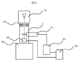
- the electron beam generated by the electron gun 51 is converged by using an electron lens 54 and irradiated onto a sample mounted on the sample stage 10. Electrons that have passed through the sample are detected by the detector 55, taken into the main controller 57 and imaged, and the sample is observed.
- the mirror body 1 is fastened to a gantry 50 that has been subjected to vibration isolation.
- the sample stage 10 receives a command from the main controller 57 and is controlled by the stage controller 53.
- the main body 1 is at a vacuum exhaust pump (not shown), is evacuated to about 10 -5 Pa.
- Patent Document 1 employs a side-entry type sample holder in a transmission electron microscope.
- the transmission electron microscope has been improved in resolution of 1 mm or less.
- One factor that hinders high-resolution observation is the vibration of the sample holder and sample stage.
- One technique for reducing the vibration of the sample holder is to increase the diameter of the sample holder.
- An object of the present invention is to provide a charged particle beam apparatus capable of safely pulling out a large-diameter sample holder from a mirror body.
- the present invention has the following configuration.
- the charged particle beam apparatus includes a holder support portion on which the sample holder is mounted, and a loader including a drive unit that drives the holder support portion.
- the charged particle beam apparatus is characterized in that the charged particle beam apparatus is introduced into and extracted from the lens body.
- the load mechanism of the sample holder makes it possible to safely pull out the large-diameter sample holder from the mirror body.
- the diameter of the sample holder can be increased, vibration of the sample holder can be suppressed, and a charged particle beam apparatus with higher measurement accuracy can be provided.
- the charged particle beam apparatus is provided with a loader described in the following examples.
- the tip of the sample holder since the tip of the sample holder has a very precise structure, it may be damaged if the sample tip contacts the sample stage or the like.
- the inlet of the sample holder to the sample stage is about 1.5 meters from the ground, and it is difficult to introduce the tip of the sample into the holder inlet so as not to touch the sample stage.
- a charged particle beam apparatus is provided with a sensor described in the following examples.
- the loader serves as a guide for introducing the sample holder so that the tip of the sample holder does not contact the inner wall of the sample stage inlet.
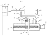
- FIG. 1 shows a schematic diagram of a transmission electron microscope including the sample holder loader 20 of the present invention.
- the loader 20 is provided on the approximate front surface of the sample stage 10.
- the loader 20 includes an arm portion and a guide rail portion that are composed of a first support portion 22 and a second support portion 23.
- the first support part 22 and the second support part 23 are semicircular and are adjusted so that the axis center of the sample holder 40 and the center of the sample inlet coincide with each other when the sample holder 40 is placed on these holder support parts. Has been.
- the sample holder 40 is installed on the first support part 22 and the second support part 23 provided in the loader. This operation is performed by an operator of the electron microscope.
- the loader and sample holder positions at this time are defined as sample replacement positions. After installing the sample holder on the support part, the sample holder is introduced into the sample inlet of the sample stage.
- FIG. 2 shows a detailed view (side view) of the loader 20.
- the sample holder feeding function of the loader is configured by a base 30 driven by a ball screw 25 having a motor 24 attached to one end.
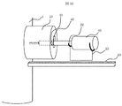
- FIG. 4 shows details of the sample holder support part.
- the first support part 22 and the second support part 23 rotate around the axis of the sample holder 40.
- the support rod of the sample holder is provided with a protrusion.
- the sample holder is mounted on the first support portion 22 and the second support portion 23, the sample holder is inserted into the holes of the protrusion 45 and the first support portion 22.
- a similar protrusion is provided in the mechanism portion of the sample holder, and the sample holder is mounted so that the holes provided in the first support portion 22 and the second support portion 23 are aligned.
- the projections 45 and the holes By coupling the projections 45 and the holes, it is possible to transmit the driving force of the loader unit to the sample holder. If it provides in both the 1st support part 22 and the 2nd support part 23, the driving force of a loader can be transmitted more stably.
- the relationship between the hole and the protrusion may be provided in reverse (that is, the protrusion is provided in the support part and the hole is provided in the sample holder).
- a curved guide rail (R guide) 29 is provided on the base 30, and the rotational force is accurately applied to the sample holder by operating the handle 28. Can be given.
- the center of curvature of the R guide 29 is attached so as to coincide with the axis center of the sample holder 40.
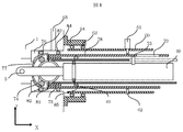
- FIG. 7 shows the details of the sample stage 10.
- the sample holder 40 carrying the observation sample is introduced from the sample insertion port of the sample stage 10.
- the spherical receiver 76 fixed to the mirror body 1 is in contact with the spherical fulcrum 77.
- the unit surrounded by the spherical fulcrum 77 and the outer cylinder 79 is called an air lock cylinder, and swings around the center of the spherical fulcrum 77.
- the sample 3 moves in the Z direction (vertical direction) and the Y direction. It is possible to move in the direction perpendicular to the page.
- the Z driving linear mechanism 61 fixed to the rotating cylinder 60 is operated.
- the Z driving linear mechanism 61 always receives a repulsive force by the Z spring 62 located on the opposite side.
- the sample holder 40 is driven in the Y direction by another linear mechanism that can be driven in a direction perpendicular to the paper surface (not shown).
- the sample holder 40 is inserted into the inner cylinder 73.
- the inside of the air lock cylinder is evacuated by a vacuum pump (not shown) connected to the air lock vacuum exhaust port 65.
- the sample holder 2 After the degree of vacuum in the inner cylinder 73 becomes approximately the same as the degree of vacuum in the mirror body 1, the sample holder 2 is rotated about the longitudinal direction. At this time, the inner cylinder 73 rotates and the valve 74 is opened by the bevel gear provided at the left end of the inner cylinder 73. Thereafter, the sample holder 40 is moved to the observation position as shown in FIG. Usually, this position is the sample observation position.
- the sample holder 40 When exchanging the sample, the sample holder 40 is pulled out from the position shown in FIG. 8 to the position shown in FIG. At this position, the sample holder 40 is rotated in the opposite direction to that when the sample holder 40 is introduced, and the air lock valve 74 is closed. When pulling out the sample holder 40, it is necessary to exert a force against the vacuum negative pressure due to the pressure difference between the vacuum side and the atmospheric side of the O-ring of the sample holder.
- the motor 24 When sending the sample holder 40 to the sample inlet, the motor 24 is driven by turning on a switch installed near the loader.
- the sample inlet is equipped with a sensor that detects that the holder has reached a specified position. This position is defined as a preliminary exhaust position.
- the position detection is performed by contact between the guide pin 42 provided on the sample holder and the sensor. When this sensor comes into contact with the guide pin, the sample holder feeding motor automatically stops. In order to stop the sample holder 40 at a specified position more safely, it is possible to provide the sensor 26 also on the guide rail portion of the loader as shown in FIGS.
- the sample holder 40 reaches the preliminary exhaust position, and the sample holder is confirmed by the sensor.
- the air lock chamber surrounded by the inner cylinder 73 of the sample stage and the air lock valve 74 is evacuated. After the air lock chamber reaches a specified pressure, the air lock valve 74 at the tip of the air lock chamber is opened.
- the air lock valve 74 is opened by rotating the inner cylinder 74 of the air lock chamber using a guide pin.
- the inner cylinder 73 and the air lock valve 74 are coupled by a bevel gear (not shown), and the rotational force about the inner cylinder axis is converted into the rotational force about the pin 81 axis to open the air lock valve 74.
- the first support portion 22 and the second support portion 23 are coupled by a protrusion 45 provided on the sample holder 40.
- the handle 28 is rotated to the angle shown in FIG. 3 by moving the handle 28 in the direction indicated by the arrow 100 in FIG.
- Rotation of the handle 28 rotates the sample holder 40 and simultaneously rotates the guide pin 42 provided in the sample holder 40.
- the inner cylinder 73 is rotated to release the air lock valve 74.
- the air lock valve 74 is closed by rotating the handle 28 in FIG. 3 in the direction B of the arrow 100 in FIG. Nitrogen is introduced into the air lock chamber to bring the air lock chamber to atmospheric pressure.
- the feeding mechanism of the loader is driven again to move to the sample holder introduction origin position.
- This method allows the sample holder to be introduced into and removed from the mirror using a loader.
- sample Holder Stocker 31 If the sample holder stocker 31 is mounted on the guide rail 21 of the loader as shown in FIG. 5, the sample holder 40 loaded with the observation sample is put on standby, and these sample holders are automatically introduced into the mirror body. It becomes possible.
- the sample holder transfer arm 32 is used to transfer the sample holder 40 to the sample holder stocker.
- the sample holder transport arm can move in the up and down direction (arrow 105 direction) and the left and right direction (arrow 104 direction) on the paper surface. 31 can be conveyed.
- the mirror body Since the mirror body is usually installed in the cover, it is necessary to open the cover door to change the sample. Since there is a temperature difference between the inside and outside of the cover, the temperature of the atmosphere inside the cover and the mirror body temperature change when the cover is opened. For this reason, a sample drift phenomenon occurs in which the visual field moves during observation due to thermal deformation accompanying temperature change. If the sample holder stocker is used, it is not necessary to open the cover door at the time of exchanging the sample, so that the sample drift can be reduced.
- the holder stocker is provided with a sensor for detecting the presence or absence of the sample holder 40, it is possible to prevent damage due to collision between the sample holders.
- a sensor using light, a touch sensor having a contact point, or the like can be considered.
- FIG. 11 shows that the sample holder 40 is at the observation position.
- the loader function in this figure includes an arm 110 that directly exerts a force on the sample holder 40, a pneumatic actuator 111 that generates a driving force, an actuator base 112, and a base 113 that is directly attached to the mirror body.
- the procedure may be performed in the reverse order of the extraction. It is desirable that the arm 110 and the sample holder 40 are not in contact after the sample holder 40 reaches the observation position.
- the pneumatic actuator base 112 is rotatable about the axis of the base 113. By rotating the arm 110, the pneumatic actuator 111, and the entire pneumatic actuator base 112 around the base 113, the arm 110 and the sample holder 40 are rotated. Can be brought into a non-contact state.
- the sample holder can be safely introduced into the mirror body. Since the tip of the sample holder can be reliably introduced into the mirror body without contacting the sample stage or the like, the adhesion of foreign matter to the tip of the holder can be reduced. Therefore, contamination during observation can be reduced. The temperature change of the mirror / sample holder can be reduced, and the sample drift during observation can be reduced.
Landscapes
- Chemical & Material Sciences (AREA)
- Analytical Chemistry (AREA)
- Analysing Materials By The Use Of Radiation (AREA)
Abstract
大口径化された試料ホルダを安全に鏡体から引き抜くことが可能な荷電粒子線装置を提供することを目的とする。サイドエントリー方式の試料ホルダ(40)が挿入される荷電粒子線装置において、前記試料ホルダ(40)が搭載されるホルダ支持部(22,23)と、前記ホルダ支持部(22,23)を駆動する駆動部を備えたローダ(20)を備え、当該ローダ(20)により前記試料ホルダ(40)の荷電粒子線装置の鏡体(1)内への導入及び引き出しを行う。
Description
本発明は、荷電粒子線装置に関し、特に、容易に試料ホルダを試料ステージに導入することが可能となる試料ホルダのローダ機構を備えた荷電粒子線装置に関する。
荷電粒子線装置の一つである、透過型電子顕微鏡(TEM)に関して図6を用いて装置構成概略を説明する。電子銃51によって生成された電子ビームを電子レンズ54を用いて収束し、試料ステージ10に搭載された試料へ照射する。試料を透過した電子を検出器55によって検出し、主制御装置57へ取り込み画像化し、試料を観察する。鏡体1は除振された架台50に締結されている。試料ステージ10は主制御装置57からの指令を受け、ステージコントローラ53にて制御する。鏡体1は図示しない真空排気用ポンプにて、10-5Pa程度まで真空排気される。
透過型電子顕微鏡電子顕微鏡においては、サイドエントリー方式の試料ホルダが採用されている。特許文献1は透過型電子顕微鏡にサイドエントリー方式の試料ホルダを採用したものである。
近年、透過型電子顕微鏡では、1Å以下の高分解能化が進んでいる。高分解能観察を阻害する要因の一つが試料ホルダ・試料ステージの振動である。試料ホルダを低振動化する一つの手法が 試料ホルダの大口径化である。
しかし、試料ホルダを大口径化すると、鏡体1から試料ホルダ40を引く抜く際に必要とされる真空負圧に対抗する力も増大するという問題も発生する。
本発明は、大口径化された試料ホルダを安全に鏡体から引き抜くことが可能な荷電粒子線装置を提供することを目的とする。
上記課題に鑑み、本発明は以下の構成を備える。サイドエントリー方式の試料ホルダが挿入される荷電粒子線装置において、前記試料ホルダが搭載されるホルダ支持部と、前記ホルダ支持部を駆動する駆動部を備えたローダを備え、当該ローダにより前記試料ホルダの荷電粒子線装置の鏡体内への導入及び引き出しを行うことを特徴とする荷電粒子線装置。
試料ホルダのロード機構により、大口径化された試料ホルダを安全に鏡体から引き抜くことが可能となる。また、これにより試料ホルダの大口径化が実現できるので、試料ホルダの振動を抑制することができ、より測定精度の高い荷電粒子線装置を提供することができる。
まず、実施例を説明する前に、本発明の概要を述べる。
試料ホルダ軸の大口径化により試料ホルダを鏡体から引き抜く際に必要な力も大きくなる。TEMでは、試料ホルダの位置は床面から1.5メートル以上程度であり、大口径化された試料ホルダを安全に鏡体から引き抜くことが困難になっている。これに対し、本発明では、下記実施例で説明するローダを荷電粒子線装置に備えた。
次に、試料ホルダの先端は、非常に精密な構造であるため、試料先端が試料ステージ等へ接触すると破損する場合がある。上記課題で記載したように試料ホルダの試料ステージへの投入口は地上から1.5メートル程度であり、試料の先端を試料ステージに触れないようにホルダ投入口へ導入することが困難である。これに対し、本発明では、下記実施例で説明するセンサを荷電粒子線装置に備えた。
さらに、鏡体はカバー内に設置されているため、試料交換するためにはカバーの扉を開ける必要がある。カバーをあけるとカバー内雰囲気の温度および鏡体温度が変化する。このため、温度変化に伴う熱変形によって観察中に視野が移動する試料ドリフト現象が生じる。これに対し、本発明では、下記実施例で説明する試料ホルダストッカーを備えた。
そして、試料ホルダ先端への異物の付着はコンタミネーションの要因となる。試料ホルダの導入時に試料ステージ投入口の内壁に試料ホルダ先端部が接触すると、異物が付着する場合がある。これに対し、本発明では、上記のローダが試料ホルダを導入するためのガイドの役割をし、試料ホルダ先端部が試料ステージ投入口の内壁に接触しないようにした。
以下、図面を用いて説明していく。
<本発明の試料ホルダローダ機能を備える電子顕微鏡全体の概略図>図1に本発明の試料ホルダローダ20を備えた透過型電子顕微鏡の概略図を示す。ローダ20は試料ステージ10の概略前面に備えられる。ローダ20は、第1支持部22と第2支持部23から構成されるアーム部とガイドレール部を備えている。
第1支持部22と第2支持部23は、半円形状でこれらのホルダ支持部に試料ホルダ40を置いたときに、試料ホルダ40の軸中心と試料投入口の中心が一致するように調整されている。
試料ホルダ40を鏡体1に導入する手順について説明する。試料ホルダ40をローダに備えられた第1支持部22および第2支持部23上に設置する。この作業は、電子顕微鏡の操作者が行う。この時のローダ及び試料ホルダ位置を試料交換位置と定義する。
支持部へ試料ホルダを設置した後、試料ホルダを試料ステージの試料投入口へ導入する。
支持部へ試料ホルダを設置した後、試料ホルダを試料ステージの試料投入口へ導入する。
<ローダ部の詳細構造>図2にローダ20の詳細図(側面図)を示す。ローダの試料ホルダ送り機能は、一端にモータ24が取り付けられたボールネジ25によって駆動されるベース30にて構成されている。
<支持部の詳細構造>図4に試料ホルダ支持部の詳細を示す。第1支持部22および第2支持部23は試料ホルダ40の軸を中心に回転運動をする。支持部の移動、回転等の駆動力を伝えるために、試料ホルダの支持棒には突起が備えられている。試料ホルダを第1支持部22および第2支持部23に搭載するときには、突起部45と第1支持部22の穴に挿入する。試料ホルダの機構部にも同様の突起部が備えられており、第1支持部22及び第2支持部23に設けられた穴を一致させるように、試料ホルダを搭載する。これらの突起部45と穴の結合によって、ローダ部の駆動力を試料ホルダへ伝えることが可能となる。第1支持部22及び第2支持部23両方に設ければより安定してローダの駆動力を伝達できる。なお、穴と突起の関係は逆に設けられて(つまり、突起部が支持部に、穴が試料ホルダに設けられて)いてもよい。
<支持部の回転機構>図3の断面図に示すように、ベース30上には曲線型のガイドレール(Rガイド)29が備えられ、ハンドル28を操作することにより試料ホルダへ正確に回転力を与えることができる。Rガイド29の曲率中心は、試料ホルダ40の軸中心と一致するように取り付けられている。
<ローダの設置場所>図1ではローダを荷重板2上に設置する場合を説明したが、図10のように鏡体1に設置してもよい。また、荷重板を支持する架台にローダを取り付けてもよい。
試料ホルダの導入手順について説明する。まず、試料ホルダの導入部の詳細機構について説明する。
図7に試料ステージ10の詳細を示す。観察試料を搭載した試料ホルダ40は、試料ステージ10の試料投入口から導入する。鏡体1に固定された球面受け76は球形支点77と接触している。球形支点77と外筒79で囲まれたユニットはエアーロックシリンダと呼ばれ、球形支点77の中心を軸として首振り運動をし、その結果として、試料3をZ方向(鉛直方向)およびY方向(紙面垂直方向)に移動させることが可能となる。試料Z方向に駆動させるためには、回転筒60に固定されたZ駆動用リニア機構61を動作させる。Z駆動用リニア機構61は、その対面に位置したZバネ62によって常に反発力を受ける。図示しない紙面に垂直方向に駆動可能な別のリニア機構によってY方向へ試料ホルダ40を駆動する。
試料ホルダ40を鏡体1内へ導入する動作について説明する。まず試料ホルダ40を内筒73内へ挿入する。この状態でエアーロック真空排気ポート65に接続された図示しない真空ポンプにてエアーロックシリンダ内を真空排気する。
内筒73内の真空度が鏡体1内の真空度と同程度になった後、試料ホルダ2の長手方向を軸として回転させる。このとき、内筒73が回転し、内筒73の左端に備えられた傘歯車によってバルブ74を開ける。その後、図8に示したように試料ホルダ40を観察位置まで移動させる。通常この位置が、試料観察位置である。
試料交換をする場合には、試料ホルダ40は図8の位置から図7に示された位置まで引き抜く。この位置で試料ホルダ40導入時とは逆向きに試料ホルダ40を回転させ、エアーロックバルブ74を閉じる。試料ホルダ40を引き抜くときは、試料ホルダのOリングの真空側と大気側の圧力差による真空負圧に対抗して力を及ぼす必要がある。
<試料ホルダの鏡体への導入>次に、本発明の試料導入ステップについて説明する。
試料ホルダ40を試料投入口へ送る場合には、ローダ付近に設置されたスイッチをいれることによりモータ24を駆動する。
試料投入口には、センサが備えられており、ホルダが規定の位置まで到達したことを検知する。この位置を予備排気位置と定義する。位置検知は、試料ホルダに備えられたガイドピン42とセンサの接触によって行われる。このセンサとガイドピンが接触したときに、自動で試料ホルダ送り用のモータが停止する。より安全に試料ホルダ40を規定の位置で停止させるためには、図2および図3に示すようにローダのガイドレール部にもセンサ26を設けることも可能である。
図9に示すように予備排気位置まで試料ホルダ40が到達し、センサにて試料ホルダを確認したと同時に試料ステージの内筒73とエアーロックバルブ74で囲まれたエアーロック室を真空排気する。エアーロック室内が規定の圧力になった後、エアーロック室先端のエアーロックバルブ74を開ける。
次に、上記エアーロックバルブを解放する作業を本発明のローダを用いて実施した場合について説明する。エアーロックバルブ74を開けるためには、ガイドピンを用いてエアーロック室の内筒74を回転させることによって行われる。内筒73とエアーロックバルブ74は図示しない傘歯車によって結合されており、内筒軸中心の回転力をピン81軸中心の回転力に変換し、エアーロックバルブ74を開く。
図4に示したように第1支持部22と第2支持部23は、試料ホルダ40に備えられた突起45で結合されている。ハンドル28を図5の矢印100のA方向へ移動させることにより図3の角度までハンドル28を回転させる。
ハンドル28の回転は、試料ホルダ40を回転させ、同時に試料ホルダ40に備えられたガイドピン42を回転させる。これにより内筒73を回転させエアーロックバルブ74を解放する。
<エアーロックバルブ解放後のホルダ駆動>エアーロックバルブ74を解放後、ローダのモータを駆動して試料ホルダ40を観察位置まで駆動する。
<ハンドルの試料ホルダからの切り離し>観察位置まで試料ホルダを移動させた後、試料ホルダ40と第1支持部22、第2支持部23を切り離す。ハンドル28をハンドル軸方向に移動可能な構造となっている。ハンドル28を矢印101のC方向に移動させて切り離す。
<試料ホルダの鏡体からの引き抜き>観察が完了した後、試料ホルダを鏡体から引き抜く動作について説明する。第1支持部22と第2支持部23を試料ホルダ40と接続する。次にローダ20に備えられたモータ24を駆動して試料ホルダ40を予備排気位置まで移動させる。
次に図3中のハンドル28を図5中の矢印100のB方向に回転させることにより、エアーロックバルブ74を閉じる。エアーロック室に窒素を導入して、エアーロック室を大気圧にする。ローダの送り機構を再度駆動して、試料ホルダ導入原点位置まで移動する。
このような手法により、ローダを用いて試料ホルダの鏡体への導入、引き抜きが出来るようになる。
<試料ホルダストッカー>図5に示すようにローダのガイドレール21に試料ホルダストッカー31を搭載すれば、観察試料を搭載した試料ホルダ40を待機させ、これらの試料ホルダを自動で鏡体に導入することが可能となる。
試料ホルダ40の試料ホルダストッカーへの搬送は、試料ホルダ搬送アーム32を用いる。試料ホルダ搬送アームは紙面上下方向(矢印105方向)および左右方向(矢印104方向)に移動でき、試料ホルダ第1支持部22および第2支持部23に搭載されている試料ホルダ40を試料ホルダストッカー31に搬送することが可能である。
通常鏡体はカバー内に設置されているため、試料交換するためにはカバーの扉を開ける必要がある。カバー内外は温度差があるため、カバーをあけるとカバー内雰囲気の温度および鏡体温度が変化する。このため、温度変化に伴う熱変形によって観察中に視野が移動する試料ドリフト現象が生じる。試料ホルダストッカーを用いれば、試料交換時にカバーの扉を開ける必要がなくなるため、試料ドリフトを低減することが可能となる。
なお、自動で試料ホルダ40を鏡体1へ導入するためには、モータを用いてハンドルを回転させる必要がある。
<ホルダストッカーでのホルダ衝突防止機能>ホルダストッカーには、試料ホルダ40の有無を検知するセンサを備えると、試料ホルダ同士の衝突による破損を防止することが可能である。センサは、光を用いたセンサや接点を有するタッチセンサなどが考えられる。
<エアーシリンダを用いたローダ>以上では電動アクチュエータを用いたローダ機能について説明したが、以下では空圧アクチュエータを用いた場合の簡易なローダ機能の実施例について説明する。
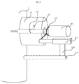
図11は、試料ホルダ40は観察位置にある。本図でのローダ機能は、試料ホルダ40に力を直接及ぼすアーム110、駆動力を発生する空圧アクチュエータ111、アクチュエータベース112、鏡体に直接取り付けられたベース113で構成されている。
試料交換時に試料ホルダ40を鏡体1から引き抜く必要があるが、引き抜くためには真空負圧に抗する力が必要である。引き抜く際にはアーム110を試料ホルダ40の段差に突き当て、空圧シリンダ110のを縮めることにより、試料ホルダ40を予備排気位置まで引き抜く。その後、TEM操作者が試料ホルダを回転させ、エアーロックバルブを閉じた後、試料ホルダ40を鏡体1から完全に引き抜く。
試料ホルダ40を鏡体1に導入する場合は、引き抜く場合と逆の手順で行えばよい。観察位置に試料ホルダ40が到達した後は、アーム110と試料ホルダ40は、接触していない状態が望ましい。空圧アクチュエータベース112はベース113の軸中心に回転可能となっており、ベース113を軸にアーム110、空圧アクチュエータ111、空圧アクチュエータベース112全体を回転させることにより、アーム110と試料ホルダ40を非接触状態とすることができる。
上記の各実施例によれば、試料ホルダを安全に鏡体へ導入することが可能となる。試料ホルダ先端を試料ステージ等に接触させることなく確実に鏡体に導入することができるため、ホルダ先端への異物の付着を低減することができる。そのため、観察時のコンタミネーションを低減することができる。鏡体/試料ホルダの温度変化を小さくし、観察時の試料ドリフトを低減することができる。
1…鏡体、2…荷重板、10…試料ステージ、20…ローダ、21…ガイドレール、22…第1支持部、23…第2支持部、24…モータ、25…ボールネジ、26…センサ、27…位置検知板、28…ハンドル、29…Rガイド、30…ベース、31…試料ホルダストッカー、32…試料ホルダ搬送アーム、40…試料ホルダ、41…ホルダ用Oリング、42…ガイドピン、43…試料、44…支持棒、45…突起1、50…架台、51…電子銃、53…ステージ用コントローラ、54…電子レンズ、55…検出器、57…主制御装置、60…回転筒、61…Z駆動用リニア機構、62…Zバネ、63…ベアリング、64…ベース、65…エアーロック真空排気ポート、73…内筒、74…エアーロックバルブ1、75…バルブ固定部、76…球面受け、77…球形支点、78…外筒、79…ホルダガイド溝、81…ピン、82…エアーロックバルブ用Oリング、83…球形支点用Oリング1、84…球形支点用Oリング2、100…ハンドル回転方向、101…ハンドル伸縮方向、102…試料ホルダ水平移動用ステージ、103…試料ホルダ垂直移動用ステージ、110…アーム、111…空圧アクチュエータ、112…空圧アクチュエータベース、113…ベース
Claims (11)
- サイドエントリー方式の試料ホルダが挿入される荷電粒子線装置において、
前記試料ホルダが搭載されるホルダ支持部と、前記ホルダ支持部を駆動する駆動部を備えたローダを備え、
当該ローダにより前記試料ホルダの荷電粒子線装置の鏡体内への導入及び引き出しを行うこと
を特徴とする荷電粒子線装置。 - 請求項1の荷電粒子線装置において、
前記試料ホルダはガイドピンを備え、
前記ガイドピンにより前記荷電粒子線装置に設けられた予備排気室のバルブの開閉を行うことを特徴とする荷電粒子線装置。 - 請求項2の荷電粒子線装置において、
前記ローダは回転機構を備え、前記試料ホルダを当該回転機構により前記ガイドピンを駆動し、前記予備排気室のバルブの開閉を行うこと
を特徴とする荷電粒子線装置。 - 請求項1の荷電粒子線装置において、
前記ローダは回転機構を備え、前記回転機構により前記試料ホルダの軸中心に回転することを特徴とする荷電粒子線装置。 - 請求項1の荷電粒子線装置において、
前記ホルダ支持部と前記試料ホルダには、互いに固定する固定部が設けられていることを特徴とする荷電粒子線装置。 - 請求項1の荷電粒子線装置において、
前記支持部は前記試料ホルダを鉛直方向に駆動が可能であることを特徴とする荷電粒子線装置。 - 請求項1の荷電粒子線装置において、
前記ローダは、前記試料ホルダの位置を認識する位置センサを備えたことを特徴とする荷電粒子線装置。 - 請求項1の荷電粒子線装置において、
前記ローダは前記試料ホルダを複数備えるホルダストッカーを有することを特徴とする荷電粒子線装置。 - 請求項8の荷電粒子線装置において、
前記ホルダストッカーは、前記試料ホルダの有無を判断するセンサを備えたこと
を特徴とする荷電粒子線装置。 - 請求項1の荷電粒子線装置において、
前記ローダは、試料ホルダを駆動する空圧アクチュエータを備えたこと
を特徴とする荷電粒子線装置。 - 請求項1の荷電粒子線装置において、
前記ローダは、前記荷電粒子線装置の鏡体に固定されていること
を特徴とする荷電粒子線装置。
Applications Claiming Priority (2)
| Application Number | Priority Date | Filing Date | Title |
|---|---|---|---|
| JP2013153168A JP6286146B2 (ja) | 2013-07-24 | 2013-07-24 | 荷電粒子線装置 |
| JP2013-153168 | 2013-07-24 |
Publications (1)
| Publication Number | Publication Date |
|---|---|
| WO2015011967A1 true WO2015011967A1 (ja) | 2015-01-29 |
Family
ID=52393024
Family Applications (1)
| Application Number | Title | Priority Date | Filing Date |
|---|---|---|---|
| PCT/JP2014/063010 Ceased WO2015011967A1 (ja) | 2013-07-24 | 2014-05-16 | 荷電粒子線装置 |
Country Status (2)
| Country | Link |
|---|---|
| JP (1) | JP6286146B2 (ja) |
| WO (1) | WO2015011967A1 (ja) |
Cited By (1)
| Publication number | Priority date | Publication date | Assignee | Title |
|---|---|---|---|---|
| JP2023182490A (ja) * | 2022-06-14 | 2023-12-26 | 株式会社Anmic | 大気遮断装置及び大気非暴露搬送方法 |
Families Citing this family (1)
| Publication number | Priority date | Publication date | Assignee | Title |
|---|---|---|---|---|
| KR102118266B1 (ko) * | 2018-10-25 | 2020-06-03 | 한국기초과학지원연구원 | Tem 시료 지지 장치 |
Citations (4)
| Publication number | Priority date | Publication date | Assignee | Title |
|---|---|---|---|---|
| JPH08124508A (ja) * | 1994-10-20 | 1996-05-17 | Jeol Ltd | 電子顕微鏡用試料保持装置 |
| JPH10199466A (ja) * | 1997-01-13 | 1998-07-31 | Hitachi Ltd | イオンビーム加工観察装置 |
| JP2000146781A (ja) * | 1998-11-18 | 2000-05-26 | Hitachi Ltd | 試料解析方法、試料作成方法およびそのための装置 |
| JP2005327710A (ja) * | 2004-04-16 | 2005-11-24 | Hitachi High-Technologies Corp | 荷電粒子線装置及び試料ホルダ |
Family Cites Families (4)
| Publication number | Priority date | Publication date | Assignee | Title |
|---|---|---|---|---|
| JPS60156658U (ja) * | 1984-03-29 | 1985-10-18 | 日本電子株式会社 | 試料装着装置 |
| JP2000182561A (ja) * | 1998-12-14 | 2000-06-30 | Hitachi Ltd | 電子線描画装置 |
| JP4063503B2 (ja) * | 2001-04-10 | 2008-03-19 | 日本電子株式会社 | 電子顕微鏡 |
| JP2014038786A (ja) * | 2012-08-20 | 2014-02-27 | Hitachi High-Technologies Corp | 荷電粒子線装置及び試料移動装置 |
-
2013
- 2013-07-24 JP JP2013153168A patent/JP6286146B2/ja active Active
-
2014
- 2014-05-16 WO PCT/JP2014/063010 patent/WO2015011967A1/ja not_active Ceased
Patent Citations (4)
| Publication number | Priority date | Publication date | Assignee | Title |
|---|---|---|---|---|
| JPH08124508A (ja) * | 1994-10-20 | 1996-05-17 | Jeol Ltd | 電子顕微鏡用試料保持装置 |
| JPH10199466A (ja) * | 1997-01-13 | 1998-07-31 | Hitachi Ltd | イオンビーム加工観察装置 |
| JP2000146781A (ja) * | 1998-11-18 | 2000-05-26 | Hitachi Ltd | 試料解析方法、試料作成方法およびそのための装置 |
| JP2005327710A (ja) * | 2004-04-16 | 2005-11-24 | Hitachi High-Technologies Corp | 荷電粒子線装置及び試料ホルダ |
Cited By (2)
| Publication number | Priority date | Publication date | Assignee | Title |
|---|---|---|---|---|
| JP2023182490A (ja) * | 2022-06-14 | 2023-12-26 | 株式会社Anmic | 大気遮断装置及び大気非暴露搬送方法 |
| JP7525761B2 (ja) | 2022-06-14 | 2024-07-31 | 株式会社Anmic | 大気遮断装置及び大気非暴露搬送方法 |
Also Published As
| Publication number | Publication date |
|---|---|
| JP6286146B2 (ja) | 2018-02-28 |
| JP2015023011A (ja) | 2015-02-02 |
Similar Documents
| Publication | Publication Date | Title |
|---|---|---|
| US7041985B1 (en) | Manipulator for microscopy sample preparation and methods for making and use thereof | |
| CN105628978B (zh) | 超高真空样品转移设备及转移方法 | |
| NL2020235B1 (en) | Vacuum transfer assembly | |
| KR102646113B1 (ko) | 집속 이온 빔 장치 | |
| KR20180109688A (ko) | 하전 입자 빔 장치 | |
| JP5351634B2 (ja) | 電子線装置 | |
| WO2014030425A1 (ja) | 電子顕微鏡及び試料移動装置 | |
| JP7125786B2 (ja) | 自動マルチグリッドハンドリング装置 | |
| JP6286146B2 (ja) | 荷電粒子線装置 | |
| US7923702B2 (en) | System and method for processing an object | |
| US7531816B2 (en) | Vacuum conveying apparatus and charged particle beam equipment with the same | |
| CN211318266U (zh) | 一种用于跨平台连接的样品密封和真空转移装置 | |
| JP5875500B2 (ja) | 電子ビーム顕微装置 | |
| EP3032564A1 (en) | Improved cryogenic specimen holder for a charged particle microscope | |
| CN119881380B (zh) | 用于超高真空磁力显微镜的传样装置及传样方法 | |
| US11753254B2 (en) | Transport apparatus and method for transferring a sample between two devices, and system for sample manipulation | |
| EP2784797B1 (en) | Sample introduction device and charged particle beam instrument | |
| CN114334760B (zh) | 样品传输装置及半导体设备 | |
| EP4032612B1 (en) | System and method for inserting a sample into a chamber | |
| JP2002334677A (ja) | 試料交換装置 | |
| JP6196878B2 (ja) | 電子顕微鏡 | |
| JP2015103431A (ja) | 試料導入装置および荷電粒子線装置 | |
| CN114334762B (zh) | 一种样品传输装置及半导体设备 | |
| JP2007287546A (ja) | 真空容器及び電子線装置 | |
| CN220340917U (zh) | 一种用于放射源的管道输送装置 |
Legal Events
| Date | Code | Title | Description |
|---|---|---|---|
| 121 | Ep: the epo has been informed by wipo that ep was designated in this application |
Ref document number: 14828847 Country of ref document: EP Kind code of ref document: A1 |
|
| NENP | Non-entry into the national phase |
Ref country code: DE |
|
| 122 | Ep: pct application non-entry in european phase |
Ref document number: 14828847 Country of ref document: EP Kind code of ref document: A1 |