WO2015011806A1 - 組立機、保持部材、および検査治具 - Google Patents
組立機、保持部材、および検査治具 Download PDFInfo
- Publication number
- WO2015011806A1 WO2015011806A1 PCT/JP2013/070097 JP2013070097W WO2015011806A1 WO 2015011806 A1 WO2015011806 A1 WO 2015011806A1 JP 2013070097 W JP2013070097 W JP 2013070097W WO 2015011806 A1 WO2015011806 A1 WO 2015011806A1
- Authority
- WO
- WIPO (PCT)
- Prior art keywords
- component
- holding member
- assembly
- gel
- electronic component
- Prior art date
- Legal status (The legal status is an assumption and is not a legal conclusion. Google has not performed a legal analysis and makes no representation as to the accuracy of the status listed.)
- Ceased
Links
Images



Classifications
-
- H—ELECTRICITY
- H05—ELECTRIC TECHNIQUES NOT OTHERWISE PROVIDED FOR
- H05K—PRINTED CIRCUITS; CASINGS OR CONSTRUCTIONAL DETAILS OF ELECTRIC APPARATUS; MANUFACTURE OF ASSEMBLAGES OF ELECTRICAL COMPONENTS
- H05K13/00—Apparatus or processes specially adapted for manufacturing or adjusting assemblages of electric components
- H05K13/04—Mounting of components, e.g. of leadless components
- H05K13/0404—Pick-and-place heads or apparatus, e.g. with jaws
- H05K13/0408—Incorporating a pick-up tool
- H05K13/0409—Sucking devices
Definitions
- the present invention relates to an assembling machine for transferring parts from a supply position to an assembling position and assembling the parts to an assembly, and a holding member and an inspection jig used in the assembling machine.
- the assembly machine is used as a manufacturing equipment for assembling a component mounting machine that mounts a plurality of electronic components on a circuit board to produce an electronic circuit product, or a power module.
- a component mounting machine Patent Document 1 discloses that an electronic component at a component supply position is sucked by supplying a negative pressure to a suction nozzle that is a holding member, and the electronic component is mounted at a component assembly position (circuit).
- a configuration for mounting at a predetermined coordinate position on a substrate is disclosed.
- Patent Document 2 discloses a configuration in which an electronic component is gripped by a plurality of gripping claws of the chuck device using the chuck device as a holding member.
- the moving speed of the holding member that holds the parts may be set to be higher. Therefore, the holding member in the assembling machine is required to reliably hold the target part. Further, the inspection jig in the assembly machine is required to reliably hold the part even if the target part is fine in the precision inspection of the assembly control.
- the present invention has been made in view of such circumstances, and an assembly machine that can cope with downsizing of a product and shortening of cycle time by securely holding a target part, and a holding member used in the assembly machine And an inspection jig.
- An assembling machine is a holding member that acquires and holds a component supplied to a supply position, and can change an adhesive force in accordance with an applied voltage in at least a part of a range in contact with the component.
- the holding member in which ER gel is used, the transfer device that supports the holding member so that the component held by the holding member can be transferred to the assembly position in the positioned assembly, and the holding member And a control device for controlling the voltage applied to the ER gel when the holding member holds the component.
- a voltage is appropriately applied to the ER gel so that the holding member can be held.
- a holding member can improve holding force only the part of the adhesive force according to an applied voltage, when the ER gel to which the voltage was applied contacts the component made into a holding object. Therefore, even if the target part is fine, it is possible to hold the part with certainty, and it is possible to adapt to increase in the moving speed. Therefore, it is possible to cope with the downsizing of the product and to shorten the cycle time.
- the holding member according to claim 7 is used in an assembly machine that transfers the component acquired at the supply position to the assembly position and assembles the component to the assembly target, and acquires the component supplied to the supply position.
- An ER gel that can change the adhesive force according to the applied voltage is used in at least a part of the range of the holding member that holds the component.
- the holding member when the holding member holds the component, the ER gel to which a voltage is applied comes into contact with the component, so that the holding force can be improved by an amount corresponding to the adhesive force according to the applied voltage. Therefore, even if the target part is fine, the part can be reliably held, and the moving speed can be increased. Therefore, the application of the holding member to an assembly machine that requires a reduction in product size or a reduction in cycle time is particularly useful.
- the inspection jig according to claim 10 transfers the component acquired at the supply position to the assembly position, and transfers the held component to the assembly position in an assembly machine for assembling the component to the assembly target.
- An inspection jig that is used for accuracy inspection of assembly control and that mounts the component or a pseudo component for inspection in place of the assembly target in the accuracy inspection, wherein the component or the pseudo component is mounted
- the assembly position is provided with an adhesive sheet formed of ER gel capable of varying the adhesive force according to the applied voltage.
- the inspection jig when the inspection jig holds the component or the pseudo-component, the component placed by the adhesive force corresponding to the applied voltage is caused by the pressure-sensitive adhesive sheet coming into contact with the component. Can be held. Therefore, even if the target component is fine, the component can be reliably held. Further, when the accuracy inspection is finished, the holding state of the component or the pseudo component can be released by releasing the application of the voltage to the adhesive sheet. Therefore, it is possible to simplify the collection of the parts used for the accuracy inspection. Therefore, it is particularly useful to apply the inspection jig to an assembly machine that requires a reduction in product size.
- FIG. 1 is an overall view showing a component mounter in a first embodiment. It is a block diagram which shows the control apparatus of a component mounting machine. It is an enlarged view which shows the suction nozzle in FIG. It is sectional drawing which shows the structure of the front-end
- the assembly machine exemplifies a configuration that is a component mounting machine for circuit board products produced by mounting electronic components on a circuit board (an assembly target).
- the component mounter is a device that mounts a plurality of electronic components on a circuit board, for example, in an integrated circuit manufacturing process.
- the circuit board is applied with cream solder at a mounting position (assembly position) of an electronic component by, for example, a screen printing machine, and sequentially transported through a plurality of component mounting machines to mount the electronic component. Thereafter, the circuit board on which the electronic component is mounted is transported to a reflow furnace and soldered to constitute an integrated circuit as a circuit board product.
- the component mounter 1 includes a substrate transfer device 10, a component supply device 20, a component transfer device 30, a component camera 50, a substrate camera 60, and a control device 70.
- the devices 10, 20, 30 and the cameras 50, 60 are provided on the base 2 of the component mounter 1 and are controlled by the control device 70.
- the horizontal direction of the component mounter 1 (direction from the upper left to the lower right in FIG. 1) is the X-axis direction
- the horizontal longitudinal direction of the component mounter 1 from the upper right to the lower left in FIG. 1).
- the direction of heading is the Y-axis direction
- the vertical height direction vertical direction in FIG. 1) is the Z-axis direction.
- the board transfer device 10 transfers the circuit board B in the X-axis direction and positions the circuit board B at a predetermined position.
- substrate conveyance apparatus 10 is a double conveyor type comprised by the some conveyance mechanism 11 arranged in parallel by the Y-axis direction.
- the transport mechanism 11 carries the circuit board B to a predetermined position in the X-axis direction by a conveyor belt, and clamps the circuit board B by a clamp device. Then, when an electronic component is mounted on the circuit board B, the transport mechanism 11 unclamps the circuit board B and carries the circuit board B out of the component mounting machine 1.
- the transport mechanism 11 uses ER gel in at least a part of the range in contact with the circuit board B in the above-described clamping device. That is, when positioning the circuit board B, the clamping device is configured to hold the circuit board B with the adhesive force of the ER gel that varies according to the voltage applied to the ER gel in addition to the original clamping force.
- the detailed configuration of the clamping device of the transport mechanism 11 will be described later.
- the component supply device 20 is a device that supplies electronic components mounted on the circuit board B.
- the component supply device 20 is disposed on the front side in the Y-axis direction of the component mounter 1 (lower left side in FIG. 1).
- the component supply apparatus 20 is a feeder system that uses a plurality of cassette-type feeders 21.
- the feeder 21 includes a feeder main body portion 21a that is detachably attached to the base 2, and a reel housing portion 21b that is provided on the rear end side of the feeder main body portion 21a.
- the feeder 21 holds a supply reel 22 around which a component packaging tape is wound by a reel accommodating portion 21b.
- the above-described component packaging tape includes a carrier tape in which electronic components are stored at a predetermined pitch, and a top tape that is bonded to the upper surface of the carrier tape and covers the electronic components.
- the feeder 21 pitch feeds the component packaging tape drawn from the supply reel 22 by a pitch feed mechanism (not shown).
- the feeder 21 peels the top tape from the carrier tape to expose the electronic component.
- the feeder 21 supplies the electronic component so that the suction nozzle 42 of the component transfer device 30 can suck the electronic component at the component supply position Ps located on the front end side of the feeder main body 21a.
- the component transfer device 30 is a device that transfers electronic components from the component supply position Ps to the mounting position of the circuit board B.
- the component transfer device 30 is an orthogonal coordinate type disposed above the substrate transfer device 10 and the component supply device 20.
- a Y-axis moving table 32 is provided on a pair of Y-axis rails 31 extending in the Y-axis direction so as to be movable in the Y-axis direction.
- the Y-axis moving table 32 is controlled by the operation of the Y-axis motor 33 via a ball screw mechanism.
- the Y-axis moving table 32 is provided with an X-axis moving table 34 that can move in the X-axis direction.
- the X-axis moving table 34 is controlled by the operation of the X-axis motor 35 via a ball screw mechanism (not shown).
- a component mounting head 40 is attached to the X-axis moving table 34.
- the component mounting head 40 supports a plurality of suction nozzles 42 so as to be movable up and down by a nozzle holder 41 that can rotate around an R axis parallel to the Z axis.
- the component mounting head 40 is fixed to the X axis moving table 34 via a frame 43.
- the nozzle holder 41 is connected to the output shaft of the R-axis motor 44 and is configured to be rotationally controlled by the R-axis motor 44.
- the suction nozzle 42 is controlled to move in the Z-axis direction by an elevating mechanism including a Z-axis motor 45 and the like, and the rotation angle is controlled by a rotational drive of a ⁇ -axis motor (not shown).
- the suction nozzle 42 constitutes a suction mechanism in the component mounting head 40 and can suck electronic components by the supplied negative pressure. Furthermore, in this embodiment, the suction nozzle 42 uses ER gel in at least a part of a range in contact with the electronic component at the tip of the suction nozzle 42. That is, when the electronic nozzle is held, the suction nozzle 42 holds the electronic component with the adhesive force of the ER gel that varies according to the applied voltage to the ER gel in addition to the original negative pressure suction force. Yes. A detailed configuration of the suction nozzle 42 will be described later.
- the component camera 50 and the substrate camera 60 are digital imaging devices having imaging elements such as CCD (Charge Coupled Device) and CMOS (Complementary Metal Oxide Semiconductor).
- the component camera 50 and the board camera 60 capture an image within a range that can be accommodated in the camera field of view based on a control signal from the control device 70 that is communicably connected, and send the image data acquired by the imaging to the control device 70.
- the component camera 50 is fixed to the base 2 so that the optical axis is in the Z-axis direction, and is configured to be able to image an electronic component held by the suction nozzle 42.
- the control device 70 that has acquired the image data from the component camera 50 recognizes the holding state of the electronic component by the suction nozzle 42 by image processing. As described above, it is possible to improve the accuracy of mounting control by correcting the position and angle of the suction nozzle 42 according to the holding state of the electronic component.
- the board camera 60 is fixed to the X-axis moving base 34 so that the optical axis is in the Z-axis direction, and is configured to be able to image the circuit board B.
- the control device 70 that has acquired the image data from the substrate camera 60 recognizes the positioning state of the circuit board B by the substrate transfer device 10 by recognizing, for example, a substrate mark attached to the substrate by image processing. Then, the control device 70 corrects the positions of the Y-axis moving table 32 and the X-axis moving table 34 in accordance with the positioning state of the circuit board B, and controls so as to mount the electronic component. As described above, by using the image data obtained by the board camera 60, it is possible to improve the accuracy of the mounting control.
- the control device 70 is mainly configured by a CPU, various memories, and a control circuit, and controls the mounting of electronic components on the circuit board B based on image data acquired by imaging by the component camera 50 and the board camera 60.
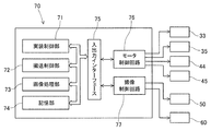
- an input / output interface 75 is connected to a mounting control unit 71, a conveyance control unit 72, an image processing unit 73, and a storage unit 74 via a bus.
- a motor control circuit 76 and an imaging control circuit 77 are connected to the input / output interface 75.
- the mounting control unit 71 controls the position of the component mounting head 40 and the operation of the suction mechanism via the motor control circuit 76. More specifically, the mounting control unit 71 inputs information output from various sensors provided in the component mounting machine 1 and results of various recognition processes. The mounting control unit 71 then sends a control signal to the motor control circuit 76 based on the control program stored in the storage unit 74, information from various sensors, and the results of image processing and recognition processing. Thereby, the position and rotation angle of the suction nozzle 42 supported by the component mounting head 40 are controlled. In addition, the mounting control unit 71 adjusts the supply of negative pressure to the suction nozzle 42 by the pump of the suction mechanism of the component mounting head 40 and the voltage applied to the ER gel of the suction nozzle 42, so Control the holding state of parts.
- the conveyance control unit 72 controls the conveyance of the circuit board B by the substrate conveyance device 10 and the operation of the clamping device. Further, when the clamping device clamps and unclamps the circuit board B, the conveyance control unit 72 adjusts the voltage applied to the ER gel provided in the clamping device, thereby holding the circuit board B by the clamping device. To control.
- the image processing unit 73 acquires image data obtained by imaging the component camera 50 and the board camera 60 via the imaging control circuit 77, and executes image processing according to the application. This image processing includes, for example, processing such as binarization of image data, filtering, and hue extraction.
- the storage unit 74 is configured by an optical drive device such as a hard disk device or a flash memory.
- a control program for operating the component mounting machine 1 image data transferred from the component camera 50 and the board camera 60 to the control device 70 via a bus or a communication cable, and processing by the image processing unit 73 Temporary data and the like are stored.
- the input / output interface 75 is interposed between the CPU and storage unit 74 and the control circuits 76 and 77, and adjusts data format conversion and signal strength.
- the motor control circuit 76 controls the Y-axis motor 33, the X-axis motor 35, the R-axis motor 44, the Z-axis motor 45, and the ⁇ -axis motor based on the control signal from the mounting control unit 71.
- the component mounting head 40 is positioned in each axial direction, and the suction nozzle 42 is controlled to have a predetermined angle.
- the imaging control circuit 77 controls imaging by the component camera 50 and the board camera 60 based on imaging control signals by the CPU of the control device 70 and the like. Further, the imaging control circuit 77 acquires image data obtained by imaging by the component camera 50 and the board camera 60 and stores the acquired image data in the storage unit 74 via the input / output interface 75.
- the suction nozzle 42 is a holding member that acquires and holds the electronic component supplied to the component supply position Ps by the component supply device 20.
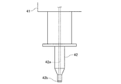
- the suction nozzle 42 is formed in an axial shape as a whole, and an air conduit 42a extending in the axial direction is formed at the center as shown in FIG.
- the air conduit 42a is connected to, for example, a pump that constitutes a suction mechanism of the component mounting head 40, and is supplied with negative pressure. Thereby, the suction nozzle 42 is configured to be able to suck the electronic component at the tip.
- an adhesive sheet 42b capable of varying the adhesive force is disposed at the tip of the suction nozzle 42.
- an ER gel capable of changing the pressure-sensitive adhesive force according to the applied voltage is used in at least a part of the range in contact with the electronic component.
- the adhesive sheet 42b is provided with ER gel over the entire end surface parallel to the XY plane at the tip of the suction nozzle 42. That is, when the suction nozzle 42 holds the electronic component, only the ER gel is in contact with the electronic component.
- an air conduit 42a passes through the central portion of the adhesive sheet 42b.
- the ER gel (Electro-Rheological-Gel) used for the adhesive sheet 42b is a member obtained by gelling ER fluid in which ER particles and an adhesive medium are mixed.
- the ER particles are particles that generate dielectric polarization when an electric field is applied.
- polystyrene particles are used.
- an insulating silicone oil or the like is employed as the adhesive medium. More specifically, as shown in FIG. 4, the adhesive sheet 42b has a one-sided electrode structure in which an electrode 42b2 and an ER gel 42b3 are disposed on the upper surface of the substrate 42b1.
- the adhesive strength of the adhesive sheet 42b is proportional to the magnitude of the voltage applied to the electrode that forms an electric field inside the ER gel. Further, in the adhesive sheet 42b, the surface of the sheet-like ER gel where the substrate and the electrode are arranged is bonded to the main body side of the suction nozzle 42, and the surface opposite to the surface contacts the electronic component. It is a sticky surface to get.
- the pressure-sensitive adhesive sheet 42 b is connected to a power source, and the pressure-sensitive adhesive force to be generated is controlled by adjusting the applied voltage by the mounting control unit 71 of the control device 70.
- the component mounting head 40 has the suction nozzle 42 configured as described above, and its operation is controlled by the control device 70. More specifically, when the mounting control unit 71 of the control device 70 acquires the electronic component supplied to the component supply position Ps of the component supply device 20, first, the suction nozzle 42 is positioned above the component supply position Ps. The component mounting head 40 is moved as described above. Next, the mounting control unit 71 operates the pump of the suction mechanism of the component mounting head 40 and controls so that a predetermined voltage is applied to the adhesive sheet 42b of the suction nozzle 42. Thereby, the suction nozzle 42 is in a state in which a negative pressure is supplied by the pump and an adhesive force corresponding to the applied voltage is generated in the ER gel of the adhesive sheet 42b.
- the mounting control unit 71 lowers the suction nozzle 42 in such a state and brings it into contact with the electronic component at the component supply position Ps. Thereby, the suction nozzle 42 sucks and holds the electronic component.
- the mounting control unit 71 repeatedly performs such a suction operation for the number of suction nozzles 42 supported by the nozzle holder 41. After that, the component mounting head 40 has a plurality of suction nozzles 42 holding electronic components passing above the component camera 50 and passing a predetermined amount above the circuit board B clamped by the transport mechanism 11 of the substrate transport apparatus 10. Move at speed.
- the image processing unit 73 acquires image data obtained by imaging the electronic component in a state where the component camera 50 is held by the suction nozzle 42, and performs predetermined image processing. Thereby, the control device 70 recognizes the holding state of the electronic component by the suction nozzle 42. Then, the mounting control unit 71 calculates a correction amount related to the position and angle of the suction nozzle 42 according to the holding state of the electronic component. The mounting control unit 71 corrects the position and angle of the suction nozzle 42 based on the calculated correction amount, and lowers the suction nozzle 42 to mount the electronic component on the upper surface of the circuit board B.
- the mounting control unit 71 performs control so that the suction nozzle 42 holds the electronic component with a constant holding force while the suction nozzle 42 is lowered to the lowest control end.
- the holding power obtained by combining the suction force and the adhesive force of the suction nozzle 42 is It is controlled to be smaller than the adhesive force based on viscosity.
- the electronic component is detached from the tip of the suction nozzle 42 and bonded to the cream solder, and is mounted on the circuit board B.
- the mounting control unit 71 repeatedly performs such mounting operation for the number of suction nozzles 42 supported by the nozzle holder 41. Further, the mounting control unit 71 performs control so that a predetermined voltage is applied to the ER gel of the adhesive sheet 42b of the suction nozzle 42 when the suction nozzle 42 holds an electronic component. At this time, the mounting control unit 71 of the control device 70 determines the weight of the electronic component, the contact area between the electronic component and the ER gel, and the acceleration applied to the electronic component as the suction nozzle 42 supported by the component transfer device 30 moves. An applied voltage to the ER gel is set based on at least one of them.
- control device 70 can recognize the weight and dimensions of the electronic component held by the suction nozzle 42 based on the control program and component information. Further, the control device 70 can calculate the contact area between the electronic component and the ER gel based on the size and outer shape of the electronic component and the outer shape of the suction nozzle 42 supported by the nozzle holder 41. Furthermore, the control device 70 can calculate the acceleration applied to the electronic component based on the weight of the electronic component and the moving speed of the component mounting head 40. This acceleration includes what is added to the electronic component as the suction nozzle 42 moves up and down.
- the weight, contact area, and acceleration of these electronic components are parameters that affect the holding force necessary for the suction nozzle 42 to hold the electronic component. Therefore, the control device 70 performs control so that the holding force, which is the combined suction force and adhesive force of the suction nozzle 42, is not insufficient by calculating the parameter as described above.
- the mounting control unit 71 of the control device 70 is, for example, an adhesive when the electronic component is heavy and acceleration applied to the electronic component is large, or when the size of the electronic component is small and the contact area with the ER gel is small.
- the voltage applied to the ER gel of the sheet 42b is set higher than usual to control the adhesive force to be increased.
- control device 70 applies the suction force due to the negative pressure supplied to the suction nozzle 42 because the holding force of the suction nozzle 42 is a combination of the suction force and the adhesive force with respect to the voltage applied to the adhesive sheet 42b.
- the adhesive sheet 42b using ER gel is excellent in the responsiveness with respect to an applied voltage, even if an electronic component is hold
- the transport mechanism 11 has a pair of frames 13 disposed on the upper portion of the base frame 12 so as to face each other in the Y-axis direction.
- a guide rail 14 and a conveyor belt 15 extending in the X-axis direction are respectively installed at the upper ends of the pair of frames 13.
- the guide rail 14 includes a guide portion 14a that guides the movement of the circuit board B in the X-axis direction, and a clamp portion 14b that protrudes horizontally in the Y-axis direction so as to be in contact with the upper surface of the circuit board B.
- the conveyor belt 15 is an endless belt suspended on a pulley, and is configured to be circulated by a driving device (not shown).
- the transport mechanism 11 has a lift member 16 disposed between a pair of conveyor belts 15.
- the lift member 16 is configured to be movable in the Z-axis direction by a lifting mechanism (not shown) of the transport mechanism 11. And the lift member 16 contacts the lower surface of the circuit board B carried in by the conveyor belt 15 by raising by the raising / lowering mechanism.
- the lift member 16 is further raised to lift the circuit board B and bring the upper surface of the circuit board B into contact with the lower surface of the clamp portion 14 b of the guide rail 14.
- the lift member 16 is configured to be able to clamp and hold the circuit board B between its upper surface and the clamp portion 14b.
- an adhesive sheet 16 a capable of varying the adhesive force is disposed at the upper end portion of the lift member 16.
- an ER gel capable of varying the adhesive force according to the applied voltage is used in at least a part of the range in contact with the circuit board B.
- the adhesive sheet 16 a is provided with ER gel over the entire end surface parallel to the XY plane at the upper end of the lift member 16. That is, when the lift member 16 is in contact with the circuit board B, only the ER gel is in contact with the circuit board B.
- the adhesive sheet 16a of the lift member 16 has substantially the same configuration as the adhesive sheet 42b of the suction nozzle 42 using ER gel, detailed description thereof is omitted.
- the pressure-sensitive adhesive sheet 16 a of the lift member 16 has an electrode connected to a power source, and the pressure-sensitive adhesive force to be generated is controlled by adjusting the applied voltage by the conveyance control unit 72 of the control device 70.
- the guide rail 14 and the lift member 16 constitute a clamping device for the circuit board B.
- the transport control unit 72 of the control device 70 controls the transport of the circuit board B by the conveyor belt 15 and the operation of the clamping device. More specifically, the conveyance control unit 72 applies a predetermined voltage to the ER gel of the adhesive sheet 16a when the lift member 16 is raised to clamp the circuit board B. And the conveyance control part 72 raises the circuit board B in the state holding the circuit board B with the adhesive force which generate
- the transport control unit 72 applies a predetermined voltage to the ER gel of the adhesive sheet 16a, and holds the circuit board B by the adhesive force generated on the adhesive sheet 16a. And the conveyance control part 72 lowers the lift member 16, and stops the application of the voltage to ER gel, when the lower surface of the circuit board B contacts the conveyor belt 15 again. In this way, when the circuit board B is clamped and unclamped, the transport control unit 72 applies a predetermined voltage to the ER gel to generate an adhesive force on the adhesive sheet 16a, thereby causing the lift member 16 to The circuit board B is prevented from shifting.
- the transport control unit 72 applies a predetermined voltage to the ER gel to generate an adhesive force on the adhesive sheet 16a.
- the transport mechanism 11 is configured to clamp the circuit board B between the clamp portion 14 b and the lift member 16.
- the transport mechanism 11 may be configured such that the guide rail 14 does not have the clamp portion 14 b and holds the circuit board B only by the adhesive force generated on the adhesive sheet 16 a of the lift member 16.
- region ensured in order to contact the lower surface of the clamp part 14b on the upper surface of the circuit board B can be omitted. Therefore, the circuit board B can be reduced in size, or the effective area in which the electronic components can be mounted on the circuit board B can be expanded.
- the suction nozzle 42 as the holding member has the adhesive sheet 42b using ER gel, and when the suction nozzle 42 holds the electronic component, the voltage applied to the ER gel is controlled.
- the configuration is as follows. Thereby, in addition to the suction force by the negative pressure supplied, the suction nozzle 42 can improve a holding force by the part of the adhesive force generated according to the applied voltage to ER gel. Therefore, even if the electronic component to be held is fine, the electronic component can be reliably held. Therefore, this configuration can also be applied to a configuration that speeds up the transfer of electronic components. As a result, it is possible to cope with downsizing of the product and to shorten the cycle time.
- the holding member is a suction nozzle 42 that holds the electronic component by sucking the electronic component by the supplied negative pressure
- the ER gel is arranged at the tip portion that sucks the electronic component.
- the configuration when the electronic component to be mounted on the circuit board B is fine, it is necessary to make the tip of the suction nozzle 42 sucked by the negative pressure thin.
- the suction nozzle 42 needs to secure a contact surface with the electronic component at the tip portion and also ensure a certain cross-sectional area of the air conduit 42a. For this reason, it is not easy to improve the strength of the suction nozzle 42 while securing the necessary suction force.
- the suction nozzle 42 holds the electronic component with the adhesive force of the ER gel in addition to the suction force due to the negative pressure. be able to. Therefore, since the negative pressure required by the suction nozzle 42 can be reduced, the load on the pump of the suction mechanism can be reduced. Furthermore, since the air conduit 42a of the suction nozzle 42 can be set thinner than the conventional one, the degree of freedom in designing the shape of the suction nozzle 42 is improved.
- the control device 70 also determines the ER gel of the adhesive sheet 42b based on at least one of the weight of the electronic component, the contact area between the electronic component and the ER gel, and the acceleration applied to the electronic component as the component transfer device 30 moves.
- the voltage applied to is set. Thereby, the applied voltage to ER gel can be set without excess and deficiency. Therefore, the control device 70 can prevent waste of electric power while generating the necessary adhesive force for the adhesive sheet 42b.
- the assembly machine is the component mounting machine 1 that mounts the electronic component held by the holding member (suction nozzle 42) on the circuit board that is the assembly target under the control of the control device 70.
- the component mounter 1 is markedly refined in circuit board products produced among various assembly machines in the industrial field, and there is a demand for miniaturization of electronic components. Further, assembly machines such as the component mounter 1 are required to shorten the cycle time, and it is necessary to increase the transfer speed of electronic components. Therefore, the component mounter 1 is required to hold the electronic component more reliably. Due to such circumstances, the configuration of the present embodiment can improve the holding force of the holding member by using ER gel, and therefore, the application to the component mounting machine 1 is particularly useful.
- the suction nozzle 42 that is a holding member is formed with an air conduit 42a, and holds the electronic component with a holding force that combines the suction force due to the supplied negative pressure and the adhesive force due to the adhesive sheet 42b. It was.
- the holding member may not have the air conduit 42a, and may hold the electronic component using only the adhesive force of the adhesive sheet 42b formed of ER gel as the holding force.
- the holding member can increase the area where the adhesive sheet 42b contacts the object by the cross-sectional area of the air conduit 42a. Therefore, such a configuration is particularly useful when targeting a fine electronic component.
- chuck device 140 of the second embodiment constitutes a component transfer device in the same manner as the component mounting head 40 of the first embodiment, and is configured to be movable in each axial direction by the operation of the component transfer device. ing.
- the chuck device 140 is a device that holds an electronic component by gripping the electronic component.
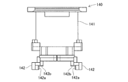
- the chuck device 140 is provided with a pair of gripping claws 142 that face the chuck body 141.
- the chuck body 141 has a drive device that moves the pair of gripping claws 142 in synchronization with the radial direction.
- the pair of gripping claws 142 are detachably fixed to the driving device.
- the chuck device 140 operates the driving device based on a control signal from the control device, and grips an electronic component that is a target object with the pair of gripping claws 142 at a predetermined interval.
- the pair of gripping claws 142 of the chuck device 140 are holding members that hold the electronic component by gripping the electronic component supplied to the component supply position.
- the pair of gripping claws 142 has adhesive sheets 142a and 142b formed of ER gel capable of changing the adhesive force in accordance with the applied voltage at the distal ends thereof. More specifically, the first pressure-sensitive adhesive sheet 142 a is disposed over the entire area of the opposing surfaces of the pair of gripping claws 142.
- the second adhesive sheet 142b is disposed over the entire area of the lower surface of the pair of gripping claws 142 parallel to the XY plane. Therefore, when the chuck device 140 holds the electronic component, only the ER gel of the adhesive sheets 142a and 142b is in contact with the electronic component.
- the adhesive sheets 142a and 142b of the pair of gripping claws 142 have substantially the same configuration as the adhesive sheet 42b of the suction nozzle 42 in which the ER gel is used in the first embodiment, and thus detailed description thereof is omitted.
- the adhesive sheets 142 a and 142 b of the pair of gripping claws 142 have electrodes connected to a power source, and the generated adhesive force is controlled by adjusting the applied voltage by the mounting control unit 71 of the control device 70.
- the chuck device 140 holds the target electronic component by a holding force that combines the gripping force applied by the pair of gripping claws 142 and the adhesive force generated in the adhesive sheets 142a and 142b.
- the control of acquisition and transfer of electronic components by the chuck device 140 is the same as the control for the component mounting head 40 of the first embodiment, and thus detailed description thereof is omitted.
- the period during which the voltage is applied to the adhesive sheets 142a and 142b of the chuck device 140 is preferably within the period during which the gripping claws 142 are gripping the object. This is because when the adhesive sheets 142a and 142b to which a voltage is applied come into contact with the object, the frictional force between the gripping claws 142 and the object increases, which affects the posture when the object is gripped or placed. Because it does.
- the holding member is a gripping claw 142 constituting the chuck device 140 that holds an electronic component by gripping the electronic component.
- the chuck device 140 can hold the electronic component with the adhesive force of the ER gel of the adhesive sheets 142a and 142b.
- the chuck device 140 gripped by a plurality of gripping claws also prevents the tip of the gripping claws 142 from being interfered with other components. It is necessary to make it thinner. Further, in consideration of the case where the maximum value of the gripping force is regulated by the load resistance of the electronic component, it is necessary to control the gripping force with high accuracy. On the other hand, since the holding power can be improved by the amount of the adhesive force generated in the adhesive sheets 142a and 142b by adopting the configuration as in the present embodiment, the electronic component can be reliably held. Further, since the ER gel has elasticity, the adhesive sheets 142a and 142b can be used as buffer members.
- the component mounter recognizes the holding state of the electronic component based on image data captured by the component camera, and corrects the position and angle of the suction nozzle according to the holding state, thereby improving the mounting control accuracy. Yes. For such mounting control, it is necessary to inspect whether or not the position and angle of the actually mounted electronic component are properly corrected. That is, the component mounter performs an accuracy check of mounting control for transferring the electronic component held by the suction nozzle to the mounting position, and calibrates the correction amount calculated by the control device.
- Japanese Patent Application Laid-Open No. 2001-136000 discloses a method for inspecting the accuracy of mounting control using an inspection jig (inspection board) provided with a plurality of reference marks.
- the control device first places a pseudo part for inspection on the inspection jig corresponding to the reference mark.
- the control device captures an image of the inspection jig on which the pseudo component is placed with the board camera.
- the control device detects the position of the pseudo component with respect to each reference mark based on the image data obtained by imaging, and determines whether or not the correction is appropriately performed.
- a double-sided pressure-sensitive adhesive sheet is attached to the upper surface of an inspection jig used for accuracy inspection of mounting control, for example, in order to hold the placed electronic component. That is, in actual mounting control, an electronic component is mounted on a cream solder having an adhesive force, and a holding member such as a double-sided adhesive sheet is used instead of the cream solder.
- a double-sided pressure-sensitive adhesive sheet gradually needs to be replaced at every accuracy inspection because the adhesive force gradually decreases.
- an object is to provide an inspection jig that can reliably hold a target part and facilitate the removal of the part, thereby improving the convenience in the accuracy inspection of the assembly machine.
- the assembly machine in the present embodiment is a component mounter, and the configuration of the component mounter is substantially the same as that of the first embodiment, and thus detailed description thereof is omitted.
- the inspection jig is clamped by the transport mechanism of the substrate transport apparatus and fixed at a predetermined position.
- the inspection jig 280 is used for accuracy inspection of assembly control (mounting control) for transferring an electronic component held by the suction nozzle 42 as a holding member to an assembly position (mounting position).
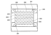
- the inspection jig 280 is mounted with an electronic component or a pseudo component for inspection instead of the circuit board B which is an assembly target in the accuracy inspection. More specifically, the inspection jig 280 is formed in the same outer shape as the circuit board B. As shown in FIG. 7, two inspection marks 281 and a plurality of reference marks 282 are arranged in parallel to each other. Adhesive sheet 283.
- the substrate mark 281 is a fiducial mark serving as a reference for detecting the position of the inspection jig 280 and is arranged at two corners on the diagonal line of the inspection jig 280.
- the reference mark 282 is a fiducial mark that serves as a reference when placing an electronic component or a pseudo component for inspection, and is regularly arranged on the upper surface of the inspection jig 280 with a predetermined interval. .
- the pressure-sensitive adhesive sheet 283 has a tape shape and is disposed at a mounting position where an electronic component or a pseudo component is placed in an accuracy inspection.
- an ER gel 283a whose adhesive force can be changed according to the applied voltage is used on the upper surface of the substrate. Therefore, in a state where the electronic component or the pseudo component is placed on the inspection jig 280, the ER gel 283a is in contact with the electronic component or the pseudo component.
- the adhesive sheet 283 of the inspection jig 280 has substantially the same configuration as the adhesive sheet 42b of the suction nozzle 42 using the ER gel in the first embodiment, and thus detailed description thereof is omitted. Further, the adhesive sheet 283 has an electrode connected to a power source, and the adhesive force to be generated is controlled by adjusting the applied voltage by operating the control device 70 or a dial (not shown). With such a configuration, the inspection jig 280 holds the target electronic component or pseudo component by the adhesive force generated in the adhesive sheet 283 in the accuracy inspection.
- the holding state of the electronic component can be released by releasing the application of the voltage to the adhesive sheet. Therefore, it is possible to easily collect the electronic parts used for the accuracy inspection. Therefore, with the configuration as in the present embodiment, the convenience of the inspection jig in the accuracy inspection of the component mounter can be improved.
- the assembly machine constitutes the component mounting machine 1
- the assembly control can be performed based on the measured three-dimensional shape of the part.
- the assembly machine may constitute a manufacturing facility for assembling a power module or the like, for example. Even in such a configuration, the same effect as the present embodiment can be obtained.
Landscapes
- Engineering & Computer Science (AREA)
- Manufacturing & Machinery (AREA)
- Microelectronics & Electronic Packaging (AREA)
- Supply And Installment Of Electrical Components (AREA)
- Manipulator (AREA)
Abstract
対象部品を確実に保持することによって、製品の小型化やサイクルタイムの短縮に対応できる組立機、当該組立機に用いられる保持部材および検査治具を提供することを目的とする。 組立機は、部品と接触する範囲の少なくとも一部に印加電圧に応じて粘着力を変動可能なERゲルが用いられている保持部材と、保持部材に保持された部品を位置決めされた被組立体における組立位置まで移載可能に保持部材を支持する移載装置と、保持部材の昇降および移載装置の移動を制御するとともに、保持部材が部品を保持する際にERゲルへの印加電圧を制御する制御装置とを備える。
Description
本発明は、部品を供給位置から組立位置まで移載して部品を被組立体に組み付ける組立機と、当該組立機に用いられる保持部材および検査治具に関するものである。
組立機は、回路基板に複数の電子部品を実装して電子回路製品を生産する部品実装機や、パワーモジュールなどを組み立てる製造設備として用いられる。このような部品実装機として、特許文献1には、保持部材である吸着ノズルに負圧を供給することによって、部品供給位置にある電子部品を吸着して、この電子部品を部品組立位置(回路基板上の所定の座標位置)に実装する構成が開示されている。また、特許文献2には、チャック装置を保持部材として、当該チャック装置の複数の把持爪により電子部品を把持する構成が開示されている。
ところで、部品実装機などの組立機においては、製品の小型化などに伴って、微細な部品が対象となることがある。また、製品の組み立てに要する時間を短縮するために、部品を保持した状態にある保持部材の移動速度をより高速に設定することがある。そのため、組立機における保持部材には、対象部品の確実な保持が求められる。また、組立機における検査治具には、組立制御の精度検査において、対象部品が微細であっても当該部品の確実な保持が求められる。
本発明は、このような事情に鑑みてなされたものであり、対象部品を確実に保持することによって、製品の小型化やサイクルタイムの短縮に対応できる組立機、当該組立機に用いられる保持部材および検査治具を提供することを目的とする。
請求項1に係る組立機は、供給位置に供給された部品を取得して保持する保持部材であって、前記部品と接触する範囲の少なくとも一部に印加電圧に応じて粘着力を変動可能なERゲルが用いられている前記保持部材と、前記保持部材に保持された前記部品を位置決めされた被組立体における組立位置まで移載可能に前記保持部材を支持する移載装置と、前記保持部材の昇降および前記移載装置の移動を制御するとともに、前記保持部材が前記部品を保持する際に前記ERゲルへの印加電圧を制御する制御装置と、を備える。
このような構成によると、保持部材は、部品を保持する際にERゲルに電圧が適宜印加され、部品を保持可能な状態となる。そして、保持部材は、電圧を印加されたERゲルが保持対象とする部品と接触することにより、印加電圧に応じた粘着力の分だけ保持力を向上できる。よって、対象部品が微細であっても確実に部品を保持することが可能となり、また移動速度の高速化にも適応できる。従って、製品の小型化に対応し、またサイクルタイムを短縮することができる。
請求項7に係る保持部材は、供給位置で取得した部品を組立位置に移載して当該部品を被組立体に組み付ける組立機に用いられ、前記供給位置に供給された前記部品を取得して保持する保持部材であって、前記部品と接触する範囲の少なくとも一部に印加電圧に応じて粘着力を変動可能なERゲルが用いられている。
このような構成によると、保持部材は、部品を保持する際に、電圧を印加されたERゲルが部品と接触することにより、印加電圧に応じた粘着力の分だけ保持力を向上できる。よって、対象部品が微細であっても確実に部品を保持することが可能となり、また移動速度の高速化にも対応できる。従って、製品の小型化やサイクルタイムの短縮の要請がある組立機への保持部材の適用は、特に有用である。
請求項10に係る検査治具は、供給位置で取得した部品を組立位置に移載して、当該部品を被組立体に組み付ける組立機において、保持された前記部品を前記組立位置に移載する組立制御の精度検査に用いられ、前記精度検査において前記被組立体に換えて前記部品または検査用の疑似部品を載置される検査治具であって、前記部品または前記疑似部品を載置される前記組立位置に、印加電圧に応じて粘着力を変動可能なERゲルにより形成された粘着シートを有する。
このような構成によると、検査治具は、部品または疑似部品を保持する際に、電圧を印加された粘着シートが部品と接触することにより、印加電圧に応じた粘着力によって載置された部品を保持できる。よって、対象部品が微細であっても確実に部品を保持することができる。また、精度検査が終了した際には、粘着シートへの電圧の印加を解除することによって、部品または疑似部品の保持状態を解除することができる。よって、精度検査に用いられた部品等の回収を簡易にすることができる。従って、製品の小型化の要請がある組立機への検査治具の適用は、特に有用である。
以下、本発明の組立機、当該組立機に用いられる保持部材および検査治具を具体化した実施形態について図面を参照して説明する。本実施形態において、組立機は、回路基板(被組立体)に電子部品を実装して生産される回路基板製品を対象とする部品実装機である構成を例示する。部品実装機は、例えば集積回路の製造工程において、回路基板上に複数の電子部品を装着する装置である。この回路基板は、例えばスクリーン印刷機により電子部品の装着位置(組立位置)にクリームハンダが塗布され、複数の部品実装機を順に搬送されて電子部品が装着される。その後に、電子部品が装着された回路基板は、リフロー炉に搬送されてハンダ付けされることにより回路基板製品として集積回路を構成する。
<第一実施形態>
(部品実装機の全体構成)
部品実装機1の全体構成について、図1,2を参照して説明する。部品実装機1は、基板搬送装置10と、部品供給装置20と、部品移載装置30と、部品カメラ50と、基板カメラ60と、制御装置70とを備えて構成される。各装置10,20,30および各カメラ50,60は、部品実装機1の基台2に設けられ、制御装置70により制御される。また、図1に示すように、部品実装機1の水平幅方向(図1の左上から右下に向かう方向)をX軸方向、部品実装機1の水平長手方向(図1の右上から左下に向かう方向)をY軸方向、鉛直高さ方向(図1の上下方向)をZ軸方向とする。
(部品実装機の全体構成)
部品実装機1の全体構成について、図1,2を参照して説明する。部品実装機1は、基板搬送装置10と、部品供給装置20と、部品移載装置30と、部品カメラ50と、基板カメラ60と、制御装置70とを備えて構成される。各装置10,20,30および各カメラ50,60は、部品実装機1の基台2に設けられ、制御装置70により制御される。また、図1に示すように、部品実装機1の水平幅方向(図1の左上から右下に向かう方向)をX軸方向、部品実装機1の水平長手方向(図1の右上から左下に向かう方向)をY軸方向、鉛直高さ方向(図1の上下方向)をZ軸方向とする。
基板搬送装置10は、回路基板BをX軸方向に搬送するとともに、回路基板Bを所定位置に位置決めする。この基板搬送装置10は、Y軸方向に並設された複数の搬送機構11により構成されたダブルコンベアタイプである。搬送機構11は、電子部品の装着処理に際して、コンベアベルトにより回路基板Bを所定のX軸方向位置まで搬入して、クランプ装置により回路基板Bをクランプする。そして、搬送機構11は、回路基板Bに電子部品が装着されると、回路基板Bをアンクランプして、部品実装機1の機外に回路基板Bを搬出する。
また、搬送機構11は、本実施形態において、上記のクランプ装置における回路基板Bと接触する範囲の少なくとも一部にERゲルが用いられている。つまり、クランプ装置は、回路基板Bを位置決めする際に、本来のクランプ力に加えて、ERゲルへの印加電圧に応じて変動するERゲルの粘着力をもって回路基板Bを保持する構成としている。この搬送機構11のクランプ装置の詳細な構成については後述する。
部品供給装置20は、回路基板Bに実装される電子部品を供給する装置である。部品供給装置20は、部品実装機1のY軸方向の前部側(図1の左下側)に配置されている。この部品供給装置20は、本実施形態において、複数のカセット式のフィーダ21を用いたフィーダ方式としている。フィーダ21は、基台2に対して着脱可能に取り付けられるフィーダ本体部21aとフィーダ本体部21aの後端側に設けられたリール収容部21bとを有する。フィーダ21は、リール収容部21bにより部品包装テープが巻回された供給リール22を保持している。
上記の部品包装テープは、電子部品が所定ピッチで収納されたキャリアテープと、このキャリアテープの上面に接着されて電子部品を覆うトップテープとにより構成される。フィーダ21は、図示しないピッチ送り機構により供給リール22から引き出された部品包装テープをピッチ送りする。そして、フィーダ21は、キャリアテープからトップテープを剥離して電子部品を露出させている。これにより、フィーダ21は、フィーダ本体部21aの前端側に位置する部品供給位置Psにおいて、部品移載装置30の吸着ノズル42が電子部品を吸着可能となるように電子部品の供給を行っている。
部品移載装置30は、電子部品を部品供給位置Psから回路基板Bの実装位置に移載する装置である。本実施形態において、部品移載装置30は、基板搬送装置10および部品供給装置20の上方に配置された直交座標型としている。この部品移載装置30は、Y軸方向に延在する一対のY軸レール31にY軸方向に移動可能にY軸移動台32が設けられている。Y軸移動台32は、ボールねじ機構を介してY軸モータ33の動作により制御される。また、Y軸移動台32には、X軸移動台34がX軸方向に移動可能に設けられている。X軸移動台34は、図示しないボールねじ機構を介してX軸モータ35の動作により制御される。
また、X軸移動台34には、部品装着ヘッド40が取り付けられている。この部品装着ヘッド40は、Z軸と平行なR軸回りに回転可能なノズルホルダ41により複数の吸着ノズル42を昇降可能に支持する。部品装着ヘッド40は、フレーム43を介してX軸移動台34に固定されている。また、ノズルホルダ41は、R軸モータ44の出力軸に連結され、R軸モータ44によって回転制御可能に構成されている。吸着ノズル42は、Z軸モータ45などにより構成される昇降機構によりZ軸方向の移動を制御されるとともに、図示しないθ軸モータの回転駆動により自転角度を制御される。
また、吸着ノズル42は、部品装着ヘッド40における吸着機構を構成し、供給される負圧によって電子部品を吸着可能としている。さらに、吸着ノズル42は、本実施形態において、吸着ノズル42の先端部における電子部品と接触する範囲の少なくとも一部にERゲルが用いられている。つまり、吸着ノズル42は、電子部品を保持する際に、本来の負圧による吸着力に加えて、ERゲルへの印加電圧に応じて変動するERゲルの粘着力をもって電子部品を保持する構成としている。この吸着ノズル42の詳細な構成については後述する。
部品カメラ50および基板カメラ60は、CCD(Charge Coupled Device)やCMOS(Complementary Metal Oxide Semiconductor)等の撮像素子を有するデジタル式の撮像装置である。部品カメラ50および基板カメラ60は、通信可能に接続された制御装置70による制御信号に基づいてカメラ視野に収まる範囲の撮像を行い、当該撮像により取得した画像データを制御装置70に送出する。
部品カメラ50は、光軸がZ軸方向となるように基台2に固定され、吸着ノズル42に保持された状態の電子部品を撮像可能に構成されている。この部品カメラ50から画像データを取得した制御装置70は、画像処理により吸着ノズル42による電子部品の保持状態を認識する。このように、電子部品の保持状態に応じて吸着ノズル42の位置および角度を補正することで、実装制御の精度向上を図ることが可能となる。
基板カメラ60は、光軸がZ軸方向となるようにX軸移動台34に固定され、回路基板Bを撮像可能に構成されている。この基板カメラ60から画像データを取得した制御装置70は、画像処理により例えば基板に付された基板マークを認識することで、基板搬送装置10による回路基板Bの位置決め状態を認識する。そして、制御装置70は、回路基板Bの位置決め状態に応じてY軸移動台32およびX軸移動台34を位置補正して、電子部品の装着を行うように制御する。このように、基板カメラ60の撮像による画像データを用いることにより、実装制御の精度向上を図ることが可能となる。
制御装置70は、主として、CPUや各種メモリ、制御回路により構成され、部品カメラ50および基板カメラ60の撮像により取得した画像データに基づいて回路基板Bへの電子部品の実装を制御する。この制御装置70は、図2に示すように、実装制御部71、搬送制御部72、画像処理部73、および記憶部74に、バスを介して入出力インターフェース75が接続されている。入出力インターフェース75には、モータ制御回路76および撮像制御回路77が接続されている。
実装制御部71は、モータ制御回路76を介して部品装着ヘッド40の位置や吸着機構の動作を制御する。より詳細には、実装制御部71は、部品実装機1に複数設けられた各種センサから出力される情報や、各種の認識処理の結果を入力する。そして、実装制御部71は、記憶部74に記憶されている制御プログラム、各種センサによる情報、画像処理や認識処理の結果に基づいて、モータ制御回路76に制御信号を送出する。これにより、部品装着ヘッド40に支持された吸着ノズル42の位置および回転角度が制御される。また、実装制御部71は、部品装着ヘッド40の吸着機構のポンプによる吸着ノズル42への負圧の供給、および吸着ノズル42のERゲルへの印加電圧を調整することにより、吸着ノズル42による電子部品の保持状態を制御する。
搬送制御部72は、基板搬送装置10による回路基板Bの搬送およびクランプ装置の動作を制御する。また、搬送制御部72は、クランプ装置が回路基板Bをクランプおよびアンクランプする際に、クランプ装置に設けられたERゲルへの印加電圧を調整することにより、クランプ装置による回路基板Bの保持状態を制御する。画像処理部73は、撮像制御回路77を介して部品カメラ50および基板カメラ60の撮像による画像データを取得して、用途に応じた画像処理を実行する。この画像処理には、例えば、画像データの二値化、フィルタリング、色相抽出などの加工処理などが含まれる。
記憶部74は、ハードディスク装置などの光学ドライブ装置、またはフラッシュメモリなどにより構成される。この記憶部74には、部品実装機1を動作させるための制御プログラム、バスや通信ケーブルを介して部品カメラ50および基板カメラ60から制御装置70に転送された画像データ、画像処理部73による処理の一時データなどが記憶される。入出力インターフェース75は、CPUや記憶部74と各制御回路76,77との間に介在し、データ形式の変換や信号強度を調整する。
モータ制御回路76は、実装制御部71による制御信号に基づいて、Y軸モータ33、X軸モータ35、R軸モータ44、Z軸モータ45、およびθ軸モータを制御する。これにより、部品装着ヘッド40が各軸方向に位置決めされるとともに、吸着ノズル42が所定角度となるように制御される。撮像制御回路77は、制御装置70のCPUなどによる撮像の制御信号に基づいて、部品カメラ50および基板カメラ60による撮像を制御する。また、撮像制御回路77は、部品カメラ50および基板カメラ60の撮像による画像データを取得して、入出力インターフェース75を介して記憶部74に記憶させる。
(吸着ノズルの詳細構成)
吸着ノズル42の詳細構成について、図3および図4を参照して説明する。吸着ノズル42は、部品供給装置20により部品供給位置Psに供給された電子部品を取得して保持する保持部材である。吸着ノズル42は、全体形状としては軸状に形成され、図3に示すように、中心部に軸方向に延びる空気導管42aが形成されている。空気導管42aは、例えば部品装着ヘッド40の吸着機構を構成するポンプに連結され、負圧を供給される。これにより、吸着ノズル42は、その先端部において電子部品を吸着可能に構成されている。
吸着ノズル42の詳細構成について、図3および図4を参照して説明する。吸着ノズル42は、部品供給装置20により部品供給位置Psに供給された電子部品を取得して保持する保持部材である。吸着ノズル42は、全体形状としては軸状に形成され、図3に示すように、中心部に軸方向に延びる空気導管42aが形成されている。空気導管42aは、例えば部品装着ヘッド40の吸着機構を構成するポンプに連結され、負圧を供給される。これにより、吸着ノズル42は、その先端部において電子部品を吸着可能に構成されている。
また、吸着ノズル42の先端部には、粘着力を変動可能な粘着シート42bが配置されている。この粘着シート42bは、電子部品と接触する範囲の少なくとも一部に印加電圧に応じて粘着力を変動可能なERゲルが用いられている。本実施形態においては、粘着シート42bは、吸着ノズル42の先端部におけるXY平面に平行な端面の全域に亘ってERゲルを配置されている。つまり、吸着ノズル42が電子部品を保持した状態においては、ERゲルのみが電子部品に接触する構成となっている。また、粘着シート42bの中心部には、空気導管42aが貫通している。
ここで、粘着シート42bに用いられているERゲル(Electro Rheological Gel)は、ER粒子と粘着性媒体を混合したER流体をゲル化した部材である。ER粒子は、電界を印加させると誘電分極を生じる粒子であって、例えばポリスチレン粒子などが採用される。粘着性媒体は、絶縁性を有するシリコーンオイルなどが採用される。より詳細には、粘着シート42bは、図4に示すように、基板42b1の上面に電極42b2とERゲル42b3とが配置された片側電極構造となっている。
このような構成により、電極42b2に所定の電圧が印加されると、図4の矢印で示すように電気力線がERゲル42b3を通過する。そうすると、ERゲル42b3のER粒子は、印加電圧に応じてゲル化された粘着性媒体の内部へ沈み込む。結果として、ERゲル42b3の表面に現れているゲル部分の割合が増加して、粘着シート42bの粘着性が生じることになる。一方で、電極42b2への電圧の印加を停止してERゲル42b3から電界を除去すると、ER粒子がERゲル42b3の表面から突出する。これにより、粘着シート42bの粘着性が失われる。
上記のように、粘着シート42bの粘着力は、ERゲルの内部に電界を形成する電極への印加電圧の大きさに比例する。また、粘着シート42bにおいて、シート状のERゲルの表面のうち、基板および電極が配置された面が吸着ノズル42の本体側に接着され、当該面とは反対側の面が電子部品と接触し得る粘着面である。粘着シート42bは、電極を電源に接続され、制御装置70の実装制御部71による印加電圧の調整をもって、発生させる粘着力を制御される。
部品装着ヘッド40は、上記のような構成からなる吸着ノズル42を有し、制御装置70により動作を制御される。より詳細には、制御装置70の実装制御部71は、部品供給装置20の部品供給位置Psに供給された電子部品を取得する際に、先ず、吸着ノズル42が部品供給位置Psの上方に位置するように部品装着ヘッド40を移動させる。次に、実装制御部71は、部品装着ヘッド40の吸着機構のポンプを動作させるとともに、吸着ノズル42の粘着シート42bに所定の電圧が印加されるように制御する。これにより、吸着ノズル42は、ポンプにより負圧が供給されるとともに、粘着シート42bのERゲルに印加電圧に応じた粘着力が生じた状態となる。
実装制御部71は、このような状態にある吸着ノズル42を下降させて、部品供給位置Psにある電子部品に接触させる。これにより、吸着ノズル42は、電子部品を吸着して保持する。実装制御部71は、このような吸着動作をノズルホルダ41が支持する吸着ノズル42の数量だけ繰り返し実行する。その後に、部品装着ヘッド40は、電子部品を保持した複数の吸着ノズル42が部品カメラ50の上方を経由しながら、基板搬送装置10の搬送機構11によりクランプされた回路基板Bの上方に所定の速度で移動する。
画像処理部73は、部品カメラ50が吸着ノズル42に保持された状態の電子部品を対象とした撮像による画像データを取得して、所定の画像処理を行う。これにより、制御装置70は、吸着ノズル42による電子部品の保持状態を認識する。そして、実装制御部71は、電子部品の保持状態に応じて吸着ノズル42の位置および角度に係る補正量を算出する。実装制御部71は、算出された補正量に基づいて吸着ノズル42の位置および角度を補正するとともに、吸着ノズル42を下降させて電子部品を回路基板Bの上面に装着させる。
このとき、実装制御部71は、吸着ノズル42が制御上の最下端まで下降する間は、吸着ノズル42が一定の保持力により電子部品を保持するように制御する。その後に、吸着ノズル42の吸着力および粘着力を合わせた保持力は、吸着ノズル42により保持された電子部品が回路基板Bの上面に塗布されたクリームハンダに接触した際に、当該クリームハンダの粘性に基づく接着力よりも小さくなるように制御される。これにより、電子部品は、吸着ノズル42の先端部から離脱するとともにクリームハンダに接着されて、回路基板Bに装着される。
実装制御部71は、このような装着動作をノズルホルダ41が支持する吸着ノズル42の数量だけ繰り返し実行する。また、実装制御部71は、吸着ノズル42が電子部品を保持する際に、吸着ノズル42の粘着シート42bのERゲルに所定電圧を印加するように制御する。このとき、制御装置70の実装制御部71は、電子部品の重量、電子部品とERゲルの接触面積、部品移載装置30に支持された吸着ノズル42の移動に伴い電子部品に加えられる加速度のうち少なくとも一つに基づいて、ERゲルへの印加電圧を設定する。
より詳細には、制御装置70は、制御プログラムや部品情報に基づいて、吸着ノズル42が保持している電子部品の重量や寸法を認識できる。また、制御装置70は、電子部品の寸法や外形、およびノズルホルダ41に支持されている吸着ノズル42の外形に基づいて、電子部品とERゲルの接触面積を算出できる。さらに、制御装置70は、電子部品の重量、および部品装着ヘッド40の移動速度に基づいて、電子部品に加えられる加速度を算出できる。この加速度には、吸着ノズル42の昇降に伴って電子部品に加えられるものを含む。
これらの電子部品の重量や接触面積、加速度は、吸着ノズル42が電子部品を保持するために必要な保持力に影響するパラメータである。そこで、制御装置70は、当該パラメータを上記のように算出することによって、吸着ノズル42の吸着力および粘着力を合わせた保持力が不足しないように制御する。具体的には、制御装置70の実装制御部71は、例えば電子部品が重く、電子部品に加わる加速度が大きい場合や、電子部品の寸法が小さくERゲルとの接触面積が小さい場合には、粘着シート42bのERゲルに印加する電圧を通常よりも高く設定して、粘着力を増加させるように制御する。
また、制御装置70は、粘着シート42bへの印加電圧については、吸着ノズル42の保持力が吸着力と粘着力を合わせたものであることから、吸着ノズル42に供給される負圧による吸着力に基づいて設定するようにしてもよい。つまり、保持対象の電子部品によっては、吸着に向かない表面形状をなしている場合には、粘着シート42bによる保持力の割合を高くする。これにより、吸着機構のポンプの負荷を軽減することが可能となる。また、ERゲルを用いた粘着シート42bは、印加電圧に対する応答性に優れていることから、例えば電子部品の取得時や装着時において、粘着シート42bの粘着力のみで電子部品を保持してもよい。
(搬送機構の詳細構成)
基板搬送装置10の搬送機構11の詳細構成について、図4および図5を参照して説明する。搬送機構11は、基枠12の上部にY軸方向に対向して配置された一対のフレーム13を有する。一対のフレーム13の上端部には、X軸方向に延びるガイドレール14およびコンベアベルト15がそれぞれ設置されている。ガイドレール14は、回路基板BのX軸方向の移動を案内するガイド部14aと、回路基板Bの上面と接触可能となるようにY軸方向に水平に突出したクランプ部14bとを有する。コンベアベルト15は、プーリに懸架された無端ベルトであって、図示しない駆動装置により循環可能に構成されている。
基板搬送装置10の搬送機構11の詳細構成について、図4および図5を参照して説明する。搬送機構11は、基枠12の上部にY軸方向に対向して配置された一対のフレーム13を有する。一対のフレーム13の上端部には、X軸方向に延びるガイドレール14およびコンベアベルト15がそれぞれ設置されている。ガイドレール14は、回路基板BのX軸方向の移動を案内するガイド部14aと、回路基板Bの上面と接触可能となるようにY軸方向に水平に突出したクランプ部14bとを有する。コンベアベルト15は、プーリに懸架された無端ベルトであって、図示しない駆動装置により循環可能に構成されている。
また、搬送機構11は、一対のコンベアベルト15の間に配置されたリフト部材16を有する。リフト部材16は、搬送機構11の図示しない昇降機構によって、Z軸方向に移動可能に構成されている。そして、リフト部材16は、昇降機構により上昇することによって、コンベアベルト15によって搬入された回路基板Bの下面に接触する。リフト部材16は、さらに上昇することによって、回路基板Bを持ち上げて、回路基板Bの上面をガイドレール14のクランプ部14bの下面に接触させる。このように、リフト部材16は、その上面とクランプ部14bとの間で回路基板Bをクランプして保持可能に構成されている。
また、リフト部材16の上端部には、粘着力を変動可能な粘着シート16aが配置されている。この粘着シート16aは、回路基板Bと接触する範囲の少なくとも一部に印加電圧に応じて粘着力を変動可能なERゲルが用いられている。本実施形態においては、粘着シート16aは、リフト部材16の上端部におけるXY平面に平行な端面の全域に亘ってERゲルを配置されている。つまり、リフト部材16が回路基板Bと接触した状態においては、ERゲルのみが回路基板Bに接触する構成となっている。ここで、リフト部材16の粘着シート16aは、ERゲルが用いられた吸着ノズル42の粘着シート42bと実質的に同一の構成であるため詳細な説明を省略する。また、リフト部材16の粘着シート16aは、電極を電源に接続され、制御装置70の搬送制御部72による印加電圧の調整をもって、発生させる粘着力を制御される。
上記のように、ガイドレール14およびリフト部材16は、回路基板Bを対象としたクランプ装置を構成している。このような構成からなる搬送機構11は、制御装置70の搬送制御部72により、コンベアベルト15による回路基板Bの搬送、およびクランプ装置の動作を制御される。より詳細には、搬送制御部72は、回路基板Bをクランプするためにリフト部材16を上昇させる際に、粘着シート16aのERゲルに所定の電圧を印加する。そして、搬送制御部72は、粘着シート16aに発生した粘着力により回路基板Bを保持させた状態で回路基板Bを上昇させて、クランプ部14bとの間で回路基板Bをクランプする。
また、搬送制御部72は、回路基板Bをアンクランプする際に、粘着シート16aのERゲルに所定の電圧を印加し、粘着シート16aに発生した粘着力により回路基板Bを保持させる。そして、搬送制御部72は、リフト部材16を下降させて、回路基板Bの下面が再びコンベアベルト15に接触する際に、ERゲルへの電圧の印加を停止する。このように、搬送制御部72は、回路基板Bのクランプおよびアンクランプする際に、ERゲルに所定の電圧を印加して粘着シート16aに粘着力を発生させることで、リフト部材16に対して回路基板Bがずれることを防止している。
その他に、搬送制御部72は、クランプ部14bとリフト部材16との間で回路基板Bをクランプしている状態において、ERゲルに所定の電圧を印加して粘着シート16aに粘着力を発生させるように制御してもよい。このような構成によると、搬送機構11は、リフト部材16の上昇力によるクランプ力に加えて、粘着シート16aの粘着力をもって回路基板Bを保持することができる。よって、搬送機構11は、粘着シート16aの粘着力を適宜調整されることによって、回路基板Bに過剰なクランプ力を加えることなく回路基板Bをより確実に固定することができる。
また、本実施形態では、搬送機構11は、クランプ部14bとリフト部材16との間で回路基板Bをクランプする構成とした。これに対して、搬送機構11は、ガイドレール14がクランプ部14bを有さず、リフト部材16の粘着シート16aに発生した粘着力のみによって回路基板Bを保持する構成としてもよい。これにより、回路基板Bの上面にはクランプ部14bの下面と接触するために確保していた領域を省くことができる。よって、回路基板Bを小型化したり、或いは回路基板Bにおいて電子部品を実装可能な有効領域を拡大したりすることが可能となる。
(本実施形態の構成による効果)
上述した部品実装機1によると、保持部材である吸着ノズル42がERゲルを用いられた粘着シート42bを有し、吸着ノズル42が電子部品を保持する際に、ERゲルへの印加電圧が制御される構成とした。これにより、吸着ノズル42は、供給される負圧による吸着力に加えて、ERゲルへの印加電圧に応じて発生する粘着力の分だけ保持力を向上できる。よって、保持対象の電子部品が微細であっても、電子部品を確実に保持することが可能となる。従って、本構成は、電子部品の移載を高速化する構成にも適応できる。結果として、製品の小型化に対応し、またサイクルタイムを短縮することができる。
上述した部品実装機1によると、保持部材である吸着ノズル42がERゲルを用いられた粘着シート42bを有し、吸着ノズル42が電子部品を保持する際に、ERゲルへの印加電圧が制御される構成とした。これにより、吸着ノズル42は、供給される負圧による吸着力に加えて、ERゲルへの印加電圧に応じて発生する粘着力の分だけ保持力を向上できる。よって、保持対象の電子部品が微細であっても、電子部品を確実に保持することが可能となる。従って、本構成は、電子部品の移載を高速化する構成にも適応できる。結果として、製品の小型化に対応し、またサイクルタイムを短縮することができる。
また、本実施形態において、保持部材は、供給される負圧により電子部品を吸着して電子部品を保持する吸着ノズル42であって、電子部品を吸着する先端部にERゲルが配置されている構成とした。ここで、回路基板Bに装着する電子部品が微細な場合には、負圧によって吸着する吸着ノズル42は、その先端部を細くする必要がある。一方で、吸着ノズル42は、電子部品を保持するために、その先端部に電子部品との接触面を確保しつつ、空気導管42aもある程度の断面積を確保する必要がある。そのため、吸着ノズル42が必要な吸着力を確保しつつ、吸着ノズル42の強度を向上することは容易ではない。
これに対して、吸着ノズル42がERゲルを用いた粘着シート42bを有する構成とすることで、吸着ノズル42は、負圧による吸着力に加えて、ERゲルの粘着力をもって電子部品を保持することができる。よって、吸着ノズル42が必要とする負圧を低減することができるので、吸着機構のポンプの負荷を軽減できる。さらに、吸着ノズル42の空気導管42aを従来よりも細く設定することが可能となるので、吸着ノズル42の形状の設計自由度が向上する。
また、制御装置70は、電子部品の重量、電子部品とERゲルの接触面積、部品移載装置30の移動に伴い電子部品に加えられる加速度の少なくとも一つに基づいて、粘着シート42bのERゲルへの印加電圧を設定する構成とした。これにより、ERゲルへの印加電圧を過不足なく設定することができる。よって、制御装置70は、粘着シート42bに必要な粘着力を発生させつつ、電力の浪費を防ぐことができる。
本実施形態において、組立機は、制御装置70の制御により被組立体である回路基板に保持部材(吸着ノズル42)が保持する電子部品を実装する部品実装機1であるものとした。部品実装機1は、工業分野における種々の組立機の中でも生産する回路基板製品の精密化が顕著であり、電子部品の微細化の要請がある。また、部品実装機1などの組立機には、サイクルタイムの短縮が求められ、電子部品の移載の高速化が必要とされる。そのため、部品実装機1においては、電子部品をより確実に保持することが求められる。このような事情により、本実施形態の構成は、ERゲルを用いることにより保持部材の保持力を向上できることから、部品実装機1への適用が特に有用である。
<第一実施形態の変形態様>
本実施形態において、保持部材である吸着ノズル42は、空気導管42aが形成され、供給される負圧による吸着力と、粘着シート42bによる粘着力とを合わせた保持力をもって電子部品を保持する構成とした。これに対して、保持部材は、空気導管42aを有さず、ERゲルにより形成された粘着シート42bによる粘着力のみを保持力として電子部品を保持してもよい。
本実施形態において、保持部材である吸着ノズル42は、空気導管42aが形成され、供給される負圧による吸着力と、粘着シート42bによる粘着力とを合わせた保持力をもって電子部品を保持する構成とした。これに対して、保持部材は、空気導管42aを有さず、ERゲルにより形成された粘着シート42bによる粘着力のみを保持力として電子部品を保持してもよい。
このような構成によると、部品装着ヘッド40に吸着機構を設ける必要がなくなるので、装置の構成を簡易にすることができる。また、保持部材は、空気導管42aの断面積の分だけ粘着シート42bが対象物に接触する面積を増加できる。よって、このような構成は、微細な電子部品などを対象とする場合に特に有用である。
<第二実施形態>
第二実施形態の部品実装機について、図6を参照して説明する。第二実施形態の構成は、主として、第一実施形態では保持部材を吸着ノズル42としていたのに対して、保持部材をチャック装置の保持爪としている点が相違する。その他の共通する構成については、第一実施形態と実質的に同一であるため、詳細な説明を省略する。以下、相違点のみについて説明する。なお、第二実施形態のチャック装置140は、第一実施形態の部品装着ヘッド40と同様に部品移載装置を構成し、当該部品移載装置の動作によって各軸方向へと移動可能に構成されている。
第二実施形態の部品実装機について、図6を参照して説明する。第二実施形態の構成は、主として、第一実施形態では保持部材を吸着ノズル42としていたのに対して、保持部材をチャック装置の保持爪としている点が相違する。その他の共通する構成については、第一実施形態と実質的に同一であるため、詳細な説明を省略する。以下、相違点のみについて説明する。なお、第二実施形態のチャック装置140は、第一実施形態の部品装着ヘッド40と同様に部品移載装置を構成し、当該部品移載装置の動作によって各軸方向へと移動可能に構成されている。
(チャック装置の詳細構成)
チャック装置140の詳細構成について図6を参照して説明する。チャック装置140は、電子部品を把持することにより電子部品を保持する装置である。本実施形態において、チャック装置140は、図6に示すように、チャック本体部141に対向する一対の把持爪142が配置されている。チャック本体部141は、一対の把持爪142を径方向に同期して移動させる駆動装置を有する。一対の把持爪142は、この駆動装置に着脱可能に固定される。チャック装置140は、制御装置による制御信号に基づいて駆動装置を動作させ、一対の把持爪142を所定の間隔にして対象物とする電子部品を把持する。
チャック装置140の詳細構成について図6を参照して説明する。チャック装置140は、電子部品を把持することにより電子部品を保持する装置である。本実施形態において、チャック装置140は、図6に示すように、チャック本体部141に対向する一対の把持爪142が配置されている。チャック本体部141は、一対の把持爪142を径方向に同期して移動させる駆動装置を有する。一対の把持爪142は、この駆動装置に着脱可能に固定される。チャック装置140は、制御装置による制御信号に基づいて駆動装置を動作させ、一対の把持爪142を所定の間隔にして対象物とする電子部品を把持する。
このチャック装置140の一対の把持爪142は、部品供給位置に供給された電子部品を把持することにより電子部品を保持する保持部材である。一対の把持爪142は、その先端部に、印加電圧に応じて粘着力を変動可能なERゲルにより形成された粘着シート142a,142bが配置されている。より具体的には、第一の粘着シート142aは、一対の把持爪142の対向面の全域に亘ってそれぞれ配置されている。第二の粘着シート142bは、一対の把持爪142のXY平面と平行な下面の全域に亘ってそれぞれ配置されている。よって、チャック装置140が電子部品を保持した状態においては、粘着シート142a,142bのERゲルのみが電子部品に接触する構成となっている。
ここで、一対の把持爪142の粘着シート142a,142bは、第一実施形態においてERゲルが用いられた吸着ノズル42の粘着シート42bと実質的に同一の構成であるため詳細な説明を省略する。また、一対の把持爪142の粘着シート142a,142bは、電極を電源に接続され、制御装置70の実装制御部71による印加電圧の調整をもって、発生させる粘着力を制御される。このような構成により、チャック装置140は、一対の把持爪142の加えられる把持力と、粘着シート142a,142bに生じている粘着力とを合わせた保持力により、対象とする電子部品を保持する。
また、チャック装置140による電子部品の取得や移載などの制御については、第一実施形態の部品装着ヘッド40に対する制御と同様であるため、詳細な説明を省略する。但し、チャック装置140の粘着シート142a,142bに電圧を印加する期間は、把持爪142が対象物を把持している期間内とすることが好適である。これは、電圧を印加された粘着シート142a,142bが対象物と接触すると、把持爪142と対象物との間の摩擦力が大きくなり、対象物が把持または載置された際の姿勢に影響するからである。
(本実施形態の構成による効果)
上述したチャック装置140を備える部品実装機によると、第一実施形態と同様の効果を奏する。また、本実施形態において、保持部材は、電子部品を把持することにより電子部品を保持するチャック装置140を構成する把持爪142であるものとした。これにより、チャック装置140は、一対の把持爪142による把持力に加えて、粘着シート142a,142bのERゲルの粘着力をもって電子部品を保持することができる。
上述したチャック装置140を備える部品実装機によると、第一実施形態と同様の効果を奏する。また、本実施形態において、保持部材は、電子部品を把持することにより電子部品を保持するチャック装置140を構成する把持爪142であるものとした。これにより、チャック装置140は、一対の把持爪142による把持力に加えて、粘着シート142a,142bのERゲルの粘着力をもって電子部品を保持することができる。
ここで、回路基板Bに移載する電子部品が微細な場合には、複数の把持爪により把持するチャック装置140は、他の部品等との干渉を防止するため、把持爪142の先端部も細くする必要がある。また、電子部品の耐荷重により把持力の最大値が規制される場合を勘案すると、把持力を高精度に制御する必要がある。これに対して、本実施形態のような構成とすることで、粘着シート142a,142bに生じた粘着力の分だけ保持力を向上できるので、電子部品を確実に保持することが可能となる。また、ERゲルが弾性を有することから、緩衝部材として粘着シート142a,142bを兼用することができる。
<第三実施形態>
部品実装機は、部品カメラの撮像による画像データに基づいて電子部品の保持状態を認識し、この保持状態に応じて吸着ノズルの位置および角度を補正することで、実装制御の精度向上を図っている。このような実装制御に対しては、実際に装着された電子部品の位置および角度が適正に補正されたか否かを検査する必要がある。つまり、部品実装機は、吸着ノズルに保持された電子部品を装着位置に移載する実装制御の精度検査を実行され、制御装置により算出された補正量を校正される。
部品実装機は、部品カメラの撮像による画像データに基づいて電子部品の保持状態を認識し、この保持状態に応じて吸着ノズルの位置および角度を補正することで、実装制御の精度向上を図っている。このような実装制御に対しては、実際に装着された電子部品の位置および角度が適正に補正されたか否かを検査する必要がある。つまり、部品実装機は、吸着ノズルに保持された電子部品を装着位置に移載する実装制御の精度検査を実行され、制御装置により算出された補正量を校正される。
例えば、特開2001-136000号公報には、複数の基準マークを設けた検査治具(検査基板)を用いて実装制御の精度検査を行う方法が開示されている。この精度検査において、制御装置は、先ず、検査治具に検査用の疑似部品を基準マークに対応して載置する。次に、制御装置は、疑似部品を載置された検査治具を基板カメラにより撮像する。続いて、制御装置は、撮像による画像データに基づいて、各基準マークに対する疑似部品の位置を検出するとともに、適正に補正されたか否かを判断する。
ところで、実装制御の精度検査に用いられる検査治具は、載置された電子部品を保持するために、例えば上面に両面粘着シートを貼付される。つまり、実際の実装制御においては、接着力を有するクリームハンダに電子部品を装着するところ、このクリームハンダに換えて両面粘着シートなどの保持部材を用いている。このような両面粘着シートは、徐々に粘着力が低下するため精度検査の度に交換が必要となる。また、精度検査の後には、疑似部品を再利用するために、両面粘着シートから多数の疑似部品を取り外す必要がある。
本実施形態では、対象部品を確実に保持するとともに部品の取り外しを容易にして、組立機の精度検査における利便性を向上させることが可能な検査治具を提供することを目的とする。
本実施形態における組立機は部品実装機であり、当該部品実装機の構成については、第一実施形態と実質的に同一であるため、詳細な説明を省略する。また、検査治具は、回路基板Bと同様に、基板搬送装置の搬送機構によりクランプされて、所定の位置に固定される。
(検査治具の詳細構成)
検査治具280の詳細構成について、図7を参照して説明する。検査治具280は、保持部材である吸着ノズル42に保持された電子部品を組立位置(装着位置)に移載する組立制御(実装制御)の精度検査に用いられる。検査治具280は、この精度検査において被組立体である回路基板Bに換えて、電子部品または検査用の疑似部品を載置される。より詳細には、検査治具280は、回路基板Bと同じ外形状に形成され、図7に示すように、2つの基板マーク281と、多数の基準マーク282と、互いに平行に配置された複数の粘着シート283とを有する。
検査治具280の詳細構成について、図7を参照して説明する。検査治具280は、保持部材である吸着ノズル42に保持された電子部品を組立位置(装着位置)に移載する組立制御(実装制御)の精度検査に用いられる。検査治具280は、この精度検査において被組立体である回路基板Bに換えて、電子部品または検査用の疑似部品を載置される。より詳細には、検査治具280は、回路基板Bと同じ外形状に形成され、図7に示すように、2つの基板マーク281と、多数の基準マーク282と、互いに平行に配置された複数の粘着シート283とを有する。
基板マーク281は、検査治具280の位置を検出するための基準となるフィデューシャルマークであって、検査治具280の対角線上の二隅に配置されている。基準マーク282は、電子部品または検査用の疑似部品を載置する際に基準となるフィデューシャルマークであって、検査治具280の上面に所定の間隔をあけて規則的に配置されている。
粘着シート283は、テープ状からなり、精度検査において電子部品または疑似部品を載置される装着位置に配置されている。この粘着シート283は、基板の上面に印加電圧に応じて粘着力を変動可能なERゲル283aが用いられている。よって、検査治具280に電子部品または疑似部品が載置された状態においては、ERゲル283aが電子部品または疑似部品に接触する構成となっている。
ここで、検査治具280の粘着シート283は、第一実施形態においてERゲルが用いられた吸着ノズル42の粘着シート42bと実質的に同一の構成であるため詳細な説明を省略する。また、粘着シート283は、電極を電源に接続され、制御装置70や図示しないダイヤルの操作による印加電圧の調整をもって、発生させる粘着力を制御される。このような構成により、検査治具280は、精度検査において、粘着シート283に生じている粘着力により、対象とする電子部品または疑似部品を保持する。
(本実施形態の構成による効果)
上述した部品実装機および検査治具280によると、検査治具280は、電子部品(または疑似部品)などの対象物を保持する際に、電圧を印加された粘着シート283が電子部品と接触することにより、印加電圧に応じた粘着力によって載置された電子部品を保持できる。よって、対象電の子部品が微細であっても確実に電子部品を保持することができる。
上述した部品実装機および検査治具280によると、検査治具280は、電子部品(または疑似部品)などの対象物を保持する際に、電圧を印加された粘着シート283が電子部品と接触することにより、印加電圧に応じた粘着力によって載置された電子部品を保持できる。よって、対象電の子部品が微細であっても確実に電子部品を保持することができる。
また、従来の両面粘着シートのような交換を要することなく、繰り返し使用することができる。さらに、精度検査の後には、粘着シートへの電圧の印加を解除することによって、電子部品の保持状態を解除することができる。よって、精度検査に用いられた電子部品を容易に回収することができる。従って、本実施形態のような構成により、部品実装機の精度検査における検査治具の利便性を向上させることができる。
その他に、粘着シート283のERゲル283aへの印加電圧を調整することにより、例えば実際の実装制御におけるクリームハンダの接着力と同様の粘着力とすることができる。これにより、上記のような精度検査に加えて、吸着ノズル42などの保持部材に対する電子部品の吸着制御についても検査することができる。よって、例えば、電子部品を回路基板Bに装着する際に、吸着ノズル42の保持力をどのように調整するかを検査できる。
<第一~第三実施形態の変形態様>
第一~第三実施形態では、組立機が部品実装機1を構成する場合を例示して説明した。その他に、供給位置で取得した部品を組立位置まで移載して、当該部品を被組立体に組み付ける組立機であれば、計測した部品の立体形状に基づいて組立制御を行うことが可能である。よって、組立機は、例えば、パワーモジュールなどを組み立てる製造設備を構成するものとしてもよい。このような構成においても、本実施形態と同様の効果を得られる。
第一~第三実施形態では、組立機が部品実装機1を構成する場合を例示して説明した。その他に、供給位置で取得した部品を組立位置まで移載して、当該部品を被組立体に組み付ける組立機であれば、計測した部品の立体形状に基づいて組立制御を行うことが可能である。よって、組立機は、例えば、パワーモジュールなどを組み立てる製造設備を構成するものとしてもよい。このような構成においても、本実施形態と同様の効果を得られる。
1:部品実装機(組立機)、 2:基台
10:基板搬送装置
11:搬送機構、 12:基枠、 13:フレーム
14:ガイドレール
14a:ガイド部、 14b:クランプ部
15:コンベアベルト、 16:リフト部材、 16a:粘着シート
20:部品供給装置
30:部品移載装置(移載装置)
40:部品装着ヘッド
41:ノズルホルダ、 42:吸着ノズル(保持部材)
42a:空気導管、 42b:粘着シート
42b1:基板、 42b2:電極、 42b3:ERゲル
43:フレーム、 44:R軸モータ、 45:Z軸モータ
140:チャック装置
141:チャック本体部、 142:把持爪(保持部材)
142a,142b:粘着シート
50:部品カメラ、 60:基板カメラ
70:制御装置
71:実装制御部、 72:搬送制御部、 73:画像処理部
74:記憶部、 75:入出力インターフェース
76:モータ制御回路、 77:撮像制御回路
280:検査治具
281:基板マーク、 282:基準マーク
283:粘着シート、 283a:ERゲル
B:回路基板
Ps:部品供給位置(供給位置)
10:基板搬送装置
11:搬送機構、 12:基枠、 13:フレーム
14:ガイドレール
14a:ガイド部、 14b:クランプ部
15:コンベアベルト、 16:リフト部材、 16a:粘着シート
20:部品供給装置
30:部品移載装置(移載装置)
40:部品装着ヘッド
41:ノズルホルダ、 42:吸着ノズル(保持部材)
42a:空気導管、 42b:粘着シート
42b1:基板、 42b2:電極、 42b3:ERゲル
43:フレーム、 44:R軸モータ、 45:Z軸モータ
140:チャック装置
141:チャック本体部、 142:把持爪(保持部材)
142a,142b:粘着シート
50:部品カメラ、 60:基板カメラ
70:制御装置
71:実装制御部、 72:搬送制御部、 73:画像処理部
74:記憶部、 75:入出力インターフェース
76:モータ制御回路、 77:撮像制御回路
280:検査治具
281:基板マーク、 282:基準マーク
283:粘着シート、 283a:ERゲル
B:回路基板
Ps:部品供給位置(供給位置)
Claims (10)
- 供給位置に供給された部品を取得して保持する保持部材であって、前記部品と接触する範囲の少なくとも一部に印加電圧に応じて粘着力を変動可能なERゲルが用いられている前記保持部材と、
前記保持部材に保持された前記部品を位置決めされた被組立体における組立位置まで移載可能に前記保持部材を支持する移載装置と、
前記保持部材の昇降および前記移載装置の移動を制御するとともに、前記保持部材が前記部品を保持する際に前記ERゲルへの印加電圧を制御する制御装置と、
を備える組立機。 - 前記保持部材は、供給される負圧により前記部品を吸着して前記部品を保持する吸着ノズルであり、前記部品を吸着する先端部に前記ERゲルが配置されている、請求項1の組立機。
- 前記保持部材は、前記部品を把持することにより前記部品を保持するチャック装置を構成する把持爪であり、前記部品を把持する先端部に前記ERゲルが配置されている、請求項1の組立機。
- 前記制御装置は、前記部品の重量、前記部品と前記ERゲルの接触面積、前記移載装置の移動に伴い前記部品に加えられる加速度のうち少なくとも一つに基づいて前記ERゲルへの印加電圧を設定する、請求項1~3の何れか一項の組立機。
- 前記組立機は、前記制御装置の制御により前記被組立体である回路基板に前記保持部材が保持する前記部品を実装する部品実装機である、請求項1~4の何れか一項の組立機。
- 前記組立機は、前記保持部材に保持された前記部品を前記組立位置に移載する組立制御の精度検査に用いられ、前記精度検査において前記被組立体に換えて前記部品または検査用の疑似部品を載置される検査治具を備え、
前記検査治具は、前記部品または前記疑似部品を載置される前記組立位置に、印加電圧に応じて粘着力を変動可能なERゲルにより形成された粘着シートを有する、請求項1~5の何れか一項の組立機。 - 供給位置で取得した部品を組立位置に移載して当該部品を被組立体に組み付ける組立機に用いられ、
前記供給位置に供給された前記部品を取得して保持する保持部材であって、前記部品と接触する範囲の少なくとも一部に印加電圧に応じて粘着力を変動可能なERゲルが用いられている保持部材。 - 前記保持部材は、供給される負圧により前記部品を吸着して前記部品を保持する吸着ノズルであり、前記部品を吸着する先端部に前記ERゲルが配置されている、請求項7の保持部材。
- 前記保持部材は、前記部品を把持することにより前記部品を保持するチャック装置を構成する把持爪であり、前記部品を把持する先端部に前記ERゲルが配置されている、請求項7の保持部材。
- 供給位置で取得した部品を組立位置に移載して、当該部品を被組立体に組み付ける組立機において、保持された前記部品を前記組立位置に移載する組立制御の精度検査に用いられ、
前記精度検査において前記被組立体に換えて前記部品または検査用の疑似部品を載置される検査治具であって、前記部品または前記疑似部品を載置される前記組立位置に、印加電圧に応じて粘着力を変動可能なERゲルにより形成された粘着シートを有する検査治具。
Priority Applications (2)
| Application Number | Priority Date | Filing Date | Title |
|---|---|---|---|
| JP2015528067A JP6250904B2 (ja) | 2013-07-24 | 2013-07-24 | 組立機、および保持部材 |
| PCT/JP2013/070097 WO2015011806A1 (ja) | 2013-07-24 | 2013-07-24 | 組立機、保持部材、および検査治具 |
Applications Claiming Priority (1)
| Application Number | Priority Date | Filing Date | Title |
|---|---|---|---|
| PCT/JP2013/070097 WO2015011806A1 (ja) | 2013-07-24 | 2013-07-24 | 組立機、保持部材、および検査治具 |
Publications (1)
| Publication Number | Publication Date |
|---|---|
| WO2015011806A1 true WO2015011806A1 (ja) | 2015-01-29 |
Family
ID=52392886
Family Applications (1)
| Application Number | Title | Priority Date | Filing Date |
|---|---|---|---|
| PCT/JP2013/070097 Ceased WO2015011806A1 (ja) | 2013-07-24 | 2013-07-24 | 組立機、保持部材、および検査治具 |
Country Status (2)
| Country | Link |
|---|---|
| JP (1) | JP6250904B2 (ja) |
| WO (1) | WO2015011806A1 (ja) |
Cited By (2)
| Publication number | Priority date | Publication date | Assignee | Title |
|---|---|---|---|---|
| JPWO2016125285A1 (ja) * | 2015-02-05 | 2017-12-14 | 富士機械製造株式会社 | 吸着ノズル、実装装置及び部品離脱方法 |
| CN108235577A (zh) * | 2017-12-28 | 2018-06-29 | 重庆潜霖电子商务有限公司 | 键盘电路板的钻孔装置 |
Citations (6)
| Publication number | Priority date | Publication date | Assignee | Title |
|---|---|---|---|---|
| JPS637291A (ja) * | 1986-06-24 | 1988-01-13 | 松下電器産業株式会社 | 保持装置 |
| JP2001136000A (ja) * | 1999-11-05 | 2001-05-18 | Fuji Mach Mfg Co Ltd | 装着装置の装着精度検出治具および装着精度検出方法 |
| JP2001267367A (ja) * | 2000-03-16 | 2001-09-28 | Hitachi Ltd | 半導体装置、半導体実装装置およびその製造方法 |
| JP2004154909A (ja) * | 2002-11-07 | 2004-06-03 | Ricoh Co Ltd | 物品把持装置用弾性モジュール及び物品把持装置 |
| JP2010245236A (ja) * | 2009-04-03 | 2010-10-28 | Panasonic Corp | 基板支持方法、基板支持装置、部品実装方法および部品実装機 |
| JP2011124304A (ja) * | 2009-12-09 | 2011-06-23 | Panasonic Corp | 電子部品実装装置 |
Family Cites Families (6)
| Publication number | Priority date | Publication date | Assignee | Title |
|---|---|---|---|---|
| JPS5775500A (en) * | 1980-10-28 | 1982-05-12 | Matsushita Electric Industrial Co Ltd | Method of inspecting assembling position of electronic part |
| JPH05166852A (ja) * | 1991-12-13 | 1993-07-02 | Fujitsu Ltd | 樹脂封止済みリードフレームの分離装置および方法 |
| JPH07328979A (ja) * | 1994-06-03 | 1995-12-19 | Asahi Chem Ind Co Ltd | 電気粘性流体を用いた保持装置 |
| JPH1179235A (ja) * | 1997-09-02 | 1999-03-23 | Shin Etsu Polymer Co Ltd | 粘着シート包装体 |
| JP2002307361A (ja) * | 2001-04-12 | 2002-10-23 | Sony Corp | 部材搬送装置及びその部材位置決め方法 |
| CN101669199B (zh) * | 2007-04-19 | 2011-06-15 | 株式会社爱发科 | 基板保持机构和具有该保持机构的基板组装装置 |
-
2013
- 2013-07-24 WO PCT/JP2013/070097 patent/WO2015011806A1/ja not_active Ceased
- 2013-07-24 JP JP2015528067A patent/JP6250904B2/ja active Active
Patent Citations (6)
| Publication number | Priority date | Publication date | Assignee | Title |
|---|---|---|---|---|
| JPS637291A (ja) * | 1986-06-24 | 1988-01-13 | 松下電器産業株式会社 | 保持装置 |
| JP2001136000A (ja) * | 1999-11-05 | 2001-05-18 | Fuji Mach Mfg Co Ltd | 装着装置の装着精度検出治具および装着精度検出方法 |
| JP2001267367A (ja) * | 2000-03-16 | 2001-09-28 | Hitachi Ltd | 半導体装置、半導体実装装置およびその製造方法 |
| JP2004154909A (ja) * | 2002-11-07 | 2004-06-03 | Ricoh Co Ltd | 物品把持装置用弾性モジュール及び物品把持装置 |
| JP2010245236A (ja) * | 2009-04-03 | 2010-10-28 | Panasonic Corp | 基板支持方法、基板支持装置、部品実装方法および部品実装機 |
| JP2011124304A (ja) * | 2009-12-09 | 2011-06-23 | Panasonic Corp | 電子部品実装装置 |
Cited By (3)
| Publication number | Priority date | Publication date | Assignee | Title |
|---|---|---|---|---|
| JPWO2016125285A1 (ja) * | 2015-02-05 | 2017-12-14 | 富士機械製造株式会社 | 吸着ノズル、実装装置及び部品離脱方法 |
| CN108235577A (zh) * | 2017-12-28 | 2018-06-29 | 重庆潜霖电子商务有限公司 | 键盘电路板的钻孔装置 |
| CN108235577B (zh) * | 2017-12-28 | 2019-06-28 | 重庆潜霖电子商务有限公司 | 键盘电路板的钻孔装置 |
Also Published As
| Publication number | Publication date |
|---|---|
| JP6250904B2 (ja) | 2017-12-20 |
| JPWO2015011806A1 (ja) | 2017-03-02 |
Similar Documents
| Publication | Publication Date | Title |
|---|---|---|
| JP6212134B2 (ja) | 組立機 | |
| CN107637190B (zh) | 元件安装机的控制装置及控制方法 | |
| EP3032933B1 (en) | Electronic component mounting machine and transfer confirmation method | |
| JP5946908B2 (ja) | 電子部品保持ヘッド、電子部品検出方法、および、ダイ供給機 | |
| CN105309064A (zh) | 元件安装装置和元件安装方法 | |
| JP6603475B2 (ja) | 基板搬送装置及び電子部品実装装置 | |
| JP2010003824A (ja) | 電子回路製造方法および電子回路製造システム | |
| JP6147016B2 (ja) | 組立機 | |
| JP4587877B2 (ja) | 部品実装装置 | |
| JP6442625B2 (ja) | 被実装物作業装置 | |
| JP6250904B2 (ja) | 組立機、および保持部材 | |
| JP6271514B2 (ja) | 生産設備 | |
| KR20210120876A (ko) | 전자 부품의 실장 장치 | |
| JPWO2017064777A1 (ja) | 部品実装装置 | |
| JP6756467B2 (ja) | 部品実装装置および部品実装装置における撮像方法 | |
| JP4712766B2 (ja) | 部品移載装置 | |
| CN103718668B (zh) | 元件安装方法及元件安装机 | |
| JP2009010176A5 (ja) | ||
| TW202314939A (zh) | 電子零件的操作裝置、安裝裝置及安裝方法 | |
| WO2015029210A1 (ja) | 部品実装装置、その制御方法および部品実装装置用プログラム | |
| KR101541332B1 (ko) | 지그 상에 인쇄회로기판을 장착하는 장치 | |
| CN107926151A (zh) | 要求精度设定装置 | |
| JP5981996B2 (ja) | 実装システム | |
| JP2007048975A (ja) | セラミック基板の分割装置及び分割方法 | |
| JP6651312B2 (ja) | 装着ヘッドの検査装置 |
Legal Events
| Date | Code | Title | Description |
|---|---|---|---|
| 121 | Ep: the epo has been informed by wipo that ep was designated in this application |
Ref document number: 13889829 Country of ref document: EP Kind code of ref document: A1 |
|
| ENP | Entry into the national phase |
Ref document number: 2015528067 Country of ref document: JP Kind code of ref document: A |
|
| NENP | Non-entry into the national phase |
Ref country code: DE |
|
| 122 | Ep: pct application non-entry in european phase |
Ref document number: 13889829 Country of ref document: EP Kind code of ref document: A1 |