WO2015008533A1 - 真空断熱材、真空断熱材の製造方法、真空断熱材用外包材、および断熱物品 - Google Patents
真空断熱材、真空断熱材の製造方法、真空断熱材用外包材、および断熱物品 Download PDFInfo
- Publication number
- WO2015008533A1 WO2015008533A1 PCT/JP2014/063332 JP2014063332W WO2015008533A1 WO 2015008533 A1 WO2015008533 A1 WO 2015008533A1 JP 2014063332 W JP2014063332 W JP 2014063332W WO 2015008533 A1 WO2015008533 A1 WO 2015008533A1
- Authority
- WO
- WIPO (PCT)
- Prior art keywords
- outer packaging
- heat insulating
- vacuum heat
- crease line
- insulating material
- Prior art date
- Legal status (The legal status is an assumption and is not a legal conclusion. Google has not performed a legal analysis and makes no representation as to the accuracy of the status listed.)
- Ceased
Links
Images


Classifications
-
- F—MECHANICAL ENGINEERING; LIGHTING; HEATING; WEAPONS; BLASTING
- F25—REFRIGERATION OR COOLING; COMBINED HEATING AND REFRIGERATION SYSTEMS; HEAT PUMP SYSTEMS; MANUFACTURE OR STORAGE OF ICE; LIQUEFACTION SOLIDIFICATION OF GASES
- F25D—REFRIGERATORS; COLD ROOMS; ICE-BOXES; COOLING OR FREEZING APPARATUS NOT OTHERWISE PROVIDED FOR
- F25D23/00—General constructional features
- F25D23/06—Walls
- F25D23/062—Walls defining a cabinet
-
- F—MECHANICAL ENGINEERING; LIGHTING; HEATING; WEAPONS; BLASTING
- F16—ENGINEERING ELEMENTS AND UNITS; GENERAL MEASURES FOR PRODUCING AND MAINTAINING EFFECTIVE FUNCTIONING OF MACHINES OR INSTALLATIONS; THERMAL INSULATION IN GENERAL
- F16L—PIPES; JOINTS OR FITTINGS FOR PIPES; SUPPORTS FOR PIPES, CABLES OR PROTECTIVE TUBING; MEANS FOR THERMAL INSULATION IN GENERAL
- F16L59/00—Thermal insulation in general
- F16L59/06—Arrangements using an air layer or vacuum
- F16L59/065—Arrangements using an air layer or vacuum using vacuum
-
- F—MECHANICAL ENGINEERING; LIGHTING; HEATING; WEAPONS; BLASTING
- F25—REFRIGERATION OR COOLING; COMBINED HEATING AND REFRIGERATION SYSTEMS; HEAT PUMP SYSTEMS; MANUFACTURE OR STORAGE OF ICE; LIQUEFACTION SOLIDIFICATION OF GASES
- F25D—REFRIGERATORS; COLD ROOMS; ICE-BOXES; COOLING OR FREEZING APPARATUS NOT OTHERWISE PROVIDED FOR
- F25D2201/00—Insulation
- F25D2201/10—Insulation with respect to heat
- F25D2201/14—Insulation with respect to heat using subatmospheric pressure
-
- F—MECHANICAL ENGINEERING; LIGHTING; HEATING; WEAPONS; BLASTING
- F25—REFRIGERATION OR COOLING; COMBINED HEATING AND REFRIGERATION SYSTEMS; HEAT PUMP SYSTEMS; MANUFACTURE OR STORAGE OF ICE; LIQUEFACTION SOLIDIFICATION OF GASES
- F25D—REFRIGERATORS; COLD ROOMS; ICE-BOXES; COOLING OR FREEZING APPARATUS NOT OTHERWISE PROVIDED FOR
- F25D2500/00—Problems to be solved
- F25D2500/02—Geometry problems
Definitions
- the present invention relates to a vacuum heat insulating material that can be bent or the like.
- the vacuum heat insulating material is formed by covering a core material such as a foamed resin or a fiber material with an outer packaging material, enclosing the core material in the outer packaging material to form a vacuum inside, and the end of the outer packaging material is formed by thermal welding. It is formed by being sealed. Since the vacuum heat insulating material is in a vacuum state, heat transfer due to air convection is blocked, so that high heat insulating performance can be exhibited.
- a vacuum heat insulating material is usually flat and has high rigidity, there is a problem that workability such as bending is poor.
- workability such as bending is poor.
- a vacuum heat insulating material is wound around a cylindrical tank, piping or the like in a water supply device or piping facility, the vacuum heat insulating material is difficult to bend and is difficult to wind tightly.
- a vacuum heat insulating material is usually arranged inside a wall surface composed of an inner wall and an outer wall, but the wall surface has a small area and is complicated in shape. For this reason, a flat vacuum heat insulating material cannot provide a large arrangement area.
- Patent Document 1 discloses a vacuum heat insulating material in which a molded tray-shaped exterior body having concave and convex grooves is used, and a large number of rod-like porous thermal insulators are arranged along the concave and convex grooves inside, and the wall becomes thin.
- the vacuum heat insulating material can be bent in the uneven groove portion.
- patent document 2 the vacuum heat insulating material with which the core material and the corrugated sheet-like aggregate were covered with the outer packaging material is disclosed, and the uneven
- the present invention has been made in view of the above circumstances, and is capable of processing such as bending, a vacuum heat insulating material, a method for producing such a vacuum heat insulating material, and a vacuum heat insulating material envelope used for such a vacuum heat insulating material.
- the main object is to provide materials and heat-insulating articles.
- the present invention is a vacuum heat insulating material having a core material and an outer packaging material facing so as to cover the core material, and a peripheral edge of the facing outer packaging material is sealed. And providing a vacuum heat insulating material having a crease line in at least one of the facing outer packaging materials.
- the vacuum heat insulating material has a crease line portion on at least one of the facing outer packaging materials so as to cover the core material, and thus can be bent with the crease line portion as a trigger. It can be processed into a shape.
- the facing outer packaging materials each have a crease line portion. This is because the opposing outer packaging materials each have a crease line portion, whereby the vacuum heat insulating material can be bent in a desired direction at the crease line portion, and the flexibility is improved.
- one of the outer packaging materials has the crease line portion that forms a convex shape on the core material side
- the other outer packaging material has the crease line that forms a convex shape on the opposite side to the core material.
- the crease line part of one of the outer packaging materials and the crease line part of the other outer packaging material are in positions facing each other. This is because the vacuum heat insulating material of the present invention can be bent in both directions, and the workability can be further improved. Moreover, it is because the thickness of the core material of the part in which a crease line part is located can be ensured, and the fall of the heat insulation performance of a vacuum heat insulating material can be suppressed.
- the facing outer packaging material includes the crease line portion having a convex shape on the core material side and the crease line portion having a convex shape on the opposite side to the core material through a flat portion. It is preferable to have a pattern. This is because the vacuum heat insulating material of the present invention can be easily bent in a desired direction while maintaining the flatness as a whole, and the flexibility is improved.
- the present invention provides a crease line portion forming step for forming a crease line portion in an outer packaging material, and a sealing step for covering the core material using the outer packaging material on which the crease line portion is formed, and then depressurizing and sealing the inside. And providing a method for manufacturing a vacuum heat insulating material.
- the crease line portion can be attached to the vacuum heat insulating material, and the crease line portion can be bent.
- the present invention is an outer packaging material for a vacuum heat insulating material used for a vacuum heat insulating material having a core material and an outer packaging material facing so as to cover the core material, and having a peripheral edge of the facing outer packaging material sealed. And the outer packaging material for vacuum heat insulating materials characterized by having a crease line part is provided.
- the present invention by having the crease line portion, it is possible to bend the vacuum heat insulating material formed using the outer packaging material for vacuum heat insulating material of the present invention with the crease line portion as a trigger.
- the present invention is a heat insulating article having an article having at least one of a curved surface portion and a corner portion, and a vacuum heat insulating material disposed on the article, wherein the vacuum heat insulating material covers the core material and the core material.
- the outer packaging material is opposed, the periphery of the opposed outer packaging material is sealed, and at least one of the opposed outer packaging materials has a crease line portion, and the vacuum heat insulating material is the Provided is a heat insulating article which is bent at a crease line and is disposed on at least one of the curved surface and the corner.
- the vacuum heat insulating material is bent at the crease line portion and disposed along the curved surface portion or corner portion of the article, a gap is generated between the curved surface portion or corner portion of the article and the vacuum heat insulating material. It becomes difficult and heat insulation performance of a heat insulation article can be maintained because heat leak from the space is controlled.
- the vacuum heat insulating material the manufacturing method of the vacuum heat insulating material, the outer packaging material for the vacuum heat insulating material, and the heat insulating article of the present invention will be described.
- the vacuum heat insulating material of the present invention is a vacuum heat insulating material having a core material and an outer packaging material facing so as to cover the core material, and having a peripheral edge of the facing outer packaging material sealed. It has a crease line part in at least one of the outer packaging materials.
- FIG. 1A is a schematic perspective view showing an example of the vacuum heat insulating material of the present invention
- FIG. 1B is a cross-sectional view taken along the line XX of FIG.
- the vacuum heat insulating material 10 of the present invention is such that the periphery of opposing outer packaging materials 1a and 1b is sealed into a bag shape, and the core material 2 is contained, and the inside is decompressed to be in a vacuum state. And sealed.
- a crease line portion 3 having a convex shape on the core material 2 side is formed on the surface of the outer packaging material 1b.
- the part 3 can be bent.
- the sealed portion 4 at the periphery of the outer packaging materials 1 a and 1 b becomes the end portion 4 of the vacuum heat insulating material 10.
- the surface located in parallel with the sealing surface at the end may be referred to as a flat surface of the vacuum heat insulating material, and the surface on which the end is formed may be referred to as the side surface of the vacuum heat insulating material. .
- the vacuum heat insulating material has the crease line portion on at least one of the facing outer packaging materials so as to cover the core material, it becomes possible to bend the crease line portion as a trigger, and a desired It can be processed into a shape.
- the crease line part in this invention is formed in at least one of the outer packaging material which opposes.
- the crease line portion is a portion that triggers when the vacuum heat insulating material of the present invention is bent.
- the cross-sectional shape of the crease line portion may be a convex shape on the core material side of the vacuum heat insulating material, or a convex shape on the opposite side to the core material.
- the fact that the crease line portion has a convex shape on the core side means that the crease line portion forms a groove on the surface of the vacuum heat insulating material as shown in FIG.
- the fact that the crease line portion has a convex shape on the opposite side to the core means that the crease line portion protrudes from the surface of the vacuum heat insulating material as shown in FIG.
- a bottom portion of a crease line portion forming a convex shape on the core material side (hereinafter sometimes referred to as a bottom portion of the crease line portion), or a crease line portion forming a convex shape on the opposite side to the core material.
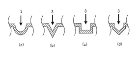
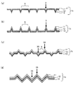
- the top portion (hereinafter sometimes referred to as the top portion of the crease line portion) may have a corner shape or a curvature shape. Specifically, as illustrated in FIG. 2, a semicircle (FIG. 2A), a triangle (FIG. 2B), a quadrangle (FIG. 2C), a trapezoid, a polygon (FIG. 2 d)), semi-elliptical and the like.
- the bottom part or top part of a crease line part is a shape which has a curvature. This is because when the vacuum heat insulating material is bent, stress is applied to the corner portion and a pinhole may be generated.
- the shape of the crease line in plan view is not particularly limited, but is preferably a straight line for ease of bending.
- the depth or height of the crease line portion may be a size that allows the vacuum heat insulating material to be bent at the crease line portion.
- the depth or height of the crease line portion is preferably in the range of 0.5 mm to 2.0 mm, and more preferably in the range of 0.6 mm to 1.5 mm.
- a pinhole or the like may occur during bending depending on the tensile strength of the outer packaging material.
- the vacuum heat insulating material may not be bent at the crease line.
- the depth or height of a crease line part means the length from the surface of a vacuum heat insulating material to the bottom part or top part of a crease line part.
- the line width of the crease line portion is not particularly limited, and can be appropriately set according to the size of the vacuum heat insulating material of the present invention.
- the number of the crease line portions is not particularly limited as long as it is one or more.
- the flexibility of the vacuum heat insulating material improves, so that the vacuum heat insulating material can follow and adhere to a complicated shape such as a curved surface portion or a corner portion. .
- positions the said vacuum heat insulating material and since the heat leak from the said space
- the thickness of the vacuum heat insulating material is reduced at the crease line portion, the heat insulation performance as the whole vacuum heat insulating material may be lowered as the number of the crease line portions is increased.
- the interval between adjacent crease line portions can be appropriately set according to the flexibility required for the vacuum heat insulating material, but is preferably large.
- the arrangement interval of the crease line portions is small, the number of crease line portions can be increased and the flexibility of the vacuum heat insulating material is increased, while the overall thickness of the vacuum heat insulating material is reduced and the heat insulating performance is reduced. Because there is.
- the arrangement interval of the crease line portions is preferably larger than 1 mm, for example, and more preferably 3 mm or more.
- the flexibility required for the vacuum heat insulating material of the present invention is obtained. It can be designed accordingly.
- FIG. 1 (a) a pattern in which the vacuum heat insulating material is arranged in one vertical or horizontal direction is exemplified, but the present invention is not limited to this.
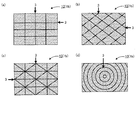
- Other planar patterns include, for example, a diagonal pattern in one direction, a vertical and horizontal grid pattern as shown in FIG. 3A, a diagonal pattern as shown in FIG. Examples thereof include a triangular lattice pattern as shown in (c) and a concentric pattern as shown in FIG.
- FIG. 3 is an explanatory diagram showing an example of a pattern in plan view of the crease line portion.
- the cross-sectional pattern of the crease line part viewed from the side surface of the vacuum heat insulating material can be appropriately designed according to the flexibility required for the vacuum heat insulating material of the present invention. I can do it.
- all the crease line portions 3 may have a convex shape on the core material 2 side, and all the crease line portions have a convex shape on the opposite side to the core material. It may be a pattern.
- the pattern which the crease line part which forms convex shape on the core material side, and the crease line part which forms convex shape on the opposite side to the core material may be mixed alternately or at random.
- a flat portion along a surface formed by the entire outer packaging material between adjacent crease line portions it is preferable to place a flat portion along a surface formed by the entire outer packaging material between adjacent crease line portions. This is because the flatness of the entire vacuum heat insulating material of the present invention can be maintained.
- a pattern in which a crease line portion having a convex shape on the core material side and a crease line portion having a convex shape on the opposite side to the core material are alternately mixed via a flat portion is preferable.
- a bellows pattern in which a crease line portion having a convex shape on the core material side and a crease line portion having a convex shape on the opposite side to the core material are alternately continued without a flat portion may be used.
- the crease line portion may be provided on at least one of the surfaces of the facing outer packaging material, but it is preferable that the facing outer packaging materials each have a crease line portion. This is because the vacuum heat insulating material of the present invention can be easily bent in a desired direction and the flexibility is improved.
- both the opposing outer packaging materials 1b are arranged with a plurality of crease line portions 3 forming a convex shape on the core material 2 side.
- a plurality of crease line portions 3 having a convex shape on the opposite side to the core material 2 are arranged as shown in FIG. 4B. It may have the same pattern.
- one of the facing outer packaging materials 1 b has a crease line portion 3 A that forms a convex shape on the core material 2 side, and the other has a convex shape on the opposite side to the core material 2.
- the crease line part 3B which comprises.
- one of the outer packaging materials has a crease line portion that forms a convex shape on the core material side
- the other outer packaging material has the crease line portion that forms a convex shape on the side opposite to the core material
- the crease line part of the outer packaging material and the crease line part of the other outer packaging material are in positions facing each other.
- at this time when the crease line portion of one of the outer packaging materials and the crease line portion of the other outer packaging material are opposed to each other, at least a part of them is viewed from the thickness direction of the entire outer packaging material. It is preferable to overlap.
- the vacuum heat insulating material of the present invention can be bent in both directions, and the workability can be further improved. Moreover, it is because the thickness of the core material of the part in which a crease line part is located can be ensured, and the fall of the heat insulation performance of a vacuum heat insulating material can be suppressed.
- both of the facing outer packaging materials may have a pattern in which a crease line portion having a convex shape on the core material side and a crease line portion having a convex shape on the opposite side to the core material are mixed.
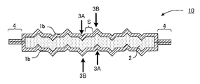
- the opposing outer packaging material 1 b includes a crease line portion 3 A that has a convex shape on the core material 2 side and a crease line portion 3 B that has a convex shape on the opposite side to the core material 2.
- a crease line part forming a convex shape on the core material side and a crease line part forming a convex shape on the opposite side to the core material
- You may have the bellows pattern which continues alternately without interposing a flat part.
- crease line portion that forms a convex shape on the core material side in one outer packaging material and the crease line portion that forms a convex shape on the opposite side to the core material in the other outer packaging material. .
- 4 and 5 are schematic cross-sectional views showing other examples of the vacuum heat insulating material of the present invention.
- the crease line portion may be provided at least in a region in contact with the core material of the outer packaging material, but may be provided on an end portion of the vacuum heat insulating material. This is because the flexibility at the end of the vacuum heat insulating material of the present invention is also improved.
- outer packaging material in the present invention is opposed so as to cover the core material, and the periphery of the opposed outer packaging material is sealed.
- the outer packaging material in the present invention may be any material as long as it can cover the core material and has a gas barrier property, and a material in which a protective layer, a gas barrier layer, and a heat welding layer are laminated at least in this order is usually used.
- a material in which a protective layer, a gas barrier layer, and a heat welding layer are laminated at least in this order is usually used.
- the said thermal welding layer is a site
- the material of the heat-welding layer is preferably a thermoplastic resin because it can be melted and fused by heating.
- a polyolefin resin such as polyethylene or unstretched polypropylene (CPP), a polyvinyl acetate resin , Polyvinyl chloride resin, poly (meth) acrylic resin, urethane resin and the like.
- the melting point of the heat-welded layer is preferably in the range of 80 ° C. to 300 ° C., for example, and more preferably in the range of 100 ° C. to 250 ° C.
- the thickness of the heat welding layer is preferably within a range of 20 ⁇ m to 100 ⁇ m, for example, preferably within a range of 25 ⁇ m to 90 ⁇ m, and particularly preferably within a range of 30 ⁇ m to 80 ⁇ m.
- the thickness of the heat-welded layer is larger than the above range, the gas barrier property of the outer packaging material may be lowered.
- the thickness is smaller than the above range, the adhesive force may not be obtained.
- (B) Gas barrier layer The said gas barrier layer is a site
- the gas barrier layer examples include a metal foil such as aluminum, nickel, stainless steel, iron, copper, and titanium, a vapor deposition film in which an inorganic substance such as metal, metal oxide, and silicon oxide is vapor-deposited on one side of the resin film; Those generally used as a gas barrier layer such as those provided with a gas barrier coating film of a gas barrier composition containing at least one of an alcohol-based resin and an ethylene vinyl alcohol copolymer can also be used.
- the gas barrier layer may be a single layer or a multilayer body in which layers made of the same material or layers made of different materials are laminated.
- the gas barrier layer may be subjected to a surface treatment such as a corona discharge treatment from the viewpoint that the gas barrier performance and the adhesion with other layers can be improved.
- the thickness of the gas barrier layer is, for example, preferably in the range of 2 ⁇ m to 50 ⁇ m, and more preferably in the range of 5 ⁇ m to 12 ⁇ m. If the thickness of the gas barrier layer is smaller than the above range, pinholes and the like are likely to occur when forming the crease line portion, and the gas barrier property may be deteriorated. This is because heat bridge is likely to occur in the vacuum heat insulating material, and the heat insulating performance may be deteriorated.
- an oxygen permeability is not more than 0.5cc ⁇ m -2 ⁇ day -1, is preferably Among them 0.1cc ⁇ m -2 ⁇ day -1 or less. It is preferable that water vapor permeability is not more than 0.2cc ⁇ m -2 ⁇ day -1, is preferably Among them 0.1cc ⁇ m -2 ⁇ day -1 or less.
- oxygen and water vapor permeability of the gas barrier layer is within the above-described range, it is possible to make it difficult for moisture, gas, and the like that have permeated from the outside to penetrate into the inner core material.
- the oxygen transmission rate is determined based on JIS-K-7126B using an oxygen transmission measurement device (Oxtran, manufactured by MOCON, USA) under the conditions of a temperature of 23 ° C. and a humidity of 90% RH. It is a measured value.
- the water vapor permeability is a value measured using a water vapor permeability measuring device (manufactured by MOCON, USA, PERMATRAN) under the conditions of a temperature of 40 ° C. and a humidity of 90% RH.
- the said protective layer is a site
- the protective layer preferably has sufficient strength to protect the inside of the vacuum heat insulating material of the present invention, and is excellent in heat resistance, moisture resistance, pinhole resistance, puncture resistance, and the like.
- the protective layer may be any layer using a resin having a melting point higher than that of the heat welding layer, and may be in the form of a sheet or film.
- a resin having a melting point higher than that of the heat welding layer examples include sheets or films of nylon resin, polyester resin, polyamide resin, polypropylene resin, and the like.
- the protective layer may be a single layer, or may be a multilayer formed by laminating layers made of the same material or layers made of different materials.
- the protective layer may be subjected to a surface treatment such as a corona discharge treatment from the viewpoint of improving the adhesion with other layers.
- the thickness of the protective layer is not particularly limited as long as it can protect the heat welding layer and the gas barrier layer, but is generally about 5 ⁇ m to 80 ⁇ m.
- each layer constituting the outer packaging material may be directly contacted and laminated, or may be laminated via an interlayer adhesive.
- an interlayer adhesive agent the adhesive agent generally used for the outer packaging material for vacuum heat insulating materials can be used.
- the outer packaging material may have a plurality of protective layers or gas barrier layers.
- two or more gas barrier layers may be provided between the heat welding layer and the protective layer, and two or more protective layers may be provided on the heat welding layer and the gas barrier layer. Further, another protective layer may be provided between the heat welding layer and the gas barrier layer.
- the outer packaging material may have an arbitrary layer such as an anchor coat layer or a pinhole-resistant layer.
- the film thickness of the outer packaging material is not particularly limited, but the crease line portion can be formed by a method to be described later, and may be a thickness having a desired gas barrier property, for example, 30 ⁇ m to 200 ⁇ m. Is preferably within the range of 50 ⁇ m to 150 ⁇ m.
- the tensile strength of the outer packaging material is preferably 50N or more, and more preferably 80N or more. This is because breakage or the like hardly occurs when the vacuum heat insulating material of the present invention is bent.
- the tensile strength is a value measured based on JIS-Z-1707.
- the method for laminating the outer packaging material is not particularly limited as long as it is a method that can laminate each layer so that one outermost layer has a protective layer and the other outermost layer has a heat-welded layer, A known laminating method such as a dry lamination method or an extrusion method can be used.
- Core material The core material in this invention is covered with the said outer packaging material, and is included in an outer packaging material.
- the core material is arrange
- the core material is preferably plate-shaped.
- the said core material is plate-shaped in the inside of the vacuum heat insulating material of this invention that the main material of the core material mentioned later is continuing in the surface along the width
- the core material can be easily disposed at a position facing the crease line portion of the vacuum heat insulating material.
- an outer packaging material has a crease line part, even if it is a case where a plate-shaped core material is used, it becomes possible to bend a vacuum heat insulating material.
- the core material does not need to be completely connected over the entire surface along the width (plane) direction of the vacuum heat insulating material, and there are some cut portions. May be.
- disconnected means the location isolate
- the core material is preferably not more than 100 separations, more preferably not more than 10 separations, from the viewpoint of avoiding disposing as much as possible a portion that is cut at a position facing the crease line portion of the vacuum heat insulating material. preferable.
- the plate-like core material for example, a molded body obtained by molding a main material of a core material described later into a plate shape, or a dense material in which a main material of a core material described later is connected in a plate shape by external pressure inside a vacuum heat insulating material. A collection etc. are mentioned.
- the material generally used as a core material of a vacuum heat insulating material can be used.
- powders such as silica, pearlite, clay, talc, foams such as urethane foam, styrene foam, phenol foam, fiber bodies such as glass fiber, alumina fiber, silica alumina fiber, silica fiber, ceramic fiber, rock wool, etc.
- the main material of these core materials is itself porous. These main materials may be used alone or in combination of two or more materials.
- the core material may contain a getter agent in order to prevent a decrease in the degree of vacuum over time due to a minute amount of moisture or gas that permeates from the outside.
- a getter agent in order to prevent a decrease in heat insulation performance, it is preferable that only the core material and the getter agent are included in the outer packaging material.
- the getter agent it can be a material conventionally used for vacuum heat insulating materials, for example, dosonite, hydrotalcite, metal hydroxide, molecular sieves, silica gel, calcium oxide, zeolite, hydrophobic zeolite, activated carbon, etc. Can be mentioned.
- the core material has a low thermal conductivity.
- a porous material having a core material porosity of 50% or more, particularly 90% or more is preferable.
- the thickness of the core material may be any thickness that can be bent at the crease line, and is appropriately set according to the composition and strength of the outer packaging material.
- the core material can be thickened as the strength of the outer packaging material increases.
- the thickness of the core material after decompression is preferably in the range of 1 mm to 10 mm.
- Vacuum heat insulating material In the present invention, it is preferable that the outer packaging material and the core material are in direct contact with each other. If there is another member between the outer packaging material and the core material, there is a risk that the heat insulation property of the vacuum heat insulating material will decrease due to the decrease in the porosity inside the vacuum heat insulating material or the heat bridge. This is because there is a possibility of inhibiting the flexibility. Therefore, in the present invention, a member that contributes to flexibility is usually unnecessary inside the vacuum heat insulating material.
- the member that contributes to the flexibility is, for example, a metal such as aluminum, iron, SUS, or the like, or an organic resin, and has plastic deformability, such as a corrugated plate shape, a pleated shape, and a bellows shape.
- the outer wrapping material since the outer wrapping material has a crease line portion, it has an advantage that it is possible to impart flexibility to the vacuum heat insulating material without having a member that contributes to flexibility inside the vacuum heat insulating material. .
- the core material may or may not follow the shape of the crease line portion of the outer packaging material, but preferably follows. This is because the core material follows the shape of the crease line portion, whereby the vacuum heat insulating material is further easily bent at the crease line portion. At this time, it is particularly preferable that the core material follows the shape of the crease line portion without any gap. This is because if there is a space between the core material and the crease line portion, heat transfer due to air convection may occur when the degree of vacuum in the space decreases.
- the vacuum heat insulating material of the present invention has a reduced pressure inside and is sealed, and specifically the internal vacuum is preferably 5 Pa or less.
- the thermal conductivity of the vacuum heat insulating material of the present invention is preferably low.
- the thermal conductivity at 25 ° C. is preferably 15 mW ⁇ m ⁇ 1 ⁇ K ⁇ 1 or less, It is preferably 10 mW ⁇ m ⁇ 1 ⁇ K ⁇ 1 or less, particularly preferably 5 mW ⁇ m ⁇ 1 ⁇ K ⁇ 1 or less.
- the heat conductivity is a value measured by a heat flow meter method using a heat conductivity measuring device auto lambda (manufactured by Hidehiro Seiki, HC-074) according to JIS-A-1412-3.
- the vacuum heat insulating material of the present invention preferably has a high gas barrier property. This is because it is possible to prevent a decrease in the degree of vacuum due to penetration of moisture, oxygen, etc. from the outside. Since the gas barrier property of the vacuum heat insulating material is the same as the gas barrier property described in the above-mentioned section “2. Outer packaging material”, description thereof is omitted here.
- manufacturing method As a manufacturing method of the vacuum heat insulating material of this invention, the method of covering a core material using the outer packaging material which attached the crease line beforehand, sealing the periphery of an outer packaging material, and sealing under reduced pressure is preferable. This is because the core material can follow the shape of the crease line portion of the outer packaging material when sealing under reduced pressure.
- the manufacturing method of the vacuum heat insulating material of this invention is demonstrated in the term of the "B. manufacturing method of a vacuum heat insulating material" mentioned later.
- the vacuum heat insulating material of this invention has a heat-source part or a heat retaining part, and can be used for articles
- the “heat source section” refers to a portion that generates heat in the device main body or inside the device when the device itself is driven, and refers to, for example, a power source or a motor.
- the “insulated part” refers to a part that does not have a heat source part in the apparatus main body or inside, but the apparatus is heated by receiving heat from an external heat source.
- a natural refrigerant heat pump water heater registered trademark “Ecocute”
- a refrigerator a rice cooker, a pot, a microwave oven, a commercial oven, an IH cooking heater
- Electric appliances such as OA equipment, vending machines, hot water storage tanks, heat insulation tanks, piping in piping facilities, automobiles, and the like.
- the article preferably has at least one of a curved surface portion and a corner portion.
- the method for manufacturing a vacuum heat insulating material according to the present invention includes a crease line portion forming step for forming a crease line portion in an outer packaging material, and the core material is covered with the outer packaging material on which the crease line portion is formed, and then the inside is covered. And a sealing step of reducing pressure and sealing.
- FIG. 6 is a process diagram showing an example of a method for producing a vacuum heat insulating material according to the present invention.
- FIGS. 6 (b) to 6 (d) illustration of each layer structure of the outer packaging material is omitted.
- an outer packaging material 1a in which at least a protective layer 11, a gas barrier layer 12, and a heat welding layer 13 are laminated is prepared (FIG. 6A).
- an embossing plate cylinder 51a having convex portions on the surface as transfer plates, and an embossing impression cylinder 51b having concave portions that have a male-female relationship with the convex portions and can be engaged with each other, are arranged in a row. Transport in the direction.
- the outer wrapping material 1a is pressed while rotating the embossing plate cylinder 51a in the R1 direction and the embossing pressure drum 51b in the R2 direction to form the crease line portion 3 (FIG. 6B), and the obtained outer packaging material 1b is desired. Cut with the length of.
- the outer packaging material 1b having the crease line portion 3 and the outer packaging material 1a not having the crease line portion are overlapped so that the heat-welded layer is on the inner side, and the edges other than the one side that becomes the opening are sealed.
- it is made into a bag shape, and the core material 2 is put and covered therein, and the inside is sealed and sealed while reducing the pressure Y (FIG. 6C).
- the vacuum heat insulating material 10 which has the crease line part 3 in one of the opposing outer packaging materials can be manufactured (FIG.6 (d)).
- 6B shows a crease line forming process
- FIGS. 6C to 6D show a sealing process.
- a vacuum heat insulating material can be manufactured without using a hydraulic roller, a die press, or the like, by manufacturing a vacuum heat insulating material using an outer packaging material in which a crease line portion is formed in advance. A crease line part can be attached to. Thereby, the vacuum heat insulating material which can be bent in the said crease line part can be obtained.
- the crease line forming step in the present invention is a step of forming a crease line portion in the outer packaging material.
- the outer packaging material may be any material that can cover the core material and has gas barrier properties. Usually, a material in which a protective layer, a gas barrier layer, and a heat welding layer are laminated in at least this order is used. About each layer of the said outer packaging material, since it can be set to be the same as that of each layer of the outer packaging material demonstrated in the term of "A. vacuum heat insulating material", description here is abbreviate
- the method for forming the crease line portion on the outer packaging material is not particularly limited as long as it can be formed so that the crease line portion has a desired shape, pattern, or the like.
- a method for example, a first aspect in which an outer packaging material is pressed with a transfer plate having a concavo-convex shape for transferring a crease line portion on the surface (hereinafter sometimes referred to as an embossed plate), an outer packaging material
- the method of forming the crease line portion will be described separately for each aspect.
- This aspect is the method of pressing an outer packaging material with the transfer plate which has uneven
- a method of transferring and forming a crease line portion by pressing an outer packaging material between an embossed plate cylinder and an embossed impression cylinder, a transfer plate having convex portions on a lower plate and an upper plate of a lithographic press, and a concave portion examples thereof include a method in which a transfer plate is provided and a crease line portion is transferred and formed by pressing the outer packaging material between the upper plate and the lower plate from above and below.
- the embossing impression cylinder and the embossing plate cylinder may be referred to as an embossing roll.
- the crease line portion can be formed by transferring the shape of the convex portion of the transfer plate to the outer packaging material.
- the method of using an embossing roll as the transfer plate is the same as the content described in FIG. 6B described above, and thus the description thereof is omitted here.
- the transfer plate can be pressed while moving the outer packaging material, so that it becomes easy to continuously form the crease line portion.
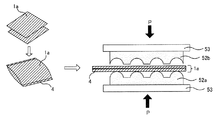
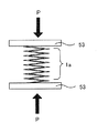
- a cylindrical shape having two end portions 4 a by overlapping two outer packaging materials 1 a and adhering two opposite sides first, a cylindrical shape having two end portions 4 a by overlapping two outer packaging materials 1 a and adhering two opposite sides. And Next, a transfer plate 52a having convex portions is arranged on the lower plate of the lithographic press 53, and a transfer plate 52b having concave portions meshing with the convex portions of the transfer plate 52a is arranged on the upper plate, and the upper and lower sides are passed through the outer packaging material 1a. Press P. Thereby, the shape of the convex part of the transcription
- the outer packaging material can be stopped and the transfer plate can be pressed. Therefore, it is easy to prevent a crease line portion from being formed at the bonded portion of the outer packaging material. Thereby, in the obtained vacuum heat insulating material, it is possible to make it difficult for outside air to enter from the sealed end.
- illustration about the layer structure of an outer packaging material is abbreviate
- the transfer plate used in this embodiment has a concavo-convex shape on the surface.
- the shape of the crease line is formed by the convex portion of the transfer plate.
- the transfer plate may be a roll or a lithographic plate.
- the material of the transfer plate is not particularly limited as long as a desired uneven shape can be formed and a crease line portion having a clear outline can be formed on the outer packaging material by pressing.
- a metal, a ceramic, resin, etc. are mentioned.
- the shape of the convex portion of the transfer plate is not particularly limited as long as it can form a crease line portion having a desired shape. Specifically, since the cross-sectional shape of the convex portion can be the same as the cross-sectional shape of the crease line portion described in the section “A. Vacuum heat insulating material”, description thereof is omitted here. In the present invention, it is preferable that the top of the convex portion of the transfer plate has a curvature. This is because when the top of the convex portion has a corner, when the crease line portion is formed by pressing the transfer plate against the outer packaging material, stress may be applied to the corner and a pinhole may occur in the outer packaging material.
- the pattern of the transfer plate in plan view can be appropriately designed according to the flexibility required for the intended vacuum heat insulating material.
- the pattern in plan view of the transfer plate can be the same as the pattern in plan view of the crease line portion described in the section “A. Vacuum heat insulating material”.
- the height of the convex portion of the transfer plate may be a height that can form a crease line in the outer packaging material by pressing, but if it is too high, a pinhole or the like may occur in the outer packaging material when pressed. Therefore, it is preferable to set appropriately according to the thickness of the gas barrier layer of the outer packaging material, the tensile strength of the outer packaging material, and the like. For example, when the thickness of the gas barrier layer and the tensile strength of the outer packaging material are within the range described in the section “A. Vacuum heat insulating material”, the height of the convex portion of the transfer plate is greater than 1 mm and less than 3 mm. It is preferable that it is about 2 mm among them.
- the height of the convex portion of the transfer plate refers to the length from the surface of the transfer plate to the highest vertex of the convex portion.
- the pitch width of the convex portions of the transfer plate can be appropriately set according to the use of the obtained vacuum heat insulating material, required flexibility, etc., but is preferably large. This is because if the pitch width of the convex portions is too small, a large number of crease line portions can be provided, while the overall thickness of the obtained vacuum heat insulating material becomes small and the heat insulating performance may be lowered. In addition, since the pitch width is too small, it may be difficult to form a crease line portion having a clear outline according to this aspect.
- the pitch width is the same as the arrangement interval of the crease line portions described in the section “A. Vacuum heat insulating material”, and thus the description thereof is omitted here.
- the pressing force when pressing the transfer plate against the outer packaging material is not particularly limited as long as the outer packaging material can follow the convex portion of the transfer plate, and the material and thickness of the outer packaging material to be used
- the thickness can be appropriately set according to the tensile strength, the height of the convex portion of the transfer plate, and the like.
- a larger pressing force is preferable from the viewpoint that a crease line portion having a clear outline can be formed on the outer packaging material.
- the pressing force is too large, pinholes, cracks, etc. may occur in the outer packaging material. It is preferably in the range of cm 2 to 80 kgf / cm 2 .
- the crease line portion may be formed on one outer packaging material, or the crease line portion may be formed on the outer packaging material in a state where two or more sheets are overlapped.
- the number of sheets that can be stacked is the crease line portion having a desired height or depth on each outer packaging material by pressing the transfer plate. Any number of sheets can be formed, and the number is appropriately set according to the thickness of the crease line portion per sheet, pressing conditions, and the like.
- the crease line portion may be formed after adhering at least one side of the overwrapped outer packaging material.
- Adhering at least one side of the overlapped outer packaging material usually means stacking two outer packaging materials and adhering at least one side of the peripheral edges. This is because this method can prevent misalignment when forming the crease line portion.
- it becomes easier to insert the core material along the bonded one side, the crease line portion disposed on one outer packaging material, and the other outer packaging material This is because it is possible to face the crease line portion disposed on the substrate with the core material interposed therebetween.
- an embossing roll as the transfer plate, it is preferable to bond at least one side along the direction in which the outer packaging material advances.
- the crease line part after adhering two or more continuous sides of the outer packaging material in an overlapped state.
- the outer packaging material becomes a bag shape, and an inner corner of the bag is formed.
- the outer packaging material can be formed into a cylindrical shape by adhering at least two opposing sides of the outer packaging material. This is because by making the outer packaging material cylindrical or bag-like, the core material can be easily inserted and the core material can be easily sealed.
- a crease line portion may be formed in the outer packaging material in a folded state.
- the state in which the outer packaging material is folded usually means a state in which the outer packaging material is folded in two so that opposing sides of one outer packaging material overlap each other. According to this method, one side is connected by folding the outer packaging material, there is no need to separately adhere at least one side of the outer packaging material, and the crease line portion is formed in a state where the outer packaging material is folded, The misalignment of the crease line can be prevented.
- a crease line portion may be formed by stacking a plurality of outer packaging materials in which at least one side is bonded or folded and pressing the transfer plate.
- the transfer plate can be continuously pressed onto the outer packaging material, a plurality of outer packaging materials can be obtained by cutting into desired dimensions after pressing.
- the crease line portion can be formed continuously, Further, it is possible to produce a cylindrical or bag-shaped outer packaging material by cutting and heat-welding at a desired position.
- This aspect is a method of pressing an outer packaging material in a state of being temporarily folded into an uneven shape.
- the outer packaging material 1 a is preliminarily folded into a desired pattern and sandwiched between the lithographic press 53, and by pressing P from above and below, the temporarily folded portion is defined as a crease line portion. It is a method to do. This method does not require a transfer plate.
- illustration is abbreviate
- one outer packaging material may be temporarily folded, or two or more outer packaging materials may be stacked and temporarily folded. Moreover, at least one side of the outer packaging material to be temporarily folded may be sealed. Since these reasons are the same as those described in the above-mentioned section “(a) First aspect”, description thereof is omitted here.
- the press conditions in this aspect it can set suitably according to the thickness, tensile strength, number of sheets, etc. of the outer packaging material to be used.
- FIG. 9 is a schematic sectional drawing which shows the example of the outer packaging material in which the crease line part was formed by this process.
- a cross-sectional pattern of the crease line portion formed in this step for example, as shown in FIG. 9A, all the crease line portions 3 are directed from the protective layer 11 side of the outer packaging material 1b toward the thermal welding layer 13 side.
- 9B a pattern having a convex shape from the heat welding layer 13 side toward the protective layer 11 side, as shown in FIG. 9C, and a heat welding layer 13 as shown in FIG.
- Examples include a pattern in which a crease line portion 3A having a convex shape from the side toward the protective layer 11 side and a crease line portion 3B having a convex shape from the protective layer 11 side toward the heat welding layer 13 side are mixed.
- the flatness as a whole of the obtained vacuum heat insulating material can be maintained by passing the flat portion S along the surface formed by the entire outer packaging material between the adjacent crease line portions.
- the pattern in which the crease line portions 3A and 3B are mixed as shown in FIG. 9C is preferable in that the obtained vacuum heat insulating material can be bent in both directions, and the workability can be further improved. .
- FIG. 9C is preferable in that the obtained vacuum heat insulating material can be bent in both directions, and the workability can be further improved.
- the crease line portion 3A forming a convex shape from the heat welding layer 13 side toward the protective layer 11 side and the convex shape from the protective layer 11 side toward the heat welding layer 13 side.
- the crease line portion 3B formed may be a bellows pattern in which the crease line portion 3B is alternately and continuously repeated without a flat surface. Note that reference numerals not described in FIG. 9 are the same as those in FIG.
- the details of the crease line portion formed in this step are the same as the details of the crease line portion described in the section “A. Vacuum heat insulating material”, and thus the description thereof is omitted here.
- the sealing step in the present invention is a step of covering the core material using the outer packaging material on which the crease line portion is formed, and then reducing the pressure inside to seal it.
- Core material About the core material used in this process, it can be made to be the same as that of the content demonstrated by the term of "A. Vacuum heat insulating material 3. Core material.”
- the main material of the core material such as powder or fiber body may be used as it is, or a molded body obtained by molding the main material of the core material into a plate shape having a thickness described later may be used. .
- the thickness of the core material is preferably a size that can be bent at the crease line after decompression, and is appropriately set depending on the strength of the outer packaging material.
- the thickness of the core material is in the range of 1 mm to 50 mm, particularly in the range of 3 mm to 40 mm. In particular, the range of 5 mm to 30 mm is preferable.
- the outer packaging material is opposed so as to cover the core material, and the crease line portion is disposed on at least one of the opposed outer packaging materials.
- the outer packaging material is overlapped so that the heat-welded layers face each other on the inside, and the outer periphery is sealed except for one side that becomes an opening to form a bag, and the core material is inserted therein to decompress the inside.
- Method of sealing placing the outer packaging material on the two opposite faces of the core material so that the heat-welded layer is on the inside, sealing the outer packaging material so that part of the periphery is open, and then reducing the inside Then, a sealing method or the like can be used.
- the crease line portion can be arranged when the core material is covered, by using at least one of the opposing outer wrapping materials as the wrapping material on which the crease line portion is formed.
- the outer packaging material that covers the core material only needs to have the crease line portion disposed on at least one of the outer packaging materials facing each other through the core material, but it is preferable that the crease line portion is disposed on both of the opposed outer packaging materials.
- the crease line portions of the facing outer packaging material may be the same or different in number, shape, pattern, etc., but are preferably the same.
- the crease line portion in one outer packaging material and the crease line portion in the other outer packaging material are opposed to each other, so that they are the thickness of the entire outer packaging material. It is preferable that at least a part overlap when viewed from the direction.
- the forming method when the outer packaging material is formed into a bag shape is not particularly limited.
- the outer packaging material in which the crease line portion is formed is folded and overlapped, and the rim line portion except the one side that becomes the opening is bonded
- a method in which the outer packaging material formed with the wrapping material and the outer packaging material without the crease line portion are overlapped and the peripheral edge excluding one side serving as the opening is bonded can be used.
- a method of forming a crease line portion by stacking the outer packaging material and bonding at least one side, and bonding the remaining peripheral edge excluding the one side that becomes the opening can be used.
- the heating temperature at the time of adhering the periphery of the outer packaging material is appropriately selected depending on the composition of the thermal welding layer of the outer packaging material and is usually higher than the melting point of the resin used for the thermal welding layer and lower than the decomposition temperature. It is preferable to set within the temperature range.
- the width of the sealing surface at the periphery of the outer packaging material that is, the width of the end portion of the vacuum heat insulating material in the present invention is not particularly limited, but is preferably small enough not to cause peeling. This is because the end portion does not have a heat insulating function, so that if the width of the end portion is too large, the effective area contributing to heat insulation is reduced with respect to the entire area of the vacuum heat insulating material.
- the main material of the powder or fibrous core material may be directly inserted into the outer packaging material in a bag shape, and the main material of the core material is plate-shaped. You may insert the molded object which shape
- the number of the molded bodies covered by a pair of opposed outer packaging materials may be one or plural, but preferably one.
- the method for reducing the pressure and sealing the inside of the core material covered with the outer packaging material is not particularly limited as long as the inside can be sealed with a desired degree of vacuum.
- a method of inserting into a vacuum chamber in a state where a core material is put in a bag-like outer packaging material, degassing from the opening and reducing the pressure, and then heat-sealing and sealing the opening can be used.
- the core material may or may not follow the crease line portion of the outer packaging material at the time of decompression, but preferably follows. Especially, it is preferable to make a core material follow the shape of a crease line part without gap. The reason is the same as the reason described in the section “A. Vacuum heat insulating material”.
- the size of the reduced pressure is not particularly limited as long as the inside can have a desired degree of vacuum, but it is preferable that the core can follow the pattern of the crease line portion of the outer packaging material. . Specifically, it is preferable to reduce the pressure so that the internal pressure is 5 Pa or less.
- Step 3 The present invention may have arbitrary steps in addition to the steps described above.
- an outer packaging material preparing step for forming an outer packaging material in which a protective layer, a gas barrier layer, and a heat welding layer are laminated in this order a core material preparing step using the core material as a molded body, an outer packaging material and a core material The drying process etc. which dry is mentioned.
- the outer packaging material for a vacuum heat insulating material according to the present invention is used for a vacuum heat insulating material having a core material and an outer packaging material facing so as to cover the core material, and the periphery of the facing outer packaging material is sealed. It is an outer packaging material for a vacuum heat insulating material and has a crease line portion.
- the outer packaging material for a vacuum heat insulating material of the present invention is the same as the outer packaging material 1b described in FIG. 9, the description thereof is omitted here.
- the outer packaging material for vacuum heat insulation of the present invention is usually formed by laminating a protective layer, a gas barrier layer, and a heat welding layer in at least this order.
- the present invention by having the crease line portion, it is possible to bend the vacuum heat insulating material formed using the outer packaging material for vacuum heat insulating material of the present invention with the crease line portion as a trigger.
- the details of the outer packaging material for a vacuum heat insulating material and the bent portion of the present invention are the same as the details of the outer packaging material and the bent portion described in the sections “A. Vacuum heat insulating material” and “B. Manufacturing method of vacuum heat insulating material”. Therefore, the description here is omitted.
- the heat insulating article of the present invention is a heat insulating article having an article having at least one of a curved surface portion and a corner portion, and a vacuum heat insulating material disposed on the article, wherein the vacuum heat insulating material includes a core material and the core.
- the outer packaging material facing the material, the peripheral edge of the facing outer packaging material is sealed, and at least one of the opposed outer packaging materials has a crease line, and the vacuum heat insulation The material is bent at the crease line portion and disposed on at least one of the curved surface portion and the corner portion.
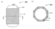
- FIG. 10A is a schematic view showing an example of the heat-insulating article of the present invention
- FIG. 10B is a cross-sectional view taken along the line XX of FIG.
- FIGS. 10A and 10B show an example of a hot water storage tank of a water heater as an article having a curved surface portion.
- goods of this invention arrange
- the vacuum heat insulating material 10 has the crease line portion 3, it is bent at the crease line portion 3 and arranged so as to follow the curved surface portion of the hot water storage tank 21A.
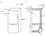
- FIG.11 (a) is a schematic diagram which shows the other example of the heat insulation article of this invention
- FIG.11 (b) is the sectional side view seen from the X direction of Fig.11 (a).
- FIG. 11 (a), (b) shows the example of a refrigerator as an article
- the heat insulation article 20B of the present invention is obtained by arranging the vacuum heat insulating material 10 on an article (refrigerator) 21B having a corner C.
- the refrigerator 21 ⁇ / b> B includes an outer box 22, an inner box 23, and a door 24, and the vacuum heat insulating material 10 is disposed in a space between the outer box 22 and the inner box 23.
- the vacuum heat insulating material 10 has the crease line portion 3, the vacuum heat insulating material 10 is arranged to be bent at the crease line portion 3 and follow the corner portion C.
- the edge part of a vacuum heat insulating material is normally arrange
- the vacuum heat insulating material is bent at the crease line portion and disposed along the curved surface portion or corner portion of the article, a gap is generated between the curved surface portion or corner portion of the article and the vacuum heat insulating material. It becomes difficult and heat insulation performance of a heat insulation article can be maintained because heat leak from the space is controlled.
- the core material is disposed at the position of the crease line portion of the vacuum heat insulating material bent along the curved surface portion and / or corner portion of the article. This is because the thickness of the vacuum heat insulating material at the crease line portion serving as the bent portion can be prevented from being reduced, and the heat insulating performance at the curved surface portion and / or the corner portion of the article can be prevented from decreasing.
- the vacuum heat insulating material in this invention is arrange
- the vacuum heat insulating material has a core material and an outer packaging material facing so as to cover the core material, and a peripheral edge of the facing outer packaging material is sealed, and at least one of the opposed outer packaging materials It has a crease line part.
- the details of the vacuum heat insulating material in the present invention are the same as the contents described in the section “A. Vacuum heat insulating material”, and thus the description thereof is omitted here.
- Article The article in the present invention has at least one of a curved surface portion and a corner portion.
- an article having at least one of a curved surface portion and a corner portion and having a heat retaining and cooling function examples include a hot water storage tank such as a water heater, a heat retaining tank, piping in a piping facility, and the like.
- the article having a corner has, for example, a refrigerator, a vending machine, a showcase, a refrigeration / air-conditioning apparatus, a storage, a box-shaped article such as a heat insulation cold box for transportation, and a double structure of an inner wall and an outer wall. Wall panel etc. are mentioned.
- angular part shall also contain the recessed part and convex part which have on the surface of an article
- the size, shape, etc. of the article are not particularly limited, and are appropriately designed according to the application.
- the heat insulating article of the present invention can be disposed by bending the vacuum heat insulating material at the fold line portion so as to follow the curvature of the curved surface portion of the article, or hit the corner of the article. There may be one or more vacuum heat insulating materials disposed on the article.
- a method of arranging the vacuum heat insulating material on the article there are a method of fixing the vacuum heat insulating material and the article through an adhesive layer, a method of fixing the outside of the vacuum heat insulating material pressed against the article with a resin or a string, and the like. Can be mentioned. Above all, it is preferable to arrange the vacuum heat insulating material and the article so as to be detachable, because it is possible to replace the vacuum heat insulating material whose heat insulating property is lowered.
- the vacuum heat insulating material disposed in a portion other than the curved surface portion or the corner portion of the article may or may not have a fold line portion, but preferably does not have it. This is because the core material located at the fold line portion has a smaller thickness than other portions, and the heat insulation performance may be lowered.
- the present invention is not limited to the above embodiment.
- the above-described embodiment is an exemplification, and this embodiment has substantially the same configuration as the technical idea described in the claims of the present invention, and any device that exhibits the same function and effect is the present embodiment. It is included in the technical scope of the invention.
- a 25 ⁇ m thick nylon film (product name: ONM, manufactured by Unitika Co., Ltd.) with easy adhesion treatment on both sides is applied to the easy adhesion surface of the interlayer adhesive prepared at the above blending ratio. It apply
- a PET film (product name: PET, manufactured by Unitika Co., Ltd.) having a film thickness of 12 ⁇ m whose both surfaces were subjected to easy adhesion treatment as a second protective layer was laminated on the surface of the first protective layer to which an interlayer adhesive was applied.
- an interlayer adhesive was similarly applied at a coating amount of 3.5 g / m 2 on the PET (second protective layer) surface of the obtained two-layer film and dried.
- An Al foil having a film thickness of 6 ⁇ m (product name: 1N30 manufactured by Sumikara Aluminum Foil Co., Ltd.) was laminated as a gas barrier layer on the surface of the second protective layer to which the interlayer adhesive was applied.
- an interlayer adhesive was similarly applied at an application amount of 3.5 g / m 2 on the Al foil (gas barrier layer) surface of the obtained three-layer film and dried.
- Laminate 50 ⁇ m linear (linear) low density polyethylene product name: FC-D, manufactured by Mitsui Chemicals, Inc.
- the outer packaging material in which the crease line part was formed was piled up, and a bag body in which three sides were sealed by thermal welding and the remaining one was an opening was formed.
- a glass wool having a thickness of 1.0 cm is inserted as a core material from the opening of the bag body, and the inside of the bag is depressurized and deaerated to reduce the internal vacuum to 1.0 Pa or less, and the opening is thermally welded. Sealed to obtain a vacuum heat insulating material.
- Example 2 A vacuum heat insulating material was obtained in the same manner as in Example 1 except that the thickness of the core material was 1.5 cm.
- Example 1 A vacuum heat insulating material was obtained in the same manner as in Example 1 except that the crease line portion was not formed on the outer packaging material.
- Example 2 A vacuum heat insulating material was obtained in the same manner as in Example 2 except that the crease line portion was not formed on the outer packaging material.
- Example 3 A vacuum heat insulating material was obtained in the same manner as in Example 1 except that the crease line portion was not formed on the outer packaging material and the thickness of the encapsulating core material was 3.0 cm.
- Examples 3a to 3c A vacuum heat insulating material was obtained in the same manner as in Example 1 except that the crease line portion forming step was performed according to the following procedure. In addition, the obtained vacuum heat insulating material had the crease line part which the outer packaging material which opposes each forms a convex shape in the core material side.
- Embossed plate cylinders having convex portions with a semicircular cross-sectional shape formed on the surface, and embossed impression cylinders having recessed portions meshing with the embossed plate cylinders, arranged in series so that the embossed plate cylinders are on the lower side. And rotated in the opposite direction in synchronism at the same speed.
- the outer packaging material created in Example 1 was passed between the embossing plate cylinder and the embossing impression cylinder, and the embossing plate cylinder and the embossing impression cylinder were meshed to form a crease line portion on the outer packaging material.
- the crease line portion has a convex shape from the protective layer side of the outer packaging material toward the heat-welded layer side, the cross section is semicircular, and a flat portion between adjacent crease line portions.
- the crease line portion has a plane pattern parallel to one side of the outer packaging material.
Landscapes
- Engineering & Computer Science (AREA)
- Chemical & Material Sciences (AREA)
- Combustion & Propulsion (AREA)
- Physics & Mathematics (AREA)
- Mechanical Engineering (AREA)
- Thermal Sciences (AREA)
- General Engineering & Computer Science (AREA)
- Thermal Insulation (AREA)
Applications Claiming Priority (6)
| Application Number | Priority Date | Filing Date | Title |
|---|---|---|---|
| JP2013151144 | 2013-07-19 | ||
| JP2013-151144 | 2013-07-19 | ||
| JP2013151154 | 2013-07-19 | ||
| JP2013-151154 | 2013-07-19 | ||
| JP2014-079597 | 2014-04-08 | ||
| JP2014079597A JP5907204B2 (ja) | 2013-07-19 | 2014-04-08 | 真空断熱材の製造方法 |
Publications (1)
| Publication Number | Publication Date |
|---|---|
| WO2015008533A1 true WO2015008533A1 (ja) | 2015-01-22 |
Family
ID=52346008
Family Applications (1)
| Application Number | Title | Priority Date | Filing Date |
|---|---|---|---|
| PCT/JP2014/063332 Ceased WO2015008533A1 (ja) | 2013-07-19 | 2014-05-20 | 真空断熱材、真空断熱材の製造方法、真空断熱材用外包材、および断熱物品 |
Country Status (2)
| Country | Link |
|---|---|
| JP (1) | JP5907204B2 (enExample) |
| WO (1) | WO2015008533A1 (enExample) |
Cited By (1)
| Publication number | Priority date | Publication date | Assignee | Title |
|---|---|---|---|---|
| WO2017093691A1 (fr) * | 2015-12-02 | 2017-06-08 | Hutchinson | Piece isolante metallique tridimensionnelle |
Families Citing this family (5)
| Publication number | Priority date | Publication date | Assignee | Title |
|---|---|---|---|---|
| JP2018017476A (ja) * | 2016-07-29 | 2018-02-01 | 日立アプライアンス株式会社 | 真空断熱材およびこれを用いた冷蔵庫 |
| JP2018194016A (ja) * | 2017-05-12 | 2018-12-06 | 東芝ホームテクノ株式会社 | 真空断熱材、当該真空断熱材の製造方法及び当該真空断熱材を備える断熱貯蔵庫 |
| JP7484388B2 (ja) * | 2020-04-28 | 2024-05-16 | 大日本印刷株式会社 | 断熱配管及び断熱配管の製造方法 |
| JP7596746B2 (ja) * | 2020-11-27 | 2024-12-10 | 大日本印刷株式会社 | 断熱配管及び真空断熱モジュール |
| US11614271B2 (en) * | 2020-12-29 | 2023-03-28 | Whirlpool Corporation | Vacuum insulated structure with sheet metal features to control vacuum bow |
Citations (8)
| Publication number | Priority date | Publication date | Assignee | Title |
|---|---|---|---|---|
| JP2000097390A (ja) * | 1998-09-22 | 2000-04-04 | Meisei Ind Co Ltd | 断熱パネル及びその製造方法 |
| JP2001336691A (ja) * | 2000-05-25 | 2001-12-07 | Matsushita Refrig Co Ltd | 真空断熱材、及び真空断熱材を用いた冷蔵庫 |
| JP2004232735A (ja) * | 2003-01-30 | 2004-08-19 | Zojirushi Corp | 真空断熱パネル |
| JP2007155065A (ja) * | 2005-12-07 | 2007-06-21 | Nisshinbo Ind Inc | 真空断熱材及びその製造方法 |
| JP2007263186A (ja) * | 2006-03-28 | 2007-10-11 | Hitachi Appliances Inc | 断熱パネル及びそれを用いた機器 |
| JP2008039282A (ja) * | 2006-08-04 | 2008-02-21 | Denso Corp | 貯湯式給湯装置の断熱構造 |
| JP2008121757A (ja) * | 2006-11-10 | 2008-05-29 | Sharp Corp | 真空断熱材と冷蔵庫 |
| JP2010127463A (ja) * | 2008-11-28 | 2010-06-10 | Kaizukogyosho Co Ltd | 真空断熱パネル |
Family Cites Families (2)
| Publication number | Priority date | Publication date | Assignee | Title |
|---|---|---|---|---|
| JP4861715B2 (ja) * | 2006-02-06 | 2012-01-25 | 日立アプライアンス株式会社 | 真空断熱材の製造方法 |
| JP4800153B2 (ja) * | 2006-08-31 | 2011-10-26 | 象印マホービン株式会社 | 真空断熱パネル |
-
2014
- 2014-04-08 JP JP2014079597A patent/JP5907204B2/ja active Active
- 2014-05-20 WO PCT/JP2014/063332 patent/WO2015008533A1/ja not_active Ceased
Patent Citations (8)
| Publication number | Priority date | Publication date | Assignee | Title |
|---|---|---|---|---|
| JP2000097390A (ja) * | 1998-09-22 | 2000-04-04 | Meisei Ind Co Ltd | 断熱パネル及びその製造方法 |
| JP2001336691A (ja) * | 2000-05-25 | 2001-12-07 | Matsushita Refrig Co Ltd | 真空断熱材、及び真空断熱材を用いた冷蔵庫 |
| JP2004232735A (ja) * | 2003-01-30 | 2004-08-19 | Zojirushi Corp | 真空断熱パネル |
| JP2007155065A (ja) * | 2005-12-07 | 2007-06-21 | Nisshinbo Ind Inc | 真空断熱材及びその製造方法 |
| JP2007263186A (ja) * | 2006-03-28 | 2007-10-11 | Hitachi Appliances Inc | 断熱パネル及びそれを用いた機器 |
| JP2008039282A (ja) * | 2006-08-04 | 2008-02-21 | Denso Corp | 貯湯式給湯装置の断熱構造 |
| JP2008121757A (ja) * | 2006-11-10 | 2008-05-29 | Sharp Corp | 真空断熱材と冷蔵庫 |
| JP2010127463A (ja) * | 2008-11-28 | 2010-06-10 | Kaizukogyosho Co Ltd | 真空断熱パネル |
Cited By (1)
| Publication number | Priority date | Publication date | Assignee | Title |
|---|---|---|---|---|
| WO2017093691A1 (fr) * | 2015-12-02 | 2017-06-08 | Hutchinson | Piece isolante metallique tridimensionnelle |
Also Published As
| Publication number | Publication date |
|---|---|
| JP5907204B2 (ja) | 2016-04-26 |
| JP2015038374A (ja) | 2015-02-26 |
Similar Documents
| Publication | Publication Date | Title |
|---|---|---|
| JP5907204B2 (ja) | 真空断熱材の製造方法 | |
| KR101286342B1 (ko) | 진공단열재용 복합심재, 그 제조방법 및 이를 이용한 진공단열재 | |
| CN102859251B (zh) | 用于隔热的抽真空的扁平成型件及其制造方法 | |
| KR101260557B1 (ko) | 진공 단열 패널 및 이를 제조하는 방법 | |
| CN104582958A (zh) | 高温成型用绝热膜和利用该绝热膜的真空绝热材料及其制备方法 | |
| KR101353647B1 (ko) | 진공단열재용 심재 및 이를 이용한 진공단열재 | |
| KR102201266B1 (ko) | 진공 단열재 | |
| JP2007155065A (ja) | 真空断熱材及びその製造方法 | |
| CN1853922B (zh) | 真空绝热材料及其制造方法 | |
| JP2014228135A (ja) | 真空断熱材の製造方法および真空断熱材 | |
| TWI599737B (zh) | 真空隔熱材料、隔熱箱以及真空隔熱材料之製造方法 | |
| TW494207B (en) | Evacuated panel for thermal insulation of cylindrical bodies | |
| JP2009156353A (ja) | 真空断熱材およびそれを用いた機器 | |
| TWI604150B (zh) | Vacuum heat insulation material and heat insulation box | |
| JP2007155135A (ja) | 真空断熱材及びその製造方法 | |
| JPWO2016190176A1 (ja) | 貫通穴付き積層断熱体および断熱構造 | |
| JP2007321925A (ja) | 真空断熱材及びその製造方法 | |
| JP2011089740A (ja) | 袋体、および真空断熱材 | |
| JP2015038375A (ja) | 真空断熱材の製造方法 | |
| WO2016157931A1 (ja) | 真空断熱材用外包材、真空断熱材、および真空断熱材付き機器 | |
| JP5517150B2 (ja) | 真空断熱パネル用包装材及び真空断熱パネル | |
| KR101944162B1 (ko) | 고온 진공단열패널용 외피재, 이를 이용한 고온 진공단열패널 및 이의 제조방법 | |
| JP6422713B2 (ja) | 袋体及び当該袋体を用いた真空断熱材 | |
| JP2007138976A (ja) | 真空断熱材及びその製造方法 | |
| JP5377451B2 (ja) | 真空断熱材およびこの真空断熱材を用いた断熱箱 |
Legal Events
| Date | Code | Title | Description |
|---|---|---|---|
| 121 | Ep: the epo has been informed by wipo that ep was designated in this application |
Ref document number: 14826108 Country of ref document: EP Kind code of ref document: A1 |
|
| NENP | Non-entry into the national phase |
Ref country code: DE |
|
| 122 | Ep: pct application non-entry in european phase |
Ref document number: 14826108 Country of ref document: EP Kind code of ref document: A1 |