WO2014208488A1 - 焦点調節装置、カメラシステム、及び焦点調節方法 - Google Patents
焦点調節装置、カメラシステム、及び焦点調節方法 Download PDFInfo
- Publication number
- WO2014208488A1 WO2014208488A1 PCT/JP2014/066521 JP2014066521W WO2014208488A1 WO 2014208488 A1 WO2014208488 A1 WO 2014208488A1 JP 2014066521 W JP2014066521 W JP 2014066521W WO 2014208488 A1 WO2014208488 A1 WO 2014208488A1
- Authority
- WO
- WIPO (PCT)
- Prior art keywords
- focus
- lens
- phase difference
- difference information
- conversion coefficient
- Prior art date
Links
Images


Classifications
-
- H—ELECTRICITY
- H04—ELECTRIC COMMUNICATION TECHNIQUE
- H04N—PICTORIAL COMMUNICATION, e.g. TELEVISION
- H04N23/00—Cameras or camera modules comprising electronic image sensors; Control thereof
- H04N23/60—Control of cameras or camera modules
- H04N23/67—Focus control based on electronic image sensor signals
- H04N23/672—Focus control based on electronic image sensor signals based on the phase difference signals
-
- G—PHYSICS
- G02—OPTICS
- G02B—OPTICAL ELEMENTS, SYSTEMS OR APPARATUS
- G02B7/00—Mountings, adjusting means, or light-tight connections, for optical elements
- G02B7/28—Systems for automatic generation of focusing signals
-
- G—PHYSICS
- G02—OPTICS
- G02B—OPTICAL ELEMENTS, SYSTEMS OR APPARATUS
- G02B7/00—Mountings, adjusting means, or light-tight connections, for optical elements
- G02B7/28—Systems for automatic generation of focusing signals
- G02B7/34—Systems for automatic generation of focusing signals using different areas in a pupil plane
-
- G—PHYSICS
- G03—PHOTOGRAPHY; CINEMATOGRAPHY; ANALOGOUS TECHNIQUES USING WAVES OTHER THAN OPTICAL WAVES; ELECTROGRAPHY; HOLOGRAPHY
- G03B—APPARATUS OR ARRANGEMENTS FOR TAKING PHOTOGRAPHS OR FOR PROJECTING OR VIEWING THEM; APPARATUS OR ARRANGEMENTS EMPLOYING ANALOGOUS TECHNIQUES USING WAVES OTHER THAN OPTICAL WAVES; ACCESSORIES THEREFOR
- G03B13/00—Viewfinders; Focusing aids for cameras; Means for focusing for cameras; Autofocus systems for cameras
- G03B13/32—Means for focusing
- G03B13/34—Power focusing
- G03B13/36—Autofocus systems
-
- G—PHYSICS
- G03—PHOTOGRAPHY; CINEMATOGRAPHY; ANALOGOUS TECHNIQUES USING WAVES OTHER THAN OPTICAL WAVES; ELECTROGRAPHY; HOLOGRAPHY
- G03B—APPARATUS OR ARRANGEMENTS FOR TAKING PHOTOGRAPHS OR FOR PROJECTING OR VIEWING THEM; APPARATUS OR ARRANGEMENTS EMPLOYING ANALOGOUS TECHNIQUES USING WAVES OTHER THAN OPTICAL WAVES; ACCESSORIES THEREFOR
- G03B17/00—Details of cameras or camera bodies; Accessories therefor
- G03B17/02—Bodies
- G03B17/12—Bodies with means for supporting objectives, supplementary lenses, filters, masks, or turrets
- G03B17/14—Bodies with means for supporting objectives, supplementary lenses, filters, masks, or turrets interchangeably
-
- H—ELECTRICITY
- H04—ELECTRIC COMMUNICATION TECHNIQUE
- H04N—PICTORIAL COMMUNICATION, e.g. TELEVISION
- H04N23/00—Cameras or camera modules comprising electronic image sensors; Control thereof
- H04N23/60—Control of cameras or camera modules
- H04N23/66—Remote control of cameras or camera parts, e.g. by remote control devices
- H04N23/663—Remote control of cameras or camera parts, e.g. by remote control devices for controlling interchangeable camera parts based on electronic image sensor signals
Definitions
- the present invention relates to a focus adjustment apparatus, a camera system, and a focus adjustment method for performing focus adjustment by a phase difference AF method.
- the phase difference AF method is used for focus adjustment in a camera system or the like.
- a two-image interval value also referred to as image phase difference information
- the two-image interval value is converted into a defocus amount using a conversion coefficient (also referred to as AF sensitivity).
- this conversion coefficient varies depending on individual variations of image pickup elements and individual variations of photographing lenses.
- the solid-state variation of the image sensor the influence of the variation due to the quality of the on-chip microlens for pupil division is large.
- the variation in the photographing lens is greatly affected by the variation in the aperture diameter of the aperture.
- Patent Document 1 An imaging apparatus that corrects such a conversion coefficient is described in Patent Document 1.
- the pixel data of the focus detection pixels acquired a plurality of times with the passage of time are added to obtain a two-image interval value as image data and converted into a defocus amount, the taking lens during this passage of time
- the defocus amount is calculated by correcting the conversion coefficient.
- Patent Document 1 discloses correcting the conversion coefficient related to the temporal change of the optical system.
- correcting the variation of the conversion coefficient caused by the individual variation of the image sensor or the interchangeable lens.
- it is possible to adjust to absorb the influence of the individual variation of the image pickup device but it is very difficult to adjust the individual variation of the interchangeable lens.
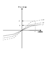
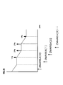
- the horizontal axis represents two image intervals
- the vertical axis represents the defocus amount
- L1 to L3 are conversion coefficient curves, which vary due to individual variations between the image sensor and the interchangeable lens.
- the true conversion coefficient curve when the two-image interval value is X is L3
- the conversion coefficient curve currently used is L1
- the defocus amount is y
- the true defocus amount y ′ A smaller value is calculated.
- the lens drive becomes insufficient, and it is necessary to detect the two-image interval value again and perform lens drive (also referred to as LD).
- the present invention has been made in view of such circumstances, and provides a focus adjustment device, a camera system, and a focus adjustment method that can be corrected so as to obtain an accurate conversion coefficient in each focus adjustment device. With the goal.
- a focus adjustment apparatus includes a focus detection unit that detects image phase difference information based on a light beam that has passed through a photographing optical system including a focus lens, and uses the image phase difference information as a defocus amount.
- a storage unit that stores a conversion coefficient to be converted, a focus adjustment unit that converts the image phase difference information into a defocus amount using the conversion coefficient, and moves the focus lens based on the defocus amount to perform focus adjustment;
- the focus adjustment unit converts the first image phase difference information detected by the focus detection unit into a defocus amount using the conversion coefficient, and moves the focus lens based on the defocus amount.
- the second image phase difference information is detected by the focus detection unit, and the conversion coefficient is corrected based on the second image phase difference information and stored in the storage unit.
- a camera system is a camera system having an interchangeable lens having a photographing optical system and a camera body to which the interchangeable lens can be attached, wherein the interchangeable lens is included in the photographing optical system.
- a lens control unit that controls movement of the focus lens; a lens storage unit that stores identification information unique to the interchangeable lens; and a lens communication unit that communicates with the camera body.
- a focus detection unit that detects image phase difference information based on a light beam that has passed through an optical system, and a main body that stores a conversion coefficient for converting the image phase difference information into a defocus amount corresponding to the identification information of the interchangeable lens
- the conversion coefficient stored in the main body storage unit is selected based on the identification information of the interchangeable lens acquired from the lens storage unit via the storage unit and the lens communication unit.
- a focus adjustment unit that converts the image phase difference information into a defocus amount by a conversion coefficient, and performs focus adjustment by moving the focus lens by the lens control unit based on the defocus amount;
- the focus adjustment unit converts the first image phase difference information detected by the focus detection unit into a defocus amount using the conversion coefficient, moves the focus lens based on the defocus amount, and then moves the focus lens.
- the detection unit detects second image phase difference information, corrects the conversion coefficient based on the second image phase difference information, and stores the correction coefficient in the main body storage unit.
- the focus adjustment method according to the third aspect of the present invention is such that the focus adjustment method according to the third aspect of the present invention detects image phase difference information based on a light beam that has passed through a photographing optical system including a focus lens, A focus adjustment device that converts the image phase difference information into a defocus amount by a conversion coefficient that converts the image phase difference information into a defocus amount, and moves the focus lens based on the defocus amount to perform focus adjustment.
- the first image phase difference information is detected, the first image phase difference information is converted into a defocus amount by the conversion coefficient, and the focus lens is moved based on the defocus amount.
- second image phase difference information is detected, and the conversion coefficient is corrected based on the second image phase difference information.
- the present invention it is possible to provide a focus adjustment device, a camera system, and a focus adjustment method that can be corrected so as to obtain an accurate conversion coefficient in each focus adjustment device.
- 1 is a block diagram mainly showing an electrical configuration of a camera system according to an embodiment of the present invention.
- 6 is a graph showing a relationship of converting a two-image interval value into a defocus amount in the camera system according to an embodiment of the present invention. It is a conceptual diagram explaining the detection of the excess and deficiency of a conversion coefficient in the camera system which concerns on one Embodiment of this invention. It is a figure which shows control of the detection of the excess and deficiency of a conversion coefficient in the camera system which concerns on one Embodiment of this invention.
- FIG. 1 is a block diagram mainly showing an electrical configuration of a camera system according to an embodiment of the present invention.
- This camera system includes an interchangeable lens 100 having a photographing optical system with a variable focal length, and a camera body 200 to which the interchangeable lens can be attached and detached.
- the interchangeable lens 100 and the camera main body 200 are detachable.
- the present invention is not limited to this, and a camera system in which the photographing lens and the camera main body are configured integrally may be used.
- photographing lenses 101a and 101b constituting the photographing optical system (referred to as 101 when these photographing lenses are collectively referred to) are arranged.
- the taking lens 101 includes a focus lens.
- the photographing lens 101 can be moved along the optical axis O direction by a lens driving unit 103.
- the lens driving unit 103 changes the positions of the photographing lenses 101a and 101b.
- a zoom ring 111 is rotatably disposed on the outer periphery of the interchangeable lens 100.
- the zoom ring 111 When the user manually rotates the zoom ring 111, the positions of the photographing lenses 101a and 101b are changed, so that the focal length is changed. Is changed.
- the lens driving unit 103 includes an actuator such as a stepping motor or a DC motor, and the position of the photographing lenses 101a and 101b is moved by the actuator.
- the lens driving unit 103 is connected to the lens control unit 105, and the lens driving unit 103 is controlled by the lens control unit 105.
- the lens control unit 105 includes a circuit such as a CPU and an ASIC, and controls the interchangeable lens 100 according to a program stored in the lens storage unit 107.
- the lens control unit 105 controls the movement of the focus lens included in the photographing lens 101 (shooting optical system) via the lens drive 103.
- the lens driving unit 103 detects the focus lens position based on the driving amount of the actuator, and outputs the focus lens position to the lens control unit 105.
- the lens control unit 105 In controlling the interchangeable lens 100, communication with the main body control unit 203 in the camera main body 200 is performed via the communication terminal 300, and control according to a control command from the camera main body 200 is performed.
- the lens control unit 105 also functions as a lens communication unit that communicates with the camera body 200.
- the lens storage unit 107 includes a nonvolatile rewritable memory, and is connected to the lens control unit 105.
- the storage unit 107 stores various adjustment values of the interchangeable lens 100 in addition to the control program described above.
- the lens storage unit 107 stores identification information unique to the interchangeable lens 100.
- the zoom position detection unit 109 is connected to the lens control unit 105, detects the zoom position according to the focal length of the shooting optical system based on the positions of the shooting lenses 101a and 101b, and outputs the detected zoom position to the lens control unit 105.
- the lens control unit 105 transmits the input zoom position to the camera body 200 via the lens communication unit.
- the focus lens position is detected by the lens driving unit 103, but the zoom position detection unit 109 may detect the focus lens position and output it to the lens control unit 105.
- an image sensor 201 In the camera main body 200 to which the interchangeable lens 100 can be attached, an image sensor 201, a main body control unit 203, a focus detection unit 205, a main body storage unit 207, and a gyro 209 are arranged.
- the image sensor 201 is disposed on the optical axis O of the photographing lens 101 at a position where a subject image is formed, photoelectrically converts the subject image, and outputs image data to the main body control unit 203.
- the imaging element 201 includes a focus detection pixel for receiving a light beam obtained by dividing the light beam that has passed through the photographing optical system into pupils and detecting image phase difference information. .
- the focus detection unit 205 detects image phase difference information based on the light beam that has passed through the photographing optical system including the focus lens. Specifically, the focus detection pixel of the image sensor 201 receives a light beam obtained by dividing the light beam that has passed through the photographing optical system, and outputs a focus detection signal based on the light beam. The focus detection unit 205 receives a focus detection signal from the image sensor 201, calculates image phase difference information (two image interval values), and outputs the calculated image phase difference information to the main body control unit 203.
- the focus detection unit 205 calculates a reliability indicating the reliability of the image phase difference information. As the reliability, it is determined whether or not the contrast information of the pixel signal is smaller than a predetermined value by using the inclination of the correlation value of the two images in the vicinity of the minimum value of the correlation value of the two images.
- the focus detection unit 205 has a plurality of distance measuring areas in the field of view of the photographing optical system, and detects image phase difference information corresponding to each distance measuring area.
- the main body storage unit 207 includes a rewritable nonvolatile memory, is connected to the main body control unit 203, and converts the control program of the main body control unit 203 and the conversion coefficient for converting the phase difference information into the defocus amount. Is stored in correspondence with the identification information.
- the gyro 209 is a sensor for detecting vibration or the like applied to the camera body 200, and a detection signal is output to the body control unit 203.
- the main body control unit 203 can determine whether the posture of the camera is stable based on the detection signal from the gyro 209. In addition, as long as it can determine whether the attitude
- the main body control unit 203 has a control unit such as a CPU, and controls the camera main body 200 according to a program stored in the main body storage unit 207 and communicates with the lens control unit 105 to control the entire camera system. Do.
- the main body control unit 203 and the lens control unit 105 exchange control data and lens data such as a zoom position via the communication terminal 300.
- the main body control unit 203 converts the image phase difference information into a defocus amount using the conversion coefficient stored in the main body storage unit 207, and moves the focus lens of the photographing optical system based on the defocus amount. It functions as a focus adjustment unit that performs focus adjustment.
- the focus adjustment unit is stored in the main body storage unit 207 based on the identification information of the interchangeable lens 100 acquired from the lens storage unit 107 via the lens communication unit (the lens control unit 105 performs its function). A conversion coefficient is selected, image phase difference information is converted into a defocus amount by the conversion coefficient, and focus adjustment is performed by moving the focus lens in the photographing lens 101 by the lens control unit 105 based on the defocus amount.
- the focus adjustment unit obtains the position of the focus lens from the focus lens position detection unit (the zoom lens position detection 109 performs its function) via the communication unit, and corrects the conversion coefficient based on the position of the focus lens. To do.
- the focus adjustment unit converts the first image phase difference information detected by the focus detection unit 205 into a defocus amount using a conversion coefficient, moves the focus lens based on the defocus amount, and then performs focus detection.
- the unit 205 detects the second image phase difference information, corrects the conversion coefficient based on the second image phase difference information, and stores the correction coefficient in the main body storage unit 207. That is, in this embodiment, even if there is variation in individual camera systems, correction is performed using a learning function so that the conversion coefficient becomes a value suitable for each interchangeable lens 100 and camera body 200. This learning function will be described later with reference to FIGS.
- the horizontal axis indicates the two-image interval value detected by the focus detection unit 205
- the vertical axis indicates the defocus amount obtained by multiplying the two-image interval value by the conversion coefficient.
- the bending curves L1 to L3 are conversion coefficient curves (AF sensitivity curves).
- the conversion coefficient curve L1 is a lower limit value of the conversion coefficient
- the conversion coefficient curve L2 is an intermediate value of the conversion coefficient. It is assumed that the conversion coefficient curve L3 is an upper limit value of the conversion coefficient curve.
- the lower limit value and the upper limit value are variation limit values, and the conversion coefficient curve L1 and the conversion coefficient curve L3 are assumed lower and upper limit values of the conversion coefficient, and are stored in the lens storage unit 107 in advance at the factory shipment stage. Keep it.
- a true conversion coefficient curve is obtained by learning using the conversion coefficient curves L1 and L3.
- the true conversion coefficient in this camera system is a conversion coefficient curve L3 that is an upper limit value, and the learning of the conversion coefficient starts from the conversion coefficient curve L1 that is a lower limit value.
- the defocus amount is y ′ when the true conversion coefficient L3 is used.
- the drive amount of the focus lens is small and the drive is insufficient. For this reason, since the two-image interval value is obtained again, and the lens is driven by obtaining the defocus amount and the drive amount from this, the number of lens driving times increases and the AF time becomes longer.
- the defocus amount is used by using the stored AF sensitivity. Therefore, in this embodiment, when using an interchangeable lens camera system for the first time, or when an interchangeable lens that has never been used is mounted, the time for detecting the true AF sensitivity (conversion coefficient) is set. Cost. However, after storing the true AF sensitivity (conversion coefficient), AF control can be performed quickly.
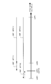
- LDP1 on the horizontal axis indicates the position before driving
- LDP2 indicates the in-focus position calculated before driving (when sensitivity is insufficient)
- LDP4 Indicates the in-focus position calculated before driving (in the case of excessive sensitivity).
- the calculated defocus amount is DEF_BFR (1).
- the true in-focus position LDP3 It is driven to the position of LDP 2 on the near side.
- the defocus shift amount with respect to the true in-focus position LDP3, that is, the defocus amount to be corrected by learning is DEF_AFT (1).
- the calculated defocus amount is DEF_BFR (2).
- the true in-focus position LDP3 It is driven to the position of LDP 4 that has passed.
- the defocus shift amount with respect to the true in-focus position LDP3, that is, the defocus amount to be corrected by learning is DEF_AFT (2).
- the amount of deviation from the true in-focus position of DEF_BFR due to excessive or insufficient sensitivity is corrected by learning.
- the imaging surface is divided into a plurality of AF areas, one of the AF areas is selected, and the focus lens 101 is focused based on focus information from the AF area.
- focus information can be acquired based on image data from focus detection pixels even from AF areas that were not selected, in this embodiment, all AF areas for which the defocus amount has been detected can be obtained.
- the conversion coefficient is learned.
- the focus lens 101 is driven to the in-focus position.
- the focus lens 101 does not necessarily approach the in-focus position after driving.
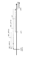
- FIG. 4 shows the case of an AF area that is far from the in-focus position after driving.
- a position LDP1 indicates a position before driving
- a position LDP3 is a position after driving, which corresponds to the in-focus position of the selected AF area.
- LD1 is a lens drive amount, and in FIG. 4, it is shown as an amount converted to a defocus amount.
- the position LDP5 is a true in-focus position of another AF area other than the selected AF area.
- DEF_BFR (3) is a defocus amount when the distance is measured before the focus lens of the focus lens 101 is driven (when the focus lens 101 is at the position LDP1).
- DEF_AFT (3) is a defocus amount when the distance is measured after the focus lens is driven to the position LDP3.
- the defocus amount DEF_COR (3) is a defocus shift amount from the true in-focus position. In the present embodiment, this defocus shift amount is corrected by learning.
- the amount to be corrected (DEF_COR (3)) can be obtained from the following equation (1).
- Amount to be corrected DEF_AFT ⁇ (DEF_BFR ⁇ lens driving amount) (1)
- the lens driving amount for moving the focus lens to the in-focus position is calculated based on the defocus amount DEF_BEF in the selected AF area.
- DEF_BEF defocus amount
- an interchangeable lens having a large backlash has a large amount of hiss removal drive, and the drive amount may be reduced on the interchangeable lens side.
- the hiss removal driving means driving for correcting driving for backlash when driving in one direction and then driving in the opposite direction.
- the reason for reducing the drive amount on the interchangeable lens side is as follows. In other words, if the lens is moved by a lens drive amount based on the defocus amount calculated on the camera body side, it passes the in-focus position (overrun occurs), and the lens is moved in the opposite direction at the next lens drive. You will have to drive. In this case, it is necessary to perform the hiss removal driving, and it takes an extra AF time to reach the in-focus position. Therefore, in order to avoid the need to perform the hiss removal driving, when calculating the lens driving amount based on the defocus amount transmitted from the main body side on the interchangeable lens side, the driving amount is reduced so that It stops before the focus. In other words, the drive amount is reduced on the interchangeable lens side, so that it is not necessary to perform hiss removal driving.
- the lens drive amount is reduced in order to prevent the hiss removal drive on the interchangeable lens side.
- the conversion coefficient is learned without feedback of the reduction amount of the lens driving amount performed on the interchangeable lens side to the camera body side, an overrun of the lens driving eventually occurs. Therefore, in the present embodiment, when control is performed on the front side on the interchangeable lens side, the drive reduction amount is transmitted to the camera body side.
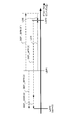
- FIG. 5 shows the defocus amount when the lens drive reduction amount is transmitted to the camera body side.
- a position LDP1 indicates a position before driving
- the defocus amount based on the two-image interval value calculated by the focus detection unit 205 at this position LDP1 is DEF_BFR (3 ′).
- the lens driving amount is reduced in order to prevent hiss removal driving
- LD2 corresponds to this lens driving reduction amount. Accordingly, the focus lens is driven from the position LDP1 by the lens driving amount LD1 so as to be in focus with respect to the selected AF, and moves to the position LDP3.
- a position LDP5 is a true in-focus position in another AF area other than the selected AF area.
- DEF_BFR (3) is a defocus amount when the distance is measured before the focus lens is driven (when it is at the position LDP1).
- DEF_AFT (3) is a defocus amount when the distance is measured after the focus lens is driven to the position LDP3.
- the defocus amount DEF_COR (3) is a defocus shift amount from the true in-focus position.
- the lens driving amount LD1 is calculated by the following equation (2).
- Lens drive amount LD1 DEF_BFR (3 ′) of selected AF area ⁇ Lens drive reduction amount LD2 (2)
- the amount to be corrected (DEF_COR (3)) is calculated by the following equation (3).
- Amount to be corrected DEF_AFT (3) ⁇ (DEF_BFR (3) ⁇ (DEF_BFR (3 ′) of selected AF area ⁇ Lens drive reduction amount LD2)) (3)
- an amount of code to be corrected is processed. If the sensitivity is insufficient, processing is performed so that the amount to be corrected becomes positive. Therefore, when the lens driving amount LD1 ⁇ 0 (the lens is driven from right to left in FIG. 5), the amount to be corrected (DEF_COR (3)). The sign of is reversed.
- the defocus amount is calculated by the following equation (4) using the AF sensitivity (conversion coefficient) and the correction amount.
- Defocus amount 2 image interval value ⁇ AF sensitivity value (design value) ⁇ (100% ⁇ correction amount) / 100% (4)
- the two-image interval value is phase difference information calculated by the focus detection unit 205
- the AF sensitivity value is a design value stored in the main body storage unit 207.
- the correction amount an optimum value is obtained by learning.
- the correction amount is set to -20% as an initial value when learning, so that the lens is not driven too much. As learning progresses, the correction amount is updated so that lens driving is completed in one time.
- the correction amount is updated. That is, the correction amount is updated except when the error amount is not abnormally large and close to the true value.
- the correction amount is updated every time the defocus amount is calculated in the learning period, and the following correction amount is set according to the amount to be corrected at that time.
- the defocus amount is calculated. , + 2% or -2%, and the value of the correction amount in the equation (4) is updated.
- the correction amount to be multiplied by the AF sensitivity value conversion coefficient
- 2% is an exemplary number and may be larger or smaller.
- the correction amount described above may be changed according to the reliability of focus detection.
- the correction amount may be + 4% or -4%. Note that 4% is an exemplary number, and may be larger or smaller in consideration of the above-mentioned 2%.
- the correction amount acquired from the learning result is stored in the main body storage unit 207 in the camera main body 200 for each lens type.
- the correction amount varies depending on the zoom state and the focus lens position, and is individually held according to these values.
- FIG. 5 is used to explain how to obtain a correction amount according to the zoom state and hold this correction amount.
- the focal length of the photographic lens 101 it is divided into 8 areas, ZMAREA [0], ZMAREA [1], ZMAREA [2], ZMAREA [3],. It is assumed that the current focal length (zoom position zmenc) belongs to the area ZMAREA [2].
- the zoom area ZMAREA [2] including the current zoom position zmenc is updated by 2%, and the zoom areas ZMAREA [1] and ZMAREA [3] adjacent to this area are updated by 1%. To do.
- correction amount of the AF sensitivity (conversion coefficient) is stored in the main body storage unit 207 in the table format as described above, but the zoom position detection unit is used by using the correction amount held for each zoom area (ZMAREA []).
- a correction amount corresponding to the current zoom value (current zmenc value) detected by 109 is calculated by linear interpolation.
- the correction amount for the current zmenc value shown in FIG. 7 is calculated from the following equation (5).
- Correction amount (learn_result [3] ⁇ learn_result [2]) ⁇ (zmenc ⁇ ZMAREA [2]) / (ZMAREA [3] ⁇ ZMAREA [2]) + learn_result [2] (5)
- learn_result [] is a correction amount that is acquired by learning in each zoom area ZMAREA [] or stored before learning.
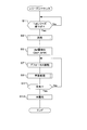
- the flowcharts shown in FIGS. 8 and 9 are executed by the CPU in the main body control unit 203 controlling each part in the camera main body 200 and the interchangeable lens 100.
- step S3 If the result of determination in step S1 is that the first release has been pressed, photometry is then performed (S3).
- the luminance of the subject is measured based on the image data read from the image sensor 201, and an exposure control value for live view display is calculated.
- a defocus amount (def amount) (DEF_BFR) is detected (S5).
- the focus detection unit 205 uses the image data from the focus detection pixels included in the image data read from the image sensor 201 in step S3, the focus detection unit 205 calculates image phase difference information (two image interval values), Output to the main body control unit 203.
- the main body control unit 203 calculates a defocus amount (def amount) using the input image phase difference information (two image interval values) and a conversion coefficient (AF sensitivity value).
- step S5 corresponds to DEF_BFR (1) or DEF_BFR (2) in FIG. 3 described above, and corresponds to DEF_BFR (3) in FIG. 4 described above. 5 corresponds to DEF_BFR (3) and DEF_BFR (3 ′).
- step S7 defocus drive (focus lens drive based on the defocus amount) is performed (S7).
- the main body control unit 203 transmits the calculated defocus amount to the lens control unit 105 via the communication unit 300, and the lens control unit 105 calculates the drive amount based on the input defocus amount and calculates the lens.
- the driving unit 103 performs defocusing driving with the photographing lens 101 toward the focal point.
- step S9 a learning process is performed (S9).
- learning is performed to optimize the conversion coefficient (AF sensitivity) described with reference to FIGS. 2 to 5 for each camera system. That is, again, the focus detection unit 205 calculates image phase difference information (two image interval values), obtains an amount to be corrected from the image phase difference information, and learns the correction amount shown in the equation (4) by learning. An amount suitable for the camera system is obtained, and the obtained correction amount is stored in the main body storage unit 207.
- the conversion coefficient (AF sensitivity) is stored in the main body storage unit 207 in advance, but the substantial conversion coefficient (AF sensitivity) is a value corrected by the correction amount. Detailed operation of this learning process will be described later with reference to FIG.
- the correction amount is learned in the learning process of step S9.
- the defocus amount calculated at this time corresponds to DEF_AFT (1) and DEF_AFT (2) in FIG. 4 corresponds to DEF_AFT (3), and in FIG. 5 described above, it corresponds to DEF_AFT (3).
- step S11 it is determined whether or not it is in focus (S11).
- focus detection is performed again by the focus detection unit 205, and it is determined whether or not the focus is achieved based on the calculated image phase difference information (two-image interval value). If the result of this determination is that it is not in focus, the process returns to step S7 to perform defocus drive and learning processing.
- the optimum correction amount for each camera system is finally obtained.
- a reduction amount is transmitted from the interchangeable lens 100 to the camera body 200 as described above with reference to FIG. 5, and correction based on this reduction amount is also performed. I am doing so. That is, the main body control unit 203 transmits the defocus amount to the lens control unit 105 via the communication terminal 300, and the lens control unit 105 calculates the movement amount of the focus lens according to the received defocus amount. The focus lens is moved, information on the amount of movement at this time (including a reduction amount reduced by a predetermined amount from the amount of movement) is transmitted to the main body control unit 203, and the conversion coefficient is corrected using the information on the amount of movement. is doing.
- step S13 If the result of determination in step S11 is in-focus, this exposure is performed (S13).
- the release button is fully pressed (2nd release pressing)
- the image data from the image sensor 201 is subjected to image processing for recording and is recorded on a recording medium (not shown) in the camera body 200.
- the sequence ends.
- the first image phase difference information is calculated using the image data from the image sensor 201 (S5), and is converted into a defocus amount using this image phase difference information.
- defocus driving is performed (S7).
- the second image phase difference information is detected by the focus detection unit, and a conversion coefficient for conversion to a defocus amount is corrected by learning based on the second image phase difference information, and stored. (S9).
- the conversion coefficient is corrected by learning, the second image phase difference information is replaced with the first image phase difference information, the second image phase difference information is detected again from the focus detection unit, and the above learning is repeated. As a result, correction can be performed so as to obtain an accurate conversion coefficient in each camera system.
- the conversion coefficient learning process in step S9 is often sufficient only when the camera system is shipped from the factory or when a new interchangeable lens 100 is attached to the camera body 200. In some cases, this may be detected after the conversion coefficient has been correctly corrected, and may be omitted in normal camera operation.
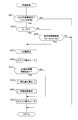
- step S9 it is first determined whether or not the posture of the camera is stable (S21).
- the main body control unit 203 determines whether or not the posture of the camera is stable.
- the reason why it is determined whether or not the posture of the camera is stable is that image phase difference information cannot be stably detected when the posture is not stable.
- the learning process flow is terminated and the original flow is restored.
- step S21 If the result of determination in step S21 is that the camera posture is stable, it is next determined whether or not it is single AF (S-AF) (S23).
- S-AF refers to an AF mode in which automatic focus adjustment is terminated when the taking lens 101 is in focus.
- continuous AF C-AF is an AF mode in which automatic focus adjustment is continued so that, for example, a moving subject follows a moving subject and continues in focus even when the photographing lens 101 is in focus.
- step S23 If the result of determination in step S23 is not S-AF, it is the case of C-AF mode or the like. In this case, it is next determined whether or not the subject moving speed is smaller than 0.2 mm / sec. Determine (S25). In the case of the C-AF mode or the like, since the subject can be continuously tracked, the moving speed of the subject can be detected. In this step, it can be determined whether or not the subject speed is slower than a predetermined speed. The moving speed of the subject is detected because the image phase difference information cannot be detected stably when the moving speed of the subject is fast. If the subject speed is higher than 0.2 mm / sec as a result of this determination, the learning process flow is terminated and the original flow is returned. In this embodiment, the predetermined speed is 0.2 mm / sec. However, the predetermined speed is not limited to this value as long as it is sufficient to detect the image phase difference information.
- the defocus amount is then detected ( S27).
- the focus detection unit 205 uses the image data from the focus detection pixels included in the image data read from the image sensor 201 after the defocus driving in step S7, and the focus detection unit 205 performs image phase difference information (two image interval values). Is calculated and output to the main body control unit 203.
- the main body control unit 203 calculates a defocus amount using the conversion coefficient stored in the main body storage unit 207 for the input image phase difference information.
- a loop for the number of AF areas is then performed in steps S29 to S37.
- the focus detection pixels arranged on the imaging surface of the imaging element 201 are grouped into a plurality of AF areas. Also, as described with reference to FIG. 4, focus information is acquired from AF areas that were not selected, and conversion coefficients are learned for all AF areas for which the defocus amount has been detected. Yes. Accordingly, in steps S29 to S37, AF areas are sequentially selected and learned, and finally, conversion coefficients are learned for all AF areas.
- step S31 it is determined whether or not the defocus detection result is reliable for the AF area selected as the learning target (S31).
- the reliability of the defocus amount for example, it is determined whether or not the contrast information of the pixel signal is smaller than a predetermined value by using the slope of the correlation value in the vicinity of the minimum value of the correlation values of the two images.
- step S31 If the result of determination in step S31 is that the defocus detection result is not reliable, the process proceeds to step S37, the AF area selected as the learning target is advanced, and the process returns to step S31.
- step S33 a correction amount is calculated in step S33 (S33).
- the image phase difference information (two image interval values) detected in step S27 is calculated, and an amount to be corrected is obtained from the image phase difference information.
- the correction amount shown in the above is learned, and a correction amount suitable for each camera system is obtained.
- the learning result is stored (S35).
- the AF area calculated in step S33 and the correction amount obtained for the AF area are stored in the main body storage unit 207.
- the correction amount is stored for each AF area, and the corrected conversion coefficient is stored.
- the conversion coefficient is corrected by performing the correction process as described with reference to FIGS. 3 to 8 and (1) to (5) (S33). Further, the reliability of the image phase difference amount is calculated, and the conversion coefficient is corrected based on this reliability (S31).
- the main body control unit 203 functioning as a focus adjustment unit corrects the conversion coefficient based on the reliability of the calculated image phase difference amount (S31).
- the main body control unit 203 functioning as a focus adjustment unit corrects a plurality of conversion coefficients corresponding to a plurality of ranging areas based on image phase difference information corresponding to a plurality of ranging areas (AF areas). (S29 to S37). Further, as described with reference to FIG. 5, the conversion coefficient is corrected based on the focal length of the photographing optical system during learning. Further, the conversion coefficient is corrected based on the position of the focus lens of the photographing lens 101.
- the image phase difference information is detected based on the light beam that has passed through the photographing optical system including the focus lens (S5 in FIG. 8), and the image phase difference information is converted into the image phase difference information.
- the image phase difference information is converted into a defocus amount by a conversion coefficient for converting into a focus amount (S5), and focus adjustment is performed by moving the focus lens based on the defocus amount (S7).
- the first image phase difference information is detected (S5), the first image phase difference information is converted into a defocus amount by a conversion coefficient (S5), and the focus lens is moved based on the defocus amount.
- second image phase difference information is detected (S27 in FIG. 9), and the conversion coefficient is corrected based on the second image phase difference information (S33). For this reason, even if there are variations in individual focus adjustment devices, it is possible to perform correction so as to obtain an accurate conversion coefficient by learning.
- the imaging device 201 includes a focus detection pixel that receives a light beam obtained by imaging a light beam that has passed through the photographing lens 101 and outputting an image signal, and dividing the light beam into pupils.
- the focus detection unit 205 detects image phase difference information based on the output of focus detection pixels output from the image sensor 201. That is, since the image sensor 201 itself has focus detection pixels, it is not necessary to arrange a special optical system for pupil division, and the camera can be downsized.
- the focus detection unit 203 calculates the reliability indicating the reliability of the image phase difference information (S31 in FIG. 9), and the main body control unit 203 that functions as the focus adjustment unit includes:
- the conversion coefficient is corrected based on this reliability. That is, the conversion coefficient is corrected by learning only when there is reliability. For this reason, a highly reliable conversion coefficient can be obtained.
- the focus detection unit 205 has a plurality of ranging areas in the field of view of the photographing optical system, detects image phase difference information corresponding to each ranging area, and
- the main body control unit 203 functioning as an adjustment unit corrects a plurality of conversion coefficients corresponding to the plurality of ranging areas based on the image phase difference information corresponding to the plurality of ranging areas (S29 to S37 in FIG. 9).
- a plurality of conversion coefficients corresponding to a plurality of distance measurement areas can be corrected. Therefore, a plurality of conversion coefficients can be corrected in a short time.
- the photographing optical system is an optical system having a variable focal length, and includes a zoom position detection unit 109 (focal length detection unit) that detects the focal length of the photographing optical system.
- the focus adjustment unit 205 corrects the conversion coefficient based on the focal length of the photographing optical system. For this reason, even if the interchangeable lens is a zoom lens, it can be corrected so as to have an accurate conversion coefficient corresponding to each variation.
- the main body control unit 203 that functions as a focus adjustment unit corrects the conversion coefficient based on the position of the focus lens. For this reason, even if the conversion coefficient differs depending on the position of the focus lens, it is possible to correct the conversion coefficient so as to correspond to each variation.
- the main body control unit 203 that functions as focus adjustment transmits the defocus amount to the lens control unit 105 via the lens communication unit
- the lens control unit 105 includes the main body control unit.
- the amount of movement of the focus lens is calculated according to the amount of defocus transmitted from 203, the focus lens is moved, and information related to the amount of movement is transmitted to the camera body 203 via the lens communication unit.
- the main body 203 corrects the conversion coefficient based on information related to the movement amount (see FIG. 5). In this way, since the conversion coefficient is corrected in consideration of the movement amount of the focus lens in the lens control unit 103, the defocus amount calculated in the main body control unit 203 and the lens drive amount that does not correspond one-to-one. Even in such a case, it is possible to correct so as to obtain an accurate conversion coefficient corresponding to each variation.
- the lens control unit 103 calculates the movement amount of the focus lens according to the defocus amount transmitted from the main body control unit 203, and reduces the movement amount by a predetermined amount to focus.
- the lens is moved, and the decreased movement amount is transmitted to the main body control unit 203 via the lens communication unit, and the main body control unit 203 corrects the conversion coefficient based on the decreased movement amount (see FIG. 5).
- the conversion coefficient is corrected in consideration of the amount of movement of the focus lens reduced by the lens control unit 103, a lens that does not have a one-to-one correspondence with the defocus amount calculated by the main body control unit 203. Even in the case of the drive amount, it is possible to correct it so as to obtain an accurate conversion coefficient corresponding to each variation.
- the output of the focus detection pixels arranged in the image sensor 201 is used to acquire image phase difference information.
- the present invention is not limited to this, and the light beam may be divided by a half mirror or the like, and the divided light beam may be divided into pupils to receive the light beam.
- the camera system including the interchangeable lens 100 that is detachable from the camera body 200 has been described.
- the present invention can also be applied to other camera systems.
- the digital camera is used as the photographing device.
- the camera may be a digital single-lens reflex camera or a compact digital camera, and may be used for moving images such as video cameras and movie cameras. It may be a camera, or may be a camera built in a mobile phone, a smart phone, a personal digital assistant (PDA), a game machine, or the like.
- PDA personal digital assistant
- the present invention can be applied to any device that adjusts the focus of an optical lens based on image phase difference information.
- control mainly described in the flowchart is often settable by a program and may be stored in a recording medium or a recording unit.
- the recording method for the recording medium and the recording unit may be recorded at the time of product shipment, may be a distributed recording medium, or may be downloaded via the Internet.
- the present invention is not limited to the above-described embodiment as it is, and can be embodied by modifying the constituent elements without departing from the scope of the invention in the implementation stage.
- various inventions can be formed by appropriately combining a plurality of components disclosed in the embodiment. For example, you may delete some components of all the components shown by embodiment.
- constituent elements over different embodiments may be appropriately combined.
- DESCRIPTION OF SYMBOLS 100 ... Interchangeable lens, 101a, 101b, 101 ... Shooting lens, 103 ... Lens drive part, 105 ... Lens control part, 107 ... Lens storage part, 109 ... Zoom position detection part , 111... Zoom ring, 200... Camera body, 201... Image sensor, 203... Body control unit, 205. Gyro, 300 ... Communication terminal
Landscapes
- Physics & Mathematics (AREA)
- General Physics & Mathematics (AREA)
- Optics & Photonics (AREA)
- Engineering & Computer Science (AREA)
- Multimedia (AREA)
- Signal Processing (AREA)
- Studio Devices (AREA)
- Focusing (AREA)
- Automatic Focus Adjustment (AREA)
Abstract
個々の焦点調節装置において正確な変換係数となるように補正が可能な焦点調節装置、カメラシステム、および焦点調節方法を提供する。撮像素子201の焦点検出用画素からの画像データに基づいて、2像間隔値(像位相差情報)を算出し、本体制御部203内のCPUはデフォーカス量yを算出し(S5)、レンズ駆動量を算出し、レンズ駆動を行う(S7)。この後、学習アルゴリズムにより、デフォーカス量の算出のための変換係数を補正する(S9)。
Description
本発明は、位相差AF法による焦点調節を行う焦点調節装置、カメラシステム、及び焦点調節方法に関する。
従来からカメラシステム等における焦点調節として位相差AF法が用いられている。この位相差AF法では、2像間隔値(像位相差情報ともいう)を求め、この2像間隔値を変換係数(AF感度ともいう)を用いてデフォーカス量に変換している。この変換係数は、いわゆる像面位相差AF法の場合には、撮像素子の固体ばらつきや、撮影レンズの固体ばらつきによって変動する。撮像素子の固体ばらつきはとして、瞳分割用のオンチップマイクロレンズの出来栄えによるばらつきの影響が大きい。また、撮影レンズの固体ばらつきとしては、絞りの開口径の出来栄えばらつきによる影響が大きい。このような変換係数を補正する撮像装置が、特許文献1に記載されている。この特許文献1においては、時間経過とともに複数回取得した焦点検出画素の画素データを加算して画像データとして2像間隔値を求めてデフォーカス量に変換する際に、この時間経過中の撮影レンズの光学的な変化に対応するために変換係数を補正してデフォーカス量を算出することが開示されている。
上述の特許文献1には光学系の時間的な変化に関する変換係数を補正することは開示されている。しかしながら、撮像素子や交換レンズの個体ばらつきに起因する変換係数のばらつきを補正することについては開示されていない。変換係数のばらつきを補正するにあたって、撮像素子の個体ばらつきの影響を吸収するために、調整を行うことは可能だが、交換レンズの個体ばらつき分を調整することは、非常に困難である。また、撮像素子の個体ばらつきと交換レンズの個体ばらつきが相互に影響し合うばらつき成分についても調整することは困難である。例えば、図2は、横軸に2像間隔、縦軸にデフォーカス量をとり、L1~L3は、変換係数曲線であり、撮像素子と交換レンズの個体ばらつきに起因してばらつくものとする。今、2像間隔値がXであった場合の真の変換係数曲線をL3とし、現在、使用している変換係数曲線がL1とすると、デフォーカス量はyとなり、真のデフォーカス量y’よりも小さな値を算出してしまう。この結果、レンズ駆動が不足状態となり、再度、2像間隔値の検出を行い、レンズ駆動(LDともいう)を行う必要がある。
したがって、レンズ駆動回数が多くなり、AF時間が長くなってしまう。また、AF感度がズレている場合、コンティニュアスAF中や連写AF中のピントズレ量を正確に検出できないため、動体予測性能が劣化してしまう。
本発明は、このような事情を鑑みてなされたものであり、個々の焦点調節装置において正確な変換係数となるように補正が可能な焦点調節装置、カメラシステム、および焦点調節方法を提供することを目的とする。
本発明の第1の態様に係る焦点調節装置は、フォーカスレンズを含む撮影光学系を通過した光束に基づいて像位相差情報を検出する焦点検出部と、上記像位相差情報をデフォーカス量に変換する変換係数を記憶する記憶部と、上記変換係数により上記像位相差情報をデフォーカス量に変換し、該デフォーカス量に基づいて上記フォーカスレンズを移動させて焦点調節を行う焦点調節部と、を具備し、上記焦点調節部は、上記焦点検出部が検出した第1の像位相差情報を上記変換係数によりデフォーカス量に変換し、該デフォーカス量に基づいて上記フォーカスレンズを移動させた後に、上記焦点検出部により第2の像位相差情報を検出させ、上記第2の像位相差情報に基づいて上記変換係数を補正して上記記憶部に記憶させる。
本発明の第2の態様に係るカメラシステムは、撮影光学系を有する交換レンズと、該交換レンズを装着可能なカメラ本体とを有するカメラシステムにおいて、上記交換レンズは、上記撮影光学系に含まれるフォーカスレンズの移動を制御するレンズ制御部と、上記交換レンズに固有の識別情報を記憶するレンズ記憶部と、上記カメラ本体と通信するレンズ通信部と、を有し、上記カメラ本体は、上記撮影光学系を通過した光束に基づいて像位相差情報を検出する焦点検出部と、上記像位相差情報をデフォーカス量に変換する変換係数を、上記交換レンズの識別情報に対応して記憶する本体記憶部と、上記レンズ通信部を介して上記レンズ記憶部より取得された上記交換レンズの識別情報基づいて、上記本体記憶部に記憶された変換係数を選択し、変換係数により上記像位相差情報をデフォーカス量に変換し、該デフォーカス量に基づいて上記レンズ制御部により上記フォーカスレンズを移動させて焦点調節を行う焦点調節部と、を具備し、上記焦点調節部は、上記焦点検出部が検出した第1の像位相差情報を上記変換係数によりデフォーカス量に変換し、該デフォーカス量に基づいて上記フォーカスレンズを移動させた後に、上記焦点検出部により第2の像位相差情報を検出させ、上記第2の像位相差情報に基づいて上記変換係数を補正して上記本体記憶部に記憶させる。
本発明の第3の態様に係る焦点調節方法は、本発明の第3の態様に係わる焦点調節方法は、フォーカスレンズを含む撮影光学系を通過した光束に基づいて像位相差情報を検出し、上記像位相差情報をデフォーカス量に変換する変換係数により上記像位相差情報をデフォーカス量に変換し、該デフォーカス量に基づいて上記フォーカスレンズを移動させて焦点調節を行う焦点調節装置の焦点調節方法において、第1の像位相差情報を検出し、上記第1の像位相差情報を上記変換係数によりデフォーカス量に変換し、該デフォーカス量に基づいて上記フォーカスレンズを移動させた後に、第2の像位相差情報を検出し、上記第2の像位相差情報に基づいて上記変換係数を補正する。
本発明によれば、個々の焦点調節装置において正確な変換係数となるように補正が可能な焦点調節装置、カメラシステム、および焦点調節方法を提供することができる。
以下、図面に従って本発明を適用したカメラシステムを用いて好ましい実施形態について説明する。図1は、本発明の一実施形態に係るカメラシステムの主として電気的構成を示すブロック図である。このカメラシステムは、焦点距離を可変な撮影光学系を有する交換レンズ100と、該交換レンズを着脱可能なカメラ本体200を有する。なお、本実施形態においては、交換レンズ100とカメラ本体200を着脱可能としているが、これに限らず、撮影レンズとカメラ本体が一体に構成されたカメラシステムであってもよい。
交換レンズ100内には、撮影光学系を構成する撮影レンズ101a、101b(これらの撮影レンズを総称する際には、101と称す)が配置されている。撮影レンズ101は、フォーカスレンズを含む。この撮影レンズ101は、レンズ駆動部103によって、光軸O方向に沿って、それぞれ移動可能である。このレンズ駆動部103によって、撮影レンズ101a、101bの位置が変更される。
交換レンズ100の外周には、ズーム環111が回動自在に配置されており、ユーザがズーム環111を手動で回動させると、撮影レンズ101a、101bの位置が変更されることによって、焦点距離が変更される。
レンズ駆動部103は、ステッピングモータやDCモータ等のアクチュエータを有し、このアクチュエータによって撮影レンズ101a、101bの位置を移動させる。レンズ駆動部103は、レンズ制御部105に接続され、このレンズ制御部105によってレンズ駆動部103が制御される。レンズ制御部105は、CPUやASIC等の回路を有し、レンズ記憶部107に記憶されたプログラムに従って交換レンズ100の制御を行う。また、レンズ制御部105は、レンズ駆動103を介して撮影レンズ101(撮影光学系)に含まれるフォーカスレンズの移動を制御する。レンズ駆動部103は、アクチュエータの駆動量等に基づいてフォーカスレンズ位置を検出し、レンズ制御部105に出力する。この交換レンズ100の制御にあたっては、通信端子300を介してカメラ本体200内の本体制御部203と通信を行い、カメラ本体200からの制御命令に応じた制御を行う。レンズ制御部105は、カメラ本体200と通信するレンズ通信部としての機能も果たす。
レンズ記憶部107は、不揮発性の書き換え可能なメモリを含み、レンズ制御部105に接続されている。記憶部107には、前述の制御用のプログラムの他、交換レンズ100の各種調整値が記憶されている。また、レンズ記憶部107は、交換レンズ100に固有の識別情報を記憶している。
ズーム位置検出部109は、レンズ制御部105に接続され、撮影レンズ101a、101bの位置に基づいて、撮影光学系の焦点距離に応じたズーム位置を検出し、レンズ制御部105に出力する。レンズ制御部105は、この入力したズーム位置をレンズ通信部を介してカメラ本体200に送信する。なお、本実施形態においては、レンズ駆動部103によってフォーカスレンズ位置を検出しているが、ズーム位置検出部109が、フォーカスレンズ位置を検出し、レンズ制御部105に出力するようにしてもよい。
交換レンズ100を装着可能なカメラ本体200内には、撮像素子201、本体制御部203、焦点検出部205、本体記憶部207、ジャイロ209が配置されている。撮像素子201は、撮影レンズ101の光軸O上であって、被写体像が形成される位置に配置され、被写体像を光電変換し、画像データを本体制御部203に出力する。また、撮像素子201は、画素面に撮像用画素の他に、撮影光学系を通過した光束を瞳分割した光束を受光し像位相差情報を検出するための焦点検出用画素が配置されている。
焦点検出部205は、フォーカスレンズを含む撮影光学系を通過した光束に基づいて像位相差情報を検出する。具体的には、撮像素子201の焦点検出用画素は、撮影光学系を通過した光束を瞳分割した光束を受光し、この光束に基づいて焦点検出信号を出力する。焦点検出部205は、撮像素子201から焦点検出信号を入力し、像位相差情報(2像間隔値)を算出し、本体制御部203に出力する。
また、焦点検出部205は、像位相差情報の信頼性を示す信頼度を算出する。信頼度としては、画素信号のコントラスト情報が所定値より小さいか否か、2像の相関値の最小値付近における2像の相関値の傾き等を用いて判定する。また、焦点検出部205は、撮影光学系の視野内に複数の測距エリアを有し、それぞれの測距エリアに対応する像位相差情報を検出する。
本体記憶部207は、書き換え可能な不揮発性メモリを含み、本体制御部203に接続され、本体制御部203の制御用プログラム、また位相差情報をデフォーカス量に変換する変換係数を、交換レンズ100の識別情報に対応して記憶する。
ジャイロ209は、カメラ本体200に加えられた振動等を検出するためのセンサであり、検知信号は本体制御部203に出力される。本体制御部203は、ジャイロ209からの検知信号に基づいてカメラの姿勢が安定しているか否かを判定できる。なお、カメラの姿勢が安定しているか否かを判定できれば、ジャイロに限らず、他のセンサでもよい。
本体制御部203は、CPU等の制御部を有し、本体記憶部207に記憶されたプログラムに従ってカメラ本体200の制御を行うと共に、レンズ制御部105と通信を行って、カメラシステム全体の制御を行う。本体制御部203とレンズ制御部105は、通信端子300を介して、制御コマンドおよびズーム位置等のレンズデータのやり取りを行う。
また、本体制御部203は、本体記憶部207に記憶された変換係数を用いて像位相差情報をデフォーカス量に変換し、このデフォーカス量に基づいて撮影光学系のフォーカスレンズを移動させて焦点調節を行う焦点調節部としての機能を果たす。
また、この焦点調節部は、レンズ通信部(レンズ制御部105がその機能を果たす)を介してレンズ記憶部107より取得された交換レンズ100の識別情報基づいて、本体記憶部207に記憶された変換係数を選択し、変換係数により像位相差情報をデフォーカス量に変換し、このデフォーカス量に基づいてレンズ制御部105により撮影レンズ101内のフォーカスレンズを移動させて焦点調節を行う。また、この焦点調節部は、フォーカスレンズ位置検出部(ズームレンズ位置検出109がその機能を果たす)から通信部を介してフォーカスレンズの位置を取得し、フォーカスレンズの位置に基づいて変換係数を補正する。
また、この焦点調節部は、焦点検出部205が検出した第1の像位相差情報を変換係数によりデフォーカス量に変換し、このデフォーカス量に基づいてフォーカスレンズを移動させた後に、焦点検出部205により第2の像位相差情報を検出させ、第2の像位相差情報に基づいて変換係数を補正して本体記憶部207に記憶させる。すなわち、本実施形態においては、個々のカメラシステムにばらつきがあっても、変換係数が個々の交換レンズ100とカメラ本体200に適した値となるように学習機能を用いて補正している。この学習機能については、図9および図10を用いて後述する。
次に、図2ないし図7を用いて、学習による変換係数(AF感度)の補正の仕方について説明する。図2において、横軸は焦点検出部205によって検出される2像間隔値を示し、縦軸は2像間隔値に変換係数を乗算して得られるデフォーカス量を示す。また、折れ曲がり曲線L1~L3は変換係数曲線(AF感度曲線)であり、このうち、一例として変換係数曲線L1は変換係数の下限値であり、変換係数曲線L2は変換係数の中間値であり、変換係数曲線L3は変換係数曲線の上限値であるとする。下限値と上限値は、ばらつきの限界値であり、変換係数曲線L1と変換係数曲線L3は、想定される変換係数の下限値と上限値であり予め工場出荷段階でレンズ記憶部107に記憶しておく。この変換係数曲線L1、L3を用いて、本実施形態においては、学習により、真の変換係数曲線を求める。
図2に示す例において、今、焦点検出部205から2像間隔値としてxが算出されたとする。また、このカメラシステムにおける真の変換係数は上限値である変換係数曲線L3とし、変換係数の学習にあたって、下限値である変換係数曲線L1から始めるとする。2像間隔値xの場合、変換係数曲線L1を用いてデフォーカス量を求めるとyとなり、この場合の真の変換係数L3を用いた場合のデフォーカス量はy’となる。この場合には、デフォーカス量が真の値(y’)と比較して小さいことから、フォーカスレンズの駆動量が小さく、駆動不足となる。このため、再度、2像間隔値を求め、これからデフォーカス量、駆動量を求めてレンズ駆動することから、レンズ駆動回数が多くなりAF時間が長くなる。
このため、本実施形態においては、実使用時におけるデフォーカス量に基づくフォーカスレンズの駆動前後のデフォーカス量検出結果の差分を算出することで、AF感度(変換係数)の過不足を検出し、ばらつきを考慮した真のAF感度(変換係数)を記憶し、以後、記憶されたAF感度を用いてデフォーカス量を使用するようにしている。したがって、本実施形態においては、初めて交換レンズカメラシステムを使用する場合や、今まで使用したことのない交換レンズを装着した場合には、真のAF感度(変換係数)を検出するための時間を要する。しかし、真のAF感度(変換係数)を記憶した後は、迅速にAF制御を行うことが可能となる。
次に、図3を用いて、AF感度の過不足の検出について説明する。図3において、横軸のLDP1は駆動前位置を示し、LDP2は駆動前に算出した合焦位置(感度不足の場合)を示し、LDP3は真の合焦位置(def=0)を示し、LDP4は駆動前に算出した合焦位置(感度過多の場合)を示す。
したがって、駆動前に算出した合焦位置が感度不足の場合には、算出したデフォーカス量はDEF_BFR(1)であり、このデフォーカス量に基づいてフォーカスレンズ101を駆動すると真の合焦位置LDP3より手前のLDP2の位置に駆動される。真の合焦位置LDP3とのデフォーカスずれ量、すなわち学習によって補正したいデフォーカス量はDEF_AFT(1)となる。
また、駆動前に算出した合焦位置が感度過多の場合には、算出したデフォーカス量はDEF_BFR(2)であり、このデフォーカス量に基づいてフォーカスレンズ101を駆動すると真の合焦位置LDP3を通り過ぎたLDP4の位置に駆動される。真の合焦位置LDP3とのデフォーカスずれ量、すなわち学習によって補正したいデフォーカス量はDEF_AFT(2)となる。
本実施形態においては、感度の過不足に起因するDEF_BFRの真の合焦位置からのズレ量を学習によって補正するようにしている。
次に、図4を用いて、複数のAFエリア(測距エリア)を設けた場合の変換係数の学習について説明する。通常、測距にあたっては、撮像面を複数のAFエリアに分け、いずれかAFエリアを選択し、このAFエリアからの焦点情報に基づいてフォーカスレンズ101のピント合わせを行う。しかし、選択しなかったAFエリアからも焦点検出用画素からの画像データに基づいて焦点情報を取得することができることから、本実施形態においては、デフォーカス量を検出できた全てのAFエリアに対して、変換係数の学習を行うようにしている。
選択されたAFエリアに対しては、フォーカスレンズ101を合焦位置に駆動されるが、選択されなかったAFエリアでは、フォーカスレンズ101の駆動後に合焦位置に近づくとは限らない。図4の例は、駆動後に合焦位置から離れたAFエリアの場合を示す。
図4において、位置LDP1は駆動前の位置を示し、位置LDP3は駆動後位置であり、選択されたAFエリアの合焦位置に対応する位置である。LD1はレンズ駆動量であり、図4ではデフォーカス量に換算した量で示している。位置LDP5は選択されたAFエリア以外の別のAFエリアの真の合焦位置である。DEF_BFR(3)は、フォーカスレンズ101のフォーカスレンズの駆動前(位置LDP1にある時)に測距したときのデフォーカス量である。また、DEF_AFT(3)は、フォーカスレンズが位置LDP3に駆動された後に、測距したときのデフォーカス量である。デフォーカス量DEF_COR(3)は、真の合焦位置とのデフォーカスずれ量である。本実施形態においては、このデフォーカスずれ量を学習によって補正する。
補正したい量(DEF_COR(3))は、下記(1)式から求めることができる。
補正したい量=DEF_AFT-(DEF_BFR-レンズ駆動量) ・・・(1)
補正したい量=DEF_AFT-(DEF_BFR-レンズ駆動量) ・・・(1)
なお、図3においては、DEF_BFR-レンズ駆動量=0であることから、補正したい量=DEF_AFTとして表わすことができる。ここで、以下に示すように、補正したい量の符号の加工を行う。感度不足の場合、補正したい量が正になるように処理するため、レンズ駆動量LD1<0(図4にて右から左へレンズ駆動する)の場合は、補正したい量(DEF_COR(3))の符号を逆転させる。
次に、図5を用いて、交換レンズ側でレンズ駆動量を修正した場合の変換係数補正について説明する。合焦位置にフォーカスレンズを移動させるためのレンズ駆動量は、選択されたAFエリアにおけるデフォーカス量DEF_BEFに基づいて算出する。しかし、バックラッシュの大きい交換レンズにおいては、ヒス取り駆動量が多く、交換レンズ側で駆動量を削減する場合がある。なお、ヒス取り駆動は、一方向に駆動した後、逆方向に駆動する場合には、バックラッシュ分の駆動を補正するための駆動をいう。
この交換レンズ側で駆動量を削減するのは、以下の理由による。すなわち、カメラ本体側で算出されたデフォーカス量に基づくレンズ駆動量でレンズを移動させると、合焦位置を通り過ぎてしまい(オーバランの発生)、次回のレンズ駆動の際には、逆方向にレンズ駆動しなければならなくなる。この場合、ヒス取り駆動を行わなければならず、合焦位置に達するまでのAF時間が余計にかかってしまう。そこで、ヒス取り駆動を行わなくても済むように、交換レンズ側で、本体側から送信されてきたデフォーカス量に基づいてレンズ駆動量を算出する際に、駆動量を小さくなるようにし、合焦点の手前で停止するようにしている。すなわち、交換レンズ側で駆動量を削減し、ヒス取り駆動を行わないで済むようにしている。
このように、交換レンズ側でヒス取り駆動を防止するために、レンズ駆動量を削減している。しかし、交換レンズ側で行ったレンズ駆動量の削減量をカメラ本体側にフィードバックがなされないまま、変換係数の学習を行うと、結局、レンズ駆動のオーバランが発生してしまう。そこで、本実施形態においては、交換レンズ側で、手前に駆動する制御を行う場合には、駆動削減量をカメラ本体側に送信するようにする。
図5に、レンズ駆動削減量をカメラ本体側に送信する場合のデフォーカス量を示す。図5において、位置LDP1は駆動前の位置を示し、この位置LDP1において焦点検出部205によって算出された2像間隔値に基づくデフォーカス量がDEF_BFR(3’)である。しかし、前述したように、レンズ鏡筒側では、ヒス取り駆動を防止するために、レンズ駆動量を削減しており、LD2はこのレンズ駆動削減量に相当する。したがって、選択されたAFに対して合焦となるように、フォーカスレンズは位置LDP1からレンズ駆動量LD1だけ駆動され、位置LDP3に移動する。
図5において、位置LDP5は選択されたAFエリア以外の別のAFエリアの真の合焦位置である。DEF_BFR(3)は、フォーカスレンズの駆動前(位置LDP1にある時)に測距したときのデフォーカス量である。また、DEF_AFT(3)は、フォーカスレンズが位置LDP3に駆動された後に、測距したときのデフォーカス量である。デフォーカス量DEF_COR(3)は、真の合焦位置とのデフォーカスずれ量である。
このように、図5に示す場合には、レンズ駆動量LD1は、下記(2)式で算出される。
レンズ駆動量LD1=選択AFエリアのDEF_BFR(3’)-レンズ駆動削減量LD2 ・・・(2)
レンズ駆動量LD1=選択AFエリアのDEF_BFR(3’)-レンズ駆動削減量LD2 ・・・(2)
また、補正したい量(DEF_COR(3))は、下記(3)式で算出される。
補正したい量=DEF_AFT(3)-(DEF_BFR(3)-(選択AFエリアのDEF_BFR(3’)-レンズ駆動削減量LD2) ・・・(3)
ここで、以下に示すように、補正したい量の符号の加工を行う。感度不足の場合、補正したい量が正になるように処理するため、レンズ駆動量LD1<0(図5にて右から左へレンズ駆動する)の場合は、補正したい量(DEF_COR(3))の符号を逆転させる。
補正したい量=DEF_AFT(3)-(DEF_BFR(3)-(選択AFエリアのDEF_BFR(3’)-レンズ駆動削減量LD2) ・・・(3)
ここで、以下に示すように、補正したい量の符号の加工を行う。感度不足の場合、補正したい量が正になるように処理するため、レンズ駆動量LD1<0(図5にて右から左へレンズ駆動する)の場合は、補正したい量(DEF_COR(3))の符号を逆転させる。
次に、補正量の算出について説明する。まず、デフォーカス量は、AF感度(変換係数)と補正量を用いて、下記(4)式で算出される。
デフォーカス量=2像間隔値×AF感度値(設計値)×(100%-補正量)/100% ・・・(4)
ここで、2像間隔値は焦点検出部205によって算出される位相差情報であり、またAF感度値は本体記憶部207に記憶されている設計値である。補正量は、学習によって、最適な値を求める。
デフォーカス量=2像間隔値×AF感度値(設計値)×(100%-補正量)/100% ・・・(4)
ここで、2像間隔値は焦点検出部205によって算出される位相差情報であり、またAF感度値は本体記憶部207に記憶されている設計値である。補正量は、学習によって、最適な値を求める。
補正量は、学習する際に、初期値として-20%としておき、レンズ駆動が行き過ぎないようにする。学習が進むにつれ、補正量を更新し、レンズ駆動を1回で完了するようにする。
また、上述した補正したい量が、「上限値>|補正したい量|>下限値」の場合には、補正量の更新を行う。すなわち、補正量の更新は、異常に誤差量が大きくなく、かつ、真の値に近い場合を除いて行うことにする。補正量の更新は、学習期間において、デフォーカス量を算出するたびに行い、その時の補正したい量に応じて、下記のような補正量とする。
「補正したい量>0」のとき、補正量+=2%
「補正したい量<0」のとき、補正量-=2%
「補正したい量>0」のとき、補正量+=2%
「補正したい量<0」のとき、補正量-=2%
したがって、補正したい量、すなわち、図3に示す例では、DEF_AFT(2)、図4及び図5に示す例では、DEF_COR(3)が0より大きい場合には、デフォーカス量を算出した際に、+2%または-2%ずつ、(4)式における補正量の値を更新していく。これによって、AF感度値(変換係数)に乗算する補正量が更新され、次第に真の合焦位置に駆動することが可能となる。なお、2%は例示的な数字であり、これよりも大きくても小さくてもよい。
なお、上述の補正量は、焦点検出の信頼度に応じて変更するようにしてもよい。例えば、DEF_AFTの検出時の測距エリア内の像のコントラスト量≧所定の閾値、かつDEF_AFTの検出時の2像の相関値が最小値付近の相関値の傾き≧所定の閾値の時には、信頼度が高いとみなして補正量+4%、-4%としてもよい。なお、4%は例示的な数字であり、上述の2%を考慮して、これよりも大きくても小さくてもよい。
上述の学習の結果によって取得した補正量は、レンズ種別毎に、カメラ本体200内の本体記憶部207に記憶する。また、補正量は、ズーム状態およびフォーカスレンズ位置によって異なり、これらの値に応じて個別に保持する。
図5を用いて、ズーム状態に応じて補正量を求め、この補正量を保持することについて説明する。本実施形態においては、撮影レンズ101の焦点距離に応じて、ZMAREA[0],ZMAREA[1],ZMAREA[2],ZMAREA[3],・・・の8領域に分けている。現在の焦点距離(ズーム位置zmenc)が領域ZMAREA[2]に属しているとする。ズーム状態に応じて、現在のズーム位置zmencを含むズーム領域ZMAREA[2]は2%ずつ更新し、またこの領域に隣接するズーム領域ZMAREA[1]とZMAREA[3]については、1%ずつ更新する。
また、補正量は、フォーカスレンズ位置やデフォーカス領域に応じて異なることから、同様に、これらの領域毎に補正量を保持する。したがって、補正量は、レンズ種別毎、ズーム領域毎、フォーカスレンズ位置毎、デフォーカス領域毎に、それぞれ補正量を学習によって求め、テーブル形式で本体記憶部207に保持する。例えば、レンズの種別が20種類、ズーム領域が20領域、フォーカスレンズ位置が20箇所、デフォーカス領域が20箇所あると、20×20×20×20=16000通りの補正量となる。
また、AF感度(変換係数)の補正量は、上述したようにテーブル形式で本体記憶部207に記憶するが、ズーム領域(ZMAREA[])毎に保持する補正量を用いて、ズーム位置検出部109によって検出された現在ズーム値(現zmenc値)に応じた補正量を、直線補間により算出する。図7に示す現zmenc値における補正量は、下記(5)式から算出する。
補正量=(learn_result[3]-learn_result[2])×(zmenc-ZMAREA[2])/(ZMAREA[3]-ZMAREA[2])+learn_result[2] ・・・(5)
ここで、learn_result[]は、各ズーム領域ZMAREA[]において学習で取得した、または学習する前の記憶された補正量である。
補正量=(learn_result[3]-learn_result[2])×(zmenc-ZMAREA[2])/(ZMAREA[3]-ZMAREA[2])+learn_result[2] ・・・(5)
ここで、learn_result[]は、各ズーム領域ZMAREA[]において学習で取得した、または学習する前の記憶された補正量である。
次に、図8および図9に示すフローチャートを用いて、本実施形態における主として学習の動作について説明する。図8および図9に示すフローチャートは本体制御部203内のCPUがカメラ本体200内および交換レンズ100内の各部を制御することにより実行する。
図8に示すフローに入ると、まず、1stレリーズの押下げがなされたか否かを判定する(S1)。ここでは、図示しないレリーズ釦の半押し操作によって連動する1stレリーズスイッチの操作状態が本体制御部203に入力され、判定される。
ステップS1における判定の結果、1stレリーズ押下げがなされた場合には、次に、測光を行う(S3)。ここでは、撮像素子201から読み出した画像データに基づいて、被写体の輝度を測定し、ライブビュー表示のための露出制御値等を算出する。
ステップS3において測光を行うと、次に、デフォーカス量(def量)(DEF_BFR)の検出を行う(S5)。ここでは、ステップS3において撮像素子201から読み出した画像データの中に含まれる焦点検出用画素からの画像データを用いて、焦点検出部205が像位相差情報(2像間隔値)を算出し、本体制御部203に出力する。本体制御部203は、入力した像位相差情報(2像間隔値)と変換係数(AF感度値)を用いて、デフォーカス量(def量)を算出する。
また、ステップS5において算出されるデフォーカス量は、前述した図3においては、DEF_BFR(1)、またはDEF_BFR(2)に相当し、前述した図4においては、DEF_BFR(3)に相当し、前述した図5においては、DEF_BFR(3)およびDEF_BFR(3’)に相当する。
ステップS5においてデフォーカス量を検出すると、デフォーカス駆動(デフォーカス量に基づくフォーカスレンズ駆動)を行う(S7)。ここでは、本体制御部203は、算出したデフォーカス量を、通信部300を介してレンズ制御部105に送信し、レンズ制御部105は入力したデフォーカス量に基づいて、駆動量を算出しレンズ駆動部103によって撮影レンズ101を合焦点に向けデフォーカス駆動を行う。
ステップS7においてデフォーカス駆動を行うと、次に、学習処理を行う(S9)。ここでは、図2ないし図5を用いて説明した変換係数(AF感度)を個々のカメラシステムに最適にするための学習を行う。すなわち、再度、焦点検出部205は像位相差情報(2像間隔値)を算出し、この像位相差情報から補正したい量を求め、これから(4)式に示した補正量を学習によって、個々のカメラシステムに相応しい量を求め、この求めた補正量を本体記憶部207に記憶する。変換係数(AF感度)は、予め本体記憶部207に記憶されているが、実質的な変換係数(AF感度)は補正量によって補正された値である。この学習処理の詳しい動作については、図9を用いて後述する。
なお、ステップS9の学習処理において補正量の学習を行うが、この際に算出されるデフォーカス量は、前述した図3においては、DEF_AFT(1)、DEF_AFT(2)に相当し、前述した図4においては、DEF_AFT(3)に相当し、前述した図5においては、DEF_AFT(3)に相当する。
学習処理を行うと、合焦か否かを判定する(S11)。ここでは、ステップS7におけるデフォーカス駆動後に、再度、焦点検出部205によって焦点検出を行い、算出された像位相差情報(2像間隔値)に基づいて合焦か否かを判定する。この判定の結果、合焦でなかった場合には、ステップS7に戻り、デフォーカス駆動、学習処理を行う。デフォーカス駆動を行う毎に補正量の学習を繰り返すことにより、最終的には個々のカメラシステムに最適な補正量が求まる。
なお、デフォーカス駆動を行い、学習処理を行う際には、図5を用いて前述したように、交換レンズ100からカメラ本体200に対して削減量を送信し、この削減量に基づく補正も行うようにしている。すなわち、本体制御部203は、デフォーカス量を通信端子300を介してレンズ制御部105に送信し、レンズ制御部105は、受信したデフォーカス量に応じて、フォーカスレンズの移動量を算出してフォーカスレンズを移動させ、このときの移動量に関する情報(移動量から所定量だけ減少させた削減量を含む)を、本体制御部203に送信し、この移動量に関する情報を用いて変換係数を補正している。
ステップS11における判定の結果、合焦であった場合には、本露光を行う(S13)。ここでは、レリーズ釦の全押し(2ndレリーズ押下げ)がなされた際に、撮像素子201からの画像データを記録用の画像処理を行い、カメラ本体200内の記録媒体(不図示)に記録する。本露光が終わると、本シーケンスを終了する。
このように、本実施形態におけるレリーズシーケンスにおいては、撮像素子201からの画像データを用いて第1の像位相差情報を算出し(S5)、この像位相差情報を用いてデフォーカス量に変換し、デフォーカス駆動を行っている(S7)。このデフォーカス駆動後、焦点検出部より第2の像位相差情報を検出し、この第2の像位相差情報に基づいてデフォーカス量に変換するための変換係数を学習によって補正し、記憶するようにしている(S9)。変換係数を学習によって補正すると、第2の像位相差情報を第1の像位相差情報に置き換え、再度、焦点検出部より第2の像位相差情報を検出し、上述の学習を繰り返す。これによって、個々のカメラシステムにおいて正確な変換係数となるように補正が可能となる。
なお、ステップS9における変換係数の学習処理は、カメラシステムの工場出荷時や、カメラ本体200に新たな交換レンズ100が装着された場合にのみ行えば十分な場合が多いことから、これらの特別な場合に行い、変換係数が正しく補正された後にはこれを検出し通常のカメラ動作においては、省略してもよい。
次に、ステップS9における学習処理について、図9に示すフローチャートを用いて説明する。このフローに入ると、まず、カメラの姿勢が安定しているか否かを判定する(S21)。ここでは、ジャイロ209からの検知信号に基づいて、本体制御部203はカメラの姿勢が安定している否かを判定する。カメラの姿勢が安定しているか否かを判定するのは、姿勢が安定していない状態では、像位相差情報を安定して検出することができないからである。この判定の結果、カメラの姿勢が安定していない場合には、学習処理のフローを終了して元のフローに戻る。
ステップS21における判定の結果、カメラの姿勢が安定している場合には、次に、シングルAF(S-AF)か否かを判定する(S23)。S-AFは、撮影レンズ101が合焦状態になると、自動焦点調節を終了するAFモードをいう。また、コンティニュアスAF(C-AF)は、撮影レンズ101が合焦状態になっても、例えば移動する被写体に追従させて合焦状態を継続するように、自動焦点調節を継続するAFモードをいう。
ステップS23における判定の結果、S-AFでなかった場合には、C-AFモード等の場合であり、この場合には、次に、被写体移動速度が0.2mm/secより小さいか否かを判定する(S25)。C-AFモード等の場合には、連続的に被写体を追跡可能であることから、被写体の移動速度を検出できることから、このステップでは、被写体速度が所定速度よりも遅いか否かを判定できる。被写体の移動速度を検出しているのは、被写体の移動速度が速い場合には、像位相差情報を安定して検出することができないからである。この判定の結果、被写体速度が0.2mm/secよりも速かった場合には、学習処理のフローを終了し、元のフローに戻る。なお、本実施形態においては、所定速度として、0.2mm/secとしたが、像位相差情報を検出するに十分であれば、この値に限らない。
ステップS23における判定の結果、S-AFであった場合、またはステップS25における判定の結果、被写体移動速度が0.2mm/secよりも遅かった場合には、次に、デフォーカス量を検出する(S27)。ここでは、ステップS7におけるデフォーカス駆動後に撮像素子201から読み出した画像データの中に含まれる焦点検出用画素からの画像データを用いて、焦点検出部205が像位相差情報(2像間隔値)を算出し、本体制御部203に出力する。本体制御部203は、入力した像位相差情報に本体記憶部207に記憶されている変換係数を用いてデフォーカス量を算出する。
ステップS27においてデフォーカス量を算出すると、次に、AFエリア数分のループをS29からS37において行う。本実施形態においては、撮像素子201の撮像面に配置された焦点検出用画素は、複数のAFエリアにグループ分けされている。また、図4を用いて説明したように、選択しなかったAFエリアからも焦点情報を取得し、デフォーカス量を検出できた全てのAFエリアに対して、変換係数の学習を行うようにしている。したがって、ステップS29からS37において、AFエリアを順次選択して、学習を行い、最終的には全AFエリアについて変換係数の学習を行う。
ステップS31における判定の結果、学習の対象として選択されたAFエリアについて、デフォーカス検出結果に信頼性があるか否かを判定する(S31)。デフォーカス量の信頼度としては、例えば、画素信号のコントラスト情報が所定値より小さいか否か、2像の相関値の最小値付近における相関値の傾き等を用いて判定する。
ステップS31における判定の結果、デフォーカス検出結果に信頼性がない場合には、ステップS37に進み、学習の対象として選択するAFエリアを次に進めて、ステップS31に戻る。
ステップS31における判定の結果、デフォーカス検出結果に信頼性がある場合には、次に、ステップS33において補正量の算出を行う(S33)。ここでは、学習の対象として選択されたAFエリアについて、ステップS27において検出した像位相差情報(2像間隔値)を算出し、この像位相差情報から補正したい量を求め、これから(4)式に示した補正量を学習し、個々のカメラシステムに相応しい補正量を求める。
補正量の算出を行うと、次に、学習結果の保存を行う(S35)。ここでは、ステップS33において算出を行ったAFエリアと、そのAFエリアについて求めた補正量を本体記憶部207に記憶する。ステップS29~S37を繰り返すことにより、AFエリア毎に補正量が記憶され、また補正された変換係数が記憶される。全てのAFエリアについて、ステップS29~S37を繰り返すと、学習処理のフローを終了し、元のフローに戻る。
このように、学習処理のフローにおいては、図3~図8および(1)~(5)式を用いて説明したような補正処理を行うことにより、変換係数を補正している(S33)。また、像位相差量の信頼度を算出し、この信頼度に基づいて変換係数を補正するようにしている(S31)。焦点調節部として機能する本体制御部203は、算出された像位相差量の信頼度に基づいて変換係数を補正している(S31)。
また、焦点調節部として機能する本体制御部203は、複数の測距エリア(AFエリア)に対応する像位相差情報に基づいて複数の測距エリアに対応する複数の変換係数を補正している(S29~S37)。さらに、図5においても説明したように、学習の際に、撮影光学系の焦点距離に基づいて、変換係数を補正している。さらに、撮影レンズ101のフォーカスレンズの位置に基づいて変換係数を補正している。
以上説明したように、本発明の一実施形態においては、フォーカスレンズを含む撮影光学系を通過した光束に基づいて像位相差情報を検出し(図8のS5)、この像位相差情報をデフォーカス量に変換する変換係数により像位相差情報をデフォーカス量に変換し(S5)、このデフォーカス量に基づいてフォーカスレンズを移動させて焦点調節を行っている(S7)。そして、第1の像位相差情報を検出し(S5)、第1の像位相差情報を変換係数によりデフォーカス量に変換し(S5)、このデフォーカス量に基づいてフォーカスレンズを移動させた(S7)後に、第2の像位相差情報を検出し(図9のS27)、第2の像位相差情報に基づいて変換係数を補正する(S33)。このため、個々の焦点調節装置においてばらつきが有る場合であっても、学習により正確な変換係数となるように補正することが可能である。
また、本発明の一実施形態においては、撮影レンズ101を通過した光束を撮像して画像信号を出力するとともに、光束を瞳分割した光束を受光する焦点検出画素を有する撮像素子201を有し、焦点検出部205は、撮像素子201が出力する焦点検出画素の出力に基づいて像位相差情報を検出している。すなわち、撮像素子201自体が焦点検出用画素を有していることから、瞳分割用の特別な光学系を配置する必要がなく、カメラを小型化することができる。
また、本発明の一実施形態においては、焦点検出部203は、像位相差情報の信頼性を示す信頼度を算出し(図9のS31)、焦点調節部として機能する本体制御部203は、この信頼度に基づいて変換係数を補正している。すなわち、信頼性がある場合のみ学習により変換係数の補正を行っている。このため、信頼度の高い変換係数を求めることができる。
また、本発明の一実施形態においては、焦点検出部205は、撮影光学系の視野内に複数の測距エリアを有し、それぞれの測距エリアに対応する像位相差情報を検出し、焦点調節部として機能する本体制御部203は、複数の測距エリアに対応する像位相差情報に基づいて複数の測距エリアに対応する複数の変換係数を補正する(図9のS29~S37)。デフォーカス量を検出するたびに、複数の測距エリアに対応する複数の変換係数を補正することができることから、複数の変換係数を短時間で補正することが可能となる。
また、本発明の一実施形態においては、撮影光学系は、焦点距離を可変な光学系であり、撮影光学系の焦点距離を検出するズーム位置検出部109(焦点距離検出部)を有し、焦点調節部205は、撮影光学系の焦点距離に基づいて変換係数を補正している。このため、交換レンズがズームレンズであっても、個々のばらつきに対応して正確な変換係数となるように補正することが可能である。
また、本発明の一実施形態においては、焦点調節部として機能する本体制御部203は、フォーカスレンズの位置に基づいて変換係数を補正する。このため、フォーカスレンズの位置に応じて変換係数が異なる場合であっても、個々のばらつきに対応して正確な変換係数となるように補正することが可能である。
また、本発明の一実施形態においては、焦点調節として機能する本体制御部203は、デフォーカス量を、レンズ通信部を介してレンズ制御部105に送信し、レンズ制御部105は、本体制御部203から送信されたデフォーカス量に応じて、フォーカスレンズの移動量を算出してフォーカスレンズを移動させ、移動量に関連する情報を、レンズ通信部を介してカメラ本体部203へ送信し、カメラ本体部203は、移動量に関連する情報に基づいて変換係数を補正している(図5参照)。このように、レンズ制御部103におけるフォーカスレンズの移動量を考慮して変換係数を補正していることから、本体制御部203において算出されたデフォーカス量と1対1に対応しないレンズ駆動量となる場合であっても、個々のばらつきに対応して正確な変換係数となるように補正することが可能である。
また、本発明の一実施形態においては、レンズ制御部103は、本体制御部203から送信されたデフォーカス量に応じてフォーカスレンズの移動量を算出し、移動量を所定量だけ減少させてフォーカスレンズを移動させ、減少させた移動量をレンズ通信部を介して本体制御部203へ送信し、本体制御部203は、減少させた移動量に基づいて変換係数を補正する(図5参照)。このように、レンズ制御部103において減少させたフォーカスレンズの移動量を考慮して変換係数を補正していることから、本体制御部203において算出されたデフォーカス量と1対1に対応しないレンズ駆動量となる場合であっても、個々のばらつきに対応して正確な変換係数となるように補正することが可能である。
なお、本発明の一実施形態においては、像位相差情報を取得するために、撮像素子201に配置した焦点検出用画素の出力を用いていた。しかし、これに限らず、ハーフミラー等によって光束を分割し、この分割光束を瞳分割して光束を受光するようにしてもよい。
また、本発明の一実施形態においては、カメラ本体200に着脱自在な交換レンズ100からなるカメラシステムについて説明したが、これに限らず、撮影レンズ100がカメラ本体200に固定されているレンズ一体タイプのカメラシステムにも本発明を適用することができる。
また、本実施形態においては、撮影のための機器として、デジタルカメラを用いて説明したが、カメラとしては、デジタル一眼レフカメラでもコンパクトデジタルカメラでもよく、ビデオカメラ、ムービーカメラのような動画用のカメラでもよく、さらに、携帯電話、スマートフォーンや携帯情報端末(PDA:Personal Digital Assist)、ゲーム機器等に内蔵されるカメラでも構わない。いずれにしても、像位相差情報に基づいて光学レンズの焦点調節を行う機器であれば、本発明を適用することができる。
また、本明細書において説明した技術のうち、主にフローチャートで説明した制御に関しては、プログラムで設定可能であることが多く、記録媒体や記録部に収められる場合もある。この記録媒体、記録部への記録の仕方は、製品出荷時に記録してもよく、配布された記録媒体を利用してもよく、インターネットを介してダウンロードしたものでもよい。
また、特許請求の範囲、明細書、および図面中の動作フローに関して、便宜上「まず」、「次に」等の順番を表現する言葉を用いて説明したとしても、特に説明していない箇所では、この順で実施することが必須であることを意味するものではない。
本発明は、上記実施形態にそのまま限定されるものではなく、実施段階ではその要旨を逸脱しない範囲で構成要素を変形して具体化できる。また、上記実施形態に開示されている複数の構成要素の適宜な組み合わせにより、種々の発明を形成できる。例えば、実施形態に示される全構成要素の幾つかの構成要素を削除してもよい。さらに、異なる実施形態にわたる構成要素を適宜組み合わせてもよい。
100・・・交換レンズ、101a,101b,101・・・撮影レンズ、103・・・レンズ駆動部、105・・・レンズ制御部、107・・・レンズ記憶部、109・・・ズーム位置検出部、111・・・ズーム環、200・・・カメラ本体、201・・・撮像素子、203・・・本体制御部、205・・・焦点検出部、207・・・本体記憶部、209・・・ジャイロ、300・・・通信端子
Claims (20)
- フォーカスレンズを含む撮影光学系を通過した光束に基づいて像位相差情報を検出する焦点検出部と、
上記像位相差情報をデフォーカス量に変換する変換係数を記憶する記憶部と、
上記変換係数により上記像位相差情報をデフォーカス量に変換し、該デフォーカス量に基づいて上記フォーカスレンズを移動させて焦点調節を行う焦点調節部と、
を具備し、
上記焦点調節部は、上記焦点検出部が検出した第1の像位相差情報を上記変換係数によりデフォーカス量に変換し、該デフォーカス量に基づいて上記フォーカスレンズを移動させた後に、上記焦点検出部により第2の像位相差情報を検出させ、上記第2の像位相差情報に基づいて上記変換係数を補正して上記記憶部に記憶させることを特徴とする焦点調節装置。 - 上記撮影光学系を通過した光束を撮像して画像信号を出力するとともに、上記光束を瞳分割した光束を受光する焦点検出画素を有する撮像素子を具備し、
上記焦点検出部は、上記撮像素子が出力する焦点検出画素の出力に基づいて像位相差情報を検出する、
ことを特徴とする請求項1に記載の焦点調節装置。 - 上記焦点検出部は、上記像位相差情報の信頼性を示す信頼度を算出し、
上記焦点調節部は、上記信頼度に基づいて上記変換係数を補正する、
ことを特徴とする請求項1に記載の焦点調節装置。 - 上記焦点検出部は、上記撮影光学系の視野内に複数の測距エリアを有し、それぞれの測距エリアに対応する像位相差情報を検出し、
上記焦点調節部は、上記複数の測距エリアに対応する像位相差情報に基づいて上記複数の測距エリアに対応する複数の変換係数を補正する、
ことを特徴とする請求項1に記載の焦点調節装置。 - 上記撮影光学系は、焦点距離を可変な光学系であり、上記撮影光学系の焦点距離を検出する焦点距離検出部を有し、
上記焦点調節部は、上記撮影光学系の焦点距離に基づいて上記変換係数を補正する、
ことを特徴とする請求項1に記載の焦点調節装置。 - 上記焦点調節部は、上記フォーカスレンズの位置に基づいて上記変換係数を補正することを特徴とする請求項1に記載の焦点調節装置。
- 撮影光学系を有する交換レンズと、該交換レンズを装着可能なカメラ本体とを有するカメラシステムにおいて、
上記交換レンズは、
上記撮影光学系に含まれるフォーカスレンズの移動を制御するレンズ制御部と、
上記交換レンズに固有の識別情報を記憶するレンズ記憶部と、
上記カメラ本体と通信するレンズ通信部と、
を有し、
上記カメラ本体は、
上記撮影光学系を通過した光束に基づいて像位相差情報を検出する焦点検出部と、
上記像位相差情報をデフォーカス量に変換する変換係数を、上記交換レンズの識別情報に対応して記憶する本体記憶部と、
上記レンズ通信部を介して上記レンズ記憶部より取得された上記交換レンズの識別情報基づいて、上記本体記憶部に記憶された変換係数を選択し、変換係数により上記像位相差情報をデフォーカス量に変換し、該デフォーカス量に基づいて上記レンズ制御部により上記フォーカスレンズを移動させて焦点調節を行う焦点調節部と、
を具備し、
上記焦点調節部は、上記焦点検出部が検出した第1の像位相差情報を上記変換係数によりデフォーカス量に変換し、該デフォーカス量に基づいて上記フォーカスレンズを移動させた後に、上記焦点検出部により第2の像位相差情報を検出させ、上記第2の像位相差情報に基づいて上記変換係数を補正して上記本体記憶部に記憶させることを特徴とするカメラシステム。 - 上記焦点調節部は、上記デフォーカス量を、上記レンズ通信部を介して上記レンズ制御部に送信し、
上記レンズ制御部は、上記焦点調節部から送信された上記デフォーカス量に応じて、上記フォーカスレンズの移動量を算出して上記フォーカスレンズを移動させ、上記移動量に関連する情報を、上記レンズ通信部を介して上記焦点調節部へ送信し、
上記焦点調節部は、上記移動量に関連する情報に基づいて上記変換係数を補正する、
ことを特徴とする請求項7に記載のカメラシステム。 - 上記レンズ制御部は、上記焦点調節部から送信された上記デフォーカス量に応じて上記フォーカスレンズの移動量を算出し、上記移動量を所定量だけ減少させて上記フォーカスレンズを移動させ、上記減少させた移動量を、上記レンズ通信部を介して上記焦点調節部へ送信し、
上記焦点調節部は、上記減少させた移動量に基づいて上記変換係数を補正する、
ことを特徴とする請求項8に記載のカメラシステム。 - 上記カメラ本体は、上記撮影光学系を通過した光束を撮像して画像信号を出力するとともに、上記光束を瞳分割した光束を受光する焦点検出画素を有する撮像素子を具備し、
上記焦点検出部は、上記撮像素子が出力する焦点検出画素の出力に基づいて像位相差情報を検出する、
ことを特徴とする請求項7に記載のカメラシステム。 - 上記焦点検出部は、上記像位相差情報の信頼性を示す信頼度を算出し、
上記焦点検出部は、上記撮像素子が出力する焦点検出画素の出力に基づいて像位相差情報を検出する、
ことを特徴とする請求項7に記載のカメラシステム。 - 上記焦点検出部は、上記撮影光学系の視野内に複数の測距エリアを有し、それぞれの測距エリアに対応する像位相差情報を検出し、
上記焦点調節部は、上記複数の測距エリアに対応する像位相差情報に基づいて上記複数の測距エリアに対応する複数の変換係数を補正する、
ことを特徴とする請求項7に記載のカメラシステム。 - 上記撮影光学系は、焦点距離を可変な光学系であり、上記交換レンズは上記撮影光学系の焦点距離を検出する焦点距離検出部を有し、
上記焦点調節部は、上記焦点距離検出部から上記レンズ通信部を介して上記焦点距離を取得し、上記撮影光学系の焦点距離に基づいて上記変換係数を補正する、
ことを特徴とする請求項7に記載のカメラシステム。 - 上記交換レンズは、上記フォーカスレンズの位置を検出するフォーカスレンズ位置検出部を有し、
上記焦点調節部は、上記フォーカスレンズ位置検出部から上記通信部を介して上記フォーカスレンズの位置を取得し、上記フォーカスレンズの位置に基づいて上記変換係数を補正することを特徴とする請求項7に記載のカメラシステム。 - フォーカスレンズを含む撮影光学系を通過した光束に基づいて像位相差情報を検出し、上記像位相差情報をデフォーカス量に変換する変換係数により上記像位相差情報をデフォーカス量に変換し、該デフォーカス量に基づいて上記フォーカスレンズを移動させて焦点調節を行う焦点調節装置の焦点調節方法において、
第1の像位相差情報を検出し、上記第1の像位相差情報を上記変換係数によりデフォーカス量に変換し、該デフォーカス量に基づいて上記フォーカスレンズを移動させた後に、第2の像位相差情報を検出し、上記第2の像位相差情報に基づいて上記変換係数を補正する、
ことを特徴とする焦点調節方法。 - 上記焦点調節装置は、上記撮影光学系を通過した光束を撮像して画像信号を出力するとともに、上記光束を瞳分割し光束を受光する焦点検出画素を有する撮像素子を具備し、
上記撮像素子が出力する焦点検出画素の出力に基づいて像位相差情報を検出する、
ことを特徴とする請求項15に記載の焦点調節方法。 - 上記位相差情報を検出する際に、上記像位相差情報の信頼性を示す信頼度を算出し、上記信頼度に基づいて上記変換係数を補正する、
ことを特徴とする請求項15に記載の焦点調節方法。 - 上記焦点調節装置は、上記撮影光学系の視野内に複数の測距エリアを具備し、
上記複数の測距エリアのそれぞれの測距エリアに対応する像位相差情報を検出し、
上記複数の測距エリアに対応する像位相差情報に基づいて上記複数の測距エリアに対応する変換係数を補正する、
ことを特徴とする請求項15に記載の焦点調節方法。 - 上記焦点調節装置の上記撮影光学系は、焦点距離を可変な光学系を具備し、
上記撮影光学系の焦点距離を検出し、
検出された上記焦点距離に基づいて上記変換係数を補正する、
ことを特徴とする請求項15に記載の焦点調節方法。 - 上記フォーカスレンズの位置を検出し、
検出された上記フォーカスレンズの位置に基づいて上記変換係数を補正する、
ことを特徴とする請求項15に記載の焦点調節方法。
Priority Applications (3)
| Application Number | Priority Date | Filing Date | Title |
|---|---|---|---|
| EP14818536.6A EP3015891B1 (en) | 2013-06-27 | 2014-06-23 | Focus adjustment device, camera system, and focus adjustment method |
| CN201480034127.3A CN105308489B (zh) | 2013-06-27 | 2014-06-23 | 焦点调节装置、照相机系统以及焦点调节方法 |
| US14/961,335 US9420165B2 (en) | 2013-06-27 | 2015-12-07 | Focus adjustment apparatus, camera system, and focus adjustment method |
Applications Claiming Priority (2)
| Application Number | Priority Date | Filing Date | Title |
|---|---|---|---|
| JP2013-134614 | 2013-06-27 | ||
| JP2013134614A JP5865299B2 (ja) | 2013-06-27 | 2013-06-27 | 焦点調節装置、カメラシステム、及び焦点調節方法 |
Related Child Applications (1)
| Application Number | Title | Priority Date | Filing Date |
|---|---|---|---|
| US14/961,335 Continuation US9420165B2 (en) | 2013-06-27 | 2015-12-07 | Focus adjustment apparatus, camera system, and focus adjustment method |
Publications (1)
| Publication Number | Publication Date |
|---|---|
| WO2014208488A1 true WO2014208488A1 (ja) | 2014-12-31 |
Family
ID=52141824
Family Applications (1)
| Application Number | Title | Priority Date | Filing Date |
|---|---|---|---|
| PCT/JP2014/066521 WO2014208488A1 (ja) | 2013-06-27 | 2014-06-23 | 焦点調節装置、カメラシステム、及び焦点調節方法 |
Country Status (5)
| Country | Link |
|---|---|
| US (1) | US9420165B2 (ja) |
| EP (1) | EP3015891B1 (ja) |
| JP (1) | JP5865299B2 (ja) |
| CN (1) | CN105308489B (ja) |
| WO (1) | WO2014208488A1 (ja) |
Cited By (1)
| Publication number | Priority date | Publication date | Assignee | Title |
|---|---|---|---|---|
| WO2021199168A1 (ja) | 2020-03-30 | 2021-10-07 | 日本電気株式会社 | 撮像システム、撮像方法及び撮像プログラムが格納された非一時的なコンピュータ可読媒体 |
Families Citing this family (6)
| Publication number | Priority date | Publication date | Assignee | Title |
|---|---|---|---|---|
| CN108337424B (zh) | 2017-01-17 | 2021-04-16 | 中兴通讯股份有限公司 | 一种相位对焦方法及其装置 |
| US10999500B2 (en) | 2017-03-08 | 2021-05-04 | Sony Corporation | Imaging apparatus and imaging method, and image processing apparatus and image processing method |
| US10387477B2 (en) * | 2017-05-30 | 2019-08-20 | Qualcomm Incorporated | Calibration for phase detection auto focus (PDAF) camera systems |
| US10904425B2 (en) * | 2017-11-06 | 2021-01-26 | Canon Kabushiki Kaisha | Image processing apparatus, control method therefor, and storage medium for evaluating a focusing state of image data |
| JP6567205B1 (ja) * | 2018-06-14 | 2019-08-28 | 三菱電機株式会社 | 機械学習装置、補正パラメータ調整装置および機械学習方法 |
| JP7471799B2 (ja) * | 2019-11-12 | 2024-04-22 | キヤノン株式会社 | 制御装置、撮像装置、制御方法、および、プログラム |
Citations (4)
| Publication number | Priority date | Publication date | Assignee | Title |
|---|---|---|---|---|
| JPH0277006A (ja) * | 1989-08-16 | 1990-03-16 | Minolta Camera Co Ltd | カメラ |
| JP2012141435A (ja) * | 2010-12-28 | 2012-07-26 | Canon Inc | 焦点検出装置及び焦点検出方法 |
| JP2012220925A (ja) | 2011-04-14 | 2012-11-12 | Canon Inc | 撮像装置およびカメラシステム |
| JP2013054120A (ja) * | 2011-09-01 | 2013-03-21 | Nikon Corp | 焦点検出装置および焦点調節装置 |
Family Cites Families (11)
| Publication number | Priority date | Publication date | Assignee | Title |
|---|---|---|---|---|
| GB2181262B (en) * | 1985-10-02 | 1989-12-13 | Canon Kk | Automatic focusing system |
| JP2681912B2 (ja) * | 1986-01-22 | 1997-11-26 | 株式会社ニコン | 自動合焦装置 |
| JP3326939B2 (ja) * | 1993-12-28 | 2002-09-24 | 株式会社ニコン | 自動合焦装置および自動合焦方法 |
| JP4551708B2 (ja) * | 2004-07-21 | 2010-09-29 | キヤノン株式会社 | 撮像装置 |
| JP5089515B2 (ja) * | 2008-07-15 | 2012-12-05 | キヤノン株式会社 | 焦点調節装置、撮像装置、交換レンズ、換算係数較正方法、換算係数較正プログラム |
| JP5478935B2 (ja) * | 2009-05-12 | 2014-04-23 | キヤノン株式会社 | 撮像装置 |
| JP5590850B2 (ja) * | 2009-10-15 | 2014-09-17 | キヤノン株式会社 | 撮像装置および撮像装置のフォーカス制御方法 |
| JP5483016B2 (ja) | 2010-07-02 | 2014-05-07 | ケイディケイ株式会社 | 情報表示ラベル及び情報表示ラベルシート |
| JP5808123B2 (ja) * | 2011-03-24 | 2015-11-10 | キヤノン株式会社 | 撮像装置、撮像装置の制御方法及びプログラム |
| JP6007687B2 (ja) * | 2012-09-11 | 2016-10-12 | ソニー株式会社 | 撮像制御装置、撮像装置、および、撮像制御方法 |
| JP6116301B2 (ja) * | 2013-03-21 | 2017-04-19 | キヤノン株式会社 | 撮像装置及びその制御方法 |
-
2013
- 2013-06-27 JP JP2013134614A patent/JP5865299B2/ja active Active
-
2014
- 2014-06-23 CN CN201480034127.3A patent/CN105308489B/zh active Active
- 2014-06-23 WO PCT/JP2014/066521 patent/WO2014208488A1/ja active Application Filing
- 2014-06-23 EP EP14818536.6A patent/EP3015891B1/en active Active
-
2015
- 2015-12-07 US US14/961,335 patent/US9420165B2/en not_active Expired - Fee Related
Patent Citations (4)
| Publication number | Priority date | Publication date | Assignee | Title |
|---|---|---|---|---|
| JPH0277006A (ja) * | 1989-08-16 | 1990-03-16 | Minolta Camera Co Ltd | カメラ |
| JP2012141435A (ja) * | 2010-12-28 | 2012-07-26 | Canon Inc | 焦点検出装置及び焦点検出方法 |
| JP2012220925A (ja) | 2011-04-14 | 2012-11-12 | Canon Inc | 撮像装置およびカメラシステム |
| JP2013054120A (ja) * | 2011-09-01 | 2013-03-21 | Nikon Corp | 焦点検出装置および焦点調節装置 |
Non-Patent Citations (1)
| Title |
|---|
| See also references of EP3015891A4 |
Cited By (1)
| Publication number | Priority date | Publication date | Assignee | Title |
|---|---|---|---|---|
| WO2021199168A1 (ja) | 2020-03-30 | 2021-10-07 | 日本電気株式会社 | 撮像システム、撮像方法及び撮像プログラムが格納された非一時的なコンピュータ可読媒体 |
Also Published As
| Publication number | Publication date |
|---|---|
| JP2015011089A (ja) | 2015-01-19 |
| US20160088218A1 (en) | 2016-03-24 |
| US9420165B2 (en) | 2016-08-16 |
| EP3015891A4 (en) | 2017-01-11 |
| EP3015891B1 (en) | 2018-05-02 |
| JP5865299B2 (ja) | 2016-02-17 |
| CN105308489A (zh) | 2016-02-03 |
| EP3015891A1 (en) | 2016-05-04 |
| CN105308489B (zh) | 2018-01-05 |
Similar Documents
| Publication | Publication Date | Title |
|---|---|---|
| JP5865299B2 (ja) | 焦点調節装置、カメラシステム、及び焦点調節方法 | |
| JP6749791B2 (ja) | 撮像装置及び自動焦点調節方法 | |
| JP6296698B2 (ja) | カメラシステムおよび焦点調節方法 | |
| US11223774B2 (en) | Imaging apparatus, lens apparatus, and method for controlling the same | |
| JP5637776B2 (ja) | 光学機器 | |
| JP5366643B2 (ja) | 撮像装置 | |
| JP6154081B2 (ja) | 撮影装置、撮影装置本体、及びレンズ鏡筒 | |
| JP6702765B2 (ja) | 焦点調節装置およびその制御方法、撮像装置、プログラム、記憶媒体 | |
| JP5393300B2 (ja) | 撮像装置 | |
| US9936124B2 (en) | Imaging apparatus, method for controlling the same, and storage medium storing program | |
| JP2011013645A5 (ja) | ||
| JP6765875B2 (ja) | 焦点調節装置及び焦点調節方法 | |
| JP2007121492A (ja) | レンズ装置および撮像システム | |
| JP2018194766A (ja) | 光学補正を有するカメラ本体及びレンズ装置 | |
| WO2020017597A1 (ja) | 撮像装置 | |
| JP2011013499A (ja) | 撮像装置 | |
| US10484592B2 (en) | Focus adjustment device, focus adjustment method, and non-transitory storage medium for storing focus adjustment programs for performing focus adjustment in response to image signals of an image pickup device including focus detection pixels | |
| US9930245B2 (en) | Focus control apparatus and control method for the same | |
| WO2018128098A1 (ja) | 撮像装置および焦点調節方法 | |
| JP2014035505A (ja) | レンズ装置、撮像装置およびこれらの制御方法 | |
| JP2014092756A (ja) | 像振れ補正装置およびそれを備えた光学機器、撮像装置および像振れ補正装置の制御方法 | |
| JP2013228589A (ja) | 撮像装置およびその制御方法 | |
| JP2013122565A (ja) | レンズ装置および撮像装置 | |
| JP2011112731A (ja) | 撮像装置 | |
| JP5619227B2 (ja) | 撮像装置及び該撮像装置の制御方法 |
Legal Events
| Date | Code | Title | Description |
|---|---|---|---|
| WWE | Wipo information: entry into national phase |
Ref document number: 201480034127.3 Country of ref document: CN |
|
| 121 | Ep: the epo has been informed by wipo that ep was designated in this application |
Ref document number: 14818536 Country of ref document: EP Kind code of ref document: A1 |
|
| NENP | Non-entry into the national phase |
Ref country code: DE |
|
| WWE | Wipo information: entry into national phase |
Ref document number: 2014818536 Country of ref document: EP |