WO2014208327A1 - 腐食壊食防止構造およびこれを備えるポンプ、並びにポンプの製造方法および補修方法 - Google Patents
腐食壊食防止構造およびこれを備えるポンプ、並びにポンプの製造方法および補修方法 Download PDFInfo
- Publication number
- WO2014208327A1 WO2014208327A1 PCT/JP2014/065291 JP2014065291W WO2014208327A1 WO 2014208327 A1 WO2014208327 A1 WO 2014208327A1 JP 2014065291 W JP2014065291 W JP 2014065291W WO 2014208327 A1 WO2014208327 A1 WO 2014208327A1
- Authority
- WO
- WIPO (PCT)
- Prior art keywords
- casing
- ring
- impeller
- pump
- corrosion
- Prior art date
- Legal status (The legal status is an assumption and is not a legal conclusion. Google has not performed a legal analysis and makes no representation as to the accuracy of the status listed.)
- Ceased
Links
Images




Classifications
-
- F—MECHANICAL ENGINEERING; LIGHTING; HEATING; WEAPONS; BLASTING
- F04—POSITIVE - DISPLACEMENT MACHINES FOR LIQUIDS; PUMPS FOR LIQUIDS OR ELASTIC FLUIDS
- F04D—NON-POSITIVE-DISPLACEMENT PUMPS
- F04D7/00—Pumps adapted for handling specific fluids, e.g. by selection of specific materials for pumps or pump parts
- F04D7/02—Pumps adapted for handling specific fluids, e.g. by selection of specific materials for pumps or pump parts of centrifugal type
- F04D7/06—Pumps adapted for handling specific fluids, e.g. by selection of specific materials for pumps or pump parts of centrifugal type the fluids being hot or corrosive, e.g. liquid metals
-
- F—MECHANICAL ENGINEERING; LIGHTING; HEATING; WEAPONS; BLASTING
- F04—POSITIVE - DISPLACEMENT MACHINES FOR LIQUIDS; PUMPS FOR LIQUIDS OR ELASTIC FLUIDS
- F04D—NON-POSITIVE-DISPLACEMENT PUMPS
- F04D1/00—Radial-flow pumps, e.g. centrifugal pumps; Helico-centrifugal pumps
- F04D1/006—Radial-flow pumps, e.g. centrifugal pumps; Helico-centrifugal pumps double suction pumps
-
- F—MECHANICAL ENGINEERING; LIGHTING; HEATING; WEAPONS; BLASTING
- F04—POSITIVE - DISPLACEMENT MACHINES FOR LIQUIDS; PUMPS FOR LIQUIDS OR ELASTIC FLUIDS
- F04D—NON-POSITIVE-DISPLACEMENT PUMPS
- F04D29/00—Details, component parts, or accessories
- F04D29/08—Sealings
- F04D29/16—Sealings between pressure and suction sides
- F04D29/165—Sealings between pressure and suction sides especially adapted for liquid pumps
- F04D29/167—Sealings between pressure and suction sides especially adapted for liquid pumps of a centrifugal flow wheel
-
- F—MECHANICAL ENGINEERING; LIGHTING; HEATING; WEAPONS; BLASTING
- F04—POSITIVE - DISPLACEMENT MACHINES FOR LIQUIDS; PUMPS FOR LIQUIDS OR ELASTIC FLUIDS
- F04D—NON-POSITIVE-DISPLACEMENT PUMPS
- F04D29/00—Details, component parts, or accessories
- F04D29/40—Casings; Connections of working fluid
- F04D29/42—Casings; Connections of working fluid for radial or helico-centrifugal pumps
- F04D29/426—Casings; Connections of working fluid for radial or helico-centrifugal pumps especially adapted for liquid pumps
- F04D29/4273—Casings; Connections of working fluid for radial or helico-centrifugal pumps especially adapted for liquid pumps suction eyes
-
- F—MECHANICAL ENGINEERING; LIGHTING; HEATING; WEAPONS; BLASTING
- F04—POSITIVE - DISPLACEMENT MACHINES FOR LIQUIDS; PUMPS FOR LIQUIDS OR ELASTIC FLUIDS
- F04D—NON-POSITIVE-DISPLACEMENT PUMPS
- F04D29/00—Details, component parts, or accessories
- F04D29/40—Casings; Connections of working fluid
- F04D29/42—Casings; Connections of working fluid for radial or helico-centrifugal pumps
- F04D29/426—Casings; Connections of working fluid for radial or helico-centrifugal pumps especially adapted for liquid pumps
- F04D29/4286—Casings; Connections of working fluid for radial or helico-centrifugal pumps especially adapted for liquid pumps inside lining, e.g. rubber
Definitions
- the present invention relates to a pump using a casing ring (liner ring), and in particular, a pump impeller has a radially inward flow with respect to a rotating shaft such as a double suction centrifugal pump, a centrifugal multistage pump, a pump having a suction volute, and the like.
- the present invention relates to a structure for preventing corrosion and erosion in a casing ring (liner ring) and a pump including the same. Furthermore, it is related with the manufacturing method and repair method of the said pump.
- the pump casing ring (liner ring) and impeller ring (wear ring) are present at the boundary between the high pressure part and the low pressure part of the pump impeller.
- the casing ring is fixed to the casing and does not rotate, while the impeller ring rotates according to the rotation of the rotating shaft. For this reason, the casing ring and the impeller ring are basically designed not to contact each other, and a slight gap is provided between them.
- FIG. 10 shows a general type of pump in which a radially inward flow flows into the injection portion 59a of the impeller 59.
- a prime mover such as an electric motor (not shown) is engaged with the rotary shaft 57 of the pump.
- the impeller 59 is rotated by the driving force of the prime mover.
- the liquid flowing through the suction side channel 61 flows inward in the radial direction from the radially outer side of the rotation shaft 57 and flows into the injection portion 59a of the impeller as indicated by an arrow C in the figure.
- the liquid that has flowed into the impeller 59 from the suction-side flow path 61 receives the rotational energy of the impeller 59 and becomes a liquid whose pressure energy and kinetic energy are increased by centrifugal force.
- a part of the casing 53 is formed as a partition wall 65 so as to separate the suction side flow path 61 and the discharge side flow path 63.
- a casing ring 69 is provided at the end of the partition wall 65 of the casing 53 and facing the impeller 59 (sliding in some cases).
- an impeller ring 60 is provided on the impeller 59.
- FIG. 11 is a cross-sectional view showing an example of both suction centrifugal pumps 101.
- 11 includes an upper casing 103, a lower casing 105, a rotating shaft 107 installed in a boundary region between the casings 103 and 105, and an impeller installed on the rotating shaft 107. 109.
- a suction side flow path 111 and a discharge side flow path 113 are formed in both casings 103 and 105 via an impeller 109.
- the impeller 109 rotates with the rotation of the rotating shaft 107 with which a prime mover such as an electric motor (not shown) is engaged. By this rotation, the impeller 109 sucks the liquid from the suction side flow paths 111 on both sides around the discharge side flow path 113. For this reason, in the suction side flow path 111, the radially inward flow flows into the injection portion 109 a of the impeller 109.
- the rotational energy of the impeller 109 is given to the liquid as a centrifugal force, and converted into pressure energy and kinetic energy of the liquid itself.
- a part of the casings 103 and 105 is formed as a partition wall 115 so as to separate the suction side flow path 111 and the discharge side flow path 113.
- FIG. 12 is an enlarged view of the region A in FIG.
- the casing ring 119 is provided in the partition wall 115 which is a part of the casing 105 and the impeller ring 110 is provided in the impeller 109 in the positional relationship described above.
- the same structure as that of the region A is also present in a portion symmetric with respect to the rotation axis and a portion symmetric with respect to the center line L in the drawing.
- the casing ring and the casing are in direct contact with each other between the metal processed surfaces without painting.
- the casing is cast iron and the casing ring is a combination of stainless steel
- the corrosion rate of a single cast iron is 0.1 mm / y
- the rate of promotion by contact with stainless steel is doubled.
- the casing ring exists between the high pressure portion and the low pressure portion in the pump.
- the surface damage is significant when such different metal contact corrosion and cavitation erosion are superimposed.
- the performance required for the pump cannot be satisfied.
- the strength of the pump casing is reduced, and the possibility that a larger scale of the pump will be damaged increases.
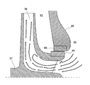
- the pump often has an “inlet back flow” accompanied by cavitation in the impeller at a low flow rate. This is because the flow rate is limited by opening and closing a valve installed on the downstream side of the impeller.
- This inlet backflow phenomenon is a flow in which the fluid recirculates from the inside of the impeller 59 to the suction side flow path 61 as shown in FIG. Since the reverse flow of the inlet is also close to the casing ring 69, it also contacts the partition wall 65 close to the casing ring 69 and further promotes erosion.
- the first means for solving the problem is an erosion prevention structure in the vicinity of a facing portion between the casing and the impeller, the casing, a casing ring that is installed in the casing and faces the impeller, and the casing And an electrically insulating material provided between the casing ring and the casing ring.
- the second means is the corrosion erosion prevention structure according to means 1, wherein the electrical insulating material includes an epoxy-based material or a silicon-based material.
- the electrical insulating material includes an epoxy-based material or a silicon-based material.
- the third means is the structure for preventing corrosion and erosion according to means 1 or 2, wherein an O-ring for sealing is disposed at the boundary surface between the casing and the casing ring.
- an O-ring for sealing is disposed at the boundary surface between the casing and the casing ring.
- the fourth means is any one of the means 1 to 3, wherein an outer edge extension extending from the portion facing the impeller toward the radially outward direction of the pump main shaft is provided on the low pressure side of the casing ring. It is a structure for preventing corrosion and erosion as described in the item. By doing in this way, the casing ring also spreads outward in the radius of the suction flow path, and the backflow cavitation does not directly hit the casing but is protected by the casing ring.
- the fifth means is the corrosion erosion according to means 4, wherein the difference between the angle at the tip of the outer edge extension and the angle of the outer edge of the impeller facing the tip of the outer edge is within 10 degrees. It is a prevention structure. By doing so, the flow of the liquid becomes smooth and the loss caused by the step is reduced.
- the sixth means is the corrosion erosion prevention structure according to any one of means 1 to 5, wherein the casing ring is configured by combining two members.
- Seventh means includes the corrosion erosion prevention structure according to any one of means 1 to 6, a pump main shaft rotatably supported by the casing, an impeller mounted on the pump main shaft, And a liquid channel formed inside the casing.
- the eighth means is a method of manufacturing a pump comprising a casing and an impeller, wherein the casing is provided, an electrical insulating material is provided at a predetermined location of the casing, and a predetermined casing ring facing the impeller is provided with the electric It is a manufacturing method of a pump installed in the casing via an insulating material.
- Ninth means is a method of repairing a pump comprising a casing and an impeller, wherein an electrical insulating material is provided at a predetermined location of the casing, and a predetermined casing ring facing the impeller is provided via the electrical insulating material. This is a method for repairing the pump installed in the casing.
- FIG. 6 is an enlarged view of a portion B in FIG. 5. It is an expanded sectional view of embodiment in the pump of the form different from one Embodiment of this invention. It is an expanded sectional view of another embodiment in the pump of the form different from one Embodiment of this invention.
- FIG. 1 is a cross-sectional view showing an overall outline of a double suction spiral pump 1 according to the present embodiment.
- the pump 1 includes an upper casing 3, a lower casing 5, a rotating shaft 7 installed in a boundary region between the casings 3 and 5, and an impeller 9 provided on the rotating shaft 7.
- a suction side flow path 11 and a discharge side flow path 13 are formed in both casings 3 and 5 via an impeller 9.
- the suction side flow path 11 and the discharge side flow path 13 are fluid flow paths.
- the pump 1 of the present embodiment is a double-suction centrifugal pump that sucks liquid from both sides around the discharge-side flow path 13.
- the partition 15 which separates the suction side flow path 11 and the discharge side flow path 13 is provided in the casings 3 and 5.
- One of the features of the present embodiment is the structure in the vicinity of the end portion of the partition wall 15 of the casings 3 and 5 and the portion facing (sliding) the impeller 9. The facing portion is shown as region A in this figure.
- a prime mover such as an electric motor (not shown) is engaged with the rotary shaft 7 of the pump 1.
- the impeller 9 installed on the rotary shaft 7 is rotated by the driving force of the prime mover.
- the rotating shaft 7 is provided along the horizontal direction.
- the impeller 9 rotates along a vertical plane crossing the rotation shaft 7.
- the horizontal axis of rotation in this embodiment is an example, and it may be installed along the vertical direction or other angular directions.
- the rotating shaft 7 is sandwiched between the upper casing 3 and the lower casing 5 via a bearing 7a.
- the part where the bearing 7a is installed is basically a boundary between the suction side flow path 11 inside the pump and the external environment.
- the bearing 7a is provided with a seal structure (not shown) so that the liquid in the suction side channel 11 does not leak to the outside.
- the impeller 9 rotates with the rotation of the rotary shaft 7 and sucks liquid from the suction side flow paths 11 on both sides around the discharge side flow path 13.
- the inflow portion 9a of the impeller 9 is formed in the vicinity of the rotating shaft 7, but the suction side flow path 11 is formed to the outside in the radial direction from the inflow portion 9a. For this reason, in the suction side flow path 11, the radially inward flow flows into the inflow portion 9 a of the impeller 9.
- the rotational energy of the impeller 9 is given as centrifugal force to the fluid flowing inside. This centrifugal force gives kinetic energy. As a result, the rotational energy of the impeller 9 is eventually converted into pressure energy and kinetic energy.
- the pressure in the discharge side flow path 13 is relatively higher than the pressure in the suction side flow path 11.
- a part of the casing is provided as a partition wall 15 so as to separate the suction side flow path 11 on the low pressure side and the discharge side flow path 13 on the high pressure side.
- a casing ring 19 is provided on the partition wall 15 of the casing at the end of the partition wall 15 of the casings 3 and 5 and facing (sliding) the impeller 9 (region A in FIG. 1).
- a ring 10 is provided. This point will be described in detail in the explanation of enlarged views shown in FIGS. Needless to say, the same structure as that of the region A is also present in a portion symmetric with respect to the rotation axis 7 and a portion symmetric with respect to the center line L in the drawing.
- the impeller 9 and the impeller ring 10 are substantially the same as the conventional one.
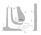
- the structure on the casing side is different from the conventional pump. That is, the electrical insulating material 17A is provided between the casing ring 19 and the end of the partition wall 15 of the casing.
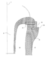
- the electrical insulating material 17 ⁇ / b> A of the present embodiment has a semicircular shape, and is filled so as to be in close contact with the casing ring 19 and the partition wall 15. As described above, since the electrical insulating material 17A is in close contact with the casing ring 19 and the partition wall 15, no gap is formed between the casing ring 19 and the partition wall 15, and no leakage flow occurs. Electrical contact can also be prevented.
- the resin material such as an insulating film, an insulating paint, and an insulating adhesive can be used for the electrical insulating material 17A.
- fiber reinforced plastics and particle reinforced plastics can also be used.
- insulating low-melting glass, ceramic adhesive, or the like may be used.
- an epoxy-based, silicon-based, or PTFE-based electrically insulating material is preferable as a suitable material. Even when these materials are used in water, there is almost no outflow or absorption of components into the water, so that there is almost no deterioration even when used over a long period of time.
- the epoxy-based or silicon-based electrically insulating material is a liquid or gel-like insulating paint or insulating adhesive, adhesion (affinity) to the metal surface is good. For this reason, when an electrically insulating material is applied to at least one of the partition wall 15 and the casing ring 19 of the casing and the application surfaces thereof are aligned with the mating surface, the surface spreads to the mating surface of the casing partition wall 15 and the casing ring 19. A film-like layer of an electrically insulating material is formed between the two. This film-like layer becomes the electrical insulating material 17A of the present embodiment. This film-like layer gradually cures to some extent and becomes solid. The solid film-like layer has high adhesion strength and fracture strength.
- the electrical insulating material 17A does not break or come off and maintains the adhesion. To do. For this reason, while maintaining so that the pressurized fluid may not distribute
- the electrically insulating material is silicon or PTFE
- the thickness of the electrically insulating material filling is preferably in the range of 0.005 mm to 2 mm, for example, but 0.05 mm or more is preferably a film, and if it is less than 0.05 mm, an insulating paint or an insulating adhesive can be applied. preferable.
- the cross-sectional shape of the electrical insulating material 17A is a rectangular wave shape. By doing so, even when an impact or the like is applied to the partition wall 15 or the casing ring 19, the electrically insulating material is prevented from peeling off from the partition wall 15 or the like.
- the cross-sectional shape is an example, and the present invention is not limited to this.
- FIG. 3 is a diagram showing a second embodiment.
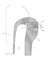
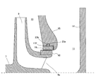
- This embodiment is a corrosion erosion prevention structure in which an electrical insulating O-ring is mounted in addition to the electrical insulating material 17. That is, an O-ring groove 23a is formed on the outer peripheral surface of the casing ring 19, and the O-ring 23b is fitted in the O-ring groove 23a.
- the electrically insulating material 17B is broken or peeled off from the casing ring 19 or the casing 15 due to vibration of the pump, impact during sliding, frictional heat, or the like. Even in this case, the sealing performance can be maintained by the O-ring.
- the sealing performance can be maintained so that liquid does not pass through the gap.
- the casing ring 19 and the partition wall 15 of the casing are further reinforced so as not to make electrical contact.
- the O-ring is responsible for maintaining the sealing performance so as to prevent leakage flow.
- the electrical insulating material 17B sandwiched between the mating surfaces of the casing ring 19 and the partition wall 15 is not required to have much adhesiveness with the mating surfaces.
- the contact pressure between the casing ring 19 and the partition wall 15 is not uniform before and after the O-ring with the O-ring as a fulcrum (left and right of the O-ring in FIG. 3).
- the electrical insulating material 17 sandwiched between the mating surfaces of the casing ring 19 and the partition wall 15 prevents the casing ring 19 and the partition wall 15 from being in contact with each other, and the contact pressure applied to these mating surfaces is reduced.
- FIG. 4 shows a third embodiment.
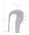
- the corrosion erosion prevention structure in which the outer edge of the casing ring 19 on the low pressure (suction side flow path 11) side extends radially outward of the rotating shaft is shown.
- the extending portion is referred to as an outer edge extension portion 19A.
- An outer edge extension 19A on the low pressure side of the casing ring 19 covers the partition wall 15 of the casing in a wide range.
- the diameter of the outer edge extension 19 ⁇ / b> A extending outward in the radial direction with respect to the rotation axis is sufficient up to about 1.5 times the diameter of the inflow portion 9 a of the impeller 9.
- an electrical insulating material 17C having a predetermined thickness is also filled between the outer edge extension 19A and the partition wall 15.
- the casing ring 19 is made of a metal resistant to erosion, for example, stainless cast steel, and the casing (partition 15) is less susceptible to erosion than stainless cast steel, but is a general-purpose metal. For example, even if it is made of cast iron, the partition wall 15 can be protected from cavitation erosion.
- the suction flow path is not necessarily axisymmetric with respect to the rotation axis of the pump, but is often non-axisymmetric. It is desirable to manufacture the outer edge extension portion in a non-axisymmetric manner in accordance with the shape of the suction flow path so that the path and the outer edge extension portion 19A are smoothly connected.
- FIG. 5 shows a fourth embodiment.
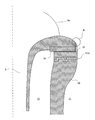
- 9a is a corrosion erosion prevention structure in which the difference from the inclination of the outer edge facing the casing ring 19 side is within about 10 degrees (region B in the figure).
- FIG. 6 is an enlarged view of region B in FIG.
- the inclination angle of the outer edge of the casing ring 19 facing the inflow portion side of the adjacent impeller 9 is ⁇ ′ degree, and the inclination of the outer edge of the inflow portion of the impeller 9 facing the casing ring 19 side.
- the angle is ⁇ degrees.
- FIG. 7 is a diagram showing the main part of an example in which the structure for preventing corrosion and corrosion according to the present embodiment is applied to a pump of a type in which a radially inward flow flows into the inflow portion 9a of the impeller 9.
- the electrical insulating material 17E of this embodiment has an L-shaped cross section.
- a prime mover such as an electric motor (not shown) is engaged with the rotary shaft 7 of the pump, and the impeller 9 is rotated by the driving force of the prime mover.
- the liquid flowing in the internal flow path passes through the suction side flow path 11 between the side cover 14 and the partition wall 15 of the casing, and flows inward in the radial direction from the outside of the rotating shaft 7. Then, it flows into the inflow portion 9a of the impeller 9 as indicated by an arrow C in the figure.
- the liquid that has flowed into the impeller 9 from the suction side flow path 11 receives the rotational energy of the impeller 9 and is converted into a liquid whose pressure energy and kinetic energy are increased by centrifugal force.
- the pressure of the discharge side flow path 13 is relatively higher than that of the suction side flow path 11, and in order to maintain this pressure, the suction side flow path 11 and the discharge side flow path 13 are separated by the partition wall 15 of the casing portion. It is separated.
- the impeller 9 rotates along a vertical plane that crosses the rotary shaft 7.
- the horizontal axis of rotation in this embodiment is an example, and it may be installed along the vertical direction or other angular directions.
- the casing ring 19 is provided in the partition wall 15 of the casing and the impeller ring 10 is provided in the impeller 9 at the end of the partition wall 15 of the casing and facing the impeller 9.
- An electrical insulating material 17 is provided between the casing ring 19 and the end of the partition wall 15 of the casing.
- the electrical insulating material 17E is filled so as to be in close contact with the casing ring 19 and the partition wall 15 of the casing. Has been. Since the electrical insulating material 17E is in intimate contact with the casing ring 19 and the partition wall 15, no gap is formed between the casing ring 19 and the partition wall 15, thereby preventing fluid leakage and preventing the casing ring 19 and the partition wall 15 from Electric contact can also be prevented.
- the electrical insulating material 17E may use any resin material such as an insulating film, an insulating paint, and an insulating adhesive, and may be formed as a fiber reinforced plastic or a particle reinforced plastic. In addition to resin materials, insulating low-melting glass, ceramic adhesive, and the like may be used. However, it is necessary to maintain the functions of maintaining electrical insulation, maintaining sealing properties, and maintaining dimensional accuracy by absorbing vibrations, shocks, and temperature changes in pump operation over a long period of time. For this reason, an epoxy-based, silicon-based, or PTFE-based electrically insulating material is preferable as a suitable material. Even when these materials are used in water, there is almost no outflow or absorption of components into the water, so there is almost no deterioration even during long-term use.
- An epoxy-based or silicon-based electrically insulating material has good adhesion (affinity) to a metal surface if it is a liquid or gel-like insulating paint or insulating adhesive. For this reason, when this is applied to one or both of the casing and the casing ring, and the application surfaces thereof are aligned with the mating surface, the coating agent spreads on the mating surface of the casing and the casing ring, and an electrically insulating material between the two A film-like layer is formed. This film-like layer gradually cures to some extent and becomes solid.
- the solid film-like layer has high adhesion strength and fracture strength, and even when the pump is operated for a long period of time, even if there is vibration of the pump, impact during sliding, frictional heat, etc., the electrically insulating material Does not break or come off and maintains adhesion. For this reason, a gap is not formed between the casing ring and the casing, and the liquid is kept from leaking, and electrical contact and electrical continuity between the casing ring and the casing are prevented.
- the electrically insulating material is silicon or PTFE
- the filling thickness of the electrical insulating material 17E is preferably in the range of about 0.005 mm to 2 mm, but 0.05 mm or more is preferably in the form of a film, and if it is less than 0.05 mm, an insulating paint or an insulating adhesive can be applied. preferable.
- FIG. 8 shows a corrosion / erosion prevention structure equipped with an electrically insulating O-ring 23b in addition to the electrically insulating material 17F disclosed in FIG.
- the O-ring 23 b is mounted in an O-ring groove 23 a formed in the partition wall 15.
- the electrically insulating material 17F may break or peel from the casing ring 19 or the casing 15 due to vibration of the pump, impact during sliding, frictional heat, or the like.
- the sealing performance is maintained by the O-ring 23b, the liquid is continuously maintained so as not to flow through the gap, and the casing ring 19 and the partition wall 15 of the casing are further reinforced so as not to make electrical contact.
- the O-ring groove 23a may be formed on either the casing ring 19 side or the casing 15 side.
- the electrically insulating O-ring 23b is responsible for maintaining the sealing performance, the electrical insulating material 17F is not required to have much adhesiveness with the mating surface.
- the electrical insulating material 17F is formed with a thickness of 0.05 mm to 10 mm so that the casing ring 19 and the partition wall 15 of the casing do not contact even at one point and in order to receive the contact pressure applied to their mating surfaces. It is also desirable to insert it as a silicon-based or PTFE-based component.
- FIG. 9 shows a corrosion / erosion prevention structure in which the outer edge of the casing ring 19a on the low pressure side, that is, the suction side flow path 11 side, extends outward in the radial direction of the pump shaft.
- This extending portion is an outer edge extension 19A.
- the casing ring 19 is divided into two parts, a first member 19a and a second member 19b. For this reason, even when the joining shape of the electrically insulating material 17G is complicated as shown in the figure, the first member 19a is disposed on the impeller 9 side, and the second member 19b is disposed on the suction side flow path 11 side. Can be assembled by fixing with screws 21.
- the above-described corrosion erosion prevention structure enables assembly of the corrosion erosion prevention structure including the outer edge extension portion 19A even in a pump (such as a ring-cut type) in which the upper casing and the lower casing are not separated.
- the low pressure side of the second portion 19b of the casing ring 19 covers the partition wall 15 in a wide range. By doing in this way, even if the inlet back flow accompanied by cavitation occurs from the impeller 9 to the suction side flow path 11 during the low flow rate operation of the pump, the second portion 19b protects the partition wall 15, so that erosion progresses. Can be prevented.
- the second portion 19b of the casing ring 19 is made of a metal that is resistant to erosion, for example, stainless cast steel, and the partition wall 15 of the casing is less susceptible to erosion than the second portion 19b of the casing ring 19 but is made of a general-purpose metal, for example, cast iron.
- the partition wall 15 of the casing can be protected from cavitation erosion.
- the present invention can also be defined as a method for manufacturing a pump. That is, a method of manufacturing a pump including a casing and an impeller, wherein the casing is provided, an electrical insulating material is provided at a predetermined position of the casing, and a predetermined casing ring facing the impeller is interposed via the electrical insulating material.
- the pump is installed in the casing.
- the present invention can also be defined as a pump repair method. That is, a method of repairing a pump including a casing and an impeller, wherein an electrical insulating material is provided at a predetermined location of the casing, and a predetermined casing ring facing the impeller is attached to the casing via the electrical insulating material.
- This is a repair method for the pump. The repair is performed after disassembling the pump once.
- the present invention is not limited to the embodiment shown in FIG. 1 and FIG. 9, and is a pump that pressurizes and transfers a liquid. can do.
Landscapes
- Engineering & Computer Science (AREA)
- Mechanical Engineering (AREA)
- General Engineering & Computer Science (AREA)
- Structures Of Non-Positive Displacement Pumps (AREA)
Abstract
Description
1)ケーシングリングとケーシング間の腐食の防止、
2)上記腐食に起因するケーシングリングとケーシング間の漏れ流れの防止、
3)漏れ流れによるキャビテーション壊食の防止、さらに
4)低流量時にポンプ吸込み口近傍に生ずる「入口逆流」のキャビテーションによるポンプケーシングリング近傍の壊食を防止、
をすることが可能となる。
図1は、本実施形態に係る両吸込渦巻き型のポンプ1の全体概要を示す断面図である。ポンプ1は、上ケーシング3と、下ケーシング5と、これら両ケーシング3,5の境界領域に設置される回転軸7と、当該回転軸7に設けられるインペラ9とを備えている。そして両ケーシング3,5内には、インペラ9を介して吸込側流路11と吐出側流路13とが形成されている。これら吸込側流路11と吐出側流路13が流体流路となる。
上述したように、本実施形態のポンプ1は、吐出側流路13を中心として両側から液体を吸い込む形式の両吸込渦巻きポンプである。このため、ケーシング3、5の内部に、吸込側流路11と吐出側流路13を隔てる隔壁15が設けられている。本実施形態の特徴の一つは、このケーシング3,5の隔壁15の端部であって、インペラ9と対向(摺動)する部位の近傍の構造である。その対向部位を、この図においては、領域Aとして示している。
ポンプ1の回転軸7には、図示しない電動モータなどの原動機が係合されている。この原動機の駆動力により、回転軸7に設置されたインペラ9が回転するようになっている。本実施形態のポンプ1では、回転軸7が水平方向に沿って設けられている。このため、インペラ9は回転軸7を横切る垂直面に沿って回転することとなる。ただし、本実施形態における水平方向の回転軸は一例であって、垂直方向やそれ以外の角度方向に沿って設置してもよい。回転軸7は、軸受7aを介して、上ケーシング3と下ケーシング5の間に挟まれている。この軸受7aが設置される部位は、基本的にポンプ内部の吸込側流路11と外部環境との境界となっている。このため、吸込側流路11内の液体が外部に漏れないように、軸受7aにはシール構造(図示略)が設けられている。
インペラ9は、回転軸7の回転に伴い回転し、吐出側流路13を中心として両側の吸込側流路11から液体を吸い込む。インペラ9の流入部9aは回転軸7の近傍に形成されているが、吸込側流路11は上記流入部9aよりも半径方向外側まで形成されている。このため、吸込側流路11では、半径方向内向き流れが、インペラ9の流入部9aに流入する。インペラ9の回転エネルギーは、内部を流れる流体に対して遠心力として付与される。この遠心力によって運動エネルギーが与えられる。これにより、結果的にはインペラ9の回転エネルギーが圧力エネルギーと運動エネルギーに変換されるのである。従って、吐出側流路13の圧力は、相対的に吸込側流路11の圧力より高い圧力となる。この圧力を保持するために、低圧側の吸込側流路11と高圧側の吐出側流路13を隔てるように、ケーシングの一部が隔壁15として設けられているのである。
図2に示すように、本実施形態に係るポンプでは、インペラ9とインペラリング10については従来のものとほぼ同様ではある。一方、ケーシング側の構造が従来のポンプと異なっている。すなわち、ケーシングリング19とケーシングの隔壁15の端部との間に、電気的絶縁材17Aを設けている点が特徴である。本実施形態の電気的絶縁材17Aは半円形状であり、ケーシングリング19と、隔壁15のそれぞれに密着するような状態で充填されている。このように、電気的絶縁材17Aがケーシングリング19と隔壁15に密着しているので、ケーシングリング19と隔壁15との間には隙間が形成されず、漏れ流れが発生せず、また両者の電気的接触も防ぐことができる。
3 上ケーシング
5 下ケーシング
7 回転軸
9 インペラ
9a 流入部
10 インペラリング
11 吸込側流路
13 吐出側流路
15 ケーシングの隔壁
17A,17B,17C,17D,17E,17F,17G 電気的絶縁材
19 ケーシングリング
19A 外縁延長部
21 ネジ
23a Oリング溝
23b Oリング溝
Claims (9)
- ケーシングとインペラとの対向部位近傍における壊食防止構造であって、
ケーシングと、当該ケーシングに設置されると共に前記インペラに対向するケーシングリングと、前記ケーシングとケーシングリングとの間に設けられる電気的絶縁材とを備えている、腐食壊食防止構造。 - 前記電気的絶縁材は、エポキシ系、シリコン系、PTFE系材料の少なくとも1つを含む、請求項1に記載の腐食壊食防止構造。
- 前記ケーシングとケーシンリングの境界面に、シール用のOリングが配置されている、請求項1又は2に記載の腐食壊食防止構造。
- 前記ケーシングリングの低圧側には、前記インペラとの対向部位からポンプ主軸の半径方向外方に向かって延びる外縁延長部が設けられている、請求項1から3の何れか一項に記載の腐食壊食防止構造。
- 前記外縁延長部の先端部における角度と、当該外縁の先端部に対向する前記インペラの外縁の角度とは、差が10度以内である、請求項4に記載の腐食壊食防止構造。
- 前記ケーシングリングは2つの部材を組み合わせて構成されている、請求項1から5の何れか一項に記載の腐食壊食防止構造。
- 請求項1から6の何れか一項に記載の腐食壊食防止構造と、前記ケーシングによって回転自在に支持されているポンプ主軸と、該ポンプ主軸に装着されたインペラと、前記ケーシング内部に形成される液体流路、とを備えたポンプ。
- ケーシングとインペラとを備えるポンプの製造方法であって、
前記ケーシング備え、
前記ケーシングの所定箇所に電気的絶縁材を設け、
前記インペラに対向する所定のケーシングリングを、前記電気絶縁材料を介して前記ケーシングに設置する、ポンプの製造方法。 - ケーシングとインペラとを備えるポンプの補修方法であって、
前記ケーシングの所定箇所に電気的絶縁材を設け、
前記インペラに対向する所定のケーシングリングを、前記電気絶縁材料を介して前記ケーシングに設置する、ポンプの補修方法。
Priority Applications (3)
| Application Number | Priority Date | Filing Date | Title |
|---|---|---|---|
| CN201480035966.7A CN105339674A (zh) | 2013-06-27 | 2014-06-10 | 防止腐蚀侵蚀构造及具备该构造的泵、以及泵的制造方法及修补方法 |
| JP2015523961A JPWO2014208327A1 (ja) | 2013-06-27 | 2014-06-10 | 腐食壊食防止構造およびこれを備えるポンプ、並びにポンプの製造方法および補修方法 |
| SA515370324A SA515370324B1 (ar) | 2013-06-27 | 2015-12-27 | بنية مانعة للتآكل والتعرية، ومضخة تشتمل عليها، وطريقة لتصنيع المضخة وإصلاحها |
Applications Claiming Priority (2)
| Application Number | Priority Date | Filing Date | Title |
|---|---|---|---|
| JP2013-135228 | 2013-06-27 | ||
| JP2013135228 | 2013-06-27 |
Publications (1)
| Publication Number | Publication Date |
|---|---|
| WO2014208327A1 true WO2014208327A1 (ja) | 2014-12-31 |
Family
ID=52141672
Family Applications (1)
| Application Number | Title | Priority Date | Filing Date |
|---|---|---|---|
| PCT/JP2014/065291 Ceased WO2014208327A1 (ja) | 2013-06-27 | 2014-06-10 | 腐食壊食防止構造およびこれを備えるポンプ、並びにポンプの製造方法および補修方法 |
Country Status (4)
| Country | Link |
|---|---|
| JP (2) | JPWO2014208327A1 (ja) |
| CN (1) | CN105339674A (ja) |
| SA (1) | SA515370324B1 (ja) |
| WO (1) | WO2014208327A1 (ja) |
Cited By (1)
| Publication number | Priority date | Publication date | Assignee | Title |
|---|---|---|---|---|
| JP2019190292A (ja) * | 2018-04-19 | 2019-10-31 | 株式会社荏原製作所 | ライナーリング、ポンプ、およびケーシングの補修に使用されるテンプレート、並びにポンプのケーシングを補修する方法 |
Families Citing this family (1)
| Publication number | Priority date | Publication date | Assignee | Title |
|---|---|---|---|---|
| CN108468657A (zh) * | 2018-04-09 | 2018-08-31 | 捷达消防科技(苏州)股份有限公司 | 消防车用的消防泵结构 |
Citations (5)
| Publication number | Priority date | Publication date | Assignee | Title |
|---|---|---|---|---|
| JPS6119697U (ja) * | 1984-07-10 | 1986-02-04 | 株式会社クボタ | 両吸込渦巻ポンプ |
| JP2001323893A (ja) * | 2000-05-16 | 2001-11-22 | Shimadzu Corp | 高速回転機器 |
| JP2002257082A (ja) * | 2001-02-28 | 2002-09-11 | Teral Kyokuto Inc | ポンプのライナリング |
| JP2003013884A (ja) * | 2001-07-02 | 2003-01-15 | Tsurumi Mfg Co Ltd | 水中回転機械における羽根車固定端面の腐食溶解防止構造 |
| JP2013047510A (ja) * | 2011-07-25 | 2013-03-07 | Nidec Sankyo Corp | カスケードポンプ装置 |
Family Cites Families (8)
| Publication number | Priority date | Publication date | Assignee | Title |
|---|---|---|---|---|
| JP2529919Y2 (ja) * | 1991-05-08 | 1997-03-26 | 三菱重工業株式会社 | 絶縁材一体型ウエアリング付ポンプ |
| JPH09329081A (ja) * | 1996-06-12 | 1997-12-22 | Toshiba Corp | 圧縮機 |
| CN200999749Y (zh) * | 2007-01-12 | 2008-01-02 | 上海连成(集团)有限公司 | 一种新型水泵叶轮密封装置 |
| CN201144858Y (zh) * | 2007-12-18 | 2008-11-05 | 兰州理工大学 | 一种新型离心泵用密封环 |
| CN201391481Y (zh) * | 2009-05-26 | 2010-01-27 | 湖南斯德尔重工科技有限公司 | 泵用带密封圈的密封环 |
| CN201771849U (zh) * | 2010-07-13 | 2011-03-23 | 山东双轮股份有限公司 | 抗抱死水泵叶轮 |
| CN201747666U (zh) * | 2010-08-03 | 2011-02-16 | 上海凯泉泵业(集团)有限公司 | 大流量高扬程双吸泵的密封环结构 |
| CN201934361U (zh) * | 2010-11-03 | 2011-08-17 | 西安泵阀总厂有限公司 | 离心泵镶嵌式密封环结构 |
-
2014
- 2014-06-10 WO PCT/JP2014/065291 patent/WO2014208327A1/ja not_active Ceased
- 2014-06-10 JP JP2015523961A patent/JPWO2014208327A1/ja active Pending
- 2014-06-10 CN CN201480035966.7A patent/CN105339674A/zh active Pending
-
2015
- 2015-12-27 SA SA515370324A patent/SA515370324B1/ar unknown
-
2017
- 2017-10-18 JP JP2017201931A patent/JP6469811B2/ja active Active
Patent Citations (5)
| Publication number | Priority date | Publication date | Assignee | Title |
|---|---|---|---|---|
| JPS6119697U (ja) * | 1984-07-10 | 1986-02-04 | 株式会社クボタ | 両吸込渦巻ポンプ |
| JP2001323893A (ja) * | 2000-05-16 | 2001-11-22 | Shimadzu Corp | 高速回転機器 |
| JP2002257082A (ja) * | 2001-02-28 | 2002-09-11 | Teral Kyokuto Inc | ポンプのライナリング |
| JP2003013884A (ja) * | 2001-07-02 | 2003-01-15 | Tsurumi Mfg Co Ltd | 水中回転機械における羽根車固定端面の腐食溶解防止構造 |
| JP2013047510A (ja) * | 2011-07-25 | 2013-03-07 | Nidec Sankyo Corp | カスケードポンプ装置 |
Cited By (2)
| Publication number | Priority date | Publication date | Assignee | Title |
|---|---|---|---|---|
| JP2019190292A (ja) * | 2018-04-19 | 2019-10-31 | 株式会社荏原製作所 | ライナーリング、ポンプ、およびケーシングの補修に使用されるテンプレート、並びにポンプのケーシングを補修する方法 |
| JP7262928B2 (ja) | 2018-04-19 | 2023-04-24 | 株式会社荏原製作所 | ライナーリングを備えたポンプのケーシングの補修方法 |
Also Published As
| Publication number | Publication date |
|---|---|
| JP6469811B2 (ja) | 2019-02-13 |
| CN105339674A (zh) | 2016-02-17 |
| JPWO2014208327A1 (ja) | 2017-02-23 |
| SA515370324B1 (ar) | 2020-12-06 |
| JP2018040363A (ja) | 2018-03-15 |
Similar Documents
| Publication | Publication Date | Title |
|---|---|---|
| JP5575202B2 (ja) | 磁気駆動ポンプ | |
| US9494239B2 (en) | Sliding parts | |
| US9086075B2 (en) | Impeller assembly and method | |
| US9447884B2 (en) | Sliding parts | |
| US20130171011A1 (en) | Rotodynamic Pump With Permanent Magnet Coupling Inside The Impeller | |
| CN107250507B (zh) | 叶轮盖、旋转机械及叶轮盖的制造方法 | |
| JP6001707B2 (ja) | 過給機用のコンプレッサハウジング | |
| JP6177421B2 (ja) | シール構造及び該シール構造を備える過給機 | |
| US20070280823A1 (en) | Seal device for a fluid machine | |
| JP5767636B2 (ja) | 真空ポンプ | |
| JP6469811B2 (ja) | 腐食壊食防止構造およびこれを備えるポンプ、並びにポンプの製造方法および補修方法 | |
| CA2797164C (en) | Centrifugal pump for slurries | |
| JP2019052637A (ja) | ターボ機械圧縮機用摩耗性シール組成物 | |
| WO2012105116A1 (ja) | 真空ポンプの回転体と、これに対向設置する固定部材、及び、これらを備えた真空ポンプ | |
| CA2750073A1 (en) | Liquid ring pump with liner | |
| CN102725535A (zh) | 真空泵 | |
| JP2017020412A (ja) | 流体機械および軸封装置 | |
| CN100504072C (zh) | 离心泵口环密封装置 | |
| JP2011236823A (ja) | スクリュー圧縮機 | |
| KR102104416B1 (ko) | 원심 압축기 | |
| JP5517880B2 (ja) | 渦流れ形ポンプ装置 | |
| CN106015099B (zh) | 压载泵蜗壳 | |
| JP6421105B2 (ja) | ポンプ装置 | |
| CN115681541A (zh) | 一种密封件及电动阀 | |
| CN217152288U (zh) | 一种具有静密封的流体泵 |
Legal Events
| Date | Code | Title | Description |
|---|---|---|---|
| WWE | Wipo information: entry into national phase |
Ref document number: 201480035966.7 Country of ref document: CN |
|
| 121 | Ep: the epo has been informed by wipo that ep was designated in this application |
Ref document number: 14818551 Country of ref document: EP Kind code of ref document: A1 |
|
| ENP | Entry into the national phase |
Ref document number: 2015523961 Country of ref document: JP Kind code of ref document: A |
|
| NENP | Non-entry into the national phase |
Ref country code: DE |
|
| 122 | Ep: pct application non-entry in european phase |
Ref document number: 14818551 Country of ref document: EP Kind code of ref document: A1 |