WO2014208020A1 - 車載用の電装予備蓄電装置及びこの電装予備蓄電装置を備える車両 - Google Patents
車載用の電装予備蓄電装置及びこの電装予備蓄電装置を備える車両 Download PDFInfo
- Publication number
- WO2014208020A1 WO2014208020A1 PCT/JP2014/003034 JP2014003034W WO2014208020A1 WO 2014208020 A1 WO2014208020 A1 WO 2014208020A1 JP 2014003034 W JP2014003034 W JP 2014003034W WO 2014208020 A1 WO2014208020 A1 WO 2014208020A1
- Authority
- WO
- WIPO (PCT)
- Prior art keywords
- storage device
- vehicle
- electrical
- hole
- hole portion
- Prior art date
- Legal status (The legal status is an assumption and is not a legal conclusion. Google has not performed a legal analysis and makes no representation as to the accuracy of the status listed.)
- Ceased
Links
Images



Classifications
-
- H—ELECTRICITY
- H01—ELECTRIC ELEMENTS
- H01M—PROCESSES OR MEANS, e.g. BATTERIES, FOR THE DIRECT CONVERSION OF CHEMICAL ENERGY INTO ELECTRICAL ENERGY
- H01M10/00—Secondary cells; Manufacture thereof
- H01M10/04—Construction or manufacture in general
- H01M10/0445—Multimode batteries, e.g. containing auxiliary cells or electrodes switchable in parallel or series connections
-
- B—PERFORMING OPERATIONS; TRANSPORTING
- B60—VEHICLES IN GENERAL
- B60L—PROPULSION OF ELECTRICALLY-PROPELLED VEHICLES; SUPPLYING ELECTRIC POWER FOR AUXILIARY EQUIPMENT OF ELECTRICALLY-PROPELLED VEHICLES; ELECTRODYNAMIC BRAKE SYSTEMS FOR VEHICLES IN GENERAL; MAGNETIC SUSPENSION OR LEVITATION FOR VEHICLES; MONITORING OPERATING VARIABLES OF ELECTRICALLY-PROPELLED VEHICLES; ELECTRIC SAFETY DEVICES FOR ELECTRICALLY-PROPELLED VEHICLES
- B60L50/00—Electric propulsion with power supplied within the vehicle
- B60L50/50—Electric propulsion with power supplied within the vehicle using propulsion power supplied by batteries or fuel cells
- B60L50/60—Electric propulsion with power supplied within the vehicle using propulsion power supplied by batteries or fuel cells using power supplied by batteries
- B60L50/64—Constructional details of batteries specially adapted for electric vehicles
-
- H—ELECTRICITY
- H01—ELECTRIC ELEMENTS
- H01M—PROCESSES OR MEANS, e.g. BATTERIES, FOR THE DIRECT CONVERSION OF CHEMICAL ENERGY INTO ELECTRICAL ENERGY
- H01M50/00—Constructional details or processes of manufacture of the non-active parts of electrochemical cells other than fuel cells, e.g. hybrid cells
- H01M50/20—Mountings; Secondary casings or frames; Racks, modules or packs; Suspension devices; Shock absorbers; Transport or carrying devices; Holders
- H01M50/204—Racks, modules or packs for multiple batteries or multiple cells
-
- H—ELECTRICITY
- H01—ELECTRIC ELEMENTS
- H01M—PROCESSES OR MEANS, e.g. BATTERIES, FOR THE DIRECT CONVERSION OF CHEMICAL ENERGY INTO ELECTRICAL ENERGY
- H01M50/00—Constructional details or processes of manufacture of the non-active parts of electrochemical cells other than fuel cells, e.g. hybrid cells
- H01M50/20—Mountings; Secondary casings or frames; Racks, modules or packs; Suspension devices; Shock absorbers; Transport or carrying devices; Holders
- H01M50/218—Mountings; Secondary casings or frames; Racks, modules or packs; Suspension devices; Shock absorbers; Transport or carrying devices; Holders characterised by the material
- H01M50/22—Mountings; Secondary casings or frames; Racks, modules or packs; Suspension devices; Shock absorbers; Transport or carrying devices; Holders characterised by the material of the casings or racks
- H01M50/227—Organic material
-
- H—ELECTRICITY
- H01—ELECTRIC ELEMENTS
- H01M—PROCESSES OR MEANS, e.g. BATTERIES, FOR THE DIRECT CONVERSION OF CHEMICAL ENERGY INTO ELECTRICAL ENERGY
- H01M50/00—Constructional details or processes of manufacture of the non-active parts of electrochemical cells other than fuel cells, e.g. hybrid cells
- H01M50/20—Mountings; Secondary casings or frames; Racks, modules or packs; Suspension devices; Shock absorbers; Transport or carrying devices; Holders
- H01M50/233—Mountings; Secondary casings or frames; Racks, modules or packs; Suspension devices; Shock absorbers; Transport or carrying devices; Holders characterised by physical properties of casings or racks, e.g. dimensions
- H01M50/24—Mountings; Secondary casings or frames; Racks, modules or packs; Suspension devices; Shock absorbers; Transport or carrying devices; Holders characterised by physical properties of casings or racks, e.g. dimensions adapted for protecting batteries from their environment, e.g. from corrosion
-
- H—ELECTRICITY
- H01—ELECTRIC ELEMENTS
- H01M—PROCESSES OR MEANS, e.g. BATTERIES, FOR THE DIRECT CONVERSION OF CHEMICAL ENERGY INTO ELECTRICAL ENERGY
- H01M50/00—Constructional details or processes of manufacture of the non-active parts of electrochemical cells other than fuel cells, e.g. hybrid cells
- H01M50/20—Mountings; Secondary casings or frames; Racks, modules or packs; Suspension devices; Shock absorbers; Transport or carrying devices; Holders
- H01M50/249—Mountings; Secondary casings or frames; Racks, modules or packs; Suspension devices; Shock absorbers; Transport or carrying devices; Holders specially adapted for aircraft or vehicles, e.g. cars or trains
-
- H—ELECTRICITY
- H01—ELECTRIC ELEMENTS
- H01M—PROCESSES OR MEANS, e.g. BATTERIES, FOR THE DIRECT CONVERSION OF CHEMICAL ENERGY INTO ELECTRICAL ENERGY
- H01M50/00—Constructional details or processes of manufacture of the non-active parts of electrochemical cells other than fuel cells, e.g. hybrid cells
- H01M50/20—Mountings; Secondary casings or frames; Racks, modules or packs; Suspension devices; Shock absorbers; Transport or carrying devices; Holders
- H01M50/296—Mountings; Secondary casings or frames; Racks, modules or packs; Suspension devices; Shock absorbers; Transport or carrying devices; Holders characterised by terminals of battery packs
-
- H—ELECTRICITY
- H01—ELECTRIC ELEMENTS
- H01M—PROCESSES OR MEANS, e.g. BATTERIES, FOR THE DIRECT CONVERSION OF CHEMICAL ENERGY INTO ELECTRICAL ENERGY
- H01M2220/00—Batteries for particular applications
- H01M2220/20—Batteries in motive systems, e.g. vehicle, ship, plane
-
- Y—GENERAL TAGGING OF NEW TECHNOLOGICAL DEVELOPMENTS; GENERAL TAGGING OF CROSS-SECTIONAL TECHNOLOGIES SPANNING OVER SEVERAL SECTIONS OF THE IPC; TECHNICAL SUBJECTS COVERED BY FORMER USPC CROSS-REFERENCE ART COLLECTIONS [XRACs] AND DIGESTS
- Y02—TECHNOLOGIES OR APPLICATIONS FOR MITIGATION OR ADAPTATION AGAINST CLIMATE CHANGE
- Y02E—REDUCTION OF GREENHOUSE GAS [GHG] EMISSIONS, RELATED TO ENERGY GENERATION, TRANSMISSION OR DISTRIBUTION
- Y02E60/00—Enabling technologies; Technologies with a potential or indirect contribution to GHG emissions mitigation
- Y02E60/10—Energy storage using batteries
-
- Y—GENERAL TAGGING OF NEW TECHNOLOGICAL DEVELOPMENTS; GENERAL TAGGING OF CROSS-SECTIONAL TECHNOLOGIES SPANNING OVER SEVERAL SECTIONS OF THE IPC; TECHNICAL SUBJECTS COVERED BY FORMER USPC CROSS-REFERENCE ART COLLECTIONS [XRACs] AND DIGESTS
- Y02—TECHNOLOGIES OR APPLICATIONS FOR MITIGATION OR ADAPTATION AGAINST CLIMATE CHANGE
- Y02P—CLIMATE CHANGE MITIGATION TECHNOLOGIES IN THE PRODUCTION OR PROCESSING OF GOODS
- Y02P70/00—Climate change mitigation technologies in the production process for final industrial or consumer products
- Y02P70/50—Manufacturing or production processes characterised by the final manufactured product
-
- Y—GENERAL TAGGING OF NEW TECHNOLOGICAL DEVELOPMENTS; GENERAL TAGGING OF CROSS-SECTIONAL TECHNOLOGIES SPANNING OVER SEVERAL SECTIONS OF THE IPC; TECHNICAL SUBJECTS COVERED BY FORMER USPC CROSS-REFERENCE ART COLLECTIONS [XRACs] AND DIGESTS
- Y02—TECHNOLOGIES OR APPLICATIONS FOR MITIGATION OR ADAPTATION AGAINST CLIMATE CHANGE
- Y02T—CLIMATE CHANGE MITIGATION TECHNOLOGIES RELATED TO TRANSPORTATION
- Y02T10/00—Road transport of goods or passengers
- Y02T10/60—Other road transportation technologies with climate change mitigation effect
- Y02T10/70—Energy storage systems for electromobility, e.g. batteries
Definitions
- the present invention relates to an in-vehicle electrical storage power storage unit that is connected in parallel to an electrical battery that supplies power to a vehicle load installed in the vehicle, and a vehicle equipped with the electrical storage power storage unit.
- a conventional vehicle is equipped with a lead battery having a rated voltage of 12V as a battery for electrical equipment, and in a large vehicle, a battery having a rated voltage of 24V by connecting two 12V lead batteries in series. It is equipped with.
- the lead battery is charged by an alternator of the vehicle and supplies electric power to a vehicle load such as an electrical equipment of the vehicle or a starter motor.
- a battery capacity Ah
- an electrical spare power storage device such as a nickel metal hydride battery or a lithium ion secondary battery is connected in parallel with the lead battery.
- a power supply device has been developed (see Patent Document 1).
- the power supply device of Patent Document 1 is connected to an electrical spare storage device composed of a lithium ion secondary battery in parallel with a lead battery electrically connected to a vehicle alternator. Moreover, this power supply device sets a lead battery and a lithium ion secondary battery via a DC / DC converter by setting the internal resistance and open circuit voltage of the lead battery and the lithium ion secondary battery so as to satisfy predetermined conditions. Connected in parallel without any cost to reduce costs.
- the lead battery is placed in the engine room of the vehicle, but the engine room and other equipment are generated Therefore, it is preferable that the electrical auxiliary power storage device be disposed in a place other than the engine room apart from the lead battery.
- an electrical storage battery device such as a lithium ion secondary battery is disposed on a floor surface below a seat installed in the cabin, for example, using a dead space in the cabin (see, for example, Patent Document 2). ).
- the electrical spare power storage device In the structure in which the electrical spare storage device is arranged on the floor surface in the cabin, the electrical spare power storage device is rarely exposed to rainwater, but droplets of juice or tea spilled by the passenger are scattered on the floor surface. In some cases, the electric spare power storage device may enter the inside. Alternatively, water droplets may flow down from an umbrella brought into the cabin and enter the spare electrical storage device. The battery short-circuits when the liquid that has entered the inside of the electrical auxiliary storage device comes into contact with a metal such as an output terminal or a bus bar.
- a main object of the present invention is to provide an electrical spare power storage device that can effectively suppress moisture permeation into a case of the electrical spare power storage device with a simple configuration, and a vehicle including the same.
- the vehicle auxiliary electrical storage device connected in parallel to the electrical battery that supplies electric power to the vehicle load installed on the vehicle.
- a power storage unit having a terminal portion including an output terminal; and a storage case for storing the power storage unit, wherein the storage case includes a hole into which a terminal portion of the power storage unit is fitted, and a peripheral edge of the hole
- a first guide means provided on a wall surface that rises from the wall and prevents liquid droplets flowing down along the wall wall from entering the hole, and provided at a peripheral edge of the hole, from the peripheral edge of the hole
- second guide means for preventing droplets from entering the hole.
- the first guide means is a convex portion integrally formed in a mountain shape together with the wall surface.
- the second guide means is a convex portion integrally formed along the peripheral edge of the hole.
- the second guide means is a groove formed integrally along the peripheral edge of the hole.
- a liquid droplet that has entered the power supply device from the hole is guided to a drain hole formed in the lower part of the storage case, below the hole.
- 3 guide means are provided.
- the third guide means includes a downwardly inclined groove provided inside the hole.
- the inflow side opening of the drainage hole is not flush.
- the storage case includes an upper case and a lower case, and the upper case is connected to the lower case so as to surround the lower case.
- the storage case can be divided into an upper case and a lower case and molded at low cost, and the upper case and the lower case can be easily positioned.
- the power storage unit is a lithium ion secondary battery or a nickel metal hydride battery.
- the above configuration is characterized in that the vehicle is recharged with regenerative energy generated by regenerative braking extremely efficiently, and the fuel consumption of the vehicle can be significantly improved.
- the vehicle is equipped with an electric spare power storage device for a vehicle connected in parallel to an electric battery for supplying electric power to a vehicle load equipped on the vehicle.
- the electrical auxiliary power storage device includes a power storage unit and a storage case for storing the power storage unit, and the storage case has a hole into which a terminal portion of the power storage unit is fitted, and a peripheral portion of the hole.
- the wall surface rising from the wall is provided with a first guide means for preventing the liquid droplet flowing down along the wall surface from entering the hole portion, and the liquid droplet from the peripheral edge portion of the hole portion is formed on the peripheral edge portion of the hole portion.
- Second guide means for preventing entry into the hole is provided.
- FIG. 1 is a schematic configuration diagram of a vehicle equipped with an electrical equipment spare power storage device according to an embodiment of the present invention. It is a block diagram of the vehicle carrying the electrical equipment preliminary electrical storage apparatus which concerns on one embodiment of this invention. It is a perspective view of an electrical equipment preliminary electrical storage apparatus. It is a disassembled perspective view of an electrical equipment preliminary electrical storage apparatus. It is a longitudinal cross-sectional view of an electrical equipment preliminary electrical storage apparatus. It is a perspective view of the state which removed the upper cover of the electrical equipment preliminary electrical storage apparatus. It is a disassembled perspective view which shows the attachment point of an electrical equipment preliminary electrical storage apparatus. It is a perspective view in the state where an output terminal and a lead board were removed from a capacitor.
- each element constituting the present invention may be configured such that a plurality of elements are constituted by the same member and the plurality of elements are shared by one member, and conversely, the function of one member is constituted by a plurality of members. It can also be realized by sharing.
- the contents described in some examples and embodiments may be used in other examples and embodiments.
- FIG. 1 and 2 show a vehicle equipped with an in-vehicle electrical spare power storage device 2 according to Embodiment 1 of the present invention.
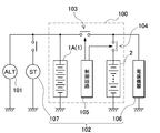
- FIG. 1 is a schematic configuration diagram of a vehicle on which the electrical auxiliary storage device 2 is mounted
- FIG. 2 is a block diagram of the vehicle.
- the vehicles shown in these drawings are equipped with an electrical auxiliary storage device 2 connected in parallel to an electrical battery 1 mounted on the vehicle.
- the vehicle shown in the figure is equipped with a power supply device 100 that supplies electric power to a vehicle load 102 mounted on the vehicle.
- the power supply device 100 includes an electrical equipment battery 1 and an electrical equipment spare power storage device 2.
- the electrical spare power storage device 2 is mounted on the vehicle and connected in parallel to the electrical battery 1 for the purpose of increasing the battery capacity relative to the volume and weight of the power supply device 100 and improving the fuel consumption of the vehicle.
- the electrical equipment battery 1 is charged via the generator 101 mounted on the vehicle, and the electrical equipment spare power storage device 2 is charged. Furthermore, the power supply device 100 discharges from the electric equipment battery 1 and the electric equipment spare power storage device 2 and supplies electric power to the vehicle load 102 such as the starter motor 107 and the electric equipment 106 installed in the vehicle. (Power supply device 100)
- the power supply device 100 shown in FIG. 2 is connected via the first switch 103 so that the electrical battery 1 and the electrical standby power storage device 2 can be connected in parallel to each other.
- the power supply device 100 connects the electrical battery 1 and the electrical spare storage device 2 in parallel with the first switch 103 turned on, and the electrical battery 1 and the electrical spare with the first switch 103 turned off.
- the connection state of the power storage device 2 is cut off.
- the power supply device 100 connects the electric battery 1 and the electric spare power storage device 2 in parallel via a diode, or the electric battery 1 and electric components via a diode and a switch connected in parallel to each other.
- the standby power storage devices 2 can be connected in parallel. In this way, the structure in which the electrical battery 1 and the electrical standby power storage device 2 are connected in parallel via the diode can restrict the passage of current in the opposite direction while allowing the passage of current in one direction.
- the electrical equipment battery 1 and the electrical equipment spare power storage device 2 are disposed at predetermined positions of the vehicle.
- the electrical battery 1 is disposed in the engine room 11, and the electrical spare battery device 2 is disposed below the seat 13 disposed in the cabin 12.
- positioning are not specified but it can change suitably. That is, the electrical equipment battery 1 is not necessarily arranged in the engine room 11, and can be arranged in the cabin 12 or other places such as a trunk room.
- the electrical equipment battery 1 and the electrical equipment spare power storage device 2 that are arranged apart from each other are connected via a lead wire 6.
- the electrical auxiliary power storage device 2 is disposed in the cabin 12 below the passenger seat or the driver seat.
- the electrical spare power storage device 2 is disposed below the rear seat.
- the electrical spare power storage device 2 can be arranged below the second row or third row of seats.
- the lead wire 6 for connecting to the electric battery 1 needs to be lengthened. It is placed under the seat on the front side of the vehicle. (Electrical battery 1)
- the electrical equipment battery 1 is a lead battery 1A in which 6 cells are connected in series and the rated voltage is 12V. However, the present invention does not specify the rated voltage of the lead battery 1A as 12V. Two lead batteries 1A are connected in series to have a rated voltage of 24V, three lead batteries 1A are connected in series to 36V, and four lead batteries are connected in series to be used as 48V. It is also possible. Conventional electrical equipment is designed to operate with a power supply voltage of 12V, but a vehicle equipped with an electrical equipment battery 1 of 24V to 48V is equipped with electrical equipment that operates with this voltage. (Electrical power storage device 2)
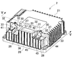
- FIG. 3 shows a perspective view of the electrical auxiliary storage device 2 according to the first embodiment of the present invention
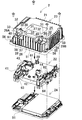
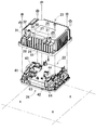
- FIG. 4 shows an exploded perspective view of the electrical auxiliary storage device 2.
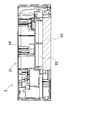
- FIG. 5 is a VV longitudinal sectional view of the electrical auxiliary storage device 2 shown in FIG. 3, and
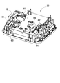
- FIG. 6 is a perspective view with the upper case 23 removed.
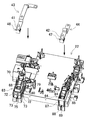
- FIG. 7 is an exploded perspective view showing an attachment procedure of the electrical equipment spare power storage device 2.
- FIG. 8 is a perspective view of a state where the positive and negative output terminals and the lead plate are removed.
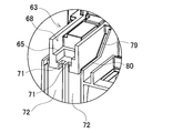
- FIG. 9 is a cross-sectional view of the support portion 63 on the positive output terminal 41 side.
- FIG. 10 is a cross-sectional view of the support portion 64 on the negative output terminal 42 side.
- the electrical auxiliary power storage device 2 includes a storage case 21 and a battery 22 stored in the storage case 21. (Storage case 3)
- the storage case 21 is formed of an insulating material such as plastic.
- the storage case 21 includes an upper case 23 and a lower case 24, and the upper case 23 is screwed to the lower case 24 while being covered with the lower case 24 so as to surround the lower case 24.
- the storage case 21 has a shape and a size capable of storing the battery 22 in a predetermined position.
- the storage case 21 has a non-waterproof structure.
- the non-waterproof structure means a structure that is not a completely waterproof structure that can completely prevent water from entering from the outside. Therefore, the non-waterproof storage case 21 includes a wide structure including a structure in which water from the outside does not easily enter in a normal use state, such as a structure in which an opening of a box-shaped case is closed with a lid. Use in meaning.
- Such a non-waterproof storage case 21 is characterized in that the structure can be simplified and the maintenance can be simplified while being manufactured at low cost.
- the upper case 23 is generally formed in a lid shape in which the lower part of the rectangular parallelepiped is opened, and two stepped portions 27 are provided at predetermined intervals at the corners connecting the upper surface 25 of the upper case 23 to the outer peripheral wall 26. ing.
- a stepped surface 28 that is the bottom surface of the stepped portion 27 is gently inclined downward toward the outside.
- Holes 29A and 29B are respectively formed in the stepped surface 28, and the positive output terminal 41 of the capacitor 22 protrudes from the hole 29A, and the negative output terminal 42 of the capacitor 22 protrudes from the hole 29B.
- a wall surface 30 rising toward the upper surface is formed at the peripheral edge of the holes 29A and 29B, and a mountain-shaped convex portion 31 is formed on the wall surface 30.
- the mountain-shaped convex portion 31 is a first guide means.
- the slope 32 forming the mountain shape of the convex portion 31 is formed symmetrically with respect to the positive and negative output terminals 41 and 42 protruding from the holes 29A and 29B, and the lower end of the slope 32 is formed on the side surface 33 in the vertical direction. It is connected.
- an inclined surface 37 inclined downward from the lower end of the convex portion 31 formed on the wall surface 30, and a continuous arrangement connected to the lower end of the inclined surface 37 are provided.
- the inclined surface 37 and the continuous surface 38 are second guide means.
- the inclined surface 37 and the continuous surface 38 are formed in a convex shape, and the lower ends of both side surfaces 33 of the convex portion 31 formed on the wall surface 30 are linear on the outer surface of the inclined surface 37 and the continuous surface 38. It is connected to the.
- a groove 45 along the length direction of the lead plate 44 is formed integrally with the peripheral edge of the hole 29B from which the negative output terminal 42 projects.
- the groove 45 is a second guide means.
- the groove 45 is linearly connected to the lower end of the side surface 33 of the convex portion 31 and is formed outward.
- Engaging portions 48 and 49 that engage with the throat portions 46 and 47 of the lead plates 43 and 44 are formed outside the holes 29A and 29B of the upper case 23, respectively.
- a fin 51 for releasing heat generated by the battery 22 to the outside is provided on the outer peripheral surface 26 of the upper case 23, and the upper case 23 is screwed to the lower case 24 at the lower end corner of the upper case 23.
- a hole 55 for fastening and a hole 56 for screwing the upper case 23 to the floor surface below the seat 13 of the cabin 12 are formed. (Accumulator 4)
- the capacitor 22 includes positive and negative connection terminals 61 and 62 on the upper surface side.
- One end of the lead plates 43 and 44 is connected to the positive and negative connection terminals 61 and 62, and the output terminals 41 and 42 are engaged with the other end of the lead plates 43 and 44.
- Support portions 63 and 64 for supporting the output terminals 41 and 42 engaged with the lead plates 43 and 44 are provided on the upper surface of the battery 22.
- the support portions 63 and 64 are formed in a convex shape on the upper surface of the battery 22, and the output terminals 41 and 42 engaged with the lead plates 43 and 44 are formed on the upper surfaces of the support portions 63 and 64 together with the lead plates 43 and 44.
- the openings 68 and 84 are fitted. At this time, the lower portions of the output terminals 41 and 42 are in contact with the stepped portions 65 and 67.
- the output terminal 41 is fitted into the opening 68 together with the lead plate 43.
- groove portions 70 having a U-shaped cross section are formed along both side surfaces of the lead plate 43, respectively.
- the groove portion 70 is gently inclined downward toward the outside of the battery 22.
- a hole 71 is formed below the lower end of the groove 70, and a space 72 having a rib at the center is formed below the hole 71.
- a hole 75 is formed in the bottom surface 73 of the space 72.
- an inclined groove 79 having a U-shaped section inclined downward along both sides of the lead plate 43 and a U-shaped section connected outward from the lower end of the inclined groove 79.
- a connecting groove 80 is formed. The lower end of the connecting groove 80 is connected to the space 72.
- the groove portion 70, the inclined groove 79, and the connecting groove 80 constitute third guide means.
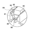
- the lead plate 44 with which the output terminal 42 is engaged protrudes upward from the opening 84, and in this state, the lead plate 44 is fitted into the hole 29 ⁇ / b> B of the upper case 23. It is.
- groove portions 85 having a U-shaped cross section are formed along both side surfaces of the lead plate 44.
- the groove 85 is gently inclined downward toward the outside of the battery 22.
- a hole 86 is formed below the lower end of the groove 85, and a space 87 is formed below the hole 86.
- a hole 89 is formed in the bottom surface 88 of the space 87.
- the groove portion 85 forms third guide means.
- (Lower case) 11 shows a drainage hole 92 on the positive output terminal 41 side formed in the lower case 24, and FIG. 12 shows a drainage hole 93 on the positive output terminal 42 side formed in the lower cover 24.
- FIG. 13 shows the inlet side of the drain holes 92 and 93.
- the lower case 24 is formed in a generally rectangular plate shape.
- the bottom wall 91 of the lower case 24, below the hole 75 on the positive output terminal 41 side and the hole 89 on the negative output terminal 42 side formed in the battery 22, respectively, 93 is formed.
- the waste liquid holes 92 and 93 have a quadrangular opening, and the inlet side opening of the waste liquid holes 92 and 93 located on the upper surface side of the bottom wall 91 has a U-shaped projection on three sides of the opening.
- a portion 94 is formed.
- screw holes for connecting and screwing the upper case 23 and the lower case 24 are provided at four corners of the lower case 24.
- the liquid droplet that has fallen on the upper surface 25 of the upper case 23 flows down along the wall surface 30
- the liquid droplet travels along the mountain-shaped slope 32 of the convex portion 31 formed on the wall surface 30, with respect to the positive and negative output terminals 41 and 42. And left and right.
- the liquid droplets distributed to the left and right of the convex portion 31 flow down along both side surfaces 33 of the convex portion 31.
- the liquid droplets that have flowed down along the both side surfaces 33 of the convex portion 31 are an inclined surface 37 formed on the stepped surface 28 and a continuous surface provided continuously at the lower end of the inclined surface 37. It flows along the outer edge with 38. Both side surfaces 33 of the convex portion 31 and the outer edge portions of the inclined surface 37 and the connecting surface 38 are connected to each other in a straight line, and the droplets are angled slopes 32 of the convex portion 31 formed on the wall surface 30. And it flows down smoothly along the outer edge part of the inclined surface 37 and the connection surface 38 which were formed in the side surface 33 and the stepped surface 28 further.
- the liquid droplets that have flowed down along both side surfaces 33 of the convex portion 31 flow into the groove 45 formed in the stepped surface 28.
- Both side surfaces 33 of the convex portion 31 and the groove portion 45 are linearly connected to each other, and the droplets are formed on the mountain-shaped slope 32 and both side surfaces 33 of the convex portion 31 formed on the wall surface 30 and further on the stepped surface 28. It smoothly flows down along the formed groove 45.
- liquid droplets that have flowed down to the positive and negative output terminals 41 and 42 along the upper surface of the upper case 23 are supplied from the holes 29A and 29B into which the positive and negative output terminals 41 and 42 are fitted. It is possible to effectively suppress the intrusion into the inside of the.
- liquid droplets may enter the inside of the storage case 21.
- the droplet may enter from the gap between the support portion 63 and the lead plate 43 fitted in the support portion 63.
- Droplet that has entered the inclined groove 79 or the continuous groove 80 falls into the space 72.
- the droplet that has fallen into the space 72 flows into the hole 75 and falls onto the bottom wall 91 of the lower case 24.
- the liquid droplets that have dropped onto the bottom wall 91 of the lower case 24 flow into the waste liquid holes 92 formed in the bottom wall 91 and are discharged to the outside of the electrical auxiliary storage device 2.
- the droplet When the droplet directly falls into the hole 29B in which the negative output terminal 42 is fitted, the droplet may enter from the gap between the opening end surface 98 of the hole 29B and the lead plate 44.
- the liquid droplets that have entered from the gap between the opening side end face 98 of the hole 29B and the lead plate 44 enter the groove 85 formed on the lower back side of the support opening 84.
- the droplet that has entered the groove 85 flows into the hole 86 and then falls into the space 87.
- the droplet that has fallen into the space 87 flows into the hole 89 and falls onto the bottom wall 91 of the lower case 24.
- the liquid droplets that have dropped onto the bottom wall 91 of the lower cover 24 flow into the waste liquid holes 93 formed in the bottom wall 91 and are discharged to the outside of the electrical auxiliary storage device 2.
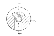
- FIG. 14 shows a state in which the droplet 95 enters the drain holes 92 and 93.
- the openings of the waste liquid holes 92 and 93 are rectangular, but in the upper surface side opening of the bottom wall 91 that is the inlet side of the waste liquid holes 92 and 93, three of the four sides of the opening are U-shaped. Covered with a convex portion 94. In this way, by preventing the openings on the inlet side of the waste liquid holes 92 and 93 from being flush with each other, it is possible to prevent the flow of droplets from stagnation at the inlets of the waste liquid holes 92 and 93.
- a mountain-shaped convex portion 31 is formed on the wall surface 30, and a droplet that has dropped on the upper surface 21 of the upper case 23 is positive or negative by the mountain-shaped convex portion 31.
- the present invention is not limited to this.
- a liquid droplet that has fallen on the upper surface 21 of the upper case 23 by a groove formed in the wall surface 30 is positive or negative.
- the output terminals 41 and 42 may be distributed to the left and right.
- the power supply device 100 mounted on the vehicle is charged and discharged by being connected to the generator 101 and the vehicle load 102 mounted on the vehicle as shown in FIG.
- the power supply device 100 shown in the figure is connected between the electrical spare battery device 2 and the electrical battery 1, and has a first switch 103 that connects the electrical spare battery device 2 in parallel to the electrical battery 1, and the electrical spare battery device And a second switch 104 that is connected to the output side 2 and prevents overcharging and overdischarging of the electrical auxiliary storage device 2.
- the connection state of the first switch 103 and the second switch 104 is controlled by the control circuit 105.
- the first switch 103 and the second switch 104 can use switching elements such as relays and semiconductor switching elements.
- the semiconductor switching element an element such as a transistor, an FET, or an IGBT can be used.
- the first switch 103 can be arranged in the engine room 11 or in the cabin 12.
- the second switch 104 is disposed in the storage case 21 of the auxiliary electrical storage device 2 and is connected between the output terminals 41 and 42 and the assembled battery.
- the generator 101 on the vehicle side prevents overcharging of the power supply device 100 by controlling the output voltage so that the charging voltage does not rise above the maximum voltage (for example, 14V to 15V) while the power supply device 100 is charged. ing.
- the control circuit 105 detects the remaining capacity of the electrical spare power storage device 2 and switches the second switch 1104 to OFF when the remaining capacity of the electrical spare power storage device 2 exceeds the maximum remaining capacity and is charged. The overpowering of the power storage device 2 is prevented and the electrical spare power storage device 2 is protected.
- the power supply device 100 shown in the figure supplies electric power to the electrical equipment 106 and the starter motor 107 and is discharged.
- the vehicle side charges the power supply device 100 by controlling the generator 101 so that the voltage of the power supply device 100 does not drop below the optimum voltage.
- the remaining capacity of the electrical auxiliary storage device 2 is detected by the control circuit 105, and when the remaining capacity is equal to or lower than the minimum remaining capacity, the control circuit 105
- the switch 104 is turned off to prevent overdischarge of the electrical auxiliary power storage device 2.
- the vehicle power supply device and the vehicle equipped with the power supply device according to the present invention can be suitably used as an electrical equipment battery or an auxiliary battery.
- the load of the lead battery can be reduced.
- DESCRIPTION OF SYMBOLS 100 Power supply device 101 ... Generator 102 ... Vehicle load 103 ... 1st switch 104 ... 2nd switch 105 ... Control circuit 106 ... Electrical equipment 107 ... Starter motor 1 ... Battery 1A for electrical equipment ... Lead battery 2 ... Preliminary electrical storage device 6 ... Lead wire 11 ... Engine room 12 ... Cabin 13 ... Seat 21 ... Storage case 22 ... Accumulator 23 ... Upper case 24 ... Lower case 25 ... Upper surface 26 ... Outer peripheral wall 27 ... Stepped portion 28 ... Stepped surfaces 29A, 29B, 55 56, 71, 75, 86, 89 ... hole 30 ... wall surface 31, 94 ... convex 32 ... slope 33 ...
Landscapes
- Chemical & Material Sciences (AREA)
- Chemical Kinetics & Catalysis (AREA)
- Electrochemistry (AREA)
- General Chemical & Material Sciences (AREA)
- Engineering & Computer Science (AREA)
- Manufacturing & Machinery (AREA)
- Sustainable Development (AREA)
- Life Sciences & Earth Sciences (AREA)
- Aviation & Aerospace Engineering (AREA)
- Sustainable Energy (AREA)
- Power Engineering (AREA)
- Transportation (AREA)
- Mechanical Engineering (AREA)
- Battery Mounting, Suspending (AREA)
- Electric Propulsion And Braking For Vehicles (AREA)
- Secondary Cells (AREA)
Abstract
Description
(電源装置100)
(電装用バッテリ1)
(電装予備蓄電装置2)
(収納ケース3)
上部ケース23は概ね直方体の下部が開口した蓋状に形成されており、上部ケース23の上面25から外周壁26に繋がる角部には段付き部27が所定の間隔を開けて2箇所設けられている。段付き部27の底面である段付き面28は、外方に向かって緩やかに下方傾斜している。段付き面28には孔部29A,29Bが各々形成されており、孔部29Aから蓄電器22の正の出力端子41が突出し、孔部29Bから蓄電器22の負の出力端子42が突出している。
孔部29A,29Bの周縁部には上面に向かって立ち上がる壁面30が形成されており、この壁面30には山形状の凸部31が形成されている。山形状の凸部31は第1のガイド手段である。凸部31の山形を形成する斜面32は、孔部29A,29Bから突出する正負の出力端子41,42に対して左右対称に形成されており、この斜面32の下端は上下方向の側面33に接続されている。
(蓄電器4)
図11は下部ケース24に形成される正の出力端子41側の排液孔92を示し、図12は下部カバー24に形成される正の出力端子42側の排液孔93を示す。図13は排液孔92,93の入口側を示す。下部ケース24は概ね四角形のプレート状に形成されている。下部ケース24の底壁91であって、蓄電器22に形成された正の出力端子41側の孔部75と、負の出力端子42側の孔部89との下方には、各々廃液孔92と93とが形成されている。廃液孔92,93は開口部が四角形に形成されており、底壁91の上面側に位置する廃液孔92,93の入口側開口部では、開口部の3辺に断面コの字状の凸部94が形成されている。なお、下部ケース24の4隅には上部ケース23と下部ケース24とを連結ねじ止めするためのねじ孔が設けられている。
101…発電機
102…車両負荷
103…第1スイッチ
104…第2スイッチ
105…制御回路
106…電装機器
107…スタータモータ
1…電装用バッテリ
1A…鉛バッテリ
2…電装予備蓄電装置
6…リード線
11…エンジンルーム
12…キャビン
13…座席
21…収納ケース
22…蓄電器
23…上部ケース
24…下部ケース
25…上面
26…外周壁
27…段付き部
28…段付き面
29A,29B,55,56,71,75,86,89…孔部
30…壁面
31,94…凸部
32…斜面
33…側面
37…傾斜面
38…連接面
41,42…出力端子
43,44…リード板
45,70,85…溝部
46,47…喉部
48,49…係合部
51…フィン
61,62…接続端子
63,64…支持部
65,67…段付き部
68,84…開口部
72,87…空間
73,88…底面
79…傾斜溝
80…連接溝
91…底壁
92,93…廃液孔
95…液滴
97,98…端面
Claims (10)
- 車両に装備される車両負荷に電力を供給する電装用バッテリに並列接続される車両用の電装予備蓄電装置であって、
出力端子を含む端子部分を有する蓄電部と、
前記蓄電部を収納する収納ケースとを備え、
前記収納ケースは、
前記蓄電部の端子部分が嵌め込まれる孔部と、
前記孔部の周縁部から立ち上がる壁面に設けられ、該壁面を伝って流れ落ちる液滴が孔部に浸入することを防止する第1のガイド手段と、
前記孔部の周縁部に設けられ、前記孔部の周縁部から液滴が孔部に浸入することを防止する第2のガイド手段とを有することを特徴とする車両用の電装予備蓄電装置。 - 前記第1のガイド手段は、前記壁面と共に山形状に一体成型された凸部であることを特徴とする請求項1に記載の車両用の電装予備蓄電装置。
- 前記第2のガイド手段は、前記孔部の周縁部に沿って一体成型された凸部であることを特徴とする請求項1又は2に記載の車両用の電装予備蓄電装置。
- 前記第2のガイド手段は、前記孔部の周縁部に沿って一体成型された溝部であることを特徴とする請求項1又は2に記載の車両用の電装予備蓄電装置。
- 車両用の電装予備蓄電装置はさらに、
前記孔部の下方に、該孔部から電源装置の内部に浸入した液滴を、収納ケース下部に形成された排液孔に導く第3のガイド手段を備えていることを特徴とする請求項1~4のいずれか1項に記載の車両用の電装予備蓄電装置。 - 前記第3のガイド手段は、前記孔部に設けられた下り勾配の溝部を備えていることを特徴とする請求項5に記載の車両用の電装予備蓄電装置。
- 前記排液孔の流入側開口部は、同一面上ではないことを特徴とする請求項5又は6に記載の車両用の電装予備蓄電装置。
- 前記収納ケースは上部ケースと下部ケースとで構成され、
前記上部ケースは前記下部ケースの周囲を包囲するように、該下部ケースに連結されてなることを特徴とする請求項1~7のいずれか1項に記載の車両用の電装予備蓄電装置。 - 前記蓄電部が、リチウムイオン二次電池又はニッケル水素電池であることを特徴とする請求項1~8のいずれか1項に記載の車両用の電装予備蓄電装置。
- 車両に装備される車両負荷に電力を供給する電装用バッテリに並列接続される車両用の電装予備蓄電装置を搭載する車両であって、
前記電装予備蓄電装置は蓄電部と前記蓄電部を収納する収納ケースとを備え、
前記収納ケースには、蓄電部の端子部分が嵌め込まれる孔部が形成されており、
前記孔部の周縁部から立ち上がる壁面には、壁面を伝って流れ落ちる液滴が孔部に浸入することを防止する第1のガイド手段が設けられ、
前記孔部の周縁部には前記孔部の周縁部から液滴が孔部に浸入することを防止する第2のガイド手段が設けられていることを特徴とする車両。
Priority Applications (3)
| Application Number | Priority Date | Filing Date | Title |
|---|---|---|---|
| CN201480025120.5A CN105164830B (zh) | 2013-06-28 | 2014-06-06 | 车载用电器辅助蓄电装置和具有该电器辅助蓄电装置的车辆 |
| JP2015523844A JP6333817B2 (ja) | 2013-06-28 | 2014-06-06 | 車載用の電装予備蓄電装置及びこの電装予備蓄電装置を備える車両 |
| US14/888,706 US9911964B2 (en) | 2013-06-28 | 2014-06-06 | Vehicle-mounted electrical equipment auxiliary electricity storage device and car equipped with electrical equipment auxiliary electricity storage device |
Applications Claiming Priority (2)
| Application Number | Priority Date | Filing Date | Title |
|---|---|---|---|
| JP2013-135935 | 2013-06-28 | ||
| JP2013135935 | 2013-06-28 |
Publications (1)
| Publication Number | Publication Date |
|---|---|
| WO2014208020A1 true WO2014208020A1 (ja) | 2014-12-31 |
Family
ID=52141395
Family Applications (1)
| Application Number | Title | Priority Date | Filing Date |
|---|---|---|---|
| PCT/JP2014/003034 Ceased WO2014208020A1 (ja) | 2013-06-28 | 2014-06-06 | 車載用の電装予備蓄電装置及びこの電装予備蓄電装置を備える車両 |
Country Status (4)
| Country | Link |
|---|---|
| US (1) | US9911964B2 (ja) |
| JP (1) | JP6333817B2 (ja) |
| CN (1) | CN105164830B (ja) |
| WO (1) | WO2014208020A1 (ja) |
Cited By (3)
| Publication number | Priority date | Publication date | Assignee | Title |
|---|---|---|---|---|
| WO2017073258A1 (ja) * | 2015-10-27 | 2017-05-04 | 株式会社オートネットワーク技術研究所 | 蓄電ユニット |
| JPWO2018110231A1 (ja) * | 2016-12-16 | 2019-10-24 | 三洋電機株式会社 | 防水構造のバッテリシステム |
| JP2020061234A (ja) * | 2018-10-08 | 2020-04-16 | 株式会社デンソー | 電池パック |
Families Citing this family (6)
| Publication number | Priority date | Publication date | Assignee | Title |
|---|---|---|---|---|
| JP6189318B2 (ja) * | 2012-10-29 | 2017-08-30 | 三洋電機株式会社 | 回生制動する車両の電源装置 |
| US9553288B2 (en) * | 2014-08-20 | 2017-01-24 | Ford Global Technologies, Llc | Step configuration for traction battery housing |
| JP6413637B2 (ja) * | 2014-10-30 | 2018-10-31 | 株式会社オートネットワーク技術研究所 | 蓄電ユニット |
| KR101823584B1 (ko) * | 2015-03-04 | 2018-01-30 | 주식회사 엘지화학 | 전지 팩 |
| CN110137391A (zh) * | 2018-02-08 | 2019-08-16 | 比亚迪股份有限公司 | 电池动力引出集成结构、电池包及车辆 |
| US10998595B2 (en) * | 2018-11-08 | 2021-05-04 | GM Global Technology Operations LLC | Modular vehicle battery |
Citations (4)
| Publication number | Priority date | Publication date | Assignee | Title |
|---|---|---|---|---|
| JPS62135354U (ja) * | 1986-02-19 | 1987-08-26 | ||
| JPH07232565A (ja) * | 1994-02-25 | 1995-09-05 | Nissan Motor Co Ltd | 電気自動車のバッテリフレーム構造 |
| WO2012133711A1 (ja) * | 2011-03-31 | 2012-10-04 | 三洋電機株式会社 | 電源装置の製造方法及び電源装置並びに電源装置を備える車両 |
| JP2012221738A (ja) * | 2011-04-08 | 2012-11-12 | Hitachi Vehicle Energy Ltd | 蓄電装置 |
Family Cites Families (7)
| Publication number | Priority date | Publication date | Assignee | Title |
|---|---|---|---|---|
| JP4432168B2 (ja) * | 1998-11-30 | 2010-03-17 | ソニー株式会社 | 移動体搭載用バッテリ装置 |
| JP4748010B2 (ja) | 2006-09-19 | 2011-08-17 | トヨタ自動車株式会社 | 電源装置 |
| EP2272722B1 (en) | 2009-07-01 | 2015-04-08 | Denso Corporation | Power source apparatus for vehicle |
| JP5471083B2 (ja) | 2009-07-01 | 2014-04-16 | 株式会社デンソー | 車載電源装置 |
| JP5452252B2 (ja) * | 2010-01-27 | 2014-03-26 | 三洋電機株式会社 | バッテリシステム |
| CN103201875B (zh) * | 2010-11-04 | 2015-11-25 | 株式会社牧田 | 电池组 |
| JP5683905B2 (ja) * | 2010-11-04 | 2015-03-11 | 株式会社マキタ | バッテリパック |
-
2014
- 2014-06-06 CN CN201480025120.5A patent/CN105164830B/zh active Active
- 2014-06-06 US US14/888,706 patent/US9911964B2/en active Active
- 2014-06-06 JP JP2015523844A patent/JP6333817B2/ja active Active
- 2014-06-06 WO PCT/JP2014/003034 patent/WO2014208020A1/ja not_active Ceased
Patent Citations (4)
| Publication number | Priority date | Publication date | Assignee | Title |
|---|---|---|---|---|
| JPS62135354U (ja) * | 1986-02-19 | 1987-08-26 | ||
| JPH07232565A (ja) * | 1994-02-25 | 1995-09-05 | Nissan Motor Co Ltd | 電気自動車のバッテリフレーム構造 |
| WO2012133711A1 (ja) * | 2011-03-31 | 2012-10-04 | 三洋電機株式会社 | 電源装置の製造方法及び電源装置並びに電源装置を備える車両 |
| JP2012221738A (ja) * | 2011-04-08 | 2012-11-12 | Hitachi Vehicle Energy Ltd | 蓄電装置 |
Cited By (8)
| Publication number | Priority date | Publication date | Assignee | Title |
|---|---|---|---|---|
| WO2017073258A1 (ja) * | 2015-10-27 | 2017-05-04 | 株式会社オートネットワーク技術研究所 | 蓄電ユニット |
| JPWO2017073258A1 (ja) * | 2015-10-27 | 2018-04-05 | 株式会社オートネットワーク技術研究所 | 蓄電ユニット |
| CN108140496A (zh) * | 2015-10-27 | 2018-06-08 | 株式会社自动网络技术研究所 | 蓄电单元 |
| CN108140496B (zh) * | 2015-10-27 | 2019-08-27 | 株式会社自动网络技术研究所 | 蓄电单元 |
| JPWO2018110231A1 (ja) * | 2016-12-16 | 2019-10-24 | 三洋電機株式会社 | 防水構造のバッテリシステム |
| US11404741B2 (en) | 2016-12-16 | 2022-08-02 | Sanyo Electric Co., Ltd. | Battery system having waterproof structure |
| JP2020061234A (ja) * | 2018-10-08 | 2020-04-16 | 株式会社デンソー | 電池パック |
| JP7099237B2 (ja) | 2018-10-08 | 2022-07-12 | 株式会社デンソー | 電池パック |
Also Published As
| Publication number | Publication date |
|---|---|
| US20160111702A1 (en) | 2016-04-21 |
| US9911964B2 (en) | 2018-03-06 |
| JP6333817B2 (ja) | 2018-05-30 |
| JPWO2014208020A1 (ja) | 2017-02-23 |
| CN105164830A (zh) | 2015-12-16 |
| CN105164830B (zh) | 2018-11-27 |
Similar Documents
| Publication | Publication Date | Title |
|---|---|---|
| JP6333817B2 (ja) | 車載用の電装予備蓄電装置及びこの電装予備蓄電装置を備える車両 | |
| JP5835246B2 (ja) | 電池ユニット | |
| JP5587167B2 (ja) | 電源装置及び電源装置を備える車両並びに防塵ケース | |
| JP5880473B2 (ja) | 電池ユニット | |
| US8294293B2 (en) | High-voltage electrical component unit for vehicles | |
| JP5592194B2 (ja) | 電池パック | |
| JP6124292B2 (ja) | 車載用の電源装置及び電源装置を備える車両 | |
| JP5474499B2 (ja) | 車両用の電源装置及びこの電源装置を搭載する車両 | |
| JP5835247B2 (ja) | 電池ユニット | |
| US10090495B2 (en) | Electricity storage device | |
| JPWO2014068882A1 (ja) | 車載用の電装予備バッテリユニットと車両用の電源装置及びこの電源装置を搭載する車両 | |
| US20160093857A1 (en) | Battery module vent system and method | |
| US11545820B2 (en) | Electrical connection box | |
| JPWO2014068922A1 (ja) | 車載用の電源装置及び電源装置を備える車両 | |
| WO2013187280A1 (ja) | 車載用の電装用バッテリ | |
| JP2014088068A (ja) | 車載用の電装予備蓄電部とこの電装予備蓄電部を搭載する車両 | |
| WO2016053416A1 (en) | Battery module water management features | |
| JPWO2014068897A1 (ja) | 電源装置及び電源装置を備える車両並びに蓄電装置、バッテリシステム | |
| JP2015011849A (ja) | 補助バッテリを備えるバッテリ | |
| EP4050713A1 (en) | Power supply device, electric vehicle using same, and power storage device | |
| JP2012221738A (ja) | 蓄電装置 | |
| JPWO2014068899A1 (ja) | 電源装置及び電源装置を備える車両並びに蓄電装置、バッテリシステム | |
| JP2015011844A (ja) | 車載用の電源装置及び電源装置を備える車両並びにバスバー | |
| US11038245B2 (en) | Battery wiring module | |
| KR20230058872A (ko) | 내충격성이 향상된 전지팩 케이스 및 이를 포함하는 전지팩 |
Legal Events
| Date | Code | Title | Description |
|---|---|---|---|
| WWE | Wipo information: entry into national phase |
Ref document number: 201480025120.5 Country of ref document: CN |
|
| 121 | Ep: the epo has been informed by wipo that ep was designated in this application |
Ref document number: 14818141 Country of ref document: EP Kind code of ref document: A1 |
|
| WWE | Wipo information: entry into national phase |
Ref document number: 14888706 Country of ref document: US |
|
| ENP | Entry into the national phase |
Ref document number: 2015523844 Country of ref document: JP Kind code of ref document: A |
|
| NENP | Non-entry into the national phase |
Ref country code: DE |
|
| 122 | Ep: pct application non-entry in european phase |
Ref document number: 14818141 Country of ref document: EP Kind code of ref document: A1 |