WO2014207876A1 - 画像形成装置及びプロセスカートリッジ - Google Patents
画像形成装置及びプロセスカートリッジ Download PDFInfo
- Publication number
- WO2014207876A1 WO2014207876A1 PCT/JP2013/067722 JP2013067722W WO2014207876A1 WO 2014207876 A1 WO2014207876 A1 WO 2014207876A1 JP 2013067722 W JP2013067722 W JP 2013067722W WO 2014207876 A1 WO2014207876 A1 WO 2014207876A1
- Authority
- WO
- WIPO (PCT)
- Prior art keywords
- particles
- toner
- resin
- mass
- fine particles
- Prior art date
- Legal status (The legal status is an assumption and is not a legal conclusion. Google has not performed a legal analysis and makes no representation as to the accuracy of the status listed.)
- Ceased
Links
Images







Classifications
-
- G—PHYSICS
- G03—PHOTOGRAPHY; CINEMATOGRAPHY; ANALOGOUS TECHNIQUES USING WAVES OTHER THAN OPTICAL WAVES; ELECTROGRAPHY; HOLOGRAPHY
- G03G—ELECTROGRAPHY; ELECTROPHOTOGRAPHY; MAGNETOGRAPHY
- G03G15/00—Apparatus for electrographic processes using a charge pattern
- G03G15/02—Apparatus for electrographic processes using a charge pattern for laying down a uniform charge, e.g. for sensitising; Corona discharge devices
- G03G15/0208—Apparatus for electrographic processes using a charge pattern for laying down a uniform charge, e.g. for sensitising; Corona discharge devices by contact, friction or induction, e.g. liquid charging apparatus
- G03G15/0216—Apparatus for electrographic processes using a charge pattern for laying down a uniform charge, e.g. for sensitising; Corona discharge devices by contact, friction or induction, e.g. liquid charging apparatus by bringing a charging member into contact with the member to be charged, e.g. roller, brush chargers
- G03G15/0233—Structure, details of the charging member, e.g. chemical composition, surface properties
Definitions
- the present invention relates to an image forming apparatus and a process cartridge.
- An image forming apparatus employing an electrophotographic system mainly includes an electrophotographic photosensitive member, a charging device, an exposure device, a developing device, a transfer device, a cleaning device, and a fixing device.
- the charging device applies a voltage (a voltage of only a DC voltage or a voltage obtained by superimposing an AC voltage on a DC voltage) to a charging member that is in contact with or close to the surface of an electrophotographic photosensitive member (hereinafter also referred to as “photosensitive member”).
- a method of charging the surface of the photoreceptor is employed.
- a contact-type charging method is preferably used.
- a roller-shaped charging member is preferably used.
- Patent Document 1 or 2 discloses a technique for forming a surface layer having a convex portion derived from resin particles or the like on the surface of a charging member. As described in Patent Document 3, these techniques are presumed to improve charging uniformity by performing in-nip discharge near the convex portion. Thereby, it is possible to suppress the occurrence of a horizontal streak-like image (hereinafter referred to as “horizontal streak-like image”) due to non-uniformity of the electrical resistance value.
- horizontal streak-like image hereinafter referred to as “horizontal streak-like image”
- Patent Document 1 or 2 does not describe a solution to this problem.
- image forming apparatuses are required to have higher speeds, and at the same time, the use environments of the image forming apparatuses are diverse.
- An object of the present invention is to suppress the occurrence of horizontal streak-like images caused by a decrease in discharge intensity in the nip in a charging member of an image forming apparatus, and at the same time, An object of the present invention is to provide a charging member in which generation is suppressed.
- Another object of the present invention is to provide a process cartridge and an image forming apparatus using the charging member.
- the present invention relates to a photoconductor, a charging unit for charging the photoconductor with a charging member, an exposure unit for forming an electrostatic latent image on the surface of the charged photoconductor, and an electrostatic latent image.
- An image forming apparatus having a developing unit for supplying toner to the formed photoreceptor to form a toner image on the surface of the photoreceptor,
- the charging member is a charging member having a conductive substrate and a conductive resin layer,
- the resin layer includes a binder resin C and resin particles that roughen the surface of the charging member, and the inside of the resin particles has a plurality of pores,
- the surface of the charging member has a plurality of convex portions derived from the resin particles,
- the toner is a toner containing toner particles containing a binder resin T and a colorant, and inorganic fine particles,
- the inorganic fine particles are silica fine particles;
- the toner contains 0.40 parts by mass or
- the silica fine particles are treated with 15.0 parts by mass or more and 40.0 parts by mass or less of silicone oil with respect to 100 parts by mass of the silica raw material, and the carbon oil-based immobilization ratio (%) of the silicone oil. Is over 70%,
- the coverage X1 with the silica fine particles on the toner surface determined by an X-ray photoelectron spectrometer (ESCA) is 50.0 area% or more and 75.0 area% or less, and the theoretical coverage with the silica fine particles is X2.
- the present invention it is possible to suppress the occurrence of a horizontal streak-like image due to a decrease in the discharge intensity in the nip, and at the same time, to suppress the occurrence of a spot-like image due to abnormal discharge due to contamination of the surface of the charging member. it can.
- FIG. 4 is a diagram illustrating a boundary line of a diffusion index of toner according to the present invention.
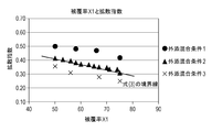
- FIG. 5 is a graph plotting a coverage ratio X1 and a diffusion index of toner according to the present invention. It is a three-dimensional schematic diagram of resin particles that form convex portions on the surface of the charging member.
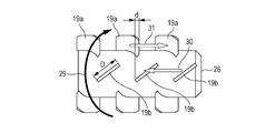
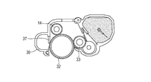
- FIG. 3 is a schematic diagram illustrating a contact state between a charging member and a photosensitive member according to the present invention. It is the schematic of one aspect
- the present inventors examined the contact state and the discharge state when the charging members described in Patent Documents 1 and 2 charge the photoreceptor.
- the nip portion between the charging member and the photosensitive member was observed in detail.
- the contact between the photosensitive member and the charging member is limited to a narrow range near the top of the convex portion.
- the contact portion near the top of the convex portion was found that slip occurred. Further, it has been found that vibration is generated by the slip and is transmitted to the photosensitive member.
- the vibration generated by the slip causes the photoreceptor to vibrate. Then, it has been found that the toner remaining on the surface of the photoconductor after the transfer process passes through the cleaning member through a minute gap generated by vibration of the photoconductor in the cleaning process. Further, it has been found that when toner having a more spherical shape is used, toner slippage becomes remarkable. At the same time, it has also been found that the toner slip easily occurs at a portion where the aggregated residual toner collides with the cleaning member.
- the present inventors have studied to suppress the occurrence of the slip while maintaining the discharge in the nip.
- the process it is found that if a plurality of holes are formed inside the resin particles forming the convex part, the convex part is easily deformed and the contact area between the convex part of the charging member and the photosensitive member is enlarged. It was. The larger the porosity of the resin particles, the greater the deformation of the convex portion, and the contact area can be expanded. This leads to relaxation of pressure concentration in the vicinity of the top of the convex portion, and enables suppression of the slip. It has also been found that the deformation of the convex part absorbs the vibration of the photosensitive member and stabilizes the rotation of the photosensitive member.
- the present inventors diligently studied the generation mechanism of the charging member slip, the removal of toner from the cleaning member, and the charging member contamination in the image forming apparatus or process cartridge using the charging member and toner.
- the present inventors based on the results of studies using a roll-shaped charging member and a blade-shaped cleaning member, a detailed description will be given below.
- the present inventors charged the photosensitive member using the charging member of Patent Document 1 as a charging member, and observed the behavior of the surface of the cleaning member when no residual toner was present. As the rotation speed of the photosensitive member increased, slipping of the charging member was confirmed as described above. As a result, it was also confirmed that vibration due to slipping of the charging member was transmitted to the photoconductor, and that a fine gap was generated between the cleaning member and the photoconductor.
- the present inventors prepared a toner that has undergone a transfer process by using an image forming apparatus using a conventional toner. That is, the above toner is separately prepared as an aggregate toner that simulates the residual toner (hereinafter also referred to as “aggregate toner”). Then, the agglomerated toner was supplied to the cleaning member in contact with the photoconductor rotated at a high speed. As a result, at the contact portion between the cleaning member and the photosensitive member, the toner significantly slipped from the portion where the aggregated toner collided with the cleaning member as described above, and it was confirmed that the toner adhered to the charging member.
- the charging member according to the present invention was used in place of the conventional charging member, and the charging member was first observed in the absence of the agglomerated toner.
- the charging member slip observed with the conventional charging member could not be confirmed.
- the rotation of the photosensitive member was stabilized.
- the agglomerated toner is supplied to the cleaning member in the same manner as described above, there is no generation of toner that passes through immediately after the supply, but after a while after supply, toner that passes through is generated and does not adhere to the surface of the charging member. Toner adhesion has occurred.
- the aggregated toner that has been removed often remains on the surface of the cleaning member, and the aggregated toners coming from one to the next repeatedly accumulate and reaggregate near the surface of the cleaning member.
- the accumulated and re-aggregated toner further increases the adhesive force with the surface of the photoreceptor.
- the accumulated and re-aggregated toner gives an impact to the cleaning member, and it is presumed that the toner adheres to the charging member due to toner slipping.
- the present inventors used the toner according to the present invention and conducted the same examination as described above.
- the residual toner was simulated and reproduced, but the toner according to the present invention hardly forms the aggregation toner on the surface of the photoreceptor even after the transfer process. all right.
- the photosensitive member was rotated at high speed while being charged by the charging member according to the present invention.
- the toner according to the present invention after the transfer process was supplied to the cleaning member.
- the photosensitive member was rotated at high speed, and the toner according to the present invention after the transfer process was supplied to the cleaning member.
- the toner passing through the cleaning member was slightly observed, the toner hardly adhered to the charging member, and the toner was hardly adhered.
- the inventors presume the mechanism that can suppress the contamination of the surface of the charging member by using the charging member according to the present invention and the toner according to the present invention as follows.
- the charging member according to the present invention controls the pores of the resin particles forming convex portions on the surface. As a result, the deformability of the convex portion is controlled, and the slip with the photoconductor is suppressed while maintaining the discharge in the nip.
- the toner according to the present invention controls the state of silica fine particles on the surface of the toner in detail, and greatly reduces the cohesiveness between the toners. As a result, the generation of aggregated toner after the transfer process and the accumulation / reaggregation of toner near the surface of the cleaning member are greatly reduced.
- the toner according to the present invention is used, even if the toner slipped out from the cleaning member is generated, the slipped toner does not aggregate and tends to exist in a scattered state.
- the pressure applied to each slipped toner is reduced, and adhesion to the surface of the charging member is greatly suppressed.
- the deformation and restoration of the convex portion makes it possible to push the toner back into the photosensitive member without rubbing the toner in contact with the charging member, and it is assumed that the toner adheres to and adheres to the surface of the charging member. ing.
- the synergistic effect using the charging member and the toner according to the present invention together prevents the toner from slipping out of the cleaning member, and suppresses toner adhesion and contamination on the surface of the charging member. .
- the charging member according to the present invention only needs to have the conductive base and a conductive resin layer, and the shape thereof may be any of a roller shape, a flat plate shape, and the like.
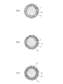
- FIG. 1 (1 a) shows an example of a cross section of a charging member according to the present invention, which has a conductive substrate 1 and a conductive resin layer 2 covering the peripheral surface thereof.
- the conductive resin layer 2 contains resin particles 3.
- one or more conductive elastic layers 4 may be provided between the conductive substrate 1 and the conductive resin layer 2.
- the conductive elastic layer 4 may be bonded via a conductive adhesive 5.
- the conductive elastic layer 4 and the conductive resin layer 2 shown in FIG. 1 (1b) may be bonded via a conductive adhesive.
- a known binder resin and conductive agent can be used for the adhesive.
- examples of the binder resin for the adhesive include a thermosetting resin and a thermoplastic resin, and known urethane, acrylic, polyester, polyether, and epoxy resins can be used.
- a conductive agent for imparting conductivity to the adhesive it can be appropriately selected from conductive particles and ionic conductive agents, and can be used alone or in combination of two or more.
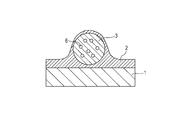
- FIG. 2 is a schematic sectional view of the conductive resin layer 2 forming the surfaces of the conductive substrate 1 and the charging member.
- the resin layer 2 includes a binder resin, conductive particles dispersed in the binder resin, and resin particles 3 for roughening the resin layer 2, and the resin layer 2 has a surface on the surface of the resin layer 2.
- a plurality of convex portions derived from the particles 3 are provided.
- the resin particles 3 forming the convex portions are characterized by having a plurality of holes 6 inside.
- the binder resin contained in the resin layer of the charging member is also referred to as a binder resin C.
- the charging member according to the present invention is in contact with the photosensitive member in the vicinity of the vertex of the convex portion, and has a gap in a portion other than the convex portion. And in the said space
- the vibration of the charging member due to the slip is suppressed, and further, the vibration of the photosensitive member is absorbed to prevent a gap between the cleaning member and the photosensitive member, thereby preventing the residual toner from slipping through. Then, the rubbing of the toner that has passed through the cleaning member due to the slip of the charging member is suppressed.
- the present inventors infer that the occurrence of the horizontal streak-like image and the point-like image can be suppressed by these effects.
- the porosity of the entire resin particles forming the convex portions is preferably 2.5% by volume or less.
- a more preferable range is 0.5 volume% or more and 2.0 volume% or less. This makes it possible to maintain the nip discharge more effectively.
- the plurality of pores in the resin particles forming the convex portions have a porosity on the resin particle convex portion apex side (hereinafter, this porosity is also referred to as “porosity V 11 ”). It is preferable that it is 5 volume% or more and 20 volume% or less. A more preferred range of porosity V 11, 5.5% by volume or more and 15% by volume or less. By the value of the porosity V 11 within the range, it is possible to achieve both more effectively the nip discharge and slip suppression. Details will be described later.
- Binder Resin C As the binder resin C used for the conductive resin layer, a known rubber or resin can be used. Examples of rubber include natural rubber, a vulcanized product thereof, and synthetic rubber.
- Synthetic rubbers include ethylene propylene rubber, styrene butadiene rubber (SBR), silicone rubber, urethane rubber, isoprene rubber (IR), butyl rubber, acrylonitrile butadiene rubber (NBR), chloroprene rubber (CR), acrylic rubber, epichlorohydrin rubber and fluorine. Rubber can be used.
- a resin such as a thermosetting resin or a thermoplastic resin
- fluorine resin, polyamide resin, acrylic resin, polyurethane resin, acrylic urethane resin, silicone resin, and butyral resin are more preferable.
- acrylic resins, polyurethane resins, and acrylic urethane resins are particularly preferred.
- a polyurethane resin is preferably used because it can easily form an aggregate having the above conductive particles and inorganic particles and can easily adjust the median diameter (D50 particle diameter) of the aggregate. These may be used alone or in combination of two or more.
- binder resins may be formed by adding a crosslinking agent to a prepolymerized binder resin material and curing or crosslinking.
- the above mixture will also be described below as a binder resin.
- the polyurethane resin can be obtained by a reaction between a known polyol and an isocyanate compound.
- examples of the polyol include lactone-modified acrylic polyol, polyethylene glycol, polypropylene glycol, and polytetramethylene glycol.
- an isocyanate compound made to react with these polyol components it has a cyclic structure from a viewpoint of formation of the electroconductive particle mentioned above or the aggregate which has electroconductive particle, and an inorganic particle, and its stability. It is preferable. Specifically, it is preferable to use alicyclic isocyanate or aromatic isocyanate.
- the alicyclic isocyanate include isophorone diisocyanate (IPDI), cyclohexane 1,3-diisocyanate, and cyclohexane 1,4-diisocyanate.
- the aromatic isocyanate include 2,4-tolylene diisocyanate, 2,6-tolylene diisocyanate (TDI), and diphenylmethane diisocyanate (MDI).
- an aliphatic isocyanate in combination with the above isocyanate.
- the deformation of the charging member due to contact with the photoreceptor is repeated for image formation, the deformation causes re-dispersion / re-aggregation of the conductive particles or the aggregates having the conductive particles and the inorganic particles. Suppresses the occurrence of abnormal discharge. Therefore, stable discharge can be performed over a long period of time.
- the aliphatic polyisocyanate include ethylene diisocyanate and 1,6-hexamethylene diisocyanate (HDI).
- the isocyanate used in the present invention a derivative that is a modified or copolymerized product of these can be used.
- an isocyanurate-type trimer is more preferable.
- the rigid trimer of the molecule serves as a crosslinking point, the resin layer can be crosslinked more densely, and the stability of the aggregate having conductive particles and inorganic particles can be further effectively improved.
- the isocyanate used in the present invention is more preferably a blocked isocyanate in which an isocyanate group is blocked with a blocking agent. This is because the isocyanate group easily reacts, and if the coating solution for forming a resin layer is left for a long time, the reaction gradually proceeds and the characteristics of the coating solution may change.
- the blocked isocyanate has an advantage that the active isocyanate group is blocked and does not react up to the dissociation temperature of the blocking agent, so that the coating liquid can be easily handled.
- the blocking agent for performing masking include phenols such as phenol and cresol, lactams of ⁇ -caprolactam, and oximes such as methyl ethyl ketoxime. In the present invention, oximes having a relatively low dissociation temperature are preferred.
- the polyurethane resin is obtained by a reaction between a polyol and an isocyanate compound
- the dispersion of the conductive particles can be stabilized.
- inorganic particles it becomes easy to form an aggregate in which conductive particles and inorganic particles are uniformly mixed. As a result, it is possible to perform stable nip discharge over a long period of time.
- Examples of the material of the resin particles contained in the conductive resin layer include particles made of the following polymer compounds.
- the binder resin C since it is easy to disperse in the binder resin C, it is preferable to be composed of the above-described polymer compound. Furthermore, when a convex portion is formed on the surface of the charging member, an acrylic resin, a styrene resin, a gap for generating an in-nip discharge between the photosensitive member and the photosensitive member is easily maintained in all environments. It is more preferable to use a styrene acrylic resin.
- Resin particles may be used alone or in combination of two or more, and may be subjected to surface treatment, modification, introduction of functional groups or molecular chains, and coating.
- the content of the resin particles in the resin layer is preferably 2 parts by mass or more and 100 parts by mass or less, and more preferably 5 parts by mass or more and 80 parts by mass or less with respect to 100 parts by mass of the binder resin C. By setting it as this range, the said in-nip discharge can be generated more stably.
- the volume average particle size of the resin particles is preferably 10 ⁇ m or more and 50 ⁇ m or less. By setting it as this range, the said in-nip discharge can be generated more stably.
- the resin particles contained in the resin layer have a plurality of pores inside, they are porous resin particles (hereinafter referred to as “porous particles”) or multi-hollow resin particles (hereinafter “multi-hollow”). Called “particles”).
- the resin particles in the resin layer preferably have a porosity of 2.5% by volume or less as described above, as described above.
- a more preferable range is 0.5 volume% or more and 2.0 volume% or less. By setting it within this range, it becomes possible to suppress the occurrence of the slip while more effectively maintaining the discharge in the nip.
- the resin particles contained in the resin layer are in a state where the pores in the inner region of the resin particles are concentrated in the region near the surface of the resin particle. That is, it is preferable to have a core-shell structure in which the porosity in the region near the surface of the resin particle is larger than the porosity in the inner region of the resin particle. In the above particles, it is preferable to control the porosity of the inner region to 5 volume% or more and 35 volume% or less, and the average pore diameter of the inner region to 10 nm or more and 45 nm or less.
- the porosity in the vicinity of the surface area is 10% by volume to 55% by volume
- the average pore diameter in the near-surface area (hereinafter, this average pore diameter is also referred to as “average pore diameter R 11 ”) is in the range of 30 nm to 200 nm. The following is preferable.
- average pore size R 11 in this range, it becomes easy and controls the porosity of the surface protrusion near the apex of the charging member described above more easily.
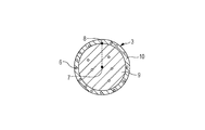
- the porous particle which has a core shell structure used for the porosity control of this invention is demonstrated using FIG.
- the center 7 of the resin particle 3 when the resin particle 3 is assumed to be a solid particle is calculated.
- a position moved by (3) 1/2 / 2 times the particle radius from the center 7 to the outside of the particle, for example, 8 is calculated.
- 100 points are calculated in the same manner as 8 so that the particles are evenly arranged with respect to the outer periphery of the particle, and a region connecting these points with a straight line is calculated.
- the internal region is defined as the region on the particle center 7 side of the region connecting these points, that is, the region 9 and the near-surface region is a position moved by (3) 1/2 / 2 times the radius. It is defined as an area outside 8, that is, 10 areas. The method of each parameter will be described in detail later.
- porous particles as resin particles as a raw material before inclusion in the resin layer.
- the use of such porous particles makes it possible to easily control the porosity described above with respect to the resin particles forming the convex portions on the surface of the charging member.
- the porous particle is defined as a particle having a large number of pores penetrating the surface of the resin particle.
- the multi-hollow particle is defined as a particle having a plurality of pores having a region containing air inside, and the pores are particles that do not penetrate the surface of the resin particle.
- porous particles examples include acrylic resin, styrene resin, acrylonitrile resin, vinylidene chloride resin, and vinyl chloride resin. These resins can be used alone or in combination of two or more. Furthermore, monomers used as raw materials for these resins may be copolymerized and used as a copolymer. You may contain other well-known resin as needed for these resins as a main component.
- the porous particles can be prepared by suspension polymerization, interfacial polymerization, interfacial precipitation, in-liquid drying, or a known production method in which a solute or solvent that lowers the solubility of the resin is added to the resin solution to cause precipitation.
- a porous agent is dissolved in a polymerizable monomer in the presence of a crosslinkable monomer to prepare an oily mixed solution.
- aqueous suspension polymerization is carried out in an aqueous medium containing a surfactant and a dispersion stabilizer, and after completion of the polymerization, washing and drying steps are performed to remove water and the porosifying agent, and resin particles Can be obtained.
- a compound having a reactive group that reacts with the functional group of the polymerizable monomer, or an organic filler can also be added.
- polymerization monomer examples include the following. Styrene monomers such as styrene, p-methylstyrene, p-tert-butylstyrene; methyl acrylate, ethyl acrylate, propyl acrylate, butyl acrylate, 2-ethylhexyl acrylate, lauryl acrylate, methyl methacrylate, methacryl Ethyl acetate, propyl methacrylate, butyl methacrylate, isobutyl methacrylate, tert-butyl methacrylate, benzyl methacrylate, phenyl methacrylate, isobornyl methacrylate, cyclohexyl methacrylate, glycidyl methacrylate, hydrofurfuryl methacrylate, lauryl methacrylate (Meth) acrylic acid ester monomers such as These polymerization monomers may be used alone or in combination of two or more.
- the crosslinkable monomer is not particularly limited as long as it has a plurality of vinyl groups, and the following can be exemplified.
- the crosslinkable monomer is preferably used so as to be 5% by mass or more and 90% by mass in the monomer. By setting it within this range, it becomes possible to reliably form pores inside the porous particles.
- a non-polymerizable solvent a mixture of a linear polymer and a non-polymerizable solvent dissolved in a mixture of polymerizable monomers, or a cellulose resin
- the following can be illustrated as a non-polymerizable solvent.
- Ethyl cellulose can be mentioned.
- These porous agents can be used alone or in combination of two or more. The addition amount of the porosifying agent can be appropriately selected according to the purpose of use.
- the oil phase composed of the polymerization monomer, the crosslinkable monomer and the porosizing agent from 20 parts by mass. It is preferable to use in the range of 90 parts by mass. By setting it within this range, the porous particles are not easily fragile, and a gap is easily formed in the nip between the charging member and the photosensitive member.
- the polymerization initiator is not particularly limited, but is preferably soluble in the polymerizable monomer.
- Known peroxide initiators and azo initiators can be used, and the following can be exemplified. 2,2'-azobisisobutyronitrile, 1,1'-azobiscyclohexane 1-carbonitrile, 2,2'-azobis-4-methoxy-2,4-dimethylvaleronitrile and 2,2'-azobis -2,4-Dimethylvaleronitrile.
- surfactants include the following.
- Anionic surfactants such as sodium lauryl sulfate, polyoxyethylene (degree of polymerization 1 to 100), sodium lauryl sulfate, polyoxyethylene (degree of polymerization 1 to 100), triethanolamine lauryl sulfate; stearyltrimethylammonium chloride, stearic acid Cationic surfactants such as diethylaminoethylamide lactate, dilaurylamine hydrochloride, oleylamine lactate; adipic acid diethanolamine condensate, lauryldimethylamine oxide, glyceryl monostearate, sorbitan monolaurate, diethylaminoethylamide stearate
- Nonionic surfactants such as: palm oil fatty acid amidopropyl dimethylaminoacetic acid betaine, lauryl hydroxysulfobetaine, sodium ⁇ -laurylaminopropionate It can amphoteric surfact
- Organic fine particles such as polystyrene fine particles, polymethyl methacrylate fine particles, polyacrylic acid fine particles, and polyepoxide fine particles; silica such as colloidal silica; calcium carbonate, calcium phosphate, aluminum hydroxide, barium carbonate, and magnesium hydroxide.
- Suspension polymerization is preferably carried out in a sealed manner using a pressure vessel, and the raw material components may be suspended in a disperser or the like before polymerization and then transferred to the pressure vessel for suspension polymerization. It may be suspended.
- the polymerization temperature is more preferably 50 ° C to 120 ° C.
- the polymerization may be carried out under atmospheric pressure, but is preferably carried out under pressure (under a pressure obtained by adding 0.1 to 1 MPa to atmospheric pressure) so as not to make the porous agent gaseous. After completion of the polymerization, solid-liquid separation and washing may be performed by centrifugation or filtration.
- drying or pulverization may be performed at a temperature equal to or lower than the softening temperature of the resin constituting the resin particles. Drying and pulverization can be performed by a known method, and an air dryer, a normal air dryer, and a Nauta mixer can be used. Further, drying and pulverization can be simultaneously performed by a pulverization dryer. Surfactants and dispersion stabilizers can be removed by repeating washing filtration after production.
- the particle size of the resin particles depends on the mixing conditions of the oil-based liquid mixture composed of a polymerizable monomer and a porosifying agent and an aqueous medium containing a surfactant and a dispersion stabilizer, the amount of dispersion stabilizer added, and the stirring and dispersing conditions. Can be adjusted. By increasing the addition amount of the dispersion stabilizer, the average particle diameter can be lowered. Moreover, it is possible to reduce the average particle diameter of the porous particles by increasing the stirring speed under stirring dispersion conditions.
- the volume average particle size of the porous particles is preferably in the range of 5 to 60 ⁇ m. More preferably, it is in the range of 10 to 50 ⁇ m. By setting it within this range, the discharge in the nip can be generated more stably.
- the porosity and pore diameter of the porous particles can be adjusted by the addition amount of the crosslinkable monomer, the kind and addition amount of the porous agent.
- the porosity and the pore diameter can be adjusted by increasing / decreasing the amount of the porous agent added to the polymerization monomer. Moreover, it can adjust also by increase / decrease in the addition amount of a crosslinkable monomer.
- the direction of increasing the amount of the porous agent and decreasing the addition amount of the crosslinkable monomer is the direction of increasing the porosity and the pore diameter.
- the pore diameter when the pore diameter is further increased, it can be achieved by using a cellulose resin as a porous agent.
- the pore diameter of the porous particles is preferably 10 to 500 nm and within 20% or less of the average particle diameter of the resin particles. Further, it is more preferably 20 to 200 nm and within a range of 10% or less with respect to the average particle diameter of the resin particles. By making it within this range, it becomes easy to adjust the pores to the above preferred range when forming the convex portion on the surface of the charging member.
- the porous particles preferably have a core-shell structure in which the porosity in the region near the surface of the particles is larger than the porosity in the inner region of the particles.
- Such porous particles having a porosity in the region near the surface larger than the porosity in the internal region can be produced using two types of porosifying agents.
- porous particles having such a core-shell structure when forming convex portions on the surface of the charging member, vacancies are concentrated in the region on the apex side of the convex portions of the resin particles. Easy to do. In this state, the slip suppression effect between the photosensitive member and the charging member can be effectively exhibited without weakening the discharge in the nip.
- Porous particles having different structures in the interior and in the vicinity of the surface should be prepared by using two kinds of porosifying agents having different solubility parameters (hereinafter referred to as “SP values”) as porosifying agents. Can do.
- SP values solubility parameters
- the case where normal hexane and ethyl acetate are used as the porosifying agent will be described below as an example.
- porosifying agents when an oily mixed liquid obtained by mixing a polymerizable monomer and a porosifying agent is added to an aqueous medium, ethyl acetate having an SP value close to the medium and the water used is A large amount will be present on the aqueous medium side, that is, outside the suspension droplets.
- more normal hexane is present inside the droplet.
- ethyl acetate existing outside the droplet has an SP value close to that of water, a certain amount of water is dissolved in ethyl acetate.
- the solubility of the porous agent in the polymerizable monomer is reduced in the outer portion of the droplet compared to the inner portion of the droplet, and the polymerizable monomer and the porous agent are separated from each other compared to the inner portion. It is easy to do. In other words, outside the droplets, the porosifying agent tends to exist in a larger mass than the inside.
- the pore diameter in the vicinity of the surface of the porous particles can be increased, and the pores can be obtained.
- the rate can be increased.
- Preferred examples of the porosifying agent used in the above means include ethyl acetate, methyl acetate, propyl acetate, isopropyl acetate, butyl acetate, acetone, and methyl ethyl ketone.
- Preferred examples of the porosifying agent used in the above means include normal hexane, normal octane, and normal dodecane.
- the porosizing agent having an SP value closer to water is preferably 30 parts by mass or less with respect to 100 parts by mass of the entire porosizing agent. More preferably, it is in the range of 15 to 25 parts by mass.
- Multi hollow particles examples of the material of the multi-hollow particles include the same resins as the porous particles. These resins can be used alone or in combination of two or more. Furthermore, monomers used as raw materials for these resins may be copolymerized and used as a copolymer. You may contain other well-known resin as needed for these resins as a main component.
- Multi-hollow particles can be produced by a known production method such as a suspension polymerization method, an interfacial polymerization method, an interfacial precipitation method, or a submerged drying method.
- an oily mixed liquid composed of a hydrophobic polymerizable monomer, a hydrophilic polymerizable monomer and a polymerization initiator is prepared in the presence of a crosslinking agent.
- This oily mixed liquid is subjected to aqueous suspension polymerization in an aqueous medium liquid containing a dispersion stabilizer, and after completion of the polymerization, washing and drying steps are obtained to obtain multi-hollow particles.
- the water enters the droplets of the oil-based liquid mixture and takes the form of holding the water.
- the multi-hollow particle in which the hollow shape was formed is obtained.
- the multi-hollow particles can be obtained by previously adding water to an oily mixed liquid and dispersing the emulsified mixed liquid in an aqueous medium liquid and further performing suspension polymerization.
- the hydrophobic monomer is 70% by mass to 99.5% by mass, and the hydrophilic monomer is 0.5% by mass. It is preferable to adjust from% to 30% by mass. This makes it easier to obtain multi-hollow particles.
- hydrophobic monomer examples include (meth) acrylic acid ester monomers, polyfunctional (meth) acrylic acid ester monomers, styrene monomers such as styrene, p-methylstyrene, ⁇ -methylstyrene, and vinyl acetate. .
- (meth) acrylic acid ester monomers are preferred, and methacrylic acid ester monomers are more preferred.
- Examples of (meth) acrylate monomers include, for example, methyl (meth) acrylate, ethyl (meth) acrylate, propyl (meth) acrylate, n-butyl (meth) acrylate, isobutyl (meth) acrylate, Examples include hexyl (meth) acrylate, octyl (meth) acrylate, 2-ethylhexyl (meth) acrylate, and lauryl (meth) acrylate. You may use the said hydrophobic monomer in combination of multiple types.
- hydrophilic monomer examples include hydroxyl group-terminated polyalkylene glycol mono (meth) acrylates, and examples thereof include the following. Polyethylene glycol mono (meth) acrylate, polypropylene glycol mono (meth) acrylate, poly (ethylene glycol-propylene glycol) mono (meth) acrylate, polyethylene glycol-polypropylene glycol mono (meth) acrylate, poly (meth) acrylate, poly (propylene Glycol-tetramethylene glycol) mono (meth) acrylate, propylene glycol polybutylene glycol mono (meth) acrylate. You may use these in combination of multiple types.
- the same monomer as the porous particles can be used. It is preferable to adjust from 0.5% by mass to 60% by mass with respect to the total of the hydrophobic monomer and the hydrophilic monomer. By setting it within this range, it becomes possible to reliably form pores inside the porous particles.
- the same compounds as the porous particles can be used.
- the polymerization initiators, dispersion stabilizers and surfactants may be used alone or in combination of two or more.
- the use ratio of the polymerization initiator is preferably 0.01 to 2 parts by mass with respect to 100 parts by mass of the monomer.
- the proportion of the dispersion stabilizer used is preferably 0.5 to 30 parts by mass with respect to 100 parts by mass of the monomer.
- the surfactant is preferably 0.001 to 0.3 parts by mass with respect to 100 parts by mass of water.
- the polymerization reaction is performed by mixing the oil-based mixture and the aqueous medium and then raising the temperature while stirring.
- the polymerization temperature is preferably 40 ° to 90 ° C.
- the polymerization time is preferably about 1 hour to 10 hours. By setting it within this range, it becomes possible to reliably form pores inside the porous particles.
- the average particle diameter of the multi-hollow particles can be appropriately determined by controlling the mixing condition and stirring condition of the monomer and water.
- the conductive resin layer contains known conductive particles in order to develop conductivity.
- the following are mentioned as electroconductive particle.
- Metal fine particles and fibers such as aluminum, palladium, iron, copper and silver.
- Metal oxides such as titanium oxide, tin oxide, and zinc oxide.
- Examples of carbon black include black furnace black, thermal black, acetylene black, and ketjen black.
- furnace black SAF-HS, SAF, ISAF-HS, ISAF, ISAF-LS, I-ISAF-HS, HAF-HS, HAF, HAF-LS, T-HS, T-NS, MAF, FEF, GPF , SRF-HS-HM, SRF-LM, ECF, and FEF-HS.
- thermal black include FT and MT.
- Examples of the carbon-based fine particles include PAN (polyacrylonitrile) -based carbon particles and pitch-based carbon particles.
- carbon black is included as the conductive particles.
- the conductive particles contain carbon black, it becomes easy to form aggregates with the inorganic particles by the interaction with the binder resin C, and abnormal discharge can be effectively suppressed.
- carbon black is preferably used as composite particles in which at least a part of the surface of the inorganic particles is coated with carbon black.
- composite particles abnormal discharge can be suppressed without forming a highly conductive aggregate of only carbon black. Further, the dispersibility is improved as compared with the case of using carbon black alone, and the formation of aggregates with the inorganic particles is further facilitated.
- the listed conductive particles can be used alone or in combination of two or more.
- the amount of the conductive particles added to the conductive resin layer is suitably in the range of 2 to 200 parts by weight, preferably 5 to 100 parts by weight with respect to 100 parts by weight of the binder resin C.
- the surface of the conductive particles may be surface-treated.
- organosilicon compounds such as alkoxysilanes, fluoroalkylsilanes, polysiloxanes, etc., various silane, titanate, aluminate and zirconate coupling agents, oligomers or polymer compounds can be used. . These may be used alone or in combination of two or more. Preferred are organosilicon compounds such as alkoxysilanes and polysiloxanes, and various coupling agents of silane, titanate, aluminate or zirconate, and more preferred are organosilicon compounds.
- the conductive particles are finely dispersed in the resin layer.
- the conductive path of the resin layer is made uniform, there is no portion where current flows suddenly and there is no portion where current flows, and abnormal discharge can be suppressed.
- the median diameter (D50 particle diameter) of the aggregate having conductive particles and inorganic particles in the coating solution for the resin layer is 90 nm or more and 230 nm or less.
- the conductive particles those having an average particle diameter of 5 nm or more and 300 nm or less, particularly 10 nm or more and 100 nm or less are used so as not to substantially affect the surface roughness of the charging member. It is preferable.
- the average particle size of the conductive particles is calculated as follows. That is, using a transmission electron microscope (TEM), the magnification is adjusted such that at least 100 non-aggregated conductive particles are observed in the field of view. Then, an area equivalent diameter is obtained for 100 non-aggregated conductive particles in the field of view. And the value which rounded off the 1st decimal place of the arithmetic mean value of the area equivalent diameter of the said 100 electroconductive particle is made into the average particle diameter of electroconductive particle.
- TEM transmission electron microscope
- the resin layer preferably contains inorganic particles in addition to the conductive particles.
- the inorganic particles function to increase the charging potential of the charging member and uniformly charge the object to be charged. Furthermore, in the resin layer, an aggregate is formed by the conductive particles and the inorganic particles, whereby a portion having high dielectric properties due to the inorganic particles is incorporated into the conductive path. Thereby, a stable conductive path is formed, and more stable discharge performance can be exhibited.
- the inorganic particles include metal oxides, silica particles, and composite oxides such as strontium titanate particles, calcium titanate particles, and silicon titanate particles.
- metal oxide or double oxide insulating particles having a large relative dielectric constant are preferred.
- silica and titanium oxide are particularly preferable.
- the surface treatment include treatment with a coupling agent and treatment with silicone oil.
- the conductive resin layer may further contain a release agent in order to improve the releasability.
- a release agent in the conductive resin layer, it is possible to prevent dirt from adhering to the surface of the charging member and improve the durability of the charging member.
- the release agent is a liquid, it acts as a leveling agent when forming the conductive resin layer.
- the conductive resin layer may be subjected to a surface treatment.
- the surface treatment include a surface processing treatment using UV or electron beam and a surface modification treatment for attaching and / or impregnating a compound to the surface.
- Examples of the method for forming the resin layer include a method in which the surface of the conductive substrate is coated with the conductive resin composition and is dried, cured, or crosslinked.
- a coating method electrostatic spray coating, dipping coating, roll coating, ring coating, a method of bonding or coating a sheet-shaped or tube-shaped layer formed in a predetermined film thickness, a material in a predetermined shape in a mold Is a method of curing and molding.
- it is uniform to use a method of forming a resin layer by electrostatic spray coating, dipping coating, roll coating, or ring coating. It is preferable at the point which forms a resin layer.
- a conductive resin composition coating liquid in which other materials such as conductive particles and inorganic particles and resin particles are dispersed in the binder resin C is prepared and coated. Furthermore, in order to make the control of the porosity of the resin particles easier, it is preferable to use a solvent for the coating solution. In particular, it is preferable to use a polar solvent that can dissolve the binder resin C and has high affinity with the resin particles.
- ketones such as acetone, methyl ethyl ketone, methyl isobutyl ketone and cyclohexanone, alcohols such as methanol, ethanol and isopropanol, amides such as N, N-dimethylformamide and N, N-dimethylacetamide, and dimethyl sulfoxide
- sulfoxides such as tetrahydrofuran, dioxane
- ethers such as ethylene glycol monomethyl ether
- esters such as methyl acetate and ethyl acetate.
- solution dispersion means such as a ball mill, a sand mill, a paint shaker, a dyno mill, and a pearl mill. Can be used.
- the manufacturing method of the charging member according to the present invention includes the following steps (A-1) and (A-2).
- A-1) A coating of a coating solution for forming a resin layer containing binder resin C (urethane resin), solvent, conductive particles, other materials, and resin particles having pores is applied to the surface of the conductive substrate. Or a step of forming on the surface of another layer formed on the outer periphery of the conductive substrate.
- A-2) A step of volatilizing the solvent in the coating film to form a resin layer.
- the step (A-1) in order to finely disperse the conductive particles or the aggregates having the conductive particles and the inorganic particles and to stabilize the finely dispersed state, the following (B-1 ) To (B-4).
- (B-1) A step of dispersing other materials such as polyol, solvent, conductive particles, and inorganic particles.
- (B-2) A step of adding the isocyanate or its derivative to the dispersion prepared in (B-1) and mixing to prepare a resin layer-forming coating material.
- (B-3) A step of forming the coating film of the resin layer forming coating on the surface of the conductive substrate or the surface of another layer formed on the outer periphery of the conductive substrate.
- (B-4) A step of volatilizing the solvent in the coating film to form a resin layer.
- step (B-2) by adding isocyanate or a derivative thereof, in the coating solution of the conductive particles or the aggregates having the conductive particles and the inorganic particles, and in the resin layer after the coating film The dispersion state can be stabilized.
- the resin particles having pores can be added in the step (B-1) or (B-2).
- the median diameter (D50 particle diameter) of the conductive particles or the aggregates having the conductive particles and the inorganic particles is used.
- the coating is performed in the step (A-2) or the step (B-4).
- the process of volatilizing the solvent in the film it is preferable to have the following steps (C-1) and (C-2).
- C-1) A step of replacing the solvent in the pores of the resin particles with the binder.
- C-2) A step of drying the coating film at a temperature not lower than the boiling point of the solvent.
- the resin layer By forming the resin layer in this way, it becomes easy to adjust the porosity in the resin particles to the above preferable range. Furthermore, as the resin particles, porous particles having a porosity and a pore diameter in the vicinity of the surface larger than the above-described internal porosity and pore diameter are used. Thereby, in the convex part formed on the surface of the charging member, it is possible to form a state in which vacancies in the resin particles forming the convex part are concentrated in the region on the convex part apex side of the resin particle.
- FIG. 4 (4a) is a schematic view showing a state immediately after the coating film 303 of the resin layer coating solution is applied to the surface of the conductive substrate by the above method.
- the coating film 11 contains porous particles as the solvent, the binder resin C, the conductive particles, and the resin particles 3, and the particles 3 are formed from the internal region 9 and the surface vicinity region 10.
- region 10 is larger than the porosity of the internal area
- region 10 is larger than the void
- the solvent and the binder resin C penetrate evenly into the pores of the particles 3.
- the solvent volatilization occurs from the coating liquid surface side immediately after the resin layer coating liquid is applied to the surface of the conductive substrate. At this time, since the volatilization of the solvent proceeds in the direction indicated by 12 in (4b), the concentration of the binder resin C increases on the surface side of the coating film 11. Inside the coating film 11, a force that keeps the concentration of the solvent and the binder resin C constant works, and the binder resin C in the coating solution flows in the direction indicated by 13.
- the internal region 9 of the particle 3 is smaller than the surface vicinity region 10 and has a small pore diameter and a low porosity, the solvent and the binder resin C that uniformly penetrates the internal region 9 The moving speed is slower than that penetrating into the nearby region 10.
- the flow 14 of the binder resin C is generated in a direction that reduces the difference in concentration of the binder resin C between the inner region 9 and the surface vicinity region 10 of the particle 3. And since the volatilization of the solvent always proceeds in the direction of 12, the state where the binder resin C concentration in the surface vicinity region 10 is lower than the inner region 9 of the particle 3 at the next moment, that is, , (4d).
- the applied coating solution for the resin layer is dried, cured, or crosslinked at a temperature equal to or higher than the boiling point of the solvent used.
- the solvent remaining in the surface vicinity region 10 of the particle 3 volatilizes all at once, and finally, the void 6 can be formed in the surface vicinity region 10 of the particle 3.
- the present inventors consider that by using the above-described method, the above-described porosity control of the charging member convex portion can be reliably performed.
- the porosity in the vicinity of the surface is preferably 1.5 to 3 times the internal porosity, and the pore diameter in the vicinity of the surface is twice the internal pore diameter. It is preferable to set it to 10 times or less.
- the polar solvent described above having high affinity with the porous particles.
- the temperature and time in the steps such as drying, curing, or crosslinking after applying the coating solution for the resin layer.
- the temperature and time it is possible to control the moving speed of the solvent and the binder resin C described above.
- the state at the time of making the process after coating-film formation into three steps is demonstrated in detail.
- the film is allowed to stand for 15 minutes to 1 hour in a room temperature atmosphere after forming the coating film. Thereby, it becomes easy to form the state of FIG. 4 (4b) gently.
- the second stage it is preferable to leave it for 15 minutes or more and 1 hour or less at a temperature not lower than room temperature and not higher than the boiling point of the solvent used.
- the temperature is controlled at 40 ° C. or higher and 100 ° C. or lower and left for 30 minutes or longer and 50 minutes or shorter.
- the solvent volatilization rate of FIG. 4 (4c) becomes large, and the control which raises the binder resin C density
- the third stage is a drying, curing, or crosslinking process at a temperature higher than the boiling point of the solvent.
- the temperature of the second stage and the third stage is controlled to increase rapidly. Thereby, it becomes easy to form a hole near the convex portion apex.
- the second and third stage drying furnaces are preferably different devices or different areas, and the movement of the devices or areas is It is preferable to set the time as short as possible.
- the pore diameter in the region of 11% by volume on the apex side of the convex portion of the charging member resin layer is often larger than the average pore diameter of the region near the surface of the porous particle itself. This is presumed to be because among the pores existing in the vicinity of the surface of the porous particles, relatively large pores are likely to form pores due to the volatilization of the solvent.
- the porosity of the whole resin particle is 0.1 volume% or more and 2.5 volume% or less. By setting this range, it is possible to sufficiently perform the discharge in the nip while expanding the contact with the photoconductor and maintaining a gap with the photoconductor. A more preferable range is 1.0% by volume or more and 2.0% by volume or less. This makes it possible to maintain the nip discharge more effectively. Furthermore, the porosity of the entire resin particles is in the above range, and the porosity at the apex side of the resin particle convex portion is 5% by volume or more and 20% by volume or less. A more preferable range is 5.5% by volume or more and 15% by volume or less. By setting it within this range, it is possible to more effectively achieve both the discharge in the nip and the suppression of slip.
- the hole diameter in the region of 11% by volume on the apex side of the convex portion of the charging member resin layer is preferably an average hole diameter of 30 nm or more and 200 nm or less. More preferably, it is 60 nm or more and 150 nm or less. By setting this range, it is possible to more easily maintain the discharge in the nip and suppress the occurrence of slipping of the charging member.
- dispersion components other than porous particles such as conductive particles and inorganic particles
- dispersion components other than porous particles are mixed with polyol and solvent together with glass beads having a diameter of 0.8 mm, and dispersed using a paint shaker disperser for 5 to 60 hours.
- the resin particles having isocyanate and pores are added and dispersed.
- the dispersion time is preferably 2 minutes or longer and within 30 minutes.
- the viscosity is adjusted to 3 to 30 mPa, more preferably 3 to 20 mPa to obtain a conductive coating solution.
- the film thickness after drying is 0.5 to 50 ⁇ m, more preferably 1 to 20 ⁇ m, and particularly preferably 1 to 10 ⁇ m.
- the film thickness of the resin layer can be measured by cutting out the cross section of the charging member with a sharp blade and observing with an optical microscope or an electron microscope. Measurements are made at a total of 9 points, 3 points in the longitudinal direction of the charging member and 3 points in the circumferential direction, and the average value is taken as the film thickness.
- the solid content concentration of the coating solution is relatively small.
- the proportion of the solvent with respect to the coating solution is preferably 40% by mass or more, more preferably 50% by mass or more, and particularly preferably 60% by mass or more.
- the specific gravity of the coating solution is preferably adjusted to 0.8000 or more and 1.200 or less, and more preferably 0.8500 or more and 1.000 or less. It is because it becomes easy to control permeation of the binder resin C in the vicinity of the inside and the surface at a desired speed with respect to the pores of the porous particles by setting this range.
- the volume resistivity of the conductive resin layer is preferably 1 ⁇ 10 2 ⁇ ⁇ cm to 1 ⁇ 10 16 ⁇ ⁇ cm in a temperature 23 ° C./humidity 50% RH environment. By setting this range, it becomes easier to appropriately charge the photoconductor by discharging.
- the volume resistivity of the conductive resin layer is determined as follows. First, a conductive resin layer is cut out from the charging member into a strip having a length of 5 mm, a width of 5 mm, and a thickness of about 1 mm. A measurement sample is obtained by depositing metal on both sides. If the conductive resin layer cannot be cut out with a thin film, the conductive resin composition for forming the conductive resin layer is applied to the surface of the aluminum sheet to form a coating film, and metal is deposited on the coating film surface. To obtain a sample for measurement. A voltage of 200 V is applied to the obtained measurement sample using a microammeter (trade name: ADVANTEST R8340A, ULTRA HIGH RESISTANCE METER, manufactured by Advantest Corporation). Then, the current after 30 seconds is measured and calculated from the film thickness and the electrode area. The volume resistivity of the conductive resin layer can be adjusted by the conductive particles described above.
- the conductive particles preferably have an average particle size of 0.01 ⁇ m to 0.9 ⁇ m, and more preferably 0.01 ⁇ m to 0.5 ⁇ m. If it is this range, control of the volume resistivity of a resin layer will become easy.
- a conductive elastic layer may be formed between the conductive substrate and the conductive resin layer.
- a binder resin used for the conductive elastic layer a known rubber or resin can be used. From the viewpoint of securing a sufficient nip between the charging member and the photosensitive member, it is preferable to have relatively low elasticity, and it is more preferable to use rubber. Examples of rubber include natural rubber, a vulcanized product thereof, and synthetic rubber.
- Synthetic rubbers include ethylene propylene rubber, styrene butadiene rubber (SBR), silicone rubber, urethane rubber, isoprene rubber (IR), butyl rubber, acrylonitrile butadiene rubber (NBR), chloroprene rubber (CR), acrylic rubber, epichlorohydrin rubber and fluorine. Rubber can be used.
- the conductive elastic layer preferably has a volume resistivity of 10 2 ⁇ cm or more and 10 10 ⁇ cm or less in an environment of a temperature of 23 ° C. and a humidity of 50% RH.
- the volume resistivity of the conductive elastic layer can be adjusted by appropriately adding the aforementioned conductive fine particles and ionic conductive agent to the binder resin. Examples of the ion conductive agent include the following.
- Inorganic ionic substances such as lithium perchlorate, sodium perchlorate, calcium perchlorate; lauryltrimethylammonium chloride, stearyltrimethylammonium chloride, octadecyltrimethylammonium chloride, dodecyltrimethylammonium chloride, hexadecyltrimethylammonium chloride, trioctylpropylammonium Cationic surfactants such as bromide, modified aliphatic dimethylethylammonium ethosulphate; zwitterionic surfactants such as lauryl betaine, stearyl betaine, dimethylalkyl lauryl betaine; tetraethylammonium perchlorate, tetrabutylammonium perchlorate, A quaternary ammonium salt such as trimethyloctadecyl ammonium perchlorate; and tri Organic acids such as lithium salts of Le Oro lithium methanesulfonate
- the binder resin is a polar rubber
- the conductive elastic layer may contain additives such as softening oil and plasticizer and the above-mentioned insulating particles in addition to the conductive fine particles.
- the conductive elastic layer can be provided by being bonded to a conductive substrate or a conductive resin layer with an adhesive. It is preferable to use a conductive adhesive.
- the volume resistivity of the conductive elastic layer is obtained by molding a material used for the conductive elastic layer into a sheet having a thickness of 1 mm and using a volume resistivity measurement sample obtained by vapor-depositing metal on both sides. It can be measured in the same manner as in the volume resistivity measurement method for the resin layer.
- the conductive substrate used in the charging member according to the present invention is conductive and has a function of supporting a conductive resin layer or the like provided on the outer periphery thereof.
- the material include metals such as iron, copper, stainless steel, aluminum, and nickel, and alloys thereof.
- plating treatment may be performed within a range not impairing conductivity.
- a substrate made of a resin base material coated with a metal to make the surface conductive, or one manufactured from a conductive resin composition can be used as the conductive substrate.
- the charging member according to the present invention usually has an electrical resistance of 1 ⁇ 10 3 ⁇ or more and 1 ⁇ 10 10 ⁇ in a temperature 23 ° C./humidity 50% RH environment in order to improve the charging of the photoreceptor.
- the following is more preferable.
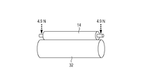
- FIG. 5 shows a method for measuring the electrical resistance of a charging member.
- Both ends of the conductive substrate 1 are brought into contact with a cylindrical metal 15 having the same curvature as that of the photoconductor so as to be parallel to each other by a loaded bearing.
- the cylindrical metal 15 is rotated by a motor (not shown), and a DC voltage of ⁇ 200 V is applied from the stabilized power supply while the charging member 14 in contact with the motor is rotated.
- the current flowing at this time is measured by the ammeter 16, and the resistance of the charging member is calculated.
- the load was 4.9 N each
- the diameter of the metal cylinder was 30 mm
- the rotation of the metal cylinder was a peripheral speed of 45 mm / sec.
- the charging member according to the present invention preferably has a crown shape that is thickest at the center in the longitudinal direction and narrows toward both ends in the longitudinal direction from the viewpoint of making the longitudinal nip width uniform with respect to the photoreceptor.
- the crown amount is preferably such that the difference between the outer diameter at the center and the outer diameter at a position 90 mm away from the center is not less than 30 ⁇ m and not more than 200 ⁇ m.
- the 10-point average surface roughness (Rzjis) of the surface of the charging member is preferably 8 ⁇ m or more and 100 ⁇ m or less. More preferably, they are 12 micrometers or more and 60 micrometers or less.
- interval (RSm) of a surface is 20 micrometers or more and 300 micrometers or less, More preferably, they are 50 micrometers or more and 200 micrometers or less.
- Rzjis and RSm are measured according to JIS B 0601-1994 surface roughness standards, and are measured using a surface roughness measuring instrument (trade name: SE-3500, manufactured by Kosaka Laboratory Ltd.).
- SE-3500 surface roughness measuring instrument
- the ten-point average surface roughness is an average value obtained by arbitrarily measuring six charging members. In the measurement, the cut-off value is set to 0.8 mm, and the evaluation length is set to 8 mm.
- the inventors of the present invention achieve both the maintenance of high-quality developability and the suppression of the occurrence of the above-described aggregated toner for suppressing toner slipping from the cleaning member that causes toner fixation and contamination on the surface of the charging member.
- the following four points are considered to be necessary for the toner.
- Inorganic fine particles (hereinafter also referred to as “external additives”) on the toner surface are difficult to be embedded in the toner. If the external additive is embedded in the toner, the following releasability of the toner applied by the external additive and the spacer effect described above cannot be expressed.
- Toner releasability The inventors of the present invention achieve both the maintenance of high-quality developability and the suppression of the occurrence of the above-described aggregated toner for suppressing toner slipping from the cleaning member that causes toner fixation and contamination on the surface of the charging member.
- the following four points are considered to be necessary for the toner.
- the present inventors define the surface properties of the silica fine particles, which are external additives, and at the same time, determine the external addition state of the silica fine particles present on the surface of the toner. It came to regulate.
- the “surface properties of silica fine particles” are defined as follows.
- the toner according to the present invention contains toner particles containing a binder resin and a colorant, and inorganic fine particles.
- the binder resin contained in the toner particles is also referred to as a binder resin T.
- the inorganic fine particles are silica fine particles
- the toner contains 0.40 parts by mass or more and 1.50 parts by mass or less of the silica fine particles per 100 parts by mass of the toner particles.
- the silica fine particles are contained in an amount of 0.50 to 1.30 parts by mass per 100 parts by mass of the toner particles.
- the releasability of the toner can be improved, and at the same time, the embedding of the toner in the external additive can be suppressed. As a result, it is possible to suppress toner slipping from the cleaning member and adhesion of dirt to the charging member.
- the content of the silica fine particles is less than 0.40 parts by mass, the releasability of the toner is not sufficient, and toner that passes through the cleaning member is generated.
- the silica fine particles are treated with 15.0 parts by mass or more and 40.0 parts by mass or less of silicone oil based on 100 parts by mass of the silica base material, and the silicone oil is fixed on the basis of carbon amount.
- the rate (%) is 70% or more.
- the carbon-based immobilization rate of silicone oil corresponds to the amount of silicone oil molecules chemically bonded to the surface of the silica base.
- the cohesiveness and friction coefficient between the silica fine particles can be controlled to the ranges necessary for the present invention by controlling the number of treatment parts and the immobilization ratio with the silicone oil within the above ranges. Further, the same properties can be imparted to the toner to which the silica fine particles are externally added, and the effect (2) can be easily improved.
- the present inventors presume the effect expression mechanism as follows.
- the present invention is characterized by silica fine particles having a relatively large number of silicone oil-treated parts and a high immobilization rate. Such silica fine particles can increase the coefficient of friction without deteriorating the cohesiveness between the silica fine particles.
- the present inventors consider that the deterioration of cohesiveness can be reduced by fixing the terminal of the silicone oil molecule to the surface of the silica base material. Accordingly, the generation of the agglomerated toner described above can be suppressed, and the toner slipping from the cleaning member and the adhesion of dirt to the charging member can be suppressed.
- the toner according to the present invention is a toner in which the coefficient of friction between the toners is increased without deteriorating the cohesiveness between the toners. This makes it possible to obtain the effects (2) and (3) at the same time.
- the number of parts of the silica fine particles treated with silicone oil is more preferably 17.0 parts by mass or more and 30.0 parts by mass or less with respect to 100 parts by mass of the silica raw material.
- the conversion rate (%) is more preferably 90% or more. Thereby, expression of the effect mentioned above can be raised more.
- the toner according to the present invention defines the “external addition state of silica fine particles” as follows.
- the coverage X1 can be calculated from the ratio of the Si element detection intensity when the toner is measured to the Si element detection intensity when the silica fine particle is measured by ESCA.
- the coverage X1 indicates the proportion of the area of the toner particle surface that is actually covered with silica fine particles.
- the coverage X1 is 50.0 area% or more and 75.0 area% or less, the fluidity and chargeability of the toner can be controlled to be in a good state through the durability test.
- the coverage X1 is less than 50.0 area%, it is not possible to obtain sufficient ease of toner loosening described later. For this reason, under severe evaluation conditions as described above, the fluidity is deteriorated due to the deterioration of the toner, the releasability from the developing member is insufficient, and the problem of leaving the durability cannot be improved.
- the theoretical coverage X2 by the silica fine particles is calculated from the following formula 4 using the number of parts by mass of the silica fine particles per 100 parts by mass of the toner particles, the particle size of the silica fine particles, and the like. This indicates the ratio of the area that can theoretically cover the toner particle surface.
- Diffusion index indicates the difference between the actual coverage X1 and the theoretical coverage X2.
- the degree of this divergence is considered to indicate the number of silica fine particles laminated in two and three layers in the vertical direction from the toner particle surface.
- the diffusion index is 1, but this is a case where the coverage ratio X1 coincides with the theoretical coverage ratio X2, and there is no state where there are no two or more layers of silica fine particles.
- silica fine particles are present on the toner surface as aggregated secondary particles, a difference between the actually measured coverage and the theoretical coverage is generated, and the diffusion index is lowered.
- the diffusion index can be paraphrased as indicating the amount of silica fine particles present as secondary particles.
- the diffusion index is in the range represented by the above formula 2, and it is considered that this range is larger than that of the toner manufactured by the conventional technique.
- a large diffusion index indicates that the amount of silica fine particles on the surface of the toner particles present as secondary particles is small and the amount present as primary particles is large.
- the upper limit of the diffusion index is 1.
- the present inventors have found that when the coverage ratio X1 and the diffusion index satisfy the range represented by Formula 2 at the same time, the ease of toner loosening during pressurization can be greatly improved.
- the present inventors presume the reason why the ease of toner loosening is improved when the coverage X1 and the diffusion index satisfy the range represented by Formula 2 at the same time. It is considered that when toner is present in a narrow and high pressure place such as a blade nip, the toner tends to be in a state of “meshing” so that external additives existing on the surface do not collide with each other. . At this time, if there are many silica fine particles present as secondary particles, the influence of meshing becomes too great, and it becomes difficult to loosen the toners quickly.
- silica fine particles existing as primary particles are buried in the surface of the toner particles, and the fluidity of the toner is lowered. At that time, it is presumed that the influence of meshing between silica fine particles existing as secondary particles that are not buried becomes large, and hinders the ease of loosening of the toner.
- the toner according to the present invention since many silica fine particles are present as primary particles, even when the toner is deteriorated, it is difficult for the toner to bite between the toners, and even when the toner is rubbed in the transfer process or the like. , Very easy to break into each grain. That is, it has become possible to dramatically improve the “easy to loosen toner” described in the above (4), which was difficult only by the conventional control of the coverage X1.
- the present inventors have found that when the coverage ratio X1 and the diffusion index satisfy the range represented by Formula 2 at the same time, the degree of progress of toner deterioration is greatly reduced.
- the reason for this is that when the silica fine particles on the surface of the toner particles are present as primary particles, even if the toners are in contact with each other, the possibility that the silica fine particles are in contact with each other is reduced, and the pressure applied to the silica fine particles is reduced. It is guessed that. That is, the effect (1) described above can be obtained.
- the boundary line of the diffusion index in the present invention is a function with the coverage X1 as a variable in the range where the coverage X1 is 50.0 area% or more and 75.0 area% or less.
- the calculation of this function was obtained empirically from the phenomenon that the toner is sufficiently easily loosened when pressurized when obtaining the coverage X1 and the diffusion index by changing the silica fine particles, external addition conditions and the like. .
- FIG. 6 is a graph plotting the relationship between the coverage ratio X1 and the diffusion index by producing a toner in which the coverage ratio X1 is arbitrarily changed by changing the amount of silica fine particles to be added using three types of external additive mixing conditions. It is. Of the toners plotted in this graph, it was found that the toner plotted in the region satisfying the expression 2 sufficiently improves the ease of loosening during pressurization.
- the boundary line of the diffusion index is considered to be a function with the coverage X1 as a variable. That is, there was a correlation between the coverage X1 and the diffusion index, and it was experimentally determined that it is important to control the diffusion index according to the coverage X1.
- the above (1) to (4) are necessary as the toner conditions for suppressing the occurrence of toner slipping from the cleaning member and for preventing the charging member from being contaminated.
- the toner exhibits the above characteristics (1) to (4) due to a synergistic effect by controlling both the “surface properties of the silica fine particles” and the “external addition state of the silica fine particles”, and the charging member according to the present invention. It is presumed that the above problems can be solved by using together.
- the toner according to the present invention contains a colorant.
- the colorant preferably used in the present invention include the following.
- organic pigments or organic dyes as cyan colorants include copper phthalocyanine compounds and derivatives thereof, anthraquinone compounds, and basic dye lake compounds.
- organic pigments or organic dyes as magenta colorants include the following. Condensed azo compounds, diketopyrrolopyrrole compounds, anthraquinones, quinacridone compounds, basic dye lake compounds, naphthol compounds, benzimidazolone compounds, thioindigo compounds, perylene compounds.
- organic pigments or organic dyes as yellow colorants include compounds represented by condensed azo compounds, isoindolinone compounds, anthraquinone compounds, azo metal complexes, methine compounds, and allylamide compounds.
- black colorant examples include carbon black, the above-described yellow colorant, magenta colorant, and cyan colorant that are toned to black.
- a colorant When using a colorant, it is preferably used by adding 1 part by mass or more and 20 parts by mass or less with respect to 100 parts by mass of the polymerizable monomer or the binder resin T.
- the toner according to the present invention can contain a magnetic material.
- the magnetic material can also serve as a colorant.
- the magnetic material used in the present invention is mainly composed of triiron tetroxide or ⁇ -iron oxide, and may contain elements such as phosphorus, cobalt, nickel, copper, magnesium, manganese, and aluminum.
- the shape of the magnetic material includes a polyhedron, octahedron, hexahedron, sphere, needle shape, flake shape, etc., but a polyhedron, octahedron, hexahedron, sphere and the like having a small anisotropy can reduce the image density. It is preferable in terms of enhancement.
- the content of the magnetic substance in the present invention is preferably 50 parts by mass or more and 150 parts by mass or less with respect to 100 parts by mass of the polymerizable monomer or the binder resin T.
- the toner according to the present invention preferably contains a wax.
- the wax preferably includes a hydrocarbon wax.
- Other waxes include the following. Amide waxes, higher fatty acids, long chain alcohols, ketone waxes, ester waxes, and derivatives such as these graft compounds and block compounds. If necessary, two or more kinds of waxes may be used in combination. Among these, when the hydrocarbon wax by the Fischer-Tropsch method is used, the high temperature offset resistance can be kept good while maintaining the developability well for a long time.
- These hydrocarbon waxes may contain an antioxidant within a range that does not affect the chargeability of the toner.
- the content of the wax is preferably 4.0 parts by mass or more and 30.0 parts by mass or less, more preferably 16.0 parts by mass or more and 28.0 parts by mass or less with respect to 100 parts by mass of the binder resin T. is there.
- a charge control agent can be contained in the toner particles as necessary. By blending the charge control agent, the charge characteristics can be stabilized and the optimum triboelectric charge amount can be controlled according to the development system.
- the charge control agent As the charge control agent, a known one can be used, and a charge control agent that has a high charging speed and can stably maintain a constant charge amount is particularly preferable. Further, when the toner particles are produced by a direct polymerization method, a charge control agent having a low polymerization inhibition property and substantially free from a solubilized product in an aqueous medium is particularly preferable.
- the toner according to the present invention may contain these charge control agents alone or in combination of two or more.
- the blending amount of the charge control agent is preferably 0.3 parts by mass or more and 10.0 parts by mass or less, more preferably 0.5 parts by mass with respect to 100 parts by mass of the polymerizable monomer or binder resin T.
- the amount is 8.0 parts by mass or more.
- the toner according to the present invention contains toner particles and inorganic fine particles.
- the inorganic fine particles are silica fine particles.
- the silica fine particles used in the present invention are produced by hydrophobizing with 15.0 parts by mass or more and 40.0 parts by mass or less of silicone oil with respect to 100 parts by mass of the silica raw material.
- the degree of the hydrophobization treatment is preferably 70% or more, more preferably 80% or more, as measured by a methanol titration test from the viewpoint of suppressing the decrease in chargeability in a high-temperature and high-humidity environment.
- silicone oil examples include dimethyl silicone oil, methylphenyl silicone oil, ⁇ -methylstyrene modified silicone oil, chlorophenyl silicone oil, and fluorine modified silicone oil.
- the kinematic viscosity at 25 ° C. of the silicone oil used for the treatment of the silica fine particles is preferably 30 cSt or more and 500 cSt or less.
- the kinematic viscosity of the silicone oil is closely related to the molecular chain length of the silicone oil, and when the kinematic viscosity is in the above range, it is preferable because the aggregation degree of the silica fine particles can be easily controlled to a suitable range.
- silicone oil is 40 cSt or more and 300 cSt or less.
- the apparatus for measuring the kinematic viscosity of silicone oil include a capillary type kinematic viscometer (manufactured by Kashiwagi Scientific Instruments Co., Ltd.) or a fully automatic microkinematic viscometer (manufactured by Viscotech Co., Ltd.).
- the silica fine particles used in the present invention are preferably those obtained by treating the silica raw material with silicone oil and then treating with at least one of alkoxysilane and silazane.
- the surface of the silica base material that could not be hydrophobized with silicone oil can be hydrophobized, so that highly hydrophobized silica fine particles can be obtained stably.
- the present inventors consider as follows. Of the silicone oil molecule ends on the surface of the silica fine particles, only one end has a degree of freedom, which affects the cohesiveness between the silica fine particles.
- the silicone oil molecular terminal is hardly present on the outermost surface of the silica fine particles, so that the cohesiveness of the silica fine particles can be further reduced.
- the cohesiveness between the toners when externally added can be greatly reduced, and the ease of toner loosening can be improved.
- the silica base material is, for example, so-called wet silica produced by vapor phase oxidation of silicon halide, so-called dry process or dry silica called fumed silica, and water glass. Both can be used.
- the silica fine particles used in the present invention may be crushed during the above treatment step or after the treatment step. Furthermore, when performing a two-stage process, it is also possible to perform a crushing process between processes.
- the surface treatment with silicone oil and the surface treatment with alkoxysilane and silazane may be either dry treatment or wet treatment.
- the specific procedure of the surface treatment with the silicone oil of the silica raw material is, for example, by reacting the silica fine particles in a solvent (preferably adjusted to pH 4 with an organic acid or the like) in which the silicone oil is dissolved. Remove. Thereafter, crushing treatment may be performed.
- a solvent preferably adjusted to pH 4 with an organic acid or the like
- Crushed silicone oil-treated silica fine particles are put into a solvent in which at least one of alkoxysilane and silazane is dissolved and reacted. Thereafter, the solvent is removed and pulverization is performed. Further, the following method may be used. For example, in the surface treatment with silicone oil, silica fine particles are put into a reaction vessel. Then, alcohol water is added with stirring in a nitrogen atmosphere, silicone oil is introduced into the reaction tank to perform surface treatment, and the mixture is further heated and stirred to remove the solvent, followed by crushing treatment.
- the surface treatment is performed by introducing at least one of alkoxysilane and silazane while stirring in a nitrogen atmosphere, and further, the mixture is heated and stirred to remove the solvent and then cooled.
- alkoxysilane examples include methyltrimethoxysilane, dimethyldimethoxysilane, phenyltrimethoxysilane, methyltriethoxysilane, dimethyldiethoxysilane, and phenyltriethoxysilane.
- hexamethyldisilazane can be preferably exemplified as silazane.
- the amount of treatment with at least one of these alkoxysilanes and silazanes is 0.1 parts by mass or more and 20.0 parts by mass or less as a total amount of at least one of alkoxysilane and silazane with respect to 100 parts by mass of the silica raw material.
- a method of performing a heat treatment for the reaction of silicone oil in the process of obtaining silica fine particles can be suitably exemplified.
- the heat treatment temperature is preferably 100 ° C. or higher. The higher the heat treatment temperature, the higher the immobilization rate.
- This heat treatment step is preferably performed immediately after the silicone oil treatment, but when the crushing treatment is performed, the heat treatment step may be performed after the crushing treatment step.
- the silica fine particles used in the present invention preferably have an apparent density of 15 g / L or more and 50 g / L or less.
- the apparent density of the silica fine particles being in the above range indicates that the silica fine particles are difficult to be densely packed and exist with a lot of air between the fine particles, and the apparent density is very low. For this reason, even in the toner, since the toner is less likely to be clogged closely, the deterioration rate can be significantly reduced.
- a more preferable range is 18 g / L or more and 45 g / L or less.
- Examples of means for controlling the apparent density of the silica fine particles within the above range include adjusting the particle size of the silica raw material used for the silica fine particles, the presence / absence and the strength of the above-mentioned crushing treatment, and the treatment amount of the silicone oil. .
- the particle size of the silica raw material By reducing the particle size of the silica raw material, the BET specific surface area of the silica fine particles to be obtained becomes large and a large amount of air can be interposed, so that the apparent density can be reduced.
- By performing the crushing treatment relatively large secondary particles contained in the silica fine particles can be loosened into relatively small secondary particles, and the apparent density can be reduced.
- the silica base material used in the present invention has a specific surface area (BET specific surface area) measured by a BET method by nitrogen adsorption of 130 m 2 / g or more and 330 m 2 / g or less in order to impart good fluidity to the toner. Is preferred. In the case of this range, the fluidity and chargeability imparted to the toner are easily secured through durability.
- the BET specific surface area of the silica base material is more preferably 200 m 2 / g or more and 320 m 2 / g or less.
- the measurement of the specific surface area (BET specific surface area) measured by the BET method by nitrogen adsorption is performed according to JISZ8830 (2001).
- the measuring apparatus an “automatic specific surface area / pore distribution measuring apparatus, TriStar 3000 (manufactured by Shimadzu Corporation)” which employs a gas adsorption method based on a constant volume method as a measuring method is used.
- the number average particle diameter of the primary particles of the silica base material used in the present invention is preferably 3 nm or more and 50 nm or less, and more preferably 5 nm or more and 40 nm or less.
- the toner according to the present invention preferably has a weight average particle diameter (D4) of 5.0 ⁇ m or more and 10.0 ⁇ m or less, more preferably 5.5 ⁇ m or more, 9 from the viewpoint of a balance between developability and fixability. .5 ⁇ m or less.
- D4 weight average particle diameter
- the average circularity of the toner particles is preferably 0.960 or more, and more preferably 0.970 or more.
- the shape of the toner is a sphere or a shape close to this, and it is easy to obtain a uniform triboelectric chargeability with excellent fluidity. Therefore, it is preferable because high developability can be easily maintained even in the latter half of the durability.
- toner particles having a high average circularity are preferable because the coverage X1 and the diffusion index can be easily controlled within the scope of the present invention in the external addition treatment of inorganic fine particles described later. Further, from the viewpoint of ease of loosening of the toner at the time of pressurization, it is preferable because the meshing effect on the surface shape of the toner particles hardly occurs and the ease of loosening can be further improved.
- the toner according to the present invention can adjust the number of silica fine particles treated with silicone oil, the carbon oil-based immobilization rate of silicone oil, the coverage X1, and the diffusion index. Moreover, if it is a manufacturing method which has the process of adjusting an average circularity preferably, in another manufacturing process, it will not specifically limit, It can manufacture by a well-known method.
- the binder resin T, the colorant, and other additives such as a release agent as necessary are sufficiently mixed by a mixer such as a Henschel mixer or a ball mill.
- a mixer such as a Henschel mixer or a ball mill.
- the toner material is dispersed or dissolved by using a heat kneader such as a heating roll, a kneader, and an extruder to disperse or dissolve the toner material.
- pulverization, classification, and if necessary, surface treatment is performed to obtain toner particles. obtain. Either the classification or the surface treatment may be performed first. In the classification step, it is preferable to use a multi-division classifier in terms of production efficiency.
- the pulverization can be performed by a method using a known pulverizer such as a mechanical impact type or a jet type.
- a known pulverizer such as a mechanical impact type or a jet type.
- a hot water bath method in which finely pulverized (classified as necessary) toner particles are dispersed in hot water, or a method of passing through a hot air stream may be used.
- Examples of means for applying a mechanical impact force include a method using a mechanical impact pulverizer such as a kryptron system manufactured by Kawasaki Heavy Industries, Ltd. or a turbo mill manufactured by Turbo Industry. Further, there is a method of applying a mechanical impact force to the toner by a compressive force or a frictional force, such as a mechano-fusion system manufactured by Hosokawa Micron Corporation or a hybridization system device manufactured by Nara Machinery Co., Ltd.
- the toner particles used in the present invention are preferably those produced in an aqueous medium such as a dispersion polymerization method, an association aggregation method, a solution suspension method, and a suspension polymerization method. More preferably.
- the suspension polymerization method is a method in which a polymerizable monomer and a colorant, and other additives such as a polymerization initiator, a crosslinking agent, and a charge control agent are uniformly dissolved or dispersed as necessary.
- a meter composition is obtained.
- the polymerizable monomer composition is dispersed in a continuous layer (for example, an aqueous phase) containing a dispersion stabilizer using a suitable stirrer, and then the polymerizable monomer in the polymerizable monomer composition is used.
- the toner is polymerized to obtain toner particles having a desired particle size.
- the toner particles obtained by this suspension polymerization method (hereinafter also referred to as “polymerized toner particles”) have a substantially spherical shape, and therefore satisfy a predetermined average circularity and have a charge amount of This is preferable because the distribution is relatively uniform.
- polymerizable monomer constituting the polymerizable monomer composition.
- styrene or a styrene derivative is preferably used alone or mixed with another polymerizable monomer from the viewpoint of the development characteristics and durability of the toner.
- the polymerization initiator used in the suspension polymerization method preferably has a half-life of 0.5 hours or more and 30.0 hours or less during the polymerization reaction. Moreover, it is preferable that the addition amount of a polymerization initiator is 0.5 to 20.0 mass parts with respect to 100 mass parts of polymerizable monomers.
- polymerization initiator examples include azo or diazo polymerization initiators and peroxide polymerization initiators.
- a crosslinking agent may be added during the polymerization reaction, and a preferable addition amount is 0.1 parts by mass or more and 10.0 parts by mass or less with respect to 100 parts by mass of the polymerizable monomer.
- a cross-linking agent a compound having two or more polymerizable double bonds is mainly used. Examples thereof include aromatic divinyl compounds, carboxylic acid esters having two double bonds, divinyl compounds, and compounds having three or more vinyl groups. These are used alone or as a mixture of two or more.
- the production of toner particles by the suspension polymerization method will be specifically described, but the present invention is not limited to this.
- a disperser such as a homogenizer, a ball mill, or an ultrasonic disperser is dispersed and stabilized.
- a disperser such as a homogenizer, a ball mill, or an ultrasonic disperser
- the particle size of the obtained toner particles becomes sharper by using a disperser such as a high-speed stirrer or an ultrasonic disperser to obtain a desired toner particle size all at once.
- the polymerization initiator may be added at the same time as other additives are added to the polymerizable monomer, or may be mixed immediately before being suspended in the aqueous medium. Also, a polymerization initiator dissolved in a polymerizable monomer or solvent can be added immediately after granulation and before starting the polymerization reaction.
- stirring may be performed using a normal stirrer to such an extent that the particle state is maintained and the floating and settling of particles is prevented.
- dispersion stabilizer known surfactants, organic dispersants or inorganic dispersants can be used.
- inorganic dispersants are less likely to produce harmful ultrafine powders, and because of their steric hindrance, dispersion stability is obtained, so even if the reaction temperature is changed, stability is not easily lost, and cleaning is easy and does not adversely affect toner. Therefore, it can be preferably used.
- inorganic dispersants include trivalent calcium phosphates such as tricalcium phosphate, magnesium phosphate, aluminum phosphate, zinc phosphate and hydroxyapatite; carbonates such as calcium carbonate and magnesium carbonate; calcium metasuccinate, calcium sulfate, Inorganic salts such as barium sulfate; inorganic compounds such as calcium hydroxide, magnesium hydroxide and aluminum hydroxide.
- inorganic dispersants are preferably used in an amount of 0.20 parts by mass or more and 20.00 parts by mass or less with respect to 100 parts by mass of the polymerizable monomer.
- the said dispersion stabilizer may be used independently and may use multiple types together. Furthermore, you may use together 0.0001 mass part or more and 0.1000 mass part or less surfactant with respect to 100 mass parts of polymerizable monomers.
- the polymerization temperature is set to 40 ° C or higher, generally 50 ° C to 90 ° C.
- the toner according to the present invention is obtained by externally adding silica fine particles, which are inorganic fine particles, to the toner particles and adhering them to the surface of the toner particles. It is also possible to add a classification step to the production process (before mixing the inorganic fine particles) to remove coarse powder and fine powder contained in the toner particles.
- particles having a primary particle number average particle diameter (D1) of 80 nm or more and 3 ⁇ m or less may be added.
- lubricants such as fluororesin powder, zinc stearate powder and polyvinylidene fluoride powder; abrasives such as cerium oxide powder, silicon carbide powder and strontium titanate powder; spacer particles such as silica affect the effect of the present invention. A small amount can be used.
- a mixing processing apparatus for externally mixing the silica fine particles a known mixing processing apparatus can be used, but an apparatus as shown in FIG. 7 is preferable in that the coverage X1 and the diffusion index can be easily controlled.
- FIG. 7 is a schematic diagram showing an example of a mixing apparatus that can be used when externally mixing the silica fine particles used in the present invention.
- the mixing processing device is configured to take a share in a narrow clearance portion with respect to toner particles and silica fine particles, so that the silica fine particles adhere to the toner particle surface while loosening the silica fine particles from the secondary particles to the primary particles. can do.
- the coverage X1 and the diffusion index are preferred ranges in the present invention in that the toner particles and the silica fine particles are easily circulated in the axial direction of the rotating body, and are sufficiently uniformly mixed before the fixing proceeds. Easy to control.
- FIG. 8 is a schematic diagram showing an example of the configuration of the stirring member used in the mixing treatment apparatus.
- the mixing apparatus for externally mixing silica fine particles has a rotating body 18 having at least a plurality of stirring members 19 installed on the surface thereof, a drive unit 24 that rotationally drives the rotating body 18, and a gap between the stirring member 19. And a main body casing 17 provided.
- the clearance (clearance) between the inner peripheral portion of the main body casing 17 and the stirring member 19 gives a uniform share to the toner particles and easily adheres to the toner particle surface while loosening the silica fine particles from the secondary particles to the primary particles. In order to do this, it is important to keep it constant and minute.
- the diameter of the inner peripheral portion of the main body casing 17 is not more than twice the diameter of the outer peripheral portion of the rotating body 18.
- 7 shows an example in which the diameter of the inner peripheral portion of the main body casing 17 is 1.7 times the diameter of the outer peripheral portion of the rotating body 18 (the diameter of the body portion obtained by removing the stirring member 19 from the rotating body 18). If the diameter of the inner peripheral portion of the main body casing 17 is not more than twice the diameter of the outer peripheral portion of the rotating body 18, the processing space in which the force acts on the toner particles is appropriately limited. A sufficient impact force is applied to the silica fine particles.
- the clearance is important in terms of applying a sufficient share to the silica fine particles. Specifically, when the diameter of the inner peripheral part of the main body casing 17 is about 130 mm, the clearance is about 2 mm or more and about 5 mm or less, and when the inner peripheral part diameter of the main body casing 17 is about 800 mm, the clearance is about 10 mm or more and 30 mm or less. It should be about.
- the rotating body 18 is rotated by the drive unit 24 using the mixing processing device, and the toner particles and the silica fine particles charged into the mixing processing device are stirred and mixed. Silica fine particles are externally added to the surface of the toner particles.
- At least a part of the plurality of stirring members 19 is formed as a feeding stirring member 19 a that sends toner particles and silica fine particles in one axial direction of the rotating body as the rotating body 18 rotates. Is done. Further, at least a part of the plurality of stirring members 19 is formed as a return stirring member 19b that returns the toner particles and the silica fine particles to the other direction in the axial direction of the rotating body 18 as the rotating body 18 rotates. .
- feed direction the direction from the raw material inlet 21 toward the product outlet 22 (in FIG. 7).
- the plate surface of the feeding stirring member 19a is inclined so as to feed the toner particles in the feeding direction (31).
- the plate surface of the stirring member 19b is inclined so as to send toner particles and silica fine particles in the return direction (30).
- the stirring members 19a and 19b are a set of a plurality of members arranged at intervals in the circumferential direction of the rotating body 18.
- the stirring members 19a and 19b form a pair of two members on the rotating body 18 at intervals of 180 degrees, but three members at intervals of 120 degrees or intervals of 90 degrees. It is good also as a set of many members, such as four sheets.
- a total of 12 stirring members 19a and 19b are formed at equal intervals.
- D indicates the width of the stirring member, and d indicates an interval indicating the overlapping portion of the stirring member. From the viewpoint of efficiently feeding the toner particles and silica fine particles in the feeding direction and the returning direction, it is preferable that D has a width of about 20% to 30% with respect to the length of the rotating body 24 in FIG. FIG. 8 shows an example of 23%.
- the stirring members 19a and 19b preferably have an overlap portion d between the stirring member 19b and the stirring member to some extent when an extension line is drawn vertically from the end position of the stirring member 19a. As a result, it is possible to efficiently share the silica fine particles that are secondary particles. D is preferably 10% or more and 30% or less in terms of applying a share.
- the shape of the blade in addition to the shape shown in FIG. 8, if the toner particles can be sent in the feeding direction and the returning direction and the clearance can be maintained, the shape having a curved surface and the tip blade portion are A paddle structure coupled to the rotating body 2 with a rod-like arm may be used.
- the apparatus shown in FIG. 7 includes a rotating body 18 having a plurality of stirring members 19 installed on the surface, a drive unit 24 that rotationally drives the rotating body 18, and a main body casing 17 that is provided with a gap between the stirring member 19.
- the apparatus shown in FIG. 7 has a jacket 20 that is provided on the inner side of the main body casing 17 and on the end face 26 of the rotating body and through which a cooling medium can flow.
- the apparatus shown in FIG. 7 has a raw material inlet 21 formed in the upper part of the main body casing 17 in order to introduce toner particles and silica fine particles. Further, the apparatus shown in FIG. 7 has a product discharge port 22 formed in the lower portion of the main body casing 17 in order to discharge the toner subjected to the external addition mixing process from the main body casing 17. Further, in the apparatus shown in FIG. 7, a raw material inlet inner piece 27 is inserted into the raw material inlet 21, and a product outlet inner piece 28 is inserted into the product outlet 22.
- the raw material inlet inner piece 27 is taken out from the raw material inlet 21, and the toner particles are put into the processing space 25 from the raw material inlet 21.
- silica fine particles are introduced into the treatment space 25 from the raw material inlet 21 and the raw material inlet inner piece 27 is inserted.
- the rotating body 18 is rotated by the drive unit 24 (29 indicates the direction of rotation), and the processed material introduced above is externally added while being stirred and mixed by a plurality of stirring members 19 provided on the surface of the rotating body 18. Mix.
- the order of loading may be such that silica fine particles are first charged from the raw material inlet 21 and then toner particles are charged from the raw material inlet 21. Further, after the toner particles and the silica fine particles are mixed in advance by a mixer such as a Henschel mixer, the mixture may be charged from the raw material inlet 21 of the apparatus shown in FIG.
- the power of the driving unit 24 is controlled to be 0.2 W / g or more and 2.0 W / g or less, so that the coverage X1 and the diffusion index defined in the present invention are determined. Is preferable in obtaining. Moreover, it is more preferable to control the power of the drive unit 24 to 0.6 W / g or more and 1.6 W / g or less.
- the treatment time is not particularly limited, but is preferably 3 minutes or more and 10 minutes or less. When the treatment time is shorter than 3 minutes, the coverage X1 and the diffusion index tend to be low.
- the number of rotations of the stirring member during external addition mixing is not particularly limited.
- the rotation speed of the stirring member 19 when the shape of the stirring member 19 is that of FIG. 8 is 800 rpm or more and 3000 rpm or less. It is preferable. By being 800 rpm or more and 3000 rpm or less, it becomes easy to obtain the coverage X1 and the diffusion index defined in the present invention.
- a particularly preferable treatment method is to have a pre-mixing step before the external addition mixing operation.
- the silica fine particles are highly uniformly dispersed on the surface of the toner particles, so that the coverage X1 is likely to be increased and the diffusion index is likely to be further increased.
- the power of the drive unit 24 is set to 0.06 W / g or more and 0.20 W / g or less, and the processing time is set to 0.5 minutes or more and 1.5 minutes or less. It is preferable. If the load power is lower than 0.06 W / g or the processing time is shorter than 0.5 minutes as the premixing processing condition, sufficient uniform mixing is difficult to perform as premixing. On the other hand, if the load power is higher than 0.20 W / g or the processing time is longer than 1.5 minutes as the pre-mixing processing condition, the silica fine particles are fixed on the surface of the toner particles before sufficient uniform mixing is performed. It may be done.
- the number is preferably 50 rpm or more and 500 rpm or less. By being 50 rpm or more and 500 rpm or less, it becomes easy to obtain the coverage X1 and the diffusion index defined in the present invention.
- the product discharge port inner piece 28 is taken out from the product discharge port 22, and the rotating body 18 is rotated by the drive unit 24, and the toner is discharged from the product discharge port 22.
- coarse particles and the like are separated by a sieve such as a circular vibration sieve as necessary to obtain a toner.
- ⁇ Quantification method of silica fine particles (1) Determination of the content of silica fine particles in the toner (standard addition method) 3 g of toner is put in an aluminum ring having a diameter of 30 mm, and pellets are produced at a pressure of 10 tons. Then, the intensity of silicon (Si) is obtained by wavelength dispersive X-ray fluorescence analysis (XRF) (Si intensity-1). The measurement conditions may be those optimized by the XRF apparatus to be used, but all the series of intensity measurements are performed under the same conditions. To the toner, silica fine particles having a primary particle number average particle diameter of 12 nm are added in an amount of 1.0 mass% with respect to the toner, and then mixed by a coffee mill.
- Si strength-2 the strength of Si is determined in the same manner as described above.
- Si strength-3 the strength of Si is also obtained for a sample in which silica fine particles are added and mixed at 2.0 mass% and 3.0 mass% with respect to the toner.
- silica fine particles are quantified through the following steps. 5 g of toner is weighed into a 200 ml polycup with a lid using a precision balance, 100 ml of methanol is added, and the mixture is dispersed for 5 minutes with an ultrasonic disperser. Attract the toner with a neodymium magnet and discard the supernatant. This operation of dispersing with methanol and discarding the supernatant was repeated three times.
- the magnetic substance content W (% by mass) in the magnetic toner can be obtained.
- the mass of the particle C is multiplied by 0.9666 (Fe 2 O 3 ⁇ Fe 3 O 4 ).
- the amount of silica particles added externally is calculated.
- Externally added silica fine particle amount (mass%) silica content in toner (mass%) ⁇ silica content in particle A (mass%)
- ⁇ Measurement method of coverage X1> The coverage X1 with the silica fine particles on the toner surface is calculated as follows. The following apparatus is used under the following conditions, and elemental analysis of the toner surface is performed. -Measuring device: Quantum 2000 (trade name, manufactured by ULVAC-PHI Co., Ltd.) ⁇ X-ray source: Monochrome Al K ⁇ -Xray Setting: 100 ⁇ m ⁇ (25 W (15 KV)) ⁇ Photoelectron extraction angle: 45 degrees ⁇ Neutralization condition: Combined use of neutralization gun and ion gun ⁇ Analysis area: 300 ⁇ 200 ⁇ m ⁇ Pass Energy: 58.70eV ⁇ Step size: 1.25eV ⁇ Analysis software: Maltipak (PHI)
- the peaks of C 1c B.E. 280 to 295 eV
- O 1s B.E. 525 to 540 eV
- Si 2p B.E. 95 to 113 eV
- the elemental analysis of the silica fine particles is performed, and the quantitative value of the Si element obtained here is Y2.
- the coverage X1 with the silica fine particles on the surface of the toner is defined as follows using Y1 and Y2.
- Coverage ratio X1 (area%) Y1 / Y2 ⁇ 100
- the silica fine particles separated from the toner surface are used as a measurement sample, the silica fine particles are separated from the toner particles by the following procedure.
- the toner particles are restrained using a neodymium magnet, and the supernatant is collected.
- Silica fine particles are collected by drying the supernatant. If a sufficient amount of silica fine particles cannot be collected, this operation is repeated.
- the silica fine particles may be selected from the collected external additive using a centrifugal separation method or the like.
- non-magnetic toner 160 g of sucrose (manufactured by Kishida Chemical) is added to 100 ml of ion-exchanged water, and dissolved with a hot water bath to prepare a sucrose concentrate. A sucrose concentrate 31 g and 6 mL of Contaminone N are put into a centrifuge tube to prepare a dispersion. 1 g of toner is added to this dispersion and the mass of toner is loosened with a spatula or the like.
- sucrose manufactured by Kishida Chemical
- silica fine particles are selected from the collected external additives using a centrifugal separation method or the like.
- the weight average particle diameter (D4) of the toner is calculated as follows (also calculated in the case of toner particles).
- a precise particle size distribution measuring device “Coulter Counter Multisizer 3” (registered trademark, manufactured by Beckman Coulter, Inc.) using a pore electrical resistance method equipped with an aperture tube of 100 ⁇ m is used.
- the attached dedicated software “Beckman Coulter Multisizer 3 Version 3.51” (manufactured by Beckman Coulter, Inc.) is used. The measurement is performed with 25,000 effective measurement channels.
- electrolytic aqueous solution used for the measurement special grade sodium chloride is dissolved in ion-exchanged water so that the concentration becomes 1% by mass, for example, “ISOTON II” (manufactured by Beckman Coulter, Inc.) can be used.
- the bin interval to logarithmic particle size
- the particle size bin to 256 particle size bin
- the particle size range from 2 ⁇ m to 60 ⁇ m.
- the specific measurement method is as follows. (1) In a glass 250 ml round bottom beaker for exclusive use of Multisizer 3, 200 ml of the electrolytic aqueous solution is placed and set on a sample stand, and the stirrer rod is stirred counterclockwise at 24 rpm. Then, dirt and bubbles in the aperture tube are removed by the “aperture flush” function of the dedicated software. (2) Put 30 ml of the aqueous electrolytic solution into a glass 100 ml flat bottom beaker. In this, “Contaminone N” (nonionic surfactant, anionic surfactant, 10% by weight aqueous solution of neutral detergent for pH7 precision measuring instrument cleaning, made by organic builder, manufactured by Wako Pure Chemical Industries, Ltd.
- the height position of a beaker is adjusted so that the resonance state of the liquid level of the electrolyte solution in a beaker may become the maximum.
- 10 mg of toner is added to the electrolytic aqueous solution little by little and dispersed. Then, the ultrasonic dispersion process is continued for another 60 seconds.
- the temperature of the water tank is appropriately adjusted so as to be 10 ° C. or higher and 40 ° C. or lower.
- the electrolytic aqueous solution (5) in which the toner is dispersed is dropped using a pipette, and the measurement concentration is adjusted to 5%. Measurement is performed until the number of measured particles reaches 50,000.
- the measurement data is analyzed with the dedicated software attached to the apparatus, and the weight average particle diameter (D4) is calculated.
- the “average diameter” on the “analysis / volume statistics (arithmetic average)” screen when the graph / volume% is set in the dedicated software is the weight average particle diameter (D4).
- the number average particle size of the primary particles of the silica fine particles is calculated from the silica fine particle image on the toner surface taken with a Hitachi ultra-high resolution field emission scanning electron microscope S-4800 (Hitachi High-Technologies Corporation).
- the image capturing conditions of S-4800 are as follows.
- Sample preparation A conductive paste is thinly applied to a sample table (aluminum sample table 15 mm ⁇ 6 mm), and toner is sprayed on the surface. Further, air is blown to remove excess toner from the sample stage and sufficiently dry.
- the sample stage is set on the sample holder, and the height of the sample stage is adjusted to 36 mm by the sample height gauge.
- the particle diameter of at least 300 silica fine particles on the surface of the toner is measured to obtain an average particle diameter.
- the number average particle size of primary particles of silica fine particles (by calculating the maximum diameter of those that can be confirmed as primary particles and arithmetically averaging the obtained maximum diameter ( D1) Obtain (da).
- ⁇ Measuring method of average circularity of toner particles The average circularity of the toner particles is measured with a flow type particle image analyzer “FPIA-3000” (manufactured by Sysmex Corporation) under the measurement and analysis conditions during calibration.
- FPIA-3000 flow type particle image analyzer
- the specific measurement method is as follows. First, 20 ml of ion-exchanged water from which impure solids and the like are removed in advance is put in a glass container. In this, "Contaminone N" (nonionic surfactant, anionic surfactant, 10% by weight aqueous solution of neutral detergent for pH7 precision measuring instrument cleaning, made by organic builder, manufactured by Wako Pure Chemical Industries, Ltd. 0.2 ml of a diluted solution obtained by diluting 3) times with ion-exchanged water. Further, 0.02 g of a measurement sample is added, and a dispersion treatment is performed for 2 minutes using an ultrasonic disperser to obtain a dispersion for measurement.
- a dispersion liquid may become 10 to 40 degreeC.
- a desktop ultrasonic cleaner disperser for example, “VS-150” (manufactured by Velvo Crea) having an oscillation frequency of 50 kHz and an electric output of 150 W is used. Ion exchange water is added, and 2 ml of the above-mentioned Contaminone N is added to this water tank.
- the above-described flow type particle image analyzer equipped with “UPlanApro” (magnification 10 ⁇ , numerical aperture 0.40) as an objective lens is used, and the particle sheath “PSE-900A” (manufactured by Sysmex Corporation) is used as the sheath liquid. It was used.
- the dispersion prepared in accordance with the above procedure is introduced into the flow type particle image analyzer, and 3000 toner particles are measured in the HPF measurement mode and in the total count mode. Then, the binarization threshold at the time of particle analysis is set to 85%, the analysis particle diameter is limited to the circle equivalent diameter of 1.985 ⁇ m or more and less than 39.69 ⁇ m, and the average circularity of the toner particles is obtained.
- automatic focus adjustment is performed using standard latex particles (for example, “RESEARCH AND TEST PARTICLES Latex Microsphere Suspensions 5200A” manufactured by Duke Scientific, Inc. is diluted with ion-exchanged water). Thereafter, it is preferable to perform focus adjustment every two hours from the start of measurement.
- standard latex particles for example, “RESEARCH AND TEST PARTICLES Latex Microsphere Suspensions 5200A” manufactured by Duke Scientific, Inc. is diluted with ion-exchanged water.
- a flow type particle image measuring apparatus which has been issued a calibration certificate issued by Sysmex Corporation, which has been calibrated by Sysmex Corporation, is used. Measurement is performed under the measurement and analysis conditions when the calibration certificate is received, except that the analysis particle diameter is limited to a circle equivalent diameter of 1.985 ⁇ m or more and less than 39.69 ⁇ m.
- the measurement principle of the flow-type particle image measuring device “FPIA-3000” is to capture flowing particles as a still image and perform image analysis.
- the sample added to the sample chamber is fed into the flat sheath flow cell by a sample suction syringe.
- the sample fed into the flat sheath flow is sandwiched between sheath liquids to form a flat flow.
- the sample passing through the flat sheath flow cell is irradiated with strobe light at 1/60 second intervals, and the flowing particles can be photographed as a still image. Further, since the flow is flat, the image is taken in a focused state.
- the particle image is picked up by a CCD camera, and the picked-up image is image-processed at an image processing resolution of 512 ⁇ 512 pixels (0.37 ⁇ 0.37 ⁇ m per pixel), the contour of each particle image is extracted, and the particle image
- the projected area S, the peripheral length L, etc. are measured.
- the equivalent circle diameter and the circularity are obtained using the area S and the peripheral length L.
- the equivalent circle diameter is the diameter of a circle having the same area as the projected area of the particle image
- the circularity is 1.000, and as the degree of unevenness on the outer periphery of the particle image increases, the circularity becomes a smaller value.
- the range of the circularity of 0.200 to 1.000 is divided into 800, the arithmetic average value of the obtained circularity is calculated, and the value is defined as the average circularity.
- ⁇ Measurement method of true specific gravity of toner and silica fine particles The true specific gravity of the toner and the silica fine particles was measured by a dry automatic densimeter autopycnometer (manufactured by Yuasa Ionics). The conditions are as follows. Cell: SM cell (10 ml) Sample amount: 2.0 g (toner), 0.05 g (silica fine particles)
- This measurement method measures the true specific gravity of a solid / liquid based on a gas phase substitution method. Similar to the liquid phase replacement method, it is based on Archimedes' principle, but uses a gas (argon gas) as a replacement medium, and therefore has high accuracy for micropores.
- argon gas argon gas
- the sample is burned at 1100 ° C. in an oxygen stream, and the amount of generated CO and CO 2 is measured by IR absorbance to measure the amount of carbon in the sample.
- the carbon amount before and after extraction of the silicone oil is compared, and the immobilization rate based on the carbon amount of the silicone oil is calculated as follows. (1) Place 0.40 g of sample in a cylindrical mold and press. (2) 0.15 g of the pressed sample is precisely weighed, placed on a combustion board, and measured with Horiba EMA-110. (3) [Carbon amount after silicone oil extraction] / [Carbon amount before silicone oil extraction] ⁇ 100 is defined as the immobilization rate based on the carbon amount of silicone oil.
- the surface treatment by silicone oil is performed after hydrophobizing with a silane compound or the like
- the amount of carbon in the sample is measured after hydrophobizing with a silane compound or the like.
- the carbon amount before and after the extraction of the silicone oil is compared, and the immobilization rate based on the silicone oil-derived carbon amount is calculated as follows. (4) [Carbon amount after silicone oil extraction] / [(carbon amount before silicone oil extraction ⁇ carbon amount after hydrophobic treatment with silane compound, etc.)] ⁇ 100, To do.
- the immobilization rate based on the amount of carbon derived from silicone oil is calculated as follows. (5) [(carbon amount after silicone oil extraction ⁇ carbon amount after hydrophobic treatment with silane compound)] / [carbon amount before silicone oil extraction] ⁇ 100, To do.
- FIG. 9 shows a schematic configuration of an example of the image forming apparatus of the present invention.
- the image forming apparatus includes a photosensitive member, a charging device (charging unit) for the photosensitive member, an exposure device (exposure unit) for forming an electrostatic latent image on the surface of the charged photosensitive member, and an electrostatic latent image formed thereon. It has a developing device (developing means) for supplying toner to the photoreceptor and forming a toner image on the surface of the photoreceptor. Further, the image forming apparatus shown in FIG. 9 further includes a transfer device (transfer means) for transferring to a transfer material, a cleaning device (cleaning means) for collecting residual toner on the surface of the photoreceptor, and a fixing device for fixing a toner image. (Fixing means) and the like.
- the photoreceptor 32 is a rotary drum type having a photosensitive layer on the surface of a conductive substrate.
- the photoreceptor is driven to rotate in the direction of the arrow at a predetermined peripheral speed (process speed).
- the charging device includes a contact-type charging roller 14 that is placed in contact with the photosensitive member 32 by contacting the photosensitive member 32 with a predetermined pressing force.
- the charging roller 14 is driven rotation that rotates in accordance with the rotation of the photosensitive member, and charges the photosensitive member 32 to a predetermined potential by applying a predetermined voltage from the charging power source 40.
- an exposure device such as a laser beam scanner is used.
- An electrostatic latent image is formed by performing exposure corresponding to image information on a uniformly charged photoconductor.
- the developing device has a developing sleeve or a developing roller 33 disposed close to or in contact with the photoreceptor 32.
- the toner electrostatically processed to the same polarity as the charged polarity of the photosensitive member is subjected to reversal development to develop the electrostatic latent image to form a toner image.
- the transfer device has a contact-type transfer roller 35.
- the toner image is transferred from the photoconductor to a transfer material 34 such as plain paper (the transfer material is conveyed by a paper feed system having a conveying member).
- the cleaning device has a blade-type cleaning member 37 and a collection container 39, and after transferring, mechanically scrapes and collects the transfer residual toner remaining on the surface of the photoreceptor.
- the fixing device 36 is composed of a heated roll or the like, and fixes the transferred toner image on the transfer material 34 and discharges it outside the apparatus.
- a process cartridge configured to integrally support the photosensitive member, the charging device (charging means), and the developing device (developing means) and to be detachable from the image forming apparatus can also be used.
- the image forming apparatus may include a process cartridge, an exposure device, and a developing device, and the process cartridge may be the process cartridge described above.
- an aqueous ferrous sulfate solution was added to the slurry so that the amount was 0.90 to 1.20 equivalents relative to the initial alkali amount (sodium component of caustic soda).
- the slurry liquid was maintained at pH 7.6, and an oxidation reaction was promoted while blowing air to obtain a slurry liquid containing magnetic iron oxide.
- the water-containing slurry was once taken out. At this time, a small amount of water-containing sample was collected and the water content was measured.
- this water-containing sample was put into another aqueous medium without being dried, stirred and redispersed with a pin mill while circulating the slurry, and the pH of the redispersed liquid was adjusted to 4.8.
- n-hexyltrimethoxysilane coupling agent with respect to 100 parts by mass of magnetic iron oxide (the amount of magnetic iron oxide was calculated by subtracting the water content from the water-containing sample) was added with stirring. Hydrolysis was performed. Thereafter, the mixture was sufficiently stirred, and the dispersion was subjected to surface treatment at a pH of 8.6. The produced hydrophobic magnetic material is filtered with a filter press, washed with a large amount of water, dried at 100 ° C. for 15 minutes, and then at 90 ° C. for 30 minutes. 0.21 ⁇ m magnetic body 1 was obtained.
- polyester resin 1 had a main peak molecular weight (Mp) of 10,500 as measured by gel permeation chromatography (GPC).
- the above formulation was uniformly dispersed and mixed using an attritor (Mitsui Miike Chemical Co., Ltd.) to obtain a polymerizable monomer composition.
- the obtained polymerizable monomer composition was heated to 60 ° C., and 15.0 parts by mass of Fischer-Tropsch wax (melting point: 74 ° C., number average molecular weight Mn: 500) was added and dissolved. After dissolving Fischer-Tropsch wax in the polymerizable monomer composition, 7.0 parts by mass of dilauroyl peroxide as a polymerization initiator was dissolved to obtain a toner composition.
- the toner composition was put into the aqueous medium, and the mixture was granulated by stirring at 12,000 rpm for 10 minutes with a TK homomixer (Special Machine Industries Co., Ltd.) in an N2 atmosphere at 60 ° C. Thereafter, the mixture was reacted at 74 ° C. for 6 hours while stirring with a paddle stirring blade.
- TK homomixer Specific Machine Industries Co., Ltd.
- the above mixture was premixed with a Henschel mixer, melt-kneaded with a biaxial extruder heated to 110 ° C., and the cooled kneaded product was coarsely pulverized with a hammer mill to obtain a coarsely pulverized toner product.
- the obtained coarsely pulverized product was coated with a mechanical pulverizer turbo mill (manufactured by Turbo Kogyo Co., Ltd .; coated with chromium alloy plating containing chromium carbide on the rotor and stator surfaces (plating thickness 150 ⁇ m, surface hardness HV1050)). And then mechanically pulverized (pulverized).
- the finely pulverized product obtained was classified and removed simultaneously with a multi-division classifier (Elbow Jet Classifier manufactured by Nittetsu Mining Co., Ltd.) using the Coanda effect.
- the obtained raw material toner particles were subjected to surface modification and fine powder removal using a surface modification apparatus faculty (manufactured by Hosokawa Micron Corporation) to obtain toner particles 4.
- the conditions for surface modification and fine powder removal using this surface modification apparatus were as follows: the rotational peripheral speed of the dispersion rotor was 150 m / sec, the amount of finely pulverized product was 7.6 kg per cycle, the surface modification time (cycle time) : Time from the end of the raw material supply to the time when the discharge valve opens) was 82 seconds. The temperature when discharging the toner particles was 44 ° C.
- Table 1 The physical properties of the obtained toner particles 2 are shown in Table 1.
- pre-mixing was performed in order to uniformly mix the toner particles and silica fine particles.
- the premixing conditions were such that the power of the drive unit 18 was 0.10 W / g (the rotational speed of the drive unit 8 was 150 rpm), and the processing time was 1 minute.
- the external mixing process conditions are such that the outer peripheral end peripheral speed of the stirring member 13 is adjusted so that the power of the drive unit 18 is constant at 0.60 W / g (the rotational speed of the drive unit 18 is 1400 rpm), and the processing time For 5 minutes.
- Table 3 shows the external additive mixing conditions.
- Example Toner A1 After the external addition mixing treatment, coarse particles and the like were removed with a circular vibration sieve equipped with a screen having a diameter of 500 mm and an opening of 75 ⁇ m, to obtain Example Toner A1.
- the toner A1 for Example was magnified and observed with a scanning electron microscope, and the number average particle diameter of primary particles of silica fine particles on the toner surface was measured.
- the external addition conditions and physical properties of the toner A1 were 8 nm. Show.
- Henschel mixer FM10C Mitsubishi Chemical Co., Ltd.
- the pre-mixing step was not performed.
- FIG. 11 shows a plot of coverage X1 and diffusion index for toners A1 to A18.
- the toner used in the examples is indicated by a circle, and the toner used in a comparative example is indicated by an x.
- a photocurable resin such as a visible light curable embedding resin (trade name: D-800, manufactured by Nissin EM Co., Ltd., or a trade name: Epok812 set, Oken. Embedded by Shoji Co., Ltd.
- an ultramicrotome (trade name: LEICA EM UCT, manufactured by Leica) equipped with a diamond knife (trade name: DiATOME CRYO DRY, manufactured by DIATOME), and a cryo system (trade name: LEICA EM FCS, manufactured by Leica)
- the center of the resin particles (so that the vicinity of the center of gravity of the resin particles is included) is cut out, and a section having a thickness of 100 nm is produced.
- staining is performed using any of osmium tetroxide, ruthenium tetroxide, and phosphotungstic acid, and a transmission electron microscope (trade name: H-7100FA, manufactured by Hitachi, Ltd.) is used.
- a cross-sectional image of the resin particles was taken. This was done for any 100 particles. At this time, the resin portion was observed to be white and the pore portion was observed to be black.
- the embedding resin and the staining agent are appropriately selected depending on the material of the resin particles. At this time, a combination in which the pores of the resin particles can be clearly confirmed is selected. In all of the production examples of the present invention described below, vacancies could be clearly confirmed by observation using a visible light curable embedding resin D-800 and ruthenium tetroxide. This was done for any 100 particles. At this time, the resin part was white and the pore part was observed to be slightly gray.
- volume average particle diameter of resin particles For the particle cross-sectional image obtained above, the total area including the region including the pore portion is calculated, and the diameter of a circle having an area equal to this area is obtained. From the obtained diameter, a total of 100 average particle diameters are calculated, and this is used as the volume average particle diameter of the resin particles.
- the center 7 of the resin particle 3 is calculated from a circle having an area equal to this area with respect to the particle cross-sectional image obtained in [Observation of cross section of resin particle].
- the ratio of the total area of the pore portion in the cross-sectional image is calculated with respect to the total area including the region including the pore portion. This average is defined as the internal region porosity and the surface vicinity region porosity, respectively.
- a focused ion beam (trade name: FB ⁇ ) of 20 nm from the apex side of the convex part of the charging member over a region of 200 ⁇ m in length and 200 ⁇ m in width, which is parallel to the surface of the charging member at an arbitrary convex part on the surface of the charging member. 2000C, manufactured by Hitachi, Ltd.), and a cross-sectional image is taken. And the image which image
- FIG. 12 is a three-dimensional schematic diagram of the resin particles 3 forming the convex portions on the surface of the charging member. The method for calculating the porosity will be described below using this drawing. First, the center 7 of the resin particle 3 is calculated from the three-dimensional particle shape. Then, a virtual plane 42 that is parallel to the surface of the charging member and passes through the center 7 of the resin particle 3 is produced.
- This plane 42 is assumed to pass through a position 43 on the surface side of the charging member by a distance of (3) 1/2 / 2 times the radius of the sphere from the center 7 of the resin particle 3, that is, a virtual passing through the center 7 of the resin particle 3
- the plane 42 is translated to the position of the virtual plane 44.
- a region 41 on the surface side of the charging member delimited by the flat surface 44 is a region 41 of 11 volume% on the surface side of the charging member of the solid particles when the resin particles 3 are assumed to be solid particles. To do. And in this area
- the ten-point average roughness Rzjis is measured according to the standard of JIS B 0601-1994, and is performed using a surface roughness measuring instrument (trade name: SE-3500, manufactured by Kosaka Laboratory Ltd.).
- Ten-point average roughness Rzjis is an average value obtained by arbitrarily measuring six charging members. In the measurement, the cut-off value is set to 0.8 mm, and the evaluation length is set to 8 mm.
- the oily mixed solution was dispersed in an aqueous medium with a homomixer at a rotational speed of 2000 rpm. Then, it is charged into a polymerization reaction vessel purged with nitrogen and subjected to suspension polymerization at 60 ° C. for 6 hours while stirring at 250 rpm. An aqueous suspension containing porous resin particles, normal hexane and ethyl acetate is obtained. Obtained. To this aqueous suspension, 0.4 parts by mass of sodium dodecylbenzenesulfonate was added, and the concentration of sodium dodecylbenzenesulfonate was adjusted to 0.1% by mass with respect to water.
- the obtained aqueous suspension was distilled to remove normal hexane and ethyl acetate, and the remaining aqueous suspension was repeatedly filtered and washed with water, followed by drying at 80 ° C. for 5 hours. Crushing and classification were performed with a sonic classifier to obtain resin particles B1 having an average particle size of 30.5 ⁇ m.
- the resin particle B1 was a porous particle having a core-shell structure having a plurality of pores and having different structures in the inner region and the surface vicinity region.
- the internal region of the resin particle has a porosity of 20% and has a pore of about 21 nm, and the vicinity of the surface has a porosity of the near-surface region of 35% and has a pore of about 87 nm. It was.
- the polymer was charged into a polymerization reaction vessel purged with nitrogen, and suspension polymerization was performed at 70 ° C. for 8 hours while stirring at 250 rpm. After cooling, hydrochloric acid was added to the resulting suspension to decompose calcium phosphate, and filtration and washing were repeated. After drying at 80 ° C. for 5 hours, pulverization and classification were performed with a sonic classifier to obtain resin particles B14 having an average particle diameter of 20.2 ⁇ m. When the cross section of the particle was observed by the method described above, the resin particle B14 was a multi-hollow particle having a porosity of about 5% and having a plurality of pores having a pore diameter of about 3500 nm inside the resin particle.
- the polymer was charged into a polymerization reaction vessel purged with nitrogen, and suspension polymerization was performed at 70 ° C. for 8 hours while stirring at 250 rpm. After cooling, hydrochloric acid was added to the resulting suspension to decompose calcium phosphate, and filtration and washing were repeated. After drying at 80 ° C. for 5 hours, pulverization and classification were performed with a sonic classifier to obtain resin particles B15 having an average particle size of 15.2 ⁇ m. When the cross section of the particle was observed by the method described above, the resin particle B15 was a multi-hollow particle having a porosity of about 0.8% having a plurality of pores of about 800 nm inside the resin particle.
- the oily mixture was dispersed in an aqueous medium with a homomixer at a rotational speed of 4000 rpm. Thereafter, the polymer was charged into a polymerization reaction vessel purged with nitrogen, and suspension polymerization was performed at 70 ° C. for 8 hours while stirring at 250 rpm. After cooling, hydrochloric acid was added to the resulting suspension to decompose calcium phosphate, and filtration and washing were repeated. After drying at 80 ° C. for 5 hours, pulverization and classification were performed with a sonic classifier to obtain resin particles B17 having an average particle diameter of 20.2 ⁇ m.
- the particle was a particle having one hollow part inside the particle (hereinafter referred to as “single hollow particle”).
- the hollow part had a pore diameter of about 5200 nm, and the porosity was about 5%.
- Table 5 summarizes the shape, average particle diameter, pore diameter, and porosity of the resin particles produced.
- Toluene was removed from the slurry obtained by wet pulverization by vacuum distillation (bath temperature: 110 ° C, product temperature: 30-60 ° C, degree of vacuum: 100 Torr) using a kneader, and surface treatment was performed at 120 ° C for 2 hours.
- the agent was baked.
- the baked particles were cooled to room temperature and then pulverized using a pin mill to produce surface-treated titanium oxide particles.
- the obtained surface-treated titanium oxide particles had an average particle size of 15 nm and a volume resistivity of 5.2 ⁇ 10 15 ⁇ ⁇ cm.
- 0.8 part by mass of sulfur as a vulcanizing agent 1 part by mass of dibenzothiazyl sulfide (DM) and 0.5 part by mass of tetramethylthiuram monosulfide (TS) were added as a vulcanization accelerator. Subsequently, it knead
- DM dibenzothiazyl sulfide
- TS tetramethylthiuram monosulfide
- the rubber roller was heated in a hot air oven at 160 ° C. for 1 hour, and then the end of the elastic layer was removed to make the length 226 mm. Further, secondary heating was performed at 160 ° C. for 1 hour. A roller having a 75 mm pre-coating layer was produced.
- the outer peripheral surface of the obtained roller was polished using a plunge cut type cylindrical polishing machine.
- a vitrified wheel was used as the polishing wheel, the abrasive grains were green silicon carbide (GC), and the particle size was 100 mesh.
- the rotational speed of the roller was 350 rpm, and the rotational speed of the grinding wheel was 2050 rpm.
- the rotation direction of the roller and the rotation direction of the grinding wheel were the same direction (driven direction).
- the cutting speed is changed stepwise from 10 mm / min to 0.1 mm / min from when the grinding wheel contacts the unpolished roller until it is polished to ⁇ 9 mm, and the spark-out time (time at 0 mm cutting) is 5 seconds.
- a conductive elastic roller was prepared. The thickness of the elastic layer was adjusted to 1.5 mm. The crown amount of this roller was 100 ⁇ m.
- component (2) and resin particles B1 in Table 7 below were added after the first stage dispersion.
- the mixture was dispersed for 5 minutes, and the glass beads were removed to prepare a resin layer coating solution d1.
- the specific gravity of the coating solution was 0.9260.
- the median diameter D50 of the aggregate having conductive particles and inorganic particles in the coating solution was 180 nm.
- the median diameter D50 of the aggregate was measured using a dynamic light scattering apparatus (trade name: Nanotrack, manufactured by UPA Nikkiso Co., Ltd.). In the measurement, the coating solution was diluted 100 times with methyl isobutyl ketone, the measurement was performed twice for 5 minutes, and the average was defined as the median diameter.
- the elastic roller was immersed in the coating solution with its longitudinal direction set to the vertical direction, and was coated by a dipping method.
- the dipping time was 9 seconds
- the pulling speed was 20 mm / s for the initial speed, 2 mm / s for the final speed, and the speed was changed linearly with respect to the time.
- the obtained coated material is air-dried at 23 ° C. for 30 minutes, and then dried by a hot air circulating dryer at a temperature of 80 ° C. for 1 hour and further at a temperature of 160 ° C. for 1 hour to cure the coating film,
- a charging member D1 having a resin layer formed on the part was obtained.
- the film thickness of the resin layer was 5.2 ⁇ m.
- the film thickness of the resin layer was measured in the location where the resin particle does not exist.
- Example 1 ⁇ An endurance test ⁇ A monochrome laser printer (trade name: LBP6300, manufactured by Canon Inc.), which is an image forming apparatus having the configuration shown in FIG. 9, was modified to a process speed of 370 mm / sec, and a voltage was applied to the charging member from the outside. did.
- the applied voltage was an AC voltage with a peak peak voltage (Vpp) of 1600 V, a frequency (f) of 1350 Hz, and a DC voltage (Vdc) of ⁇ 560 V.
- the image resolution was output at 600 dpi.
- the process cartridge for the printer was used as the process cartridge.
- the attached charging member was removed from the process cartridge, and the charging member D1 produced in Production Example D1 was set. Further, as shown in FIG. 13, the charging member was brought into contact with the photosensitive member with a pressing force of a spring of 4.9 N at one end and a total of 9.8 N at both ends.
- the process cartridge was conditioned for 24 hours in a low-temperature and low-humidity environment (7.5 ° C./30% RH environment), and then the surface property of the charging member was evaluated by the following durability test.
- a two-line intermittent endurance test (endurance after stopping the rotation of the printer for 3 seconds for every two sheets) was performed on a horizontal line image having a width of 2 dots and an interval of 186 dots in the direction perpendicular to the rotation direction of the photosensitive member.
- Halftone images (1 dot width in the direction perpendicular to the rotation direction of the photoconductor) at the initial stage and at the end of output of 3000 (3K), 6000 (6K), 9000 (9K), and 10000 (10K) horizontal line images .
- Rank 4 A horizontal streak-like image (a spot-like image) is conspicuous, and a deterioration in image quality is recognized. Further, the surface of the charging member after the durability test was visually observed, and the surface contamination was determined according to the following criteria. Table 10 shows the evaluation results. Rank 1: No dirt is present. Rank 2: Very rarely has dirt. Rank 3: Stain is rarely present. Rank 4: A large amount of dirt is present.
- the above glass plate 45 is regarded as a photoconductor, and is passed through a high speed gate (product name: II unit C9527-2, manufactured by Hamamatsu Photonics Co., Ltd.) from the lower side of the contact portion (opposite the surface of the glass plate 45).
- the in-nip discharge intensity of the charging member 7 was confirmed by observing with a high-speed camera (product name: FASTCAM-SA1.1, manufactured by Hamamatsu Photonics Co., Ltd.).
- the voltage applied to the charging member 7 was an AC voltage with a peak peak voltage (Vpp) of 1600 V, a frequency (f) of 1350 Hz, and a DC voltage (Vdc) of ⁇ 560 V.
- the measurement environment was a low-temperature and low-humidity environment (7.5 ° C./30% RH environment).
- the discharge in the nip was shot at a shooting speed of 3000 fps for 0.3 seconds, and an image obtained by averaging the moving images was output.
- the sensitivity was adjusted as appropriate, and the brightness of the photographed image was adjusted.
- the output images were compared before and after the endurance and judged according to the following criteria. Table 10 shows the evaluation results. Rank 1: Discharge is confirmed stably throughout the nip. Rank 2: An unstable discharge portion is confirmed in the nip, but there is no problem. Rank 3: Discharge is unstable throughout the nip. Rank 4: Discharge is weak and unstable throughout the nip.
- Example 2 to 33 Evaluation was performed in the same manner as in Example 1 except that the combination of the toner and the charging member was changed as shown in Table 10. The results are shown in Table 10.
Landscapes
- Physics & Mathematics (AREA)
- Engineering & Computer Science (AREA)
- General Physics & Mathematics (AREA)
- Plasma & Fusion (AREA)
- Electrostatic Charge, Transfer And Separation In Electrography (AREA)
- Developing Agents For Electrophotography (AREA)
- Computer Vision & Pattern Recognition (AREA)
Abstract
Description
該帯電部材は、導電性基体と導電性の樹脂層を有する帯電部材であって、
該樹脂層は、結着樹脂Cと、該帯電部材の表面を粗面化させている樹脂粒子とを含み、該樹脂粒子の内部は、複数の空孔を有し、
該帯電部材の表面は、該樹脂粒子に由来する複数の凸部を有し、
該トナーは、結着樹脂T及び着色剤を含有するトナー粒子と、無機微粒子とを含有するトナーであって、
該無機微粒子がシリカ微粒子であり、
該トナーは、該シリカ微粒子をトナー粒子100質量部あたり0.40質量部以上、1.50質量部以下含有し、
該シリカ微粒子は、シリカ原体100質量部に対して、15.0質量部以上40.0質量部以下のシリコーンオイルによって処理されており、該シリコーンオイルの炭素量基準の固定化率(%)が70%以上であり、
X線光電子分光装置(ESCA)により求めた、該トナー表面の該シリカ微粒子による被覆率X1が50.0面積%以上75.0面積%以下であり、該シリカ微粒子による理論被覆率をX2としたとき、下記式1で示される拡散指数が下記式2を満足するトナーであることを特徴とする画像形成装置。
(式1)拡散指数=X1/X2
(式2)拡散指数≧-0.0042×X1+0.62
本発明に係る帯電部材は、上記導電性基体と導電性の樹脂層を有するものであればよく、その形状も、ローラ状、平板状等いずれであってもよい。
〔結着樹脂C〕
導電性の樹脂層に用いる結着樹脂Cは、公知のゴムまたは樹脂を使用することができる。ゴムとしては、例えば、天然ゴムやこれを加硫処理したもの、合成ゴムを挙げることができる。
ポリウレタン樹脂は公知のポリオールとイソシアネート化合物との反応により得ることができる。ポリオールとしては、例えばラクトン変性アクリルポリオール、ポリエチレングリコール、ポリプロピレングリコール、ポリテトラメチレングリコールが挙げられる。
導電性の樹脂層に含まれる樹脂粒子の材質としては、例えば以下の高分子化合物からなる粒子が挙げられる。例えば、アクリル樹脂、スチレン樹脂、ポリアミド樹脂、シリコーン樹脂、塩化ビニル樹脂、塩化ビニリデン樹脂、アクリロニトリル樹脂、フッ素樹脂、フェノール樹脂、ポリエステル樹脂、メラミン樹脂、ウレタン樹脂、オレフィン樹脂、エポキシ樹脂、これらの共重合体や変性物、誘導体の如き樹脂、エチレン-プロピレン-ジエン共重合体(EPDM)、スチレン-ブタジエン共重合ゴム(SBR)、シリコーンゴム、ウレタンゴム、イソプレンゴム(IR)、ブチルゴム、クロロプレンゴム(CR)、ポリオレフィン系熱可塑性エラストマー、ウレタン系熱可塑性エラストマー、ポリスチレン系熱可塑性エラストマー、フッ素ゴム系熱可塑性エラストマー、ポリエステル系熱可塑性エラストマー、ポリアミド系熱可塑性エラストマー、ポリブタジエン系熱可塑性エラストマー、エチレン酢酸ビニル系熱可塑性エラストマー、ポリ塩化ビニル系熱可塑性エラストマー、塩素化ポリエチレン系熱可塑性エラストマーの如き熱可塑性エラストマーを挙げることができる。
多孔質粒子の材質としては、アクリル樹脂、スチレン樹脂、アクリロニトリル樹脂、塩化ビニリデン樹脂、塩化ビニル樹脂を例示することができる。これらの樹脂は、単独で、または、2種以上を用いることができる。更に、これらの樹脂の原料となる単量体を共重合させ、共重合体としても用いても良い。これらの樹脂を主成分として、必要に応じてその他公知の樹脂を含有しても良い。
多中空粒子の材質としては、上記多孔質粒子と同様の樹脂を例示することができる。これらの樹脂は、単独で、または、2種以上を用いることができる。更に、これらの樹脂の原料となる単量体を共重合させ、共重合体としても用いても良い。これらの樹脂を主成分として、必要に応じてその他公知の樹脂を含有しても良い。
導電性の樹脂層は、導電性を発現するため、公知の導電性粒子を含有する。導電性粒子としては以下のものが挙げられる。アルミニウム、パラジウム、鉄、銅、銀の如き金属系の微粒子や繊維。酸化チタン、酸化錫、酸化亜鉛の如き金属酸化物。前記記載の金属系微粒子、繊維及び金属酸化物表面に、電解処理、スプレー塗工、混合振とうにより表面処理した複合粒子。カーボンブラック、及び、カーボン系微粒子。
樹脂層は、前記導電性粒子に加え、無機粒子を含有することが好ましい。無機粒子は、帯電部材の帯電電位を高め、被帯電体を均一に帯電させる働きをする。更に、樹脂層中において、導電性粒子と無機粒子により凝集体を形成することで、導電パスに、無機粒子による誘電性の高い部分が組み込まれる。これにより、安定した導電パスが形成され、より安定した放電性を発揮することができる。
導電性の樹脂層には、更に、離型性を向上させるために、離型剤を含有させても良い。導電性の樹脂層に離型剤を含有させることで、帯電部材の表面に汚れが付着することを防ぎ、帯電部材の耐久性を向上させることができる。離型剤が液体の場合は、導電性の樹脂層を形成する際にレベリング剤としても作用する。
導電性の樹脂層は、表面処理が施されていてもよい。表面処理としては、UVや電子線を用いた表面加工処理や、化合物を表面に付着及び/又は含浸させる表面改質処理を挙げることができる。
樹脂層の形成方法としては、導電性基体の表面に、導電性樹脂組成物を被覆し、乾燥、硬化、または、架橋等を行う方法を例示することができる。被覆方法としては、静電スプレー塗布、ディッピング塗布、ロール塗布、リング塗布、所定の膜厚に成膜されたシート形状又はチューブ形状の層を接着又は被覆する方法、型内で所定の形状に材料を硬化、成形する方法が挙げられる。上述した帯電部材の表面の凸部における空孔率を制御するため、これらの中でも、静電スプレー塗布、ディッピング塗布、ロール塗布、リング塗布により、樹脂層を形成する方法を使用することが均一な樹脂層を形成する点で好ましい。
(A-1)結着樹脂C(ウレタン樹脂)、溶剤、導電性粒子、その他の材料、及び、空孔を有する樹脂粒子とを含む樹脂層形成用塗布液の塗膜を導電性基体の表面、または、上記導電性基体の外周に形成した他の層の表面、に形成する工程。
(A-2)上記塗膜中の溶剤を揮発させて樹脂層を形成する工程。
ここで、(A-1)の工程において、上記導電性粒子、あるいは、導電性粒子及び無機粒子を有する凝集体を微分散させ、かつその微分散状態を安定化するため、下記(B-1)から(B-4)の工程を有することが好ましい。
(B-1)ポリオール、溶剤、導電性粒子、及び、無機粒子等のその他の材料を分散する工程。
(B-2)イソシアネートあるいは、その誘導体を(B-1)で作製した分散液に添加し、混合し、樹脂層形成用塗料を作製する工程。
(B-3)上記樹脂層形成用塗料の塗膜を導電性基体の表面、または、上記導電性基体の外周に形成した他の層の表面に形成する工程。
(B-4)上記塗膜中の溶剤を揮発させて樹脂層を形成する工程。
(C-1)上記樹脂粒子の空孔中の溶剤を該バインダーに置換させる工程。
(C-2)上記塗膜を該溶剤の沸点以上の温度で乾燥する工程。
まず、ポリオール及び溶剤に多孔質粒子以外の分散成分、例えば導電性粒子及び無機粒子を、直径0.8mmのガラスビーズとともに混合し、ペイントシェーカー分散機を用いて5時間から60時間かけて分散する。次いで、イソシアネート及び空孔を有する樹脂粒子を添加して分散する。分散時間としては2分以上、30分以内が好ましい。ここで、空孔を有する樹脂粒子が粉砕してしまうことがないような条件であることが必要である。その後、粘度を、3~30mPa、より好ましくは3~20mPaになるように調整して導電性塗布液を得る。次いで、ディッピング等により導電性基体の外周に、乾燥後の膜厚が0.5~50μm、より好ましくは1~20μm、特に好ましくは1~10μmとなるよう、樹脂層を形成することが好ましい。
導電性の樹脂層の体積抵抗率は、温度23℃/湿度50%RH環境において、1×102Ω・cm以上1×1016Ω・cm以下であることが、好ましい。本範囲とすることで、感光体を、放電により適切に帯電することが、より容易になる。
本発明に係る帯電部材には、導電性基体と導電性の樹脂層との間に、導電性の弾性層を形成してもよい。導電性の弾性層に使用する結着樹脂としては、公知のゴムまたは樹脂を使用することができる。帯電部材と感光体との間で十分なニップを確保するという観点から、比較的低い弾性を有することが好ましく、ゴムを使用することがより好ましい。ゴムとしては、例えば、天然ゴムやこれを加硫処理したもの、合成ゴムを挙げることができる。
本発明に係る帯電部材に用いられる導電性基体は、導電性を有し、その外周に設けられる導電性の樹脂層等を支持する機能を有するものである。材質としては、例えば、鉄、銅、ステンレス、アルミニウム、ニッケルの如き金属やその合金を挙げることができる。また、これらの表面に耐傷性付与を目的として、導電性を損なわない範囲で、メッキ処理を施してもよい。さらに、導電性基体として、樹脂製の基材の表面を金属で被覆して表面を導電性としたものや導電性樹脂組成物から製造されたものも使用可能である。
本発明に係る帯電部材は、感光体の帯電を良好なものとするため、通常、電気抵抗が、温度23℃/湿度50%RH環境中において、1×103Ω以上、1×1010Ω以下であることがより好ましい。
本発明者らは、高品位な現像性の維持と、帯電部材の表面のトナー固着及び汚れの要因となるクリーニング部材からのトナーのすり抜けを抑制するための上記凝集トナーの発生抑制とを両立するためのトナー要件として下記の4点が必要であると考えている。
(1)トナー表面の無機微粒子(以下、「外添剤」とも称す。)がトナーへ埋め込まれにくいこと。
外添剤がトナーへ埋め込まれてしまうと、上記外添剤により付与したトナーの下記離型性や、前述したスペーサー効果が発現できなくなる。
(2)トナーの離型性。
これにより、前記凝集トナーの発生が抑制できると同時に、帯電部材の表面へのトナー成分の固着が抑制できる。
(3)トナーの潤滑性。
これにより、帯電部材の表面に付着したトナー成分が、入れ替わりやすくなる。
(4)トナーのほぐれ易さ。
そして、本発明者らは、上記(1)乃至(4)を達成するため、外添剤である、シリカ微粒子の表面性状を規定すると同時に、トナーの表面に存在するシリカ微粒子の外添状態を規定するに至った。
(式1)拡散指数=X1/X2
(式2)拡散指数≧-0.0042×X1+0.62
(式4)理論被覆率X2(面積%)=31/2/(2π)×(dt/da)×(ρt/ρa)×C×100
da:シリカ微粒子の個数平均粒径(D1)
dt:トナーの重量平均粒径(D4)
ρa:シリカ微粒子の真比重
ρt:トナーの真比重
C:シリカ微粒子の質量/トナーの質量
(Cは後述するトナー中のシリカ微粒子の含有量を用いる。)
上記式1で示される拡散指数の物理的な意味合いを以下に示す。
(式3)拡散指数<-0.0042×X1+0.62
上記シリカ微粒子を外添混合する混合処理装置は、少なくとも複数の攪拌部材19が表面に設置された回転体18と、回転体18を回転駆動する駆動部24と、攪拌部材19と間隙を有して設けられた本体ケーシング17とを有する。
(1)トナー中のシリカ微粒子の含有量の定量(標準添加法)
トナー3gを直径30mmのアルミリングに入れ、10トンの圧力でペレットを作製する。そして、波長分散型蛍光X線分析(XRF)により、珪素(Si)の強度を求める(Si強度-1)。なお、測定条件は使用するXRF装置で最適化されたものであれば良いが、一連の強度測定はすべて同一条件で行うこととする。トナーに、一次粒子の個数平均粒径が12nmのシリカ微粒子を、トナーに対して1.0質量%添加して、コーヒーミルにより混合する。
混合後、上記と同様にペレット化したのちに、上記同様にSiの強度を求める(Si強度-2)。同様の操作を、シリカ微粒子を、トナーに対して2.0質量%、3.0質量%添加混合したサンプルにおいても、Siの強度を求める(Si強度-3,Si強度-4)。Si強度-1乃至4を用いて、標準添加法によりトナー中のシリカ含有量(質量%)を計算する。
トナーが磁性体を含有する場合、次の工程を経て、シリカ微粒子の定量を行う。
トナー5gを、精密天秤を用いて200mlの蓋付きポリカップに秤量し、メタノールを100ml加え、超音波分散機で5分間分散させる。ネオジム磁石によりトナーを引き付け、上澄み液を捨てる。このメタノールによる分散と上澄みを捨てる操作を3回繰り返した。その後、10%NaOHを100mlと、「コンタミノンN」(非イオン界面活性剤、陰イオン界面活性剤、有機ビルダーからなるpH7の精密測定器洗浄用中性洗剤の10質量%水溶液、和光純薬工業社製)を数滴加え、軽く混合したのち、24時間静置する。その後、再びネオジム磁石を用いて分離する。なお、この際にNaOHが残留しないように繰り返し蒸留水ですすぐ。回収された粒子を真空乾燥機により十分に乾燥させ、粒子Aを得る。上記操作により、外添されたシリカ微粒子は溶解、除去される。
3gの粒子Aを直径30mmのアルミリングに入れ、10トンの圧力でペレットを作製し、波長分散型蛍光X線分析(XRF)により、Siの強度を求める(Si強度-5)。Si強度-5とトナー中のシリカ含有量の定量で使用したSi強度-1乃至4を利用して、粒子A中のシリカ含有量(質量%)を計算する。
5gの粒子Aに対して、100mlのテトラヒドロフランを加え、良く混合した後に超音波分散を10分間行う。磁石により磁性粒子を引き付け、上澄み液を捨てる。この作業を5回繰り返し、粒子Bを得る。この操作で、磁性体以外の樹脂の如き有機成分はほぼ取り除くことができる。ただし、樹脂中のテトラヒドロフラン不溶解分が残存する可能性があるため、上記操作で得られた粒子Bを800℃まで加熱して残存する有機成分を燃焼させることが好ましく、加熱後に得られた粒子Cを、トナーに含有されていた磁性体と近似することができる。
外添されたシリカ微粒子量(質量%)=トナー中のシリカ含有量(質量%)-粒子A中のシリカ含有量(質量%)
トナー表面のシリカ微粒子による被覆率X1は、以下のようにして算出する。下記装置を下記条件にて使用し、トナー表面の元素分析を行う。
・測定装置:Quantum2000(商品名、アルバックファイ株式会社製)
・X線源:モノクロAl Kα
・Xray Setting:100μmφ(25W(15KV))
・光電子取りだし角:45度
・中和条件:中和銃とイオン銃の併用
・分析領域:300×200μm
・Pass Energy:58.70eV
・ステップサイズ:1.25eV
・解析ソフト:Maltipak(PHI社)
被覆率X1(面積%)=Y1/Y2×100
尚、本測定の精度を向上させるために、Y1及びY2の測定を、2回以上行うことが好
ましい。
まず、イオン交換水100mLに、コンタミノンN(非イオン界面活性剤、陰イオン界面活性剤、有機ビルダーからなるpH7の精密測定器洗浄用中性洗剤の10質量%水溶液、和光純薬工業社製)を6ml入れ分散媒を作製する。この分散媒に、トナー5gを添加し、超音波分散機で5分間分散させる。その後、いわき産業社製「KM Shaker」(model: V.SX)にセットし、1分当たり350往復の条件で20分間振とうする。その後、ネオジム磁石を用いてトナー粒子を拘束し、上澄みを採取する。この上澄みを乾燥させることにより、シリカ微粒子を採集する。十分な量のシリカ微粒子を採集することができない場合には、この作業を繰り返して行う。
イオン交換水100mlにスクロース(キシダ化学製)160gを加え、湯せんをしながら溶解させショ糖濃厚液を調製する。遠心分離用チューブに該ショ糖濃厚液31gと、6mLのコンタミノンNを入れ、分散液を作製する。この分散液にトナー1gを添加し、スパチュラなどでトナーのかたまりをほぐす。
トナーの重量平均粒径(D4)は、以下のようにして算出する(トナー粒子の場合も同様に算出する)。測定装置としては、100μmのアパーチャチューブを備えた細孔電気抵抗法による精密粒度分布測定装置「コールター・カウンター Multisizer 3」(登録商標、ベックマン・コールター社製)を用いる。測定条件の設定及び測定データの解析は、付属の専用ソフト「ベックマン・コールター Multisizer 3 Version3.51」(ベックマン・コールター社製)を用いる。尚、測定は実効測定チャンネル数2万5千チャンネルで行う。
(1)Multisizer 3専用のガラス製250ml丸底ビーカーに前記電解水溶液200mlを入れ、サンプルスタンドにセットし、スターラーロッドの撹拌を反時計回りで24回転/秒にて行う。そして、専用ソフトの「アパーチャのフラッシュ」機能により、アパーチャチューブ内の汚れと気泡を除去しておく。
(2)ガラス製の100ml平底ビーカーに前記電解水溶液30mlを入れる。この中に分散剤として「コンタミノンN」(非イオン界面活性剤、陰イオン界面活性剤、有機ビルダーからなるpH7の精密測定器洗浄用中性洗剤の10質量%水溶液、和光純薬工業社製)をイオン交換水で3質量倍に希釈した希釈液を0.3ml加える。
(3)発振周波数50kHzの発振器2個を、位相を180度ずらした状態で内蔵し、電気的出力120Wの超音波分散器「Ultrasonic Dispersion System Tetora150」(日科機バイオス社製)を準備する。超音波分散器の水槽内に3.3lのイオン交換水を入れ、この水槽中にコンタミノンNを2ml添加する。
(4)前記(2)のビーカーを前記超音波分散器のビーカー固定穴にセットし、超音波分散器を作動させる。そして、ビーカー内の電解水溶液の液面の共振状態が最大となるようにビーカーの高さ位置を調整する。
(5)前記(4)のビーカー内の電解水溶液に超音波を照射した状態で、トナー10mgを少量ずつ前記電解水溶液に添加し、分散させる。そして、更に60秒間超音波分散処理を継続する。尚、超音波分散にあたっては、水槽の水温が10℃以上40℃以下となる様に適宜調節する。
(6)サンプルスタンド内に設置した前記(1)の丸底ビーカーに、ピペットを用いてトナーを分散した前記(5)の電解水溶液を滴下し、測定濃度が5%となるように調整する。そして、測定粒子数が50000個になるまで測定を行う。
(7)測定データを装置付属の前記専用ソフトにて解析を行い、重量平均粒径(D4)を算出する。尚、専用ソフトでグラフ/体積%と設定したときの、「分析/体積統計値(算術平均)」画面の「平均径」が重量平均粒径(D4)である。
シリカ微粒子の一次粒子の個数平均粒径は、日立超高分解能電界放出形走査電子顕微鏡S-4800((株)日立ハイテクノロジーズ)にて撮影されるトナー表面のシリカ微粒子画像から算出される。S-4800の画像撮影条件は以下の通りである。
試料台(アルミニウム試料台15mm×6mm)に導電性ペーストを薄く塗り、その表面にトナーを吹きつける。さらにエアブローして、余分なトナーを試料台から除去し十分乾燥させる。試料台を試料ホルダにセットし、試料高さゲージにより試料台高さを36mmに調節する。
シリカ微粒子の一次粒子の個数平均粒径の算出は、S-4800の反射電子像観察により得られた画像を用いて行う。反射電子像は二次電子像と比べてシリカ微粒子のチャージアップが少ないため、シリカ微粒子の粒径を精度良く測定することが出来る。
コントロールパネルの倍率表示部内をドラッグして、倍率を100000(100k)倍に設定する。操作パネルのフォーカスつまみ[COARSE]を回転させ、ある程度焦点が合ったところでアパーチャアライメントの調整を行う。コントロールパネルの[Align]をクリックし、アライメントダイアログを表示し、[ビーム]を選択する。操作パネルのSTIGMA/ALIGNMENTつまみ(X,Y)を回転し、表示されるビームを同心円の中心に移動させる。次に[アパーチャ]を選択し、STIGMA/ALIGNMENTつまみ(X,Y)を一つずつ回し、像の動きを止める又は最小の動きになるように合わせる。アパーチャダイアログを閉じ、オートフォーカスで、ピントを合わせる。この操作を更に2度繰り返し、ピントを合わせる。
トナー粒子の平均円形度は、フロー式粒子像分析装置「FPIA-3000」(シスメックス社製)によって、校正作業時の測定及び解析条件で測定する。
円形度=2×(π×S)1/2/L
シリカ微粒子の見掛け密度の測定は、100mlのメスシリンダーに、紙の上にのせた測定試料をゆっくり加えて100mlになるようにし、試料を加える前と後のメスシリンダーの質量差を求め次式によって算出する。なお、試料をメスシリンダーに加える場合、紙を叩いたりしないよう注意する。
見掛け密度(g/L)=(100ml投入した時点の質量(g))/0.1
トナー及びシリカ微粒子の真比重は、乾式自動密度計オートピクノメーター(ユアサアイオニクス社製)により測定した。条件は下記の通りである。
セル :SMセル(10ml)
サンプル量 :2.0g(トナー)、0.05g(シリカ微粒子)
(遊離シリコーンオイルの抽出)
(1)ビーカーにシリカ微粒子0.50g、クロロホルム40mlを入れ、2時間攪拌する。
(2)攪拌を止めて、12時間静置する。
(3)サンプルをろ過して、クロロホルム40mlで3回洗浄する。
酸素気流下、1100℃で試料を燃焼させ、発生したCO、CO2量をIRの吸光度により測定して、試料中の炭素量を測定する。シリコーンオイルの抽出前後での炭素量を比較して、シリコーンオイルの炭素量基準の固定化率を下記の通り計算する。
(1)試料0.40gを円筒金型に入れプレスする。
(2)プレスした試料0.15gを精秤し、燃焼用ボードに乗せ、堀場製作所EMA-110で測定する。
(3)[シリコーンオイル抽出後の炭素量]/[シリコーンオイル抽出前の炭素量]×100、をシリコーンオイルの炭素量基準の固定化率とする。
なお、シラン化合物等で疎水化処理した後に、シリコーンオイルによる表面処理を行っている場合は、まず、シラン化合物等で疎水化処理した後に試料中の炭素量を測定する。そして、シリコーンオイルによる表面処理後に、シリコーンオイルの抽出前後での炭素量を比較して、シリコーンオイル由来の炭素量基準の固定化率を下記の通り計算する。
(4)[シリコーンオイル抽出後の炭素量]/[(シリコーンオイル抽出前の炭素量-シラン化合物等で疎水処理後の炭素量)]×100、をシリコーンオイルの炭素量基準の固定化率とする。
一方、シリコーンオイルによる表面処理後にシラン化合物等で疎水処理を行っている場合は、シリコーンオイル由来の炭素量基準の固定化率を下記の通り計算する。
(5)[(シリコーンオイル抽出後の炭素量-シラン化合物等で疎水処理後の炭素量)]/[シリコーンオイル抽出前の炭素量]×100、をシリコーンオイルの炭素量基準の固定化率とする。
本発明の画像形成装置の一例の概略構成を図9に示す。
感光体、帯電装置(帯電手段)及び現像装置(現像手段)を一体に支持し、画像形成装置から着脱可能に構成されているプロセスカートリッジ(図10)を用いることもできる。
〔製造例a1〕磁性体1の作製
硫酸第一鉄水溶液に、鉄元素に対し1.00~1.10当量の苛性ソーダ溶液、鉄元素に対しリン元素換算で0.15質量%となる量のP2O5、鉄元素に対し珪素元素換算で0.50質量%となる量のSiO2を混合し、水酸化第一鉄を含む水溶液を調製した。水酸化第一鉄を含む水溶液のpHを8.0とし、空気を吹き込みながら85℃で酸化反応を行い、種晶を有するスラリー液を調製した。
冷却管、撹拌機及び窒素導入管の付いた反応槽中に、下記成分を入れ、230℃で窒素気流下に生成する水を留去しながら10時間反応させた。
・ビスフェノールA プロピレンオキサイド2モル付加物 75質量部
・ビスフェノールA プロピレンオキサイド3モル付加物 25質量部
・テレフタル酸 100質量部
・チタン系触媒 0.25質量部
(チタニウムジヒドロキシビス(トリエタノールアミネート))
イオン交換水720質量部に0.1M-Na3PO4水溶液450質量部を投入して60℃に加温した後、1.0M-CaCl2水溶液67.7質量部を添加して、分散安定剤を含む水系媒体を得た。
・スチレン 78.0質量部
・n-ブチルアクリレート 22.0質量部
・ジビニルベンゼン 0.6質量部
・モノアゾ染料の鉄錯体(T-77:保土谷化学工業(株)) 3.0質量部
・磁性体1 90.0質量部
・ポリエステル樹脂1 5.0質量部
・スチレンアクリル共重合体 100質量部
(スチレンとn-ブチルアクリレートの質量比が78.0:22.0、メインピーク分子量Mpが10000)
・磁性体1 90質量部
・モノアゾ染料の鉄錯体(T-77:保土谷化学工業(株)) 2質量部
・フィッシャートロプシュワックス 4質量部
(融点:74℃、数平均分子量Mn:500)
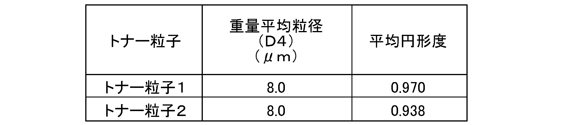
上記トナー粒子1に対して、図5に示す装置を用いて、外添混合処理を行った。
本実施例においては、図5に示す装置で、本体ケーシング11の内周部の径が130mmであり、処理空間19の容積が2.0×10⁻³m3の装置を用い、駆動部18の定格動力を5.5kWとし、攪拌部材13の形状を図6のものとした。そして、図6における攪拌部材13aと攪拌部材13bの重なり幅dを攪拌部材13の最大幅Dに対して0.25Dとし、攪拌部材13と本体ケーシング11内周とのクリアランスを3.0mmとした。
上記トナーA1の製造例において、表2、表3に示す、シリカ微粒子の種類及び添加部数、トナー粒子、外添装置、外添条件等へ変更した以外は同様にして、トナーA2乃至トナーA18を製造した。得られたトナーA2乃至トナーA18の外添条件、物性を表3にそれぞれ示す。
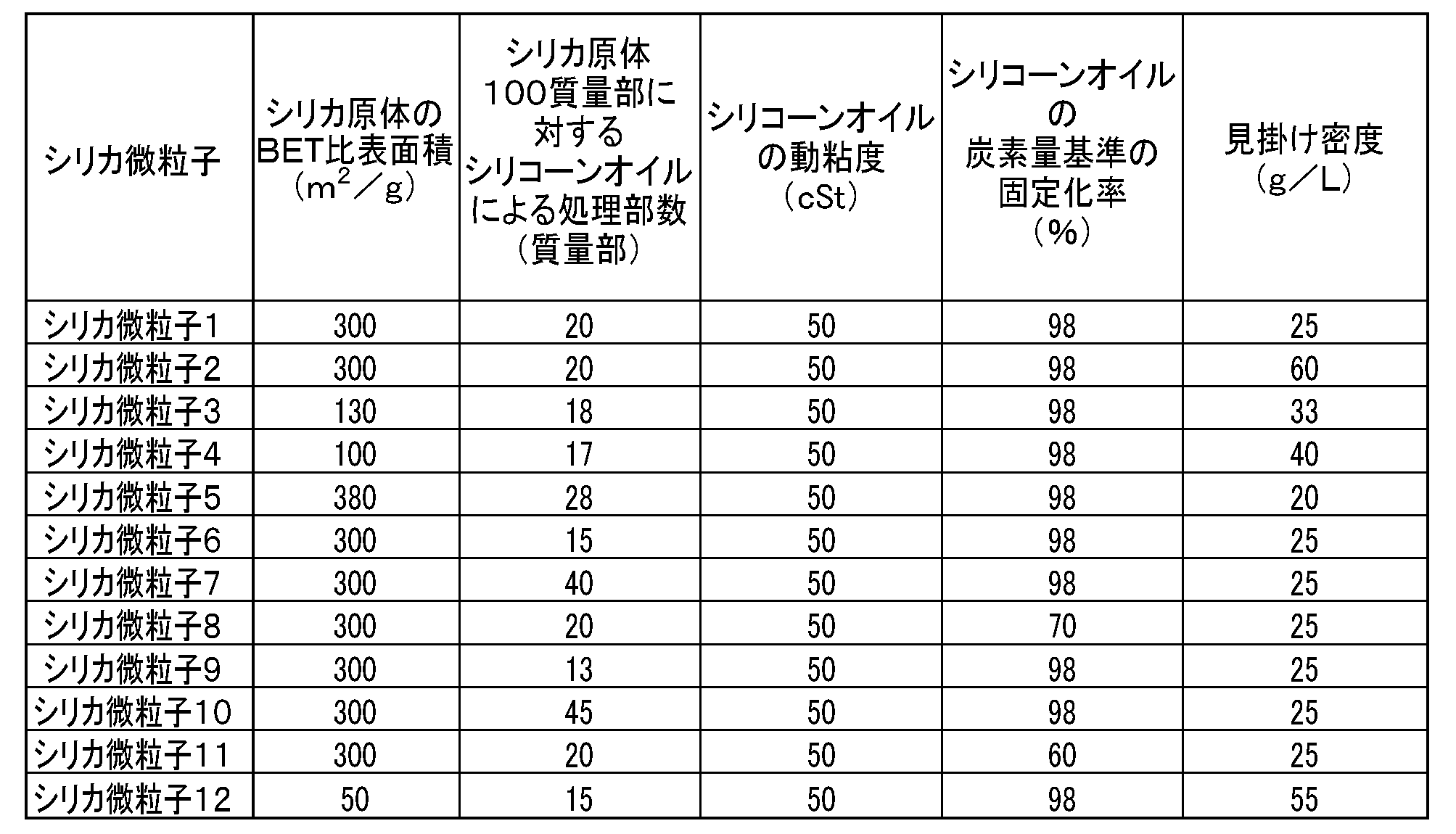
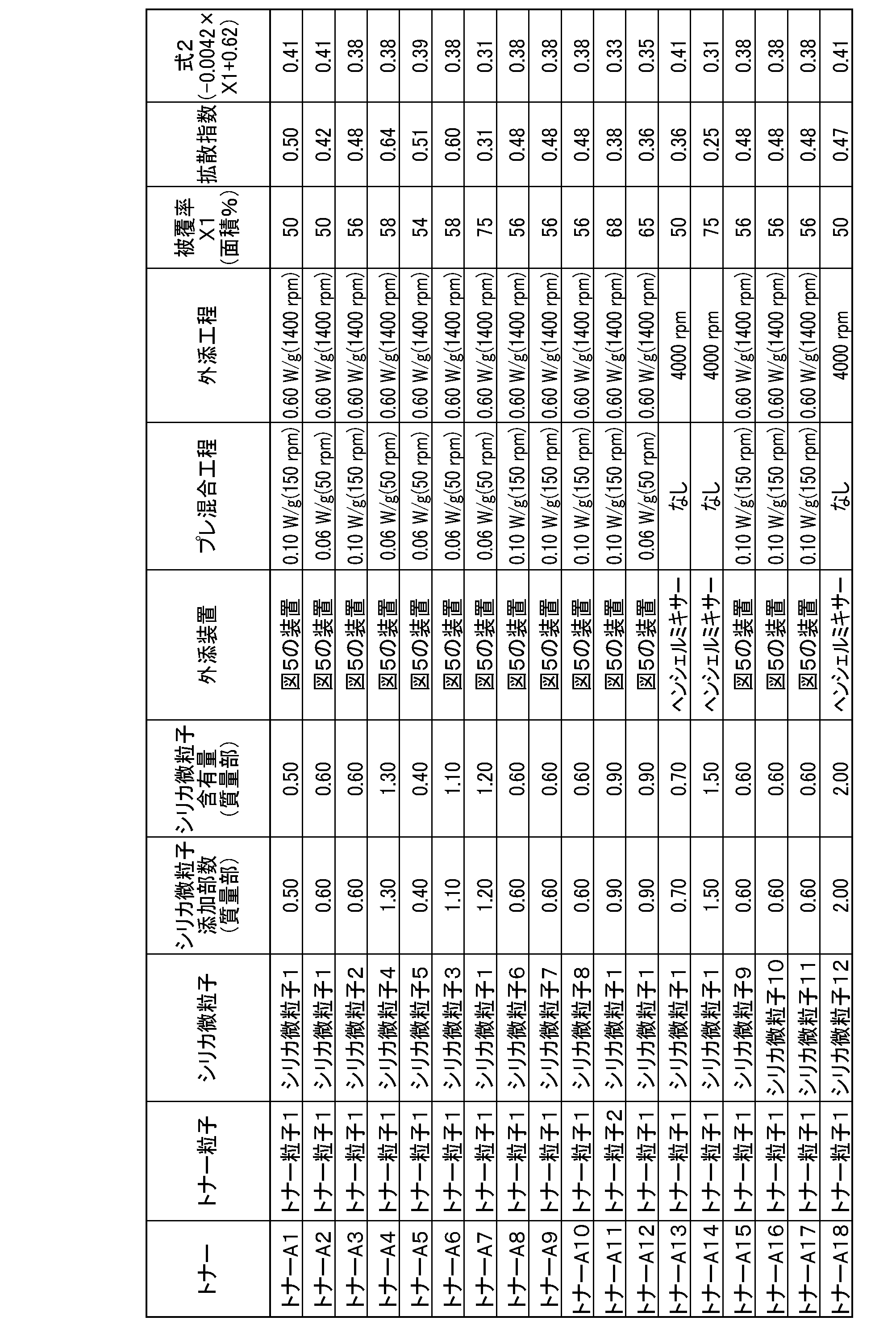
<各種パラメーターの測定方法>
〔樹脂粒子の断面の観察〕
樹脂粒子そのものについて、まず、樹脂粒子を光硬化型樹脂、例えば、可視光硬化性包埋樹脂(商品名:D-800、日新EM(株)社製、あるいは、商品名:Epok812セット、応研商事(株)社製)により包埋する。次に、ダイヤモンドナイフ(商品名:DiATOME CRYO DRY、DIATOME社製)を装着したウルトラミクロトーム(商品名:LEICA EM UCT、ライカ社製)、及び、クライオシステム(商品名:LEICA EM FCS、ライカ社製)を使用して、面出しをした後、樹脂粒子の中央(樹脂粒子の重心近辺が含まれるように)を切り出し、100nmの厚みの切片を作製する。この後、四酸化オスミウム、四酸化ルテニウム、あるいは、りんタングステン酸のいずれかの染色剤を使用して染色処理を行い、透過型電子顕微鏡(商品名:H-7100FA、日立製作所社製)にて、樹脂粒子の断面画像を撮影した。これを任意の粒子100個につき行った。この際、樹脂部分は白く、空孔部分は、黒く観察された。なお、包埋する樹脂、及び、染色剤は、樹脂粒子の材質により、適宜適切なものを選択して行う。この際、樹脂粒子の空孔が鮮明に確認できる組み合わせを選択する。下記に記載の本発明すべて製造例においては、可視光硬化型包埋樹脂D-800と四酸化ルテニウムを使用して観察することにより、空孔を鮮明に確認することができた。これを任意の粒子100個につき行った。この際、樹脂部分白く、空孔部分は若干灰色に観察された。
上記で得られた粒子断面画像に対し、空孔部分を含む領域を含めた総面積を算出し、この面積と等しい面積を持つ円の直径を求める。得られた直径から、計100個の平均粒径を算出し、これを樹脂粒子の体積平均粒径とする。
上記〔樹脂粒子の断面の観察〕で得られた粒子断面画像に対し、空孔部分を含む領域を含めた総面積に対し、上記断面画像において、空孔部分の総面積の割合を算出する。この作業を任意の樹脂粒子10個について行い、その平均を樹脂粒子の空孔率とする。
帯電部材の表面の任意の凸部で、帯電部材の表面に並行になるような、縦200μm横200μmの領域に亘って、帯電部材凸部頂点側から20nmずつ集束イオンビーム(商品名:FB-2000C、日立製作所社製)で切り出し、その断面画像を撮影する。そして同じ粒子を撮影した画像を20nm間隔で組み合わせ、立体的な粒子形状を算出する。この作業を、帯電部材表面の任意の100箇所について行う。
上記で〔帯電部材の表面に用いる樹脂層中に含まれる粒子の立体的な樹脂粒子形状の測定〕に記載の方法で得られた立体的な粒子形状において、空孔を含む領域を含めた総体積を算出する。これが、該樹脂粒子が中実粒子であると仮定したときの、該樹脂粒子の体積となる。そして、この体積と等しい体積を持つ球の直径を求める。100個の樹脂粒子に対して平均粒径を算出し、この平均を樹脂粒子の体積平均粒径とする。
上記〔帯電部材の表面に用いる樹脂層中に含まれる粒子の立体的な樹脂粒子形状の測定〕で記載の方法で得られた立体的な粒子形状から、樹脂粒子全体の空孔の総体積を算出し、前記樹脂粒子の空孔を含む領域を含めた総体積に対する割合を算出する。この作業を100個の粒子に対して行い、その平均を樹脂粒子全体の空孔率とする。
十点平均粗さRzjis、は、JIS B 0601-1994表面粗さの規格に準じて測定し、表面粗さ測定器(商品名:SE-3500、株式会社小坂研究所製)を用いて行う。十点平均粗さRzjisは、帯電部材を任意に6箇所測定し、その平均値である。測定に際し、カットオフ値は0.8mm、評価長さは8mmに設定する。
〔製造例B1〕 樹脂粒子B1の作製
脱イオン水400質量部に、第三リン酸カルシウム8.0質量部を添加し、水性媒体を調整した。次いで、重合単量体としてのメチルメタクリレート38.0質量部と、架橋性単量体としてのエチレングリコールジメタクリレート26.0質量部、第1の多孔化剤としてのノルマルへキサン34.1質量部、第2の多孔化剤としての酢酸エチル8.5質量部、及び、2,2’-アゾビスイソブチロニトリル0.3質量部を混合した、油性混合液を調整した。上記の油性混合液をホモミキサーにより、回転数2000rpmにて水性媒体に分散させた。その後、窒素置換した重合反応容器内へ仕込み、250rpmで撹拌しながら、60℃で6時間かけて懸濁重合を行い、多孔質の樹脂粒子とノルマルへキサン及び酢酸エチルを含む水性懸濁液を得た。この水性懸濁液に、ドデシルベンゼンスルホン酸ナトリウム0.4質量部を加え、ドデシルベンゼンスルホン酸ナトリウムの濃度を水に対し、0.1質量%に調整した。
油性混合液として、重合単量体、架橋性単量体、第1の多孔化剤、第2の多孔化剤を、表4に示すように変更し、且つ、ホモミキサーの回転数を表4に示すように変更した以外は、製造例B1と同様にして、樹脂粒子B2~B13を得た。得られた樹脂粒子B2~B13は、多孔質粒子であった。
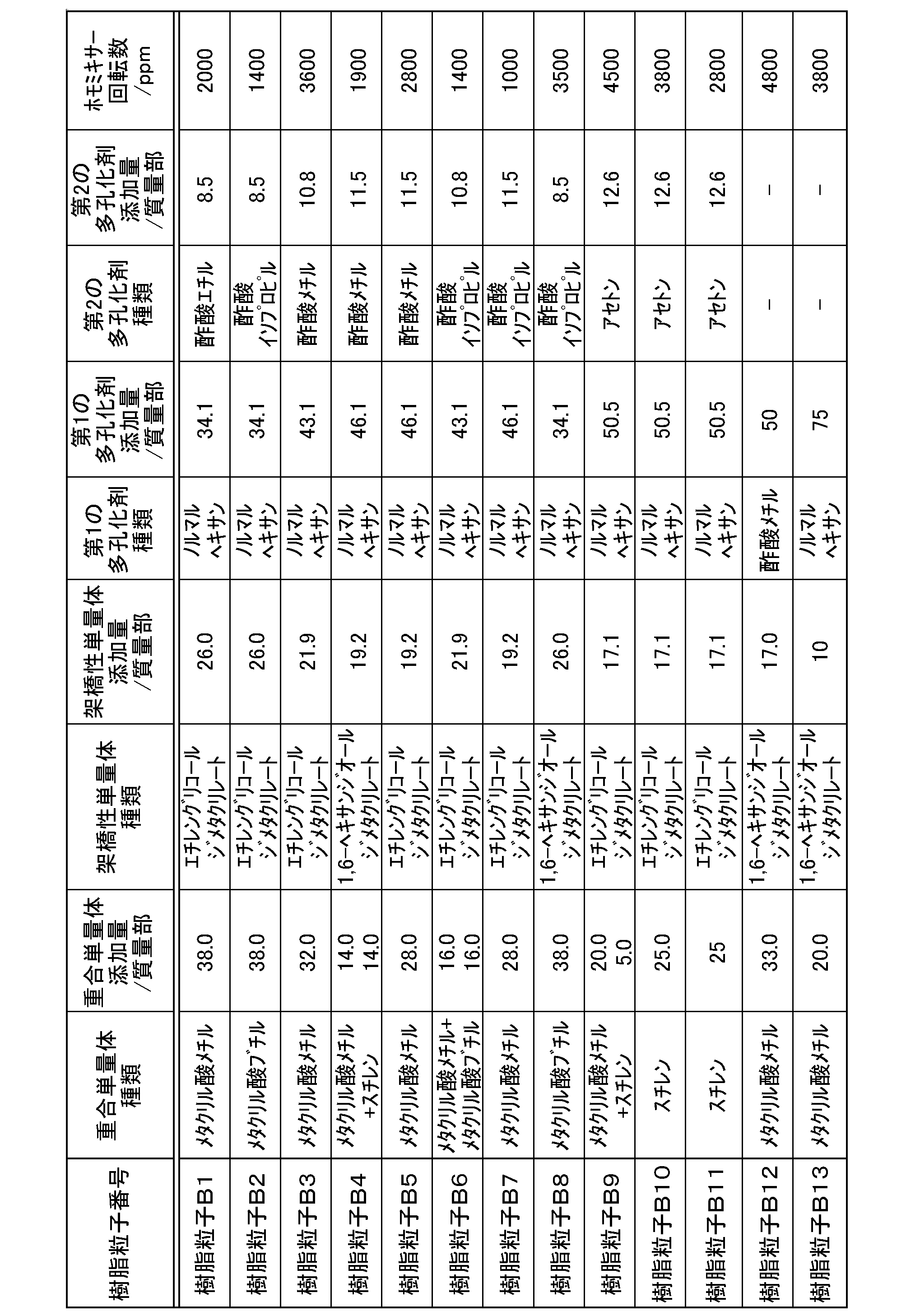
脱イオン水300質量部に、第三リン酸カルシウム10.5量部、及びドデシルベンゼンスルホン酸ナトリウム0.015質量部を加え、水性媒体を調製した。次いで、ラウリルメタクリレート65質量部、エチレングリコールジメタクリレート30質量部、ポリ(エチレングリコール‐テトラメチレングリコール)モノメタクリレート0.5質量部、及びアゾビスイソブチロニトリル0.5質量部を混合した、油性混合液を調製した。上記の油性混合液をホモミキサーにより、回転数4000rpmにて水性媒体中に分散させた。その後、窒素置換した重合反応容器内へ仕込み、250rpmで撹拌しながら、70℃で8時間かけて懸濁重合を行った。冷却後、得られた懸濁液に塩酸を加えリン酸カルシウムを分解し、更に、ろ過と水洗を繰り返した。80℃で5時間乾燥した後、音波式分級機により、解砕及び分級処理をおこない、平均粒径20.2μmの樹脂粒子B14を得た。前述した方法により、粒子の断面を観察したところ、樹脂粒子B14は、樹脂粒子内部に、3500nm程度の空孔径の空孔を複数有する空孔率5%程度の多中空粒子であった。
脱イオン水300質量部に、第三リン酸カルシウム10.5量部、ドデシルベンゼンスルホン酸ナトリウム0.015質量部を加え、水性媒体を調整した。次いで、ラウリルメタクリレート65質量部と、エチレングリコールジメタクリレート30質量部、ポリ(エチレングリコール‐テトラメチレングリコール)モノメタクリレート0.15質量部、アゾビスイソブチロニトリル0.5質量部を混合した、油性混合液を調整した。上記の油性混合液をホモミキサーにより、回転数4000rpmにて水性媒体に分散させた。その後、窒素置換した重合反応容器内へ仕込み、250rpmで撹拌しながら、70℃で8時間かけて懸濁重合を行った。冷却後、得られた懸濁液に塩酸を加えリン酸カルシウムを分解し、更に、ろ過と水洗を繰り返した。80℃で5時間乾燥した後、音波式分級機により、解砕及び分級処理をおこない、平均粒径15.2μmの樹脂粒子B15を得た。前述した方法により、粒子の断面を観察したところ、樹脂粒子B15は、樹脂粒子内部に、800nm程度の空孔を複数有する空孔率0.8%程度の多中空粒子であった。
架橋ポリメチルメタクリレート樹脂粒子(商品名:MBX-30、積水化成品工業(株)製)を分級処理し、体積平均粒径25.1μmの樹脂粒子B16を得た。前述した方法により、粒子の断面を観察したところ、本製造例の樹脂粒子B16は、内部に空孔を有していない、中実粒子であった。
脱イオン水300質量部に、第三リン酸カルシウム20量部、ドデシルベンゼンスルホン酸ナトリウム0.04質量部を加え、水性媒体を調製した。次いで、メチルアクリレート10質量部、スチレン81質量部、ジビニルベンゼン15質量部と、アゾビスイソブチロニトリル0.8質量部、及び、界面活性剤(商品名:ソルバース26000、ソルバース社製)1.2質量部を混合した、油性混合液を調製した。上記の油性混合液をホモミキサーにより、回転数4000rpmにて水性媒体に分散させた。その後、窒素置換した重合反応容器内へ仕込み、250rpmで撹拌しながら、70℃で8時間かけて懸濁重合を行った。冷却後、得られた懸濁液に塩酸を加えリン酸カルシウムを分解し、更に、ろ過と水洗を繰り返した。80℃で5時間乾燥した後、音波式分級機により、解砕及び分級処理を行い、平均粒径20.2μmの樹脂粒子B17を得た。前述した方法により、粒子の断面を観察したところ、この粒子は、粒子内部に1つの中空部を有する粒子(以下、「単中空粒子」と称す)であった。尚、中空部は、5200nm程度の空孔径を有し、空孔率は、5%程度であった。
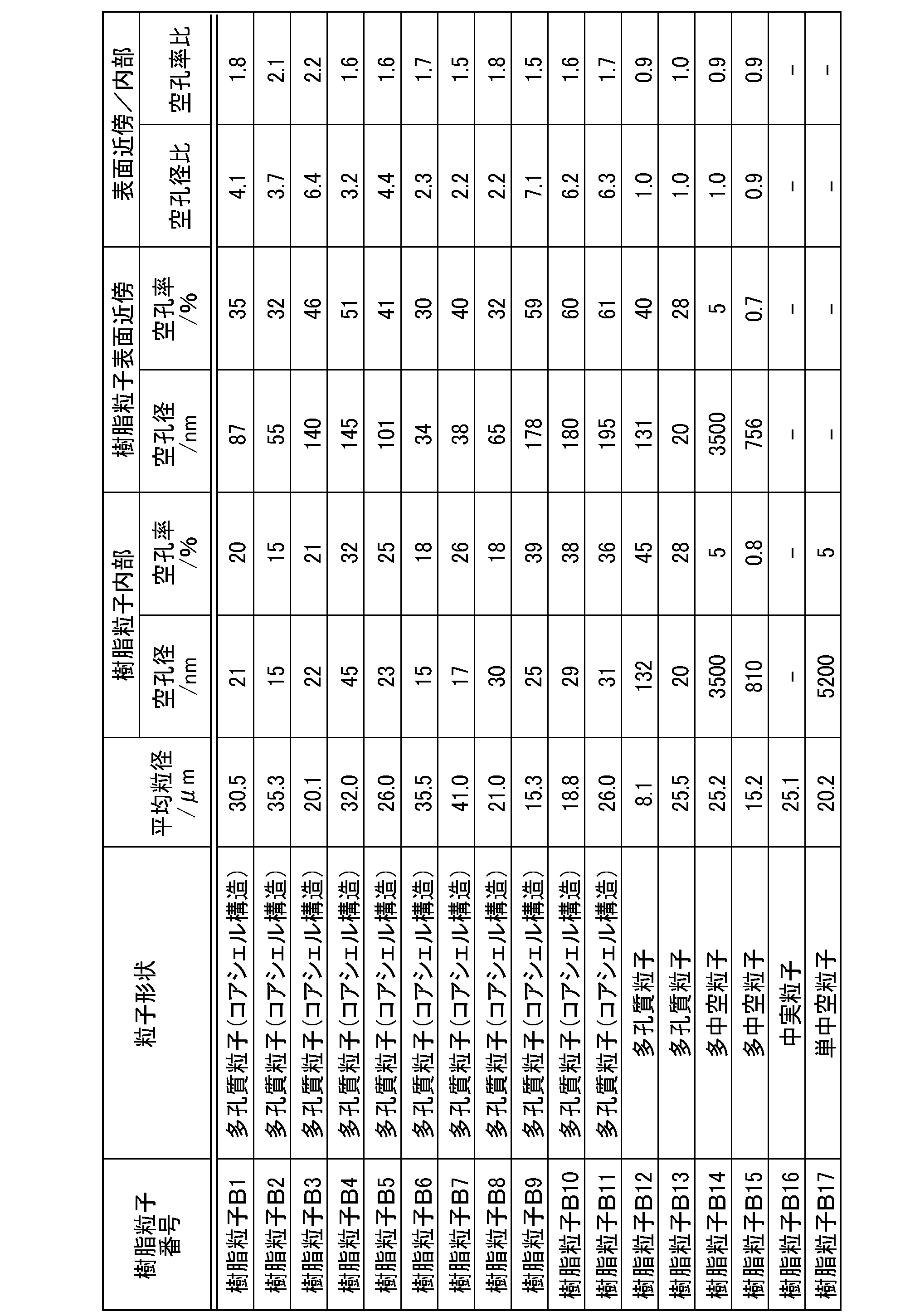
〔製造例C1〕 複合導電性微粒子の作製
シリカ粒子(平均粒径15nm、体積抵抗率1.8×10¹²Ω・cm)7.0kgに、メチルハイドロジェンポリシロキサン140gを、エッジランナーを稼動させながら添加し、588N/cm(60kg/cm)の線荷重で30分間混合撹拌を行った。この時の撹拌速度は22rpmであった。その中に、カーボンブラック(商品名:#52、三菱化学(株)製)7.0kgを、エッジランナーを稼動させながら10分間かけて添加し、更に588N/cm(60kg/cm)の線荷重で60分間混合撹拌を行った。このようにしてメチルハイドロジェンポリシロキサンで被覆されてシリカ粒子の表面にカーボンブラックを付着させた後、乾燥機を用いて80℃で60分間乾燥を行い、複合導電性微粒子を作製した。この時の撹拌速度は22rpmであった。なお、得られた複合導電性微粒子は、平均粒径が15nmであり、体積抵抗率は1.1×102Ω・cmであった。
針状ルチル型酸化チタン粒子(平均粒径15nm、縦:横=3:1、体積抵抗率2.3×10¹⁰Ω・cm)1000gに、表面処理剤としてイソブチルトリメトキシシラン110g及び溶媒としてトルエン3000gを配合してスラリーを調製した。このスラリーを、撹拌機で30分間混合した後、有効内容積の80%が平均粒子径0.8mmのガラスビーズで充填されたビスコミルに供給し、温度35±5℃で湿式解砕処理を行った。湿式解砕処理して得たスラリーを、ニーダーを用いて減圧蒸留(バス温度:110℃、製品温度:30~60℃、減圧度:100Torr)によりトルエンを除去し、120℃で2時間表面処理剤の焼付け処理を行った。焼付け処理した粒子を室温まで冷却した後、ピンミルを用いて粉砕して、表面処理酸化チタン粒子を作製した。なお、得られた表面処理酸化チタン粒子は、平均粒径が15nmであり、体積抵抗率は5.2×10¹⁵Ω・cmであった。
〔製造例D1〕 帯電部材D1の作製
(導電性基体の作製)
直径6mm、長さ244mmのステンレス鋼製の基体に、カーボンブラックを10質量%含有させた熱硬化性接着剤を塗布し、乾燥したものを導電性基体として使用した。
エピクロルヒドリンゴム(EO-EP-AGC三元共化合物、EO/EP/AGE=73mol%/23mol%/4mol%)100質量部に対し下記表6に示す他の8種類の材料を加えて、50℃に調節した密閉型ミキサーで10分間混練して、原料コンパウンドを調製した。
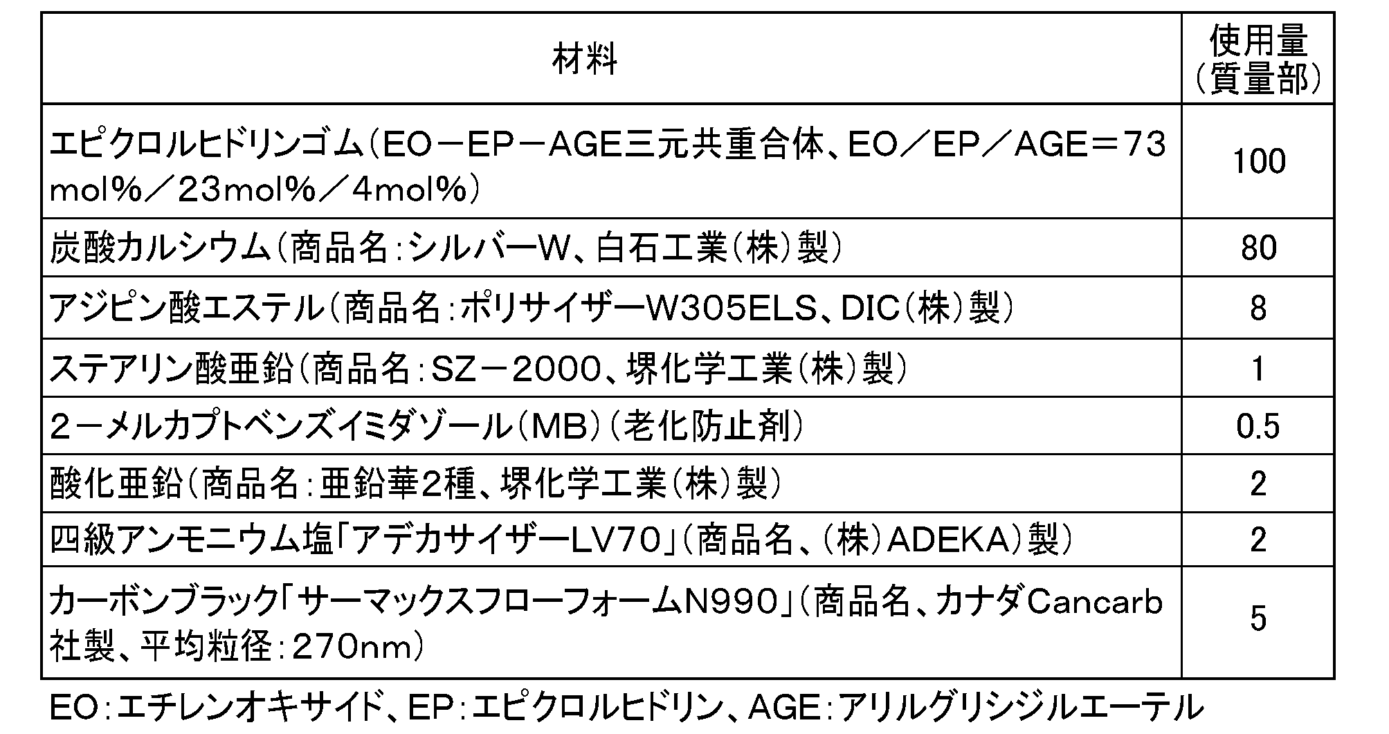
クロスヘッドを具備する押出成形装置を用いて、前記導電性基体を中心軸として、その外周部を同軸円筒状に前記導電性ゴム組成物によって被覆し、ゴムローラを得た。被覆したゴム組成物の厚みは、1.75mmに調整した。
第一段階の分散として、カプロラクトン変性アクリルポリオール溶液(商品名:プラクセルDC2016、(株)ダイセル製)にメチルイソブチルケトンを加え、固形分が12質量%となるように調整した。この溶液834質量部(アクリルポリオール固形分100質量部)に対して、下記表7の成分(1)の欄に示す導電性粒子としての複合導電性微粒子及び無機粒子としての表面処理酸化チタン粒子及び変性ジメチルシリコーンオイルを加え、混合溶液を調製した。次いで、内容積450mLのガラス瓶中に上記混合溶液188.5gを、メディアとしての平均粒径0.8mmのガラスビーズ200gと共に入れ、ペイントシェーカー分散機を用いて20時間分散した。
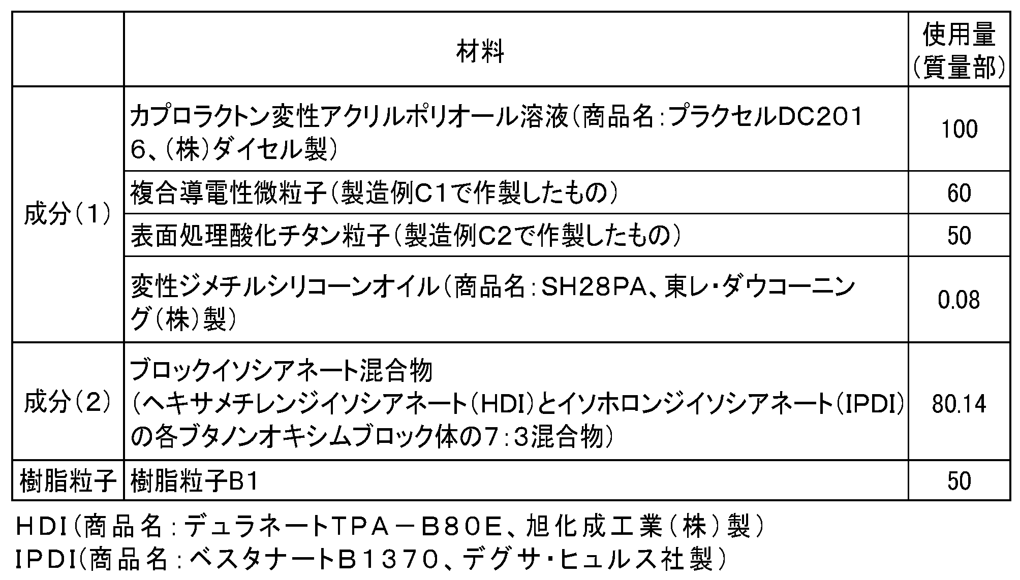
前記弾性ローラを、その長手方向を鉛直方向にして、前記塗布液中に浸漬してディッピング法で塗工した。浸漬時間は9秒間、引き上げ速度は初期速度が20mm/s、最終速度は2mm/s、その間は時間に対して直線的に速度を変化させた。得られた塗工物を23℃で30分間風乾した後、熱風循環乾燥機にて温度80℃で1時間、更に温度160℃で1時間乾燥して塗膜を硬化させて、弾性層の外周部に樹脂層が形成された帯電部材D1を得た。樹脂層の膜厚は、5.2μmであった。なお、樹脂層の膜厚は、樹脂粒子が存在しない箇所において測定した。
帯電部材D2~D27を作製するための樹脂層用塗布液d2~d27の材料及び物性を下記表8に記載する。下記表8に記載の材料に変更した以外は、製造例D1と同様の方法で帯電部材D2~D27を作製した。完成した帯電部材の物性値に関して、下記表9にまとめた。

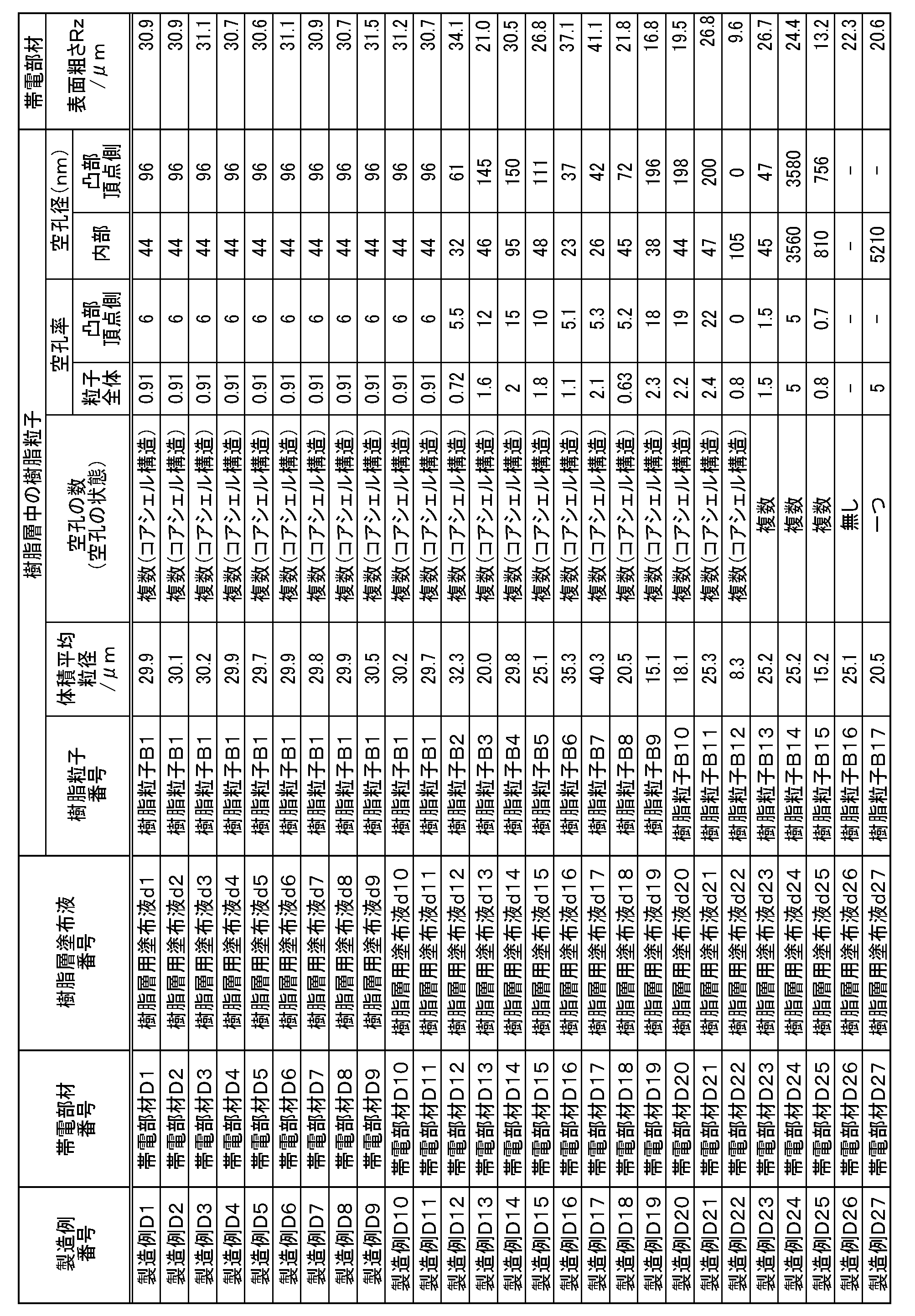
〔耐久試験〕
図9に示す構成を有する画像形成装置であるモノクロレーザープリンタ(商品名:LBP6300、キヤノン(株)製)を、370mm/secのプロセススピードに改造し、更に、外部より、帯電部材に電圧を印加した。印加する電圧は、交流電圧として、ピークピーク電圧(Vpp)が1600V、周波数(f)が1350Hz、直流電圧(Vdc)が-560Vをとした。画像の解像度は、600dpiで出力した。なお、プロセスカートリッジとして、上記プリンタ用のプロセスカートリッジを用いた。
ランク1;横スジ状画像(ポチ状画像)は発生しない。
ランク2;軽微な横スジ状画像(ポチ状画像)が認められるのみである。
ランク3;一部に、横スジ状画像(ポチ状画像)が帯電ローラのピッチで確認されるが、実用画像上問題無い。
ランク4;横スジ状画像(ポチ状画像)が目立ち、画質の低下が認められる。
また、耐久試験後の帯電部材の表面を目視により観察し、その表面の汚れについて、下記基準で判定した。評価結果を表10に示す。
ランク1;全く汚れが存在しない。
ランク2;ごくまれに汚れが存在する。
ランク3;まれに汚れが存在する。
ランク4;多量に汚れが存在する。
ガラス板(縦300mm、横240mm、厚み4.5mm)の表面上に5μmのITO膜を形成し、更に、その表面に、電荷輸送層のみを17μmに成膜した。図14で示すように、上記成膜後のガラス板45表面側から、帯電部材14を、一端で4.9N、両端で合計9.8Nのバネによる押し圧力で当接できるような工具を作製し、更に、ガラス板45を200mm/sで走査できるようにした。上記ガラス板45を感光体に見立て、当接部下側(ガラス板45表面と反対側)から高速度ゲート(製品名:I.I.ユニットC9527-2、浜松ホトニクス(株)社製)を介して、高速度カメラ(製品名:FASTCAM-SA1.1、浜松ホトニクス(株)社製)で観察することにより、帯電部材7のニップ内放電強度を確認した。帯電部材7に印加する電圧は、交流電圧として、ピークピーク電圧(Vpp)が1600V、周波数(f)が1350Hz、直流電圧(Vdc)が-560Vをとした。測定環境は、低温低湿環境下(7.5℃/30%RH環境)とした。
ランク1;ニップ内全域に、放電が安定して確認される。
ランク2;ニップ内に、放電が不安定な部分が確認されるが、問題無い。
ランク3;ニップ内全域に、放電が不安定である。
ランク4;ニップ内全域に、放電が微弱で、不安定である。
トナーと帯電部材の組み合わせを表10に示すように変更した以外は、実施例1と同様にして評価を行った。結果を表10に示す。
トナーと帯電部材の組み合わせを表10に示すように変更した以外は、実施例1と同様にして評価を行った。結果を表10に示す。いずれの比較例においても、耐久試験後の帯電部材表面には多量の汚れが存在し、ニップ内放電も微弱なものとなり、横スジ状画像及びポチ状画像が目立ち、画質の低下が認められた。

2 樹脂層
3 樹脂粒子
4 弾性層
5 接着剤
Claims (16)
- 感光体と、該感光体を帯電部材によって帯電するための帯電手段と、帯電された該感光体の表面に静電潜像を形成するための露光手段と、静電潜像が形成された該感光体にトナーを供給してトナー像を該感光体の表面に形成するための現像手段とを有する画像形成装置であって、
該帯電部材は、導電性基体と導電性の樹脂層を有する帯電部材であって、
該樹脂層は、結着樹脂Cと、該帯電部材の表面を粗面化させている樹脂粒子とを含み、該樹脂粒子の内部は、複数の空孔を有し、
該帯電部材の表面は、該樹脂粒子に由来する複数の凸部を有し、
該トナーは、結着樹脂T及び着色剤を含有するトナー粒子と、無機微粒子とを含有するトナーであって、
該無機微粒子がシリカ微粒子であり、
該トナーは、該シリカ微粒子をトナー粒子100質量部あたり0.40質量部以上、1.50質量部以下含有し、
該シリカ微粒子は、シリカ原体100質量部に対して、15.0質量部以上40.0質量部以下のシリコーンオイルによって処理されており、該シリコーンオイルの炭素量基準の固定化率(%)が70%以上であり、
X線光電子分光装置(ESCA)により求めた、該トナー表面の該シリカ微粒子による被覆率X1が50.0面積%以上75.0面積%以下であり、該シリカ微粒子による理論被覆率をX2としたとき、下記式1で示される拡散指数が下記式2を満足するトナーであることを特徴とする画像形成装置。
(式1)拡散指数=X1/X2
(式2)拡散指数≧-0.0042×X1+0.62 - 該樹脂層は、カーボンブラック及び無機粒子を有する凝集体を含むことを特徴とする請求項1に記載の画像形成装置。
- 該凝集体は、2種以上の無機粒子を含むことを特徴とする請求項1または2に記載の画像形成装置。
- 該樹脂粒子の全体の空孔率が、2.5体積%以下であることを特徴とする請求項1乃至3のいずれか一項に記載の画像形成装置。
- 該樹脂粒子が、該樹脂粒子が空孔を有しない中実粒子であると仮定したときの該中実粒子の11体積%を占める領域であって該導電性基体からの距離が最も離れた領域における空孔率V11が5体積%以上、20体積%以下であることを特徴とする請求項4に記載の画像形成装置。
- 該空孔率V11が、5.5体積%以上、15体積%以下である請求項5に記載の画像形成装置。
- 該樹脂粒子の、該樹脂粒子が空孔を有しない中実粒子であると仮定したときの該中実
粒子内の11体積%を占める領域であって該導電性基体からの距離が最も離れた領域における空孔径R11が、平均空孔径で、30nm以上、200nm以下であることを特徴とする請求項5又は6に記載の画像形成装置。 - 該空孔径R11が、平均空孔径で、60nm以上、150nm以下である請求項7に記載の画像形成装置。
- 該帯電部材の十点平均表面粗さ(Rzjis)が、8μm以上、100μm以下であることを特徴とする請求項1~8のいずれか一項に記載の画像形成装置。
- 該帯電部材の表面の凹凸平均間隔(RSm)が、20μm以上、300μm以下であることを特徴とする請求項1~9のいずれか一項に記載の画像形成装置。
- 該導電性粒子の平均粒径が、5nm以上、300nm以下であることを特徴とする請求項1~10のいずれか一項に記載の画像形成装置。
- 該樹脂粒子が、アクリル樹脂、スチレン樹脂又はスチレンアクリル樹脂からなる粒子であることを特徴とする請求項1~11のいずれか一項に記載の画像形成装置。
- 該樹脂層における樹脂粒子の含有量が、前記結着樹脂Cの100質量部に対して、2質量部以上、100質量部以下であることを特徴とする請求項1~12のいずれか一項に記載の画像形成装置。
- 該樹脂層における樹脂粒子の含有量が、前記結着樹脂Cの100質量部に対して、5質量部以上、80質量部以下であることを特徴とする請求項13に記載の画像形成装置。
- 該樹脂粒子の体積平均粒径が、10μm以上、50μm以下であることを特徴とする請求項1~14のいずれか一項に記載の画像形成装置。
- 該感光体、該帯電手段及び該現像手段を一体に支持し、請求項1乃至15のいずれか一項に記載の画像形成装置から着脱可能に構成されていることを特徴とするプロセスカートリッジ。
Priority Applications (4)
| Application Number | Priority Date | Filing Date | Title |
|---|---|---|---|
| PCT/JP2013/067722 WO2014207876A1 (ja) | 2013-06-27 | 2013-06-27 | 画像形成装置及びプロセスカートリッジ |
| CN201380077821.9A CN105339847B (zh) | 2013-06-27 | 2013-06-27 | 图像形成设备和处理盒 |
| JP2015523761A JP6157619B2 (ja) | 2013-06-27 | 2013-06-27 | 画像形成装置及びプロセスカートリッジ |
| US14/316,040 US9335650B2 (en) | 2013-06-27 | 2014-06-26 | Image forming apparatus and process cartridge utilizing a porous charging member |
Applications Claiming Priority (1)
| Application Number | Priority Date | Filing Date | Title |
|---|---|---|---|
| PCT/JP2013/067722 WO2014207876A1 (ja) | 2013-06-27 | 2013-06-27 | 画像形成装置及びプロセスカートリッジ |
Publications (1)
| Publication Number | Publication Date |
|---|---|
| WO2014207876A1 true WO2014207876A1 (ja) | 2014-12-31 |
Family
ID=52115725
Family Applications (1)
| Application Number | Title | Priority Date | Filing Date |
|---|---|---|---|
| PCT/JP2013/067722 Ceased WO2014207876A1 (ja) | 2013-06-27 | 2013-06-27 | 画像形成装置及びプロセスカートリッジ |
Country Status (4)
| Country | Link |
|---|---|
| US (1) | US9335650B2 (ja) |
| JP (1) | JP6157619B2 (ja) |
| CN (1) | CN105339847B (ja) |
| WO (1) | WO2014207876A1 (ja) |
Cited By (6)
| Publication number | Priority date | Publication date | Assignee | Title |
|---|---|---|---|---|
| JP2015212812A (ja) * | 2014-04-18 | 2015-11-26 | キヤノン株式会社 | 帯電部材、プロセスカートリッジ及び電子写真装置 |
| JP2016038592A (ja) * | 2014-08-07 | 2016-03-22 | キヤノン株式会社 | トナー及びトナーの製造方法 |
| JP2016126220A (ja) * | 2015-01-07 | 2016-07-11 | キヤノン株式会社 | トナーの製造方法 |
| JP2016139063A (ja) * | 2015-01-29 | 2016-08-04 | キヤノン株式会社 | トナー |
| WO2018096714A1 (ja) * | 2016-11-22 | 2018-05-31 | エスプリンティンソリューション株式会社 | 帯電部材 |
| US11686208B2 (en) | 2020-02-06 | 2023-06-27 | Rolls-Royce Corporation | Abrasive coating for high-temperature mechanical systems |
Families Citing this family (10)
| Publication number | Priority date | Publication date | Assignee | Title |
|---|---|---|---|---|
| WO2015040660A1 (ja) * | 2013-09-20 | 2015-03-26 | キヤノン株式会社 | 帯電部材とその製造方法、プロセスカートリッジ及び電子写真装置 |
| US9360789B1 (en) * | 2014-11-28 | 2016-06-07 | Canon Kabushiki Kaisha | Member for electrophotography, process cartridge and image forming apparatus |
| EP3413136B1 (en) * | 2016-02-01 | 2021-11-10 | Bridgestone Corporation | Charging roller |
| JP6658169B2 (ja) * | 2016-03-18 | 2020-03-04 | 富士ゼロックス株式会社 | 電子写真感光体用導電性支持体、電子写真感光体、プロセスカートリッジ、画像形成装置、及び電子写真感光体用導電性支持体の製造方法 |
| US10678158B2 (en) * | 2016-09-26 | 2020-06-09 | Canon Kabushiki Kaisha | Electro-conductive member for electrophotography, process cartridge, and electrophotographic image forming apparatus |
| JP6976774B2 (ja) * | 2016-09-27 | 2021-12-08 | キヤノン株式会社 | 電子写真用導電性部材、プロセスカートリッジおよび電子写真画像形成装置 |
| US10268132B2 (en) * | 2017-06-15 | 2019-04-23 | Canon Kabushiki Kaisha | Charging roller, cartridge, image forming apparatus and manufacturing method of the charging roller |
| TWI709020B (zh) * | 2018-03-30 | 2020-11-01 | 日商京瓷股份有限公司 | 電感用芯、電子筆用芯體部、電子筆及輸入裝置 |
| CN113195909B (zh) * | 2018-12-17 | 2023-06-02 | 株式会社亚科迈 | 充电辊和图像形成装置 |
| EP4177312A4 (en) * | 2020-07-02 | 2025-05-14 | Toyo Aluminium Kabushiki Kaisha | COMPOSITE PIGMENT, THERMOPLASTIC RESIN COMPOSITION THEREOF AND MOULDED BODIES |
Citations (5)
| Publication number | Priority date | Publication date | Assignee | Title |
|---|---|---|---|---|
| JP2006154442A (ja) * | 2004-11-30 | 2006-06-15 | Canon Inc | 帯電部材及び帯電装置 |
| JP2011053429A (ja) * | 2009-09-01 | 2011-03-17 | Fuji Xerox Co Ltd | 帯電部材、プロセスカートリッジおよび画像形成装置 |
| JP2011107375A (ja) * | 2009-11-17 | 2011-06-02 | Canon Inc | 画像形成方法 |
| JP2013047754A (ja) * | 2011-08-29 | 2013-03-07 | Canon Inc | トナー |
| JP2013134447A (ja) * | 2011-12-27 | 2013-07-08 | Canon Inc | 磁性トナー |
Family Cites Families (19)
| Publication number | Priority date | Publication date | Assignee | Title |
|---|---|---|---|---|
| US6477344B1 (en) | 1999-05-28 | 2002-11-05 | Matsushita Electric Industrial Co., Ltd. | Image forming apparatus, transfer belt unit, cleaning device and cleaner unit used for image forming apparatus |
| JP2003316112A (ja) * | 2002-04-19 | 2003-11-06 | Canon Inc | 帯電部材、画像形成装置及びプロセスカートリッジ |
| JP2006107375A (ja) | 2004-10-08 | 2006-04-20 | Canon Inc | 文書管理システム、文書管理方法、プログラムおよび記憶媒体 |
| US20060222982A1 (en) * | 2005-03-31 | 2006-10-05 | Sakiko Fujikawa | Developer and image forming method |
| JP5173249B2 (ja) * | 2007-05-01 | 2013-04-03 | キヤノン株式会社 | 帯電部材、プロセスカートリッジ及び電子写真画像形成装置 |
| JP5612805B2 (ja) * | 2008-01-24 | 2014-10-22 | 東海ゴム工業株式会社 | 帯電ロール |
| JP4590486B2 (ja) | 2008-05-16 | 2010-12-01 | キヤノン株式会社 | 疎水性無機微粒子及びトナー |
| WO2010050615A1 (ja) * | 2008-10-31 | 2010-05-06 | キヤノン株式会社 | 帯電部材、プロセスカートリッジ及び電子写真装置 |
| CN105388725B (zh) | 2010-04-30 | 2018-01-30 | 佳能株式会社 | 充电构件、处理盒和电子照相设备 |
| JP5875264B2 (ja) | 2010-07-13 | 2016-03-02 | キヤノン株式会社 | 帯電部材の製造方法 |
| JP5533454B2 (ja) * | 2010-08-31 | 2014-06-25 | 株式会社リコー | トナー及び現像剤 |
| JP5694760B2 (ja) | 2010-12-28 | 2015-04-01 | キヤノン株式会社 | 帯電ローラ |
| US9063443B2 (en) * | 2012-05-28 | 2015-06-23 | Canon Kabushiki Kaisha | Magnetic carrier and two-component developer |
| JP6150631B2 (ja) * | 2012-06-27 | 2017-06-21 | キヤノン株式会社 | トナーの製造方法 |
| JP5777665B2 (ja) * | 2013-01-29 | 2015-09-09 | キヤノン株式会社 | 帯電部材、プロセスカートリッジ及び電子写真装置 |
| CN104956265B (zh) * | 2013-01-29 | 2017-08-15 | 佳能株式会社 | 电子照相处理盒和电子照相设备 |
| US9098006B2 (en) * | 2013-04-03 | 2015-08-04 | Canon Kabushiki Kaisha | Roller member for electrophotography, process cartridge and electrophotographic apparatus |
| JP6165249B2 (ja) * | 2013-06-27 | 2017-07-19 | キヤノン株式会社 | 画像形成装置 |
| US9256153B2 (en) * | 2014-04-18 | 2016-02-09 | Canon Kabushiki Kaisha | Charging member, process cartridge and electrophotographic apparatus |
-
2013
- 2013-06-27 WO PCT/JP2013/067722 patent/WO2014207876A1/ja not_active Ceased
- 2013-06-27 JP JP2015523761A patent/JP6157619B2/ja not_active Expired - Fee Related
- 2013-06-27 CN CN201380077821.9A patent/CN105339847B/zh not_active Expired - Fee Related
-
2014
- 2014-06-26 US US14/316,040 patent/US9335650B2/en active Active
Patent Citations (5)
| Publication number | Priority date | Publication date | Assignee | Title |
|---|---|---|---|---|
| JP2006154442A (ja) * | 2004-11-30 | 2006-06-15 | Canon Inc | 帯電部材及び帯電装置 |
| JP2011053429A (ja) * | 2009-09-01 | 2011-03-17 | Fuji Xerox Co Ltd | 帯電部材、プロセスカートリッジおよび画像形成装置 |
| JP2011107375A (ja) * | 2009-11-17 | 2011-06-02 | Canon Inc | 画像形成方法 |
| JP2013047754A (ja) * | 2011-08-29 | 2013-03-07 | Canon Inc | トナー |
| JP2013134447A (ja) * | 2011-12-27 | 2013-07-08 | Canon Inc | 磁性トナー |
Cited By (7)
| Publication number | Priority date | Publication date | Assignee | Title |
|---|---|---|---|---|
| JP2015212812A (ja) * | 2014-04-18 | 2015-11-26 | キヤノン株式会社 | 帯電部材、プロセスカートリッジ及び電子写真装置 |
| JP2016038592A (ja) * | 2014-08-07 | 2016-03-22 | キヤノン株式会社 | トナー及びトナーの製造方法 |
| JP2016126220A (ja) * | 2015-01-07 | 2016-07-11 | キヤノン株式会社 | トナーの製造方法 |
| JP2016139063A (ja) * | 2015-01-29 | 2016-08-04 | キヤノン株式会社 | トナー |
| WO2018096714A1 (ja) * | 2016-11-22 | 2018-05-31 | エスプリンティンソリューション株式会社 | 帯電部材 |
| US10599062B2 (en) | 2016-11-22 | 2020-03-24 | Hewlett-Packard Development Company L.P. | Charging member |
| US11686208B2 (en) | 2020-02-06 | 2023-06-27 | Rolls-Royce Corporation | Abrasive coating for high-temperature mechanical systems |
Also Published As
| Publication number | Publication date |
|---|---|
| CN105339847A (zh) | 2016-02-17 |
| US20150003874A1 (en) | 2015-01-01 |
| US9335650B2 (en) | 2016-05-10 |
| JP6157619B2 (ja) | 2017-07-05 |
| CN105339847B (zh) | 2017-12-22 |
| JPWO2014207876A1 (ja) | 2017-02-23 |
Similar Documents
| Publication | Publication Date | Title |
|---|---|---|
| JP6157619B2 (ja) | 画像形成装置及びプロセスカートリッジ | |
| JP6391458B2 (ja) | 現像装置、現像方法、画像形成装置、および画像形成方法 | |
| JP6120698B2 (ja) | プロセスカートリッジ | |
| JP6231875B2 (ja) | 現像装置、現像方法、画像形成装置、および画像形成方法 | |
| US11360405B2 (en) | Electrophotographic apparatus, process cartridge and cartridge set | |
| JP6165249B2 (ja) | 画像形成装置 | |
| KR101667175B1 (ko) | 대전 부재, 프로세스 카트리지 및 전자 사진 장치 | |
| JP7401255B2 (ja) | 電子写真装置、プロセスカートリッジ、及びカートリッジセット | |
| US11061342B2 (en) | Electrophotographic apparatus, process cartridge and cartridge set | |
| JP7336351B2 (ja) | 電子写真装置、プロセスカートリッジ、及びカートリッジセット | |
| JP6732486B2 (ja) | プロセスカートリッジ | |
| JP5408932B2 (ja) | 画像形成方法 | |
| CN110865529B (zh) | 图像形成设备 | |
| JP6100106B2 (ja) | トナー | |
| JP7030537B2 (ja) | 電子写真用の帯電部材、プロセスカートリッジおよび電子写真画像形成装置 | |
| JP2021067941A (ja) | 電子写真装置、プロセスカートリッジ、及びカートリッジセット | |
| JP6946149B2 (ja) | 電子写真用ローラ、プロセスカートリッジ及び電子写真画像形成装置 |
Legal Events
| Date | Code | Title | Description |
|---|---|---|---|
| WWE | Wipo information: entry into national phase |
Ref document number: 201380077821.9 Country of ref document: CN |
|
| 121 | Ep: the epo has been informed by wipo that ep was designated in this application |
Ref document number: 13888391 Country of ref document: EP Kind code of ref document: A1 |
|
| ENP | Entry into the national phase |
Ref document number: 2015523761 Country of ref document: JP Kind code of ref document: A |
|
| NENP | Non-entry into the national phase |
Ref country code: DE |
|
| 122 | Ep: pct application non-entry in european phase |
Ref document number: 13888391 Country of ref document: EP Kind code of ref document: A1 |