WO2014203416A1 - 靴紐巻取用リール - Google Patents
靴紐巻取用リール Download PDFInfo
- Publication number
- WO2014203416A1 WO2014203416A1 PCT/JP2013/078117 JP2013078117W WO2014203416A1 WO 2014203416 A1 WO2014203416 A1 WO 2014203416A1 JP 2013078117 W JP2013078117 W JP 2013078117W WO 2014203416 A1 WO2014203416 A1 WO 2014203416A1
- Authority
- WO
- WIPO (PCT)
- Prior art keywords
- shoelace
- shoelace winding
- reel
- winding drum
- peripheral surface
- Prior art date
Links
- 238000004804 winding Methods 0.000 title claims abstract description 144
- 230000002093 peripheral effect Effects 0.000 claims abstract description 27
- 238000003780 insertion Methods 0.000 claims description 25
- 230000037431 insertion Effects 0.000 claims description 25
- 239000011347 resin Substances 0.000 claims description 6
- 229920005989 resin Polymers 0.000 claims description 6
- 239000002184 metal Substances 0.000 claims description 5
- 239000002131 composite material Substances 0.000 claims description 4
- 230000008878 coupling Effects 0.000 abstract 1
- 238000010168 coupling process Methods 0.000 abstract 1
- 238000005859 coupling reaction Methods 0.000 abstract 1
- 238000003860 storage Methods 0.000 description 11
- 238000000034 method Methods 0.000 description 7
- 210000000078 claw Anatomy 0.000 description 6
- 239000000463 material Substances 0.000 description 4
- 239000004677 Nylon Substances 0.000 description 3
- 238000012423 maintenance Methods 0.000 description 3
- 229920001778 nylon Polymers 0.000 description 3
- 229920006324 polyoxymethylene Polymers 0.000 description 2
- 239000010935 stainless steel Substances 0.000 description 2
- 229910001220 stainless steel Inorganic materials 0.000 description 2
- 229920002725 thermoplastic elastomer Polymers 0.000 description 2
- 229910000975 Carbon steel Inorganic materials 0.000 description 1
- 229930182556 Polyacetal Natural products 0.000 description 1
- 229920000122 acrylonitrile butadiene styrene Polymers 0.000 description 1
- 210000003423 ankle Anatomy 0.000 description 1
- 230000000386 athletic effect Effects 0.000 description 1
- 239000010962 carbon steel Substances 0.000 description 1
- 230000009194 climbing Effects 0.000 description 1
- 238000005520 cutting process Methods 0.000 description 1
- 238000010586 diagram Methods 0.000 description 1
- 239000000428 dust Substances 0.000 description 1
- 238000009434 installation Methods 0.000 description 1
- 238000004519 manufacturing process Methods 0.000 description 1
- 239000002905 metal composite material Substances 0.000 description 1
- 230000035515 penetration Effects 0.000 description 1
- 238000003825 pressing Methods 0.000 description 1
- 238000009958 sewing Methods 0.000 description 1
Images


Classifications
-
- A—HUMAN NECESSITIES
- A43—FOOTWEAR
- A43C—FASTENINGS OR ATTACHMENTS OF FOOTWEAR; LACES IN GENERAL
- A43C11/00—Other fastenings specially adapted for shoes
- A43C11/16—Fastenings secured by wire, bolts, or the like
- A43C11/165—Fastenings secured by wire, bolts, or the like characterised by a spool, reel or pulley for winding up cables, laces or straps by rotation
-
- A—HUMAN NECESSITIES
- A43—FOOTWEAR
- A43C—FASTENINGS OR ATTACHMENTS OF FOOTWEAR; LACES IN GENERAL
- A43C11/00—Other fastenings specially adapted for shoes
- A43C11/16—Fastenings secured by wire, bolts, or the like
-
- A—HUMAN NECESSITIES
- A43—FOOTWEAR
- A43B—CHARACTERISTIC FEATURES OF FOOTWEAR; PARTS OF FOOTWEAR
- A43B11/00—Footwear with arrangements to facilitate putting-on or removing, e.g. with straps
-
- A—HUMAN NECESSITIES
- A43—FOOTWEAR
- A43B—CHARACTERISTIC FEATURES OF FOOTWEAR; PARTS OF FOOTWEAR
- A43B23/00—Uppers; Boot legs; Stiffeners; Other single parts of footwear
- A43B23/02—Uppers; Boot legs
-
- A—HUMAN NECESSITIES
- A43—FOOTWEAR
- A43C—FASTENINGS OR ATTACHMENTS OF FOOTWEAR; LACES IN GENERAL
- A43C7/00—Holding-devices for laces
Definitions
- the present invention relates to a shoelace winding reel incorporated in a shoelace winding apparatus, and is used not only for boots for skiing, snowboarding, skating, mountain climbing, and motorcycle riding, but also for golf and jogging.
- the present invention relates to a shoelace take-up reel suitable for fastening a shoelace of a general shoe such as a shoe or a business shoe.
- Patent Document 1 Patent Document 1
- Patent Document 2 Patent Document 3
- the shoelaces used in these shoelace winding devices are resin-metal composites that are excellent in strength, have a low coefficient of friction, and are slippery wire-like shoelaces. Both ends are fixed to a shoelace winding reel incorporated in the shoelace winding device. Therefore, in order to fix such a shoelace by binding it to a shoelace take-up reel, the end of the shoelace is lengthened so that the end of the shoelace does not come off the reel even if the shoelace is tightened strongly. Need to leave.
- the shoelace winding device contains a gear mechanism for winding the shoelace, a lock mechanism for maintaining the shoelace in a wound state, and a mechanism for releasing the lock.
- the end of the shoelace protrudes from the shoelace winding reel and interferes with the internal mechanism of the shoelace winding device, resulting in trouble with the operation of the shoelace winding device or the device being prone to failure. There's a problem.
- the problem to be solved by the present invention is that in the conventional shoelace winding reel, the end portion of the shoelace pops out and interferes with the internal mechanism of the shoelace winding device, and the operation of the shoelace winding device Or the device may be damaged, impairing the durability and reliability of the shoelace winding device.
- the end can be fixed easily and securely, and the shoelace winding device and the shoelace winding reel can be made smaller and more durable. Furthermore, the assembling work is easier and more diverse.
- Another object of the present invention is to provide a shoelace winding reel incorporated in a shoelace winding device that can be used for a shoe.
- the present invention is a shoelace take-up reel stored in a reel storage portion of a base member fixed to a shoe and rotated by a dial,
- a shoelace winding drum comprising a large-diameter cylinder for winding a wire-like shoelace made of resin, metal or a composite thereof, and flange portions formed at both ends of the cylinder,
- a rotating shaft portion formed of a small-diameter cylindrical body disposed inside the shoelace winding drum;
- An annular portion connecting the inner peripheral surface of the shoelace winding drum and the outer peripheral surface of the rotating shaft portion;
- a shoe characterized in that a locking projection is provided in the groove for sandwiching and holding the tip of the shoelace introduced into the groove from the outer peripheral surface side of the shoelace winding drum. Reel for winding the string. "Is the main feature.
- the locking protrusion may be provided so as to protrude from the inner peripheral surface of the shoelace winding drum into the groove portion and to sandwich the shoelace between the rotating shaft portion.
- the shoelace winding drum may have a tubular body with a wire insertion hole formed therein, and the engagement protrusion may hold the distal end side of the shoelace inserted through the wire insertion hole.
- the shoelace winding reel has a slope that guides the tip side of the shoelace inserted through the wire insertion hole outward in the axial direction, the inner peripheral surface of the shoelace winding drum or the rotating shaft portion. It may be formed in the groove along the outer peripheral surface of the.
- one of the locking projections is arranged at a position spaced apart by about 180 degrees in the groove, and the wire insertion hole is arranged between them, and the slope is connected to the wire insertion hole and the engagement hole. It may be arranged at a position between the stop protrusions.
- the end portion of the shoelace can be easily and reliably held in the groove portion by the locking projection provided in the groove portion. It can prevent that a part remove
- the shoelace winding device can be reduced in size and weight, and improved in reliability and durability.
- the locking projection is projected from the inner peripheral surface of the shoelace winding drum into the groove, and the shoelace can be sandwiched between the rotating shaft and the shoelace winding
- the end portion of the shoelace can be held well by being fitted in the groove portion of the reel.
- the shoelace winding drum is provided with a wire insertion hole, and the shoelace inserted into the wire insertion hole is held at the distal end side thereof by the locking projection, so that the shoelace winding reel Not only can the string attachment state be strong, but also the attachment work efficiency can be improved.
- the end of the shoelace is removed from the shoelace take-up reel.
- the efficiency of the work of pulling out and binding a shoelace through the wire insertion hole can be further improved.
- One of the locking projections is arranged at a position spaced apart by about 180 degrees in the groove, the wire insertion hole is arranged therebetween, and the slope is provided between the wire insertion hole and the locking projection.
- the shoelace can be attached to the shoelace take-up reel in a well-balanced manner, and the shoelace take-up device can be further reduced in size and weight as well as reliability. -The durability can be made extremely excellent.
- FIG. 1 is a perspective view of a shoe equipped with a shoelace winding device incorporating a shoelace winding reel embodying the present invention, and a perspective view showing components of the shoelace winding device.
- 2A and 2B are diagrams showing a shoelace winding reel incorporated in a shoelace winding apparatus embodying the present invention, wherein FIG. 2A is a front view, FIG. 2B is a plan view, and FIG. (D) is an AA cross-sectional view, (e) is a side view, and (f) is a BB cross-sectional view.
- FIG. 3 is a perspective view showing a base member of a shoelace winding device and a shoelace winding reel embodying the present invention.
- FIG. 1 is a perspective view of a shoe equipped with a shoelace winding device incorporating a shoelace winding reel embodying the present invention, and a perspective view showing components of the shoelace winding device.
- 2A and 2B are diagrams showing a shoelace winding
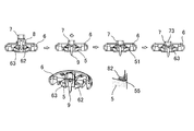
- FIG. 4 is a view showing a shoelace winding reel and an end portion of a shoelace embodying the present invention, wherein (a) is a perspective view, and (b) and (c) are sectional views.
- FIG. 5 is a view showing a shoelace winding device incorporating a shoelace winding reel embodying the present invention, in which (a) is a cross-sectional view showing a state in which the dial is in a locked position, and (b) It is sectional drawing which shows the state which has a dial in a cancellation
- FIG. 6 is a cross-sectional view showing a state in which a shaft member is assembled to a dial of a shoelace winding device incorporating a shoelace winding reel embodying the present invention.
- the present invention is a shoelace take-up reel stored in a reel storage portion of a base member fixed to a shoe and rotated by a dial,
- a shoelace winding drum comprising a large-diameter cylinder for winding a wire-like shoelace made of resin, metal or a composite thereof, and flange portions formed at both ends of the cylinder,
- a rotating shaft portion formed of a small-diameter cylindrical body disposed inside the shoelace winding drum;
- An annular portion connecting the inner peripheral surface of the shoelace winding drum and the outer peripheral surface of the rotating shaft portion;
- a shoe characterized in that a locking projection is provided in the groove for sandwiching and holding the tip of the shoelace introduced into the groove from the outer peripheral surface side of the shoelace winding drum.
- It is a string winding reel ”, and can be suitably embodied by the embodiment described below.
- FIG. 1 shows a shoe S equipped with a shoelace winding device 1 at a position corresponding to an ankle, and this shoe S fastens the upper part of the shoe S by a shoelace 2 made of a metal wire coated with a resin. Be able to.
- the shoelace winding device 1 includes a base member 3, a shoelace winding reel 4 for winding the shoelace 2, and a stopper member 5 for controlling the rotation and stop of the shoelace winding reel 4. And a dial 6 for rotationally driving the shoelace winding reel 4, and the dial 6 and the stopper member 5 are fixed to the base member 3 so as to be freely rotatable. And a spring member 8 whose one end is pivotally supported by the shaft member 7.
- the base member 3 can fix the shoelace winding device 1 to the shoe S by sewing and fixing a thin plate-like U-shaped flange 31 to the shoe S.
- a bottomed cylindrical reel storage portion 32 for rotatably storing the reel 4 is provided.
- the reel storage portion 32 has a rotation shaft 33 projecting from the center of the bottom portion for supporting the shoelace winding reel 4, and a gear 34 is formed on the inner peripheral surface thereof.
- the gear 34 forms a ratchet mechanism in cooperation with the claw 51 formed on the stopper member 5, and the cross section thereof is “saw saw” so that the claw 51 can move only in the direction of winding the shoelace 2 (forward rotation). It is formed in a “wave” shape.
- the base member 3 is formed with two shoelace pulling openings 35 opened at the bottom of the reel storage portion 32, and the shoelace 2 wound around the shoelace take-up reel 4 is connected to the reel storage portion. 32 can be pulled out to the outside.
- the shoelace winding reel 4 includes a shoelace winding drum 41 for winding the shoelace 2, a rotating shaft portion 42 disposed inside the shoelace winding drum 41, and the shoelace winding An annular groove 43 formed by the annular portion 43 connecting the inner peripheral surface of the drum 41 and the outer peripheral surface of the rotary shaft portion 42, the shoelace winding drum 41, the rotary shaft portion 42, and the annular portion 43. 44.
- the shoelace winding drum 41 is composed of a large-diameter cylindrical body 41a for winding the shoelace 2 and flange portions 41b formed at both ends of the cylindrical body 41a. It is comprised from the small diameter cylinder arrange
- the rotation shaft 33 of the base member 3 is inserted into the inner surface side of the rotation shaft portion 42, and the shoelace winding reel 4 is rotatable in the reel storage portion 32.
- the groove 44 of the reel 4 is disposed on the side facing the bottom of the base member 3 (hereinafter referred to as “lower side” for convenience of explanation, and the opposite side is referred to as “upper side”).
- a locking projection 45 is provided in the groove portion 44 for holding the tip portion of the shoelace 2 introduced into the groove portion 44 from the outer peripheral surface side of the drum 41 and holding it in the groove portion 44. .
- the locking projection 45 is an inner peripheral surface of the shoelace winding drum 41 and protrudes into the groove portion 44 from a position near the upper edge of the groove portion 44, and the shoelace 2 between the rotating shaft portion 42. And the shoelace 2 can be pressed and held on the bottom side (the annular portion 43 side) of the groove portion 44.
- the shoelace winding reel 4 has a slope 48 for guiding the distal end side of the shoelace 2 inserted through the wire insertion hole 47 outward in the axial direction (above the groove 44) of the shoelace winding drum 41. It is formed in the groove 44 along the inner peripheral surface.
- Each of the locking projections 45 is disposed at a position spaced apart by about 180 degrees in the groove portion 44, and the three wire insertion holes 47 are disposed therebetween, and the slope 48 includes the wire insertion hole. It is disposed at a position between the hole 47 and the locking projection 45.
- a plurality of fins 46 are formed on the upper side of the shoelace winding reel 4 along the inner peripheral surface of the shoelace winding drum 41, and the fins 52 formed on the lower side of the stopper member 5. , The rotation of the dial 6 can be transmitted to the shoelace winding reel 4.
- the stopper member 5 is fitted to the inner side (lower side) of the dial 6 by engaging mounting claws 53 projecting at the four corners thereof with engaging holes 61 formed through the dial 6. It is integrated with the dial 6 and is interposed between the reel 4 and the dial 6 so that the rotation of the dial 6 can be transmitted to the shoelace take-up reel 4, and the shoelace take-up reel 4 It is possible to realize a released state in which the shoelace take-up reel 4 is separated from the dial 6 so that can be freely rotated.
- the shaft member 7 is fixed to the base member 3 with a screw 9 so as to rotatably mount the integrated dial 6 and stopper member 5 to the base member 3. It is possible to hold and guide the dial 6 and the stopper member 5 in a movable state between a lock position where the dial 6 and the stopper member 5 are close to the base member 3 and a release position which is separated from the base member 3. ing.
- the shaft member 7 is formed in a quadrangular prism shape, and the spring member 8 is formed with respect to the bearing portion 71 formed by notching two opposing side portions of the shaft member in a direction orthogonal to the axial direction.
- the spring member 8 is pivotally supported so as to be rotatable. In other words, one spring member 8 is disposed at a position about 180 degrees apart from the shaft member 7.
- the shaft member 7 has a quadrangular prism shape, the strength of the bearing portion 71 can be increased and the shaft member 7 can be miniaturized. Further, the bearing portion 71 of the shaft member 7 is formed with the smallest inner diameter in the vicinity of the central portion in consideration of die cutting.
- the spring member 8 is entirely curved in a U-shape, and the curved spring portion 82 on the other end side contacts the locking portion 62 provided on the inner surface of the integrated dial 6 and stopper member 5. It comes to touch.
- the locking portion 62 with which the other end portion (spring portion 82) of the spring member 8 abuts is provided at the narrowest outer end portion of the spring housing space 63 formed in a wedge shape at the boundary portion between the dial 6 and the stopper member 5. It has been.
- the integrated dial 6 and stopper member 5 are moved from the locked position to the released position, so that the shoelace winding reel 4 can be switched from the locked state to the released state.
- a through hole 11 is formed in the center of the cap 10, and a shoelace winding reel is formed from the base member 3 by operating the screw 9 inside (lower side) of the cap 10 through the through hole 11. 4, the dial 6 and the shaft member 7 can be removed.
- nylon is processed with a swaging machine on a wire rope in which 49 strands of stainless steel with a diameter of 0.11 to 0.13 mm are twisted. What was coat
- covered with resin can be used suitably.
- the shoelace winding reel 4 is placed in the reel storage portion 32.
- Examples of the method for inserting the shoelace 2 through the wire insertion hole 47 include the method shown in FIG. 4B and the method shown in FIG. Whichever method is used, the tip of the shoelace 2 inserted through the wire insertion hole 47 is moved outwardly in the axial direction of the shoelace winding reel 4 by the slope 48, that is, outside the groove 44. Since it is guided, the operation
- the stopper member 5 is fitted to the inside (lower side) of the dial 6 so that the stopper member 5 is integrated with the dial 6 and the shaft member 7 and the spring member 8 are assembled to them.
- the spring member 8 is inserted into the substantially square shaft hole 64 formed in the dial 6 and the substantially square shaft hole 54 formed in the stopper member 5.
- the spring portion 82 of the spring member 8 is inserted into the spring accommodating space 63 from the expanded portion where the shaft hole 64 of the dial 6 is expanded, and the spring portion 82 is further narrowest from the inner end side of the spring accommodating space 63 to the outer end. It is guided so as to turn to the part side and is assembled to the dial 6. Since the flange 72 formed on the upper end portion of the shaft member 7 contacts the locking step portion 65 formed on the edge of the shaft hole 64 of the dial 6, the dial 6 does not come off the shaft member 7.
- the spring portion 82 of the spring member 8 is guided so as to rotate from the inner end side of the spring accommodating space 63 toward the outer end narrowest portion side, on the edge of the shaft hole 54 of the stopper member 5 (on the dial side). This is because the inclined surface 55 facing the) is formed.
- the shoelace winding device 1 can be assembled by fitting the cap 10 into the dial 6.
- a screwdriver is inserted from the through hole 11 of the cap 10 and the screw 9 is removed, so that the assembled stopper member 5, dial 6, shaft
- the member 7 and the spring member 8 can be removed from the base member 3.
- the stopper member 5, the dial 6, the shaft member 7, and the spring member 8 are used. It can be removed from the base member 3 while being assembled, which is very effective in improving the efficiency of maintenance or repair work.
- each member in the shoelace winding device 1 of the present embodiment the following materials are used as an example in consideration of strength, durability, elasticity, and the like, but are limited to these materials. It is not something.
- Base member 3 Nylon Shoelace winding reel 4, Stopper member 5, Shaft member 7 ... POM (Polyacetal) Dial 6 ... Nylon and TPE (thermoplastic elastomer) around it Spring member 8 ... Stainless steel Screw 9 ... Carbon steel Cap 10 ... ABS resin
- a method of using the shoelace winding device 1 configured as described above will be described.
- the dial 6 of the shoelace winding device 1 is rotated at the locked position where the dial 6 is brought close to the base member 3, and the shoelace 2 is attached to the shoelace. It is wound around the take-up reel 4.
- the claw 51 of the stopper member 5 abuts on the gear 34, so that the shoelace winding reel 4 does not rotate in the direction in which the shoelace 2 is loosened.
- the spring member 8 is shown on the left side of FIG. 5 when the dial 6 is in the lock position.
- the dial 6 is held in the locked position.
- the spring member 8 faces the direction of lifting the shaft member 7 and pressing the dial 6 downward.
- the dial 6 of the shoelace winding device 1 is pulled upward.
- the spring member 8 is compressed, and by pulling the dial 6 further upward against the repulsive force, the spring member 8 exceeds the reversal position where the spring member 8 is compressed most, and between the lock position and the release position.
- the direction in which the spring member 8 is compressed is switched to move the dial 6 to the release position away from the base member 3 (the state shown on the right side of FIG. 5).
- the spring member 8 faces the direction in which the shaft member 7 is pressed down and the dial 6 is lifted up.
- the other end portion (spring portion 82) of the spring member 8 is always in contact with a locking portion 64 provided on the inner surface of the dial 6, and wear of parts can be prevented.
- the “dial” is not particularly limited as long as it functions as an operation unit for rotationally driving the shoelace winding reel 4, and has a polygonal shape. It may be.
- the present invention is not limited to the shoelace winding reel for the shoelace winding device 1 for fastening the wired shoelace 2 as in the illustrated example, and the shoelace 2 for fastening different portions of the shoe S.
- the present invention may be embodied as being incorporated in a shoelace winding device for tightening.
- the material, shape, dimensions, angle, installation position, size, number, etc. of each part of the shoelace winding device and the shoelace winding reel are appropriately changed without departing from the spirit of the present invention.
- the locking protrusion 45 may be provided so as to protrude into the groove 44 from the rotating shaft portion 42 side, or the slope 48 may be provided along the outer peripheral surface of the rotating shaft portion 42.
- the present invention is suitable as a shoelace take-up reel built in a shoelace take-up device that is compact and lightweight, has excellent durability and assembly workability, and can be easily used for a wide variety of shoes. Is available.
Landscapes
- Footwear And Its Accessory, Manufacturing Method And Apparatuses (AREA)
Priority Applications (7)
| Application Number | Priority Date | Filing Date | Title |
|---|---|---|---|
| EP13886147.1A EP2845505A4 (en) | 2013-06-18 | 2013-10-17 | SCHNÜRRIEMENWICKELROLLE |
| HK15104395.6A HK1203783B (en) | 2013-06-18 | 2013-10-17 | Shoelace winding reel |
| CN201380027473.4A CN104470394B (zh) | 2013-06-18 | 2013-10-17 | 鞋带卷取用卷盘 |
| CA2876003A CA2876003C (en) | 2013-06-18 | 2013-10-17 | Shoelace winding reel |
| US14/405,738 US9717305B2 (en) | 2013-06-18 | 2013-10-17 | Shoelace winding reel |
| KR1020147021605A KR101706691B1 (ko) | 2013-06-18 | 2013-10-17 | 신발끈 권취용 릴 |
| AU2013391430A AU2013391430B2 (en) | 2013-06-18 | 2013-10-17 | Shoelace winding reel |
Applications Claiming Priority (2)
| Application Number | Priority Date | Filing Date | Title |
|---|---|---|---|
| JP2013-127612 | 2013-06-18 | ||
| JP2013127612A JP6105404B2 (ja) | 2013-06-18 | 2013-06-18 | 靴紐巻取用リール |
Publications (1)
| Publication Number | Publication Date |
|---|---|
| WO2014203416A1 true WO2014203416A1 (ja) | 2014-12-24 |
Family
ID=52104175
Family Applications (1)
| Application Number | Title | Priority Date | Filing Date |
|---|---|---|---|
| PCT/JP2013/078117 WO2014203416A1 (ja) | 2013-06-18 | 2013-10-17 | 靴紐巻取用リール |
Country Status (9)
Cited By (4)
| Publication number | Priority date | Publication date | Assignee | Title |
|---|---|---|---|---|
| CN105256321A (zh) * | 2015-10-30 | 2016-01-20 | 湖南金化科技集团有限公司 | 一种钢铁制件表面处理剂及其制备方法 |
| JP2019000213A (ja) * | 2017-06-13 | 2019-01-10 | キャラウェイ・ゴルフ・カンパニ | 靴 |
| US10368608B2 (en) | 2016-07-22 | 2019-08-06 | Nike, Inc. | Dynamic lacing system |
| US11129447B2 (en) | 2018-09-06 | 2021-09-28 | Nike, Inc. | Dynamic lacing system with feedback mechanism |
Families Citing this family (38)
| Publication number | Priority date | Publication date | Assignee | Title |
|---|---|---|---|---|
| KR101865201B1 (ko) * | 2013-09-13 | 2018-06-08 | 보아 테크놀러지, 인크. | 파손 보상 레이스 인장 장치 및 방법 |
| JP6406919B2 (ja) | 2014-08-11 | 2018-10-17 | 株式会社ジャパーナ | 靴紐巻取装置の取付構造 |
| US10264852B2 (en) * | 2015-01-14 | 2019-04-23 | Sug Whan Kim | String winding and unwinding apparatus |
| KR101782151B1 (ko) * | 2015-06-12 | 2017-10-13 | 김석환 | 끈 조임장치 |
| KR101768182B1 (ko) | 2015-06-26 | 2017-08-30 | 신병민 | 신발끈 자동 조임 장치 |
| KR101821296B1 (ko) * | 2015-08-17 | 2018-01-25 | 주식회사 박의지 | 와이어 결속 장치 |
| US10390589B2 (en) * | 2016-03-15 | 2019-08-27 | Nike, Inc. | Drive mechanism for automated footwear platform |
| US9861164B2 (en) * | 2016-03-15 | 2018-01-09 | Nike, Inc. | Tensioning system and reel member for an article of footwear |
| US9961963B2 (en) * | 2016-03-15 | 2018-05-08 | Nike, Inc. | Lacing engine for automated footwear platform |
| US10342293B2 (en) * | 2016-03-15 | 2019-07-09 | Nike, Inc. | Method of forming an aperture in a reel member of a tensioning system for an article of footwear |
| JP6882827B2 (ja) | 2016-08-10 | 2021-06-02 | 株式会社アルペン | 巻取装置 |
| KR20180062475A (ko) | 2016-11-30 | 2018-06-11 | 김진호 | 릴시스템의 와이어 묶는방법 |
| KR101837194B1 (ko) * | 2016-12-30 | 2018-03-13 | 소윤서 | 줄 길이 조절장치 |
| CN106723663B (zh) * | 2017-01-24 | 2019-05-24 | 深圳市悠宁科技有限公司 | 鞋带收放装置 |
| JP6881993B2 (ja) * | 2017-02-01 | 2021-06-02 | 株式会社アルペン | 紐巻取装置を備えた物品 |
| KR102043253B1 (ko) | 2017-02-22 | 2019-11-11 | 김석환 | 끈조절장치 |
| DE102018201019A1 (de) * | 2017-02-28 | 2018-08-30 | Fidlock Gmbh | Verschlussvorrichtung mit einem Wickelelement |
| CN107232690A (zh) * | 2017-07-26 | 2017-10-10 | 莆田市城厢区旋乐美鞋材有限公司 | 一种鞋带旋紧装置 |
| KR101998160B1 (ko) | 2018-02-09 | 2019-07-09 | 신윤익 | 신발끈 조임 장치 |
| US10834998B2 (en) * | 2018-04-13 | 2020-11-17 | Wolverine Outdoors, Inc. | Footwear including a holding cage |
| CN110495666B (zh) * | 2018-05-16 | 2022-01-25 | 渥弗林户外用品公司 | 包括保持架的鞋类 |
| CN112822954B (zh) | 2018-08-31 | 2022-12-13 | 耐克创新有限合伙公司 | 具有带凹口的线轴的自动系带鞋类马达 |
| CN111003616A (zh) * | 2018-10-08 | 2020-04-14 | 王祐谦 | 卷线器 |
| KR102224456B1 (ko) * | 2019-05-02 | 2021-03-08 | 주식회사 신경 | 와이어 권취 조절장치 |
| US12091281B2 (en) * | 2019-06-14 | 2024-09-17 | Shinkyung Inc | Wire winding adjusting device and wire reel |
| KR102208341B1 (ko) * | 2019-06-14 | 2021-01-27 | 주식회사 신경 | 와이어 권취 조절장치 |
| KR102368924B1 (ko) | 2020-02-28 | 2022-03-03 | 김진호 | 끈 조임장치 |
| IT202000029228A1 (it) * | 2020-12-01 | 2022-06-01 | 10 Ottobre S R L | Dispositivo di chiusura a rotore |
| WO2022221312A1 (en) * | 2021-04-15 | 2022-10-20 | Pride Manufacturing Company, Llc | Systems and methods for a dial cover for a rotary closure for a shoe |
| JP2023013847A (ja) * | 2021-07-16 | 2023-01-26 | 株式会社シマノ | 靴 |
| JP3247224U (ja) | 2021-08-06 | 2024-06-27 | 栄興 劉 | 紐締め器 |
| US12295894B2 (en) | 2021-11-09 | 2025-05-13 | Allen Medical Systems, Inc. | Surgical traction boot having resilient heel pad and medial and lateral straps |
| TWI813454B (zh) * | 2022-09-23 | 2023-08-21 | 王祐謙 | 捲線器 |
| CN115744503A (zh) * | 2022-11-21 | 2023-03-07 | 江馨月 | 一种正反转松紧系绳装置 |
| JP7538990B2 (ja) * | 2022-12-15 | 2024-08-23 | 深▲せん▼市愛康偉達智能医療科技有限公司 | スプール、スプールを含む締付装置、及び、スプールと紐との結合方法 |
| TWI857853B (zh) * | 2023-09-23 | 2024-10-01 | 陳金柱 | 繫線耦合結構、繫線耦合結構安裝方法及繫線耦合結構安裝治具 |
| CN120379917A (zh) * | 2024-02-01 | 2025-07-25 | 深圳市爱旋科技有限公司 | 可微调绳线收放装置及物品 |
| KR102719748B1 (ko) * | 2024-02-28 | 2024-10-18 | 박인웅 | 발목염좌용 보호구 |
Citations (4)
| Publication number | Priority date | Publication date | Assignee | Title |
|---|---|---|---|---|
| WO1999009850A1 (en) * | 1997-08-22 | 1999-03-04 | Hammerslag Gary R | Footwear lacing system |
| JP2010148927A (ja) | 1999-09-02 | 2010-07-08 | Boa Technology Inc | 履物の紐掛けシステム |
| JP4538836B2 (ja) | 2003-08-04 | 2010-09-08 | 株式会社ジャパーナ | ケーブル式靴における引張りケーブル、特に複数本の引張りケーブル束の装着装置 |
| WO2011137405A2 (en) * | 2010-04-30 | 2011-11-03 | Boa Technology, Inc. | Reel based lacing system |
Family Cites Families (34)
| Publication number | Priority date | Publication date | Assignee | Title |
|---|---|---|---|---|
| JPS583428Y2 (ja) | 1978-01-17 | 1983-01-20 | 東成産業株式会社 | 物干し用ハンガ−ロ−プ |
| IT1193578B (it) * | 1981-01-28 | 1988-07-08 | Nordica Spa | Dispositivo di chiusura particolarmente per scarponi da sci |
| DE3926514A1 (de) | 1989-08-10 | 1991-02-14 | Weinmann & Co Kg | Drehverschluss fuer einen sportschuh, insbesondere einen skischuh |
| JPH04171774A (ja) | 1990-11-02 | 1992-06-18 | Tokuji Sawara | 太陽電池装置 |
| US5157813A (en) * | 1991-10-31 | 1992-10-27 | William Carroll | Shoelace tensioning device |
| JPH07208A (ja) * | 1991-12-20 | 1995-01-06 | Kobatsuku:Kk | 靴紐締付具 |
| DE9200982U1 (de) * | 1992-01-28 | 1993-05-27 | PUMA AG Rudolf Dassler Sport, 8522 Herzogenaurach | Schuh mit einem Zentralverschluß |
| DE4240916C1 (de) | 1992-12-04 | 1993-10-07 | Jungkind Roland | Schuhverschluß |
| EP0651954B1 (de) | 1993-11-04 | 1999-02-10 | Am S.R.L. | Spannvorrichtung für einen Sportschuh |
| US20060156517A1 (en) | 1997-08-22 | 2006-07-20 | Hammerslag Gary R | Reel based closure system |
| WO2002024543A1 (en) * | 2000-09-19 | 2002-03-28 | Freed Anna B | Closure |
| US20110167543A1 (en) * | 2004-05-07 | 2011-07-14 | Enventys, Llc | Adjustable protective apparel |
| US7516914B2 (en) | 2004-05-07 | 2009-04-14 | Enventys, Llc | Bi-directional device |
| CN101193568B (zh) * | 2004-10-29 | 2011-11-30 | 博技术有限公司 | 基于卷轴的闭合系统及使用该系统的鞋类物品 |
| KR100598627B1 (ko) * | 2005-06-27 | 2006-07-13 | 주식회사 신경 | 신발끈 조임기 |
| DE102005037967A1 (de) | 2005-08-11 | 2007-02-15 | Head Germany Gmbh | Drehverschluss für einen Schuh |
| WO2007081822A2 (en) * | 2006-01-06 | 2007-07-19 | Boa Technology, Inc. | Rough and fine adjustment closure system |
| KR20100129278A (ko) * | 2008-01-18 | 2010-12-08 | 보아 테크놀러지, 인크. | 클로저 시스템 |
| KR101688997B1 (ko) | 2008-11-21 | 2016-12-22 | 보아 테크놀러지, 인크. | 릴 기반 끈 조임 시스템 |
| US8245371B2 (en) * | 2009-04-01 | 2012-08-21 | Chin Chu Chen | String securing device |
| TW201127310A (en) * | 2010-02-11 | 2011-08-16 | jin-zhu Chen | Step-less finetuning buckle |
| US8707486B2 (en) | 2010-02-16 | 2014-04-29 | Allen Medical Systems, Inc. | Lacing system to secure a limb in a surgical support apparatus |
| US9375053B2 (en) * | 2012-03-15 | 2016-06-28 | Boa Technology, Inc. | Tightening mechanisms and applications including the same |
| AU2011272791B2 (en) * | 2010-07-01 | 2014-05-29 | 3M Innovative Properties Company | Braces using lacing systems |
| JP5727771B2 (ja) | 2010-12-08 | 2015-06-03 | 株式会社ジャパーナ | 靴ひもの巻取装置 |
| US8353087B2 (en) | 2011-03-07 | 2013-01-15 | Chin-Chu Chen | Closure device |
| KR101107372B1 (ko) | 2011-05-30 | 2012-01-19 | 소윤서 | 줄 길이 조절장치 |
| KR101099458B1 (ko) * | 2011-07-25 | 2011-12-27 | 주식회사 신경 | 신발끈 조임장치 |
| US9101181B2 (en) | 2011-10-13 | 2015-08-11 | Boa Technology Inc. | Reel-based lacing system |
| WO2014082652A1 (de) * | 2012-11-30 | 2014-06-05 | Puma SE | Drehverschluss für einen schuh |
| EP3607845B1 (en) | 2013-01-28 | 2022-11-09 | Boa Technology Inc. | Lace fixation assembly and system |
| KR101506676B1 (ko) * | 2013-09-03 | 2015-03-30 | 주식회사 신경 | 와이어 조임장치 및 그의 장착방법 |
| TWI561453B (en) * | 2014-02-17 | 2016-12-11 | Chin Chu Chen | A device for tightening and loosening a lace |
| US9364054B2 (en) | 2014-04-09 | 2016-06-14 | Tristan S. Gittens | Accessory cinching device |
-
2013
- 2013-06-18 JP JP2013127612A patent/JP6105404B2/ja active Active
- 2013-10-17 AU AU2013391430A patent/AU2013391430B2/en not_active Ceased
- 2013-10-17 EP EP13886147.1A patent/EP2845505A4/en not_active Withdrawn
- 2013-10-17 CA CA2876003A patent/CA2876003C/en not_active Expired - Fee Related
- 2013-10-17 CN CN201380027473.4A patent/CN104470394B/zh active Active
- 2013-10-17 US US14/405,738 patent/US9717305B2/en active Active
- 2013-10-17 WO PCT/JP2013/078117 patent/WO2014203416A1/ja active Application Filing
- 2013-10-17 KR KR1020147021605A patent/KR101706691B1/ko not_active Expired - Fee Related
-
2014
- 2014-06-04 TW TW103119314A patent/TWI577301B/zh not_active IP Right Cessation
Patent Citations (5)
| Publication number | Priority date | Publication date | Assignee | Title |
|---|---|---|---|---|
| WO1999009850A1 (en) * | 1997-08-22 | 1999-03-04 | Hammerslag Gary R | Footwear lacing system |
| JP4171774B2 (ja) | 1997-08-22 | 2008-10-29 | ボア テクノロジー、インク. | 履物用ひも締めシステム |
| JP2010148927A (ja) | 1999-09-02 | 2010-07-08 | Boa Technology Inc | 履物の紐掛けシステム |
| JP4538836B2 (ja) | 2003-08-04 | 2010-09-08 | 株式会社ジャパーナ | ケーブル式靴における引張りケーブル、特に複数本の引張りケーブル束の装着装置 |
| WO2011137405A2 (en) * | 2010-04-30 | 2011-11-03 | Boa Technology, Inc. | Reel based lacing system |
Non-Patent Citations (1)
| Title |
|---|
| See also references of EP2845505A4 * |
Cited By (15)
| Publication number | Priority date | Publication date | Assignee | Title |
|---|---|---|---|---|
| CN105256321A (zh) * | 2015-10-30 | 2016-01-20 | 湖南金化科技集团有限公司 | 一种钢铁制件表面处理剂及其制备方法 |
| US11026472B2 (en) | 2016-07-22 | 2021-06-08 | Nike, Inc. | Dynamic lacing system |
| US11730229B2 (en) | 2016-07-22 | 2023-08-22 | Nike, Inc. | Dynamic lacing system |
| US10368607B2 (en) | 2016-07-22 | 2019-08-06 | Nike, Inc. | Dynamic lacing system |
| US10463102B2 (en) | 2016-07-22 | 2019-11-05 | Nike, Inc. | Dynamic lacing system |
| US10477912B2 (en) * | 2016-07-22 | 2019-11-19 | Nike, Inc. | Dynamic lacing system |
| US11058167B2 (en) | 2016-07-22 | 2021-07-13 | Nike, Inc. | Dynamic lacing system |
| US10368608B2 (en) | 2016-07-22 | 2019-08-06 | Nike, Inc. | Dynamic lacing system |
| US11160325B2 (en) * | 2016-07-22 | 2021-11-02 | Nike, Inc. | Dynamic lacing system |
| US11490675B2 (en) | 2016-07-22 | 2022-11-08 | Nike, Inc. | Dynamic lacing system |
| US11882901B2 (en) | 2016-07-22 | 2024-01-30 | Nike, Inc. | Dynamic lacing system |
| JP2019000213A (ja) * | 2017-06-13 | 2019-01-10 | キャラウェイ・ゴルフ・カンパニ | 靴 |
| US11129447B2 (en) | 2018-09-06 | 2021-09-28 | Nike, Inc. | Dynamic lacing system with feedback mechanism |
| US11678723B2 (en) | 2018-09-06 | 2023-06-20 | Nike, Inc. | Dynamic lacing system with feedback mechanism |
| US12121109B2 (en) | 2018-09-06 | 2024-10-22 | Nike, Inc. | Dynamic lacing system with feedback mechanism |
Also Published As
| Publication number | Publication date |
|---|---|
| CA2876003C (en) | 2016-12-20 |
| TW201509326A (zh) | 2015-03-16 |
| TWI577301B (zh) | 2017-04-11 |
| CN104470394B (zh) | 2016-05-25 |
| EP2845505A4 (en) | 2016-05-25 |
| EP2845505A1 (en) | 2015-03-11 |
| KR101706691B1 (ko) | 2017-02-14 |
| HK1203783A1 (zh) | 2015-11-06 |
| US20160262497A1 (en) | 2016-09-15 |
| CA2876003A1 (en) | 2014-12-24 |
| AU2013391430A8 (en) | 2015-01-29 |
| JP2015000297A (ja) | 2015-01-05 |
| KR20150032516A (ko) | 2015-03-26 |
| AU2013391430B2 (en) | 2016-10-27 |
| AU2013391430A1 (en) | 2015-01-22 |
| US9717305B2 (en) | 2017-08-01 |
| JP6105404B2 (ja) | 2017-03-29 |
| CN104470394A (zh) | 2015-03-25 |
Similar Documents
| Publication | Publication Date | Title |
|---|---|---|
| JP6105404B2 (ja) | 靴紐巻取用リール | |
| JP6087219B2 (ja) | 靴紐巻取装置 | |
| CN111115389B (zh) | 紧固装置 | |
| JP4473301B2 (ja) | チェーン伝動用テンショナレバー | |
| WO2018030108A1 (ja) | 巻取装置 | |
| WO2017175586A1 (ja) | 巻取装置 | |
| CN114291666B (zh) | 一种收放线装置 | |
| WO2017068937A1 (ja) | 巻取装置 | |
| HK1203783B (en) | Shoelace winding reel | |
| HK1203782B (en) | Shoelace winding device | |
| HK40007060B (zh) | 具备绳卷取装置的物品 | |
| HK1231337B (zh) | 鞋带卷取装置 |
Legal Events
| Date | Code | Title | Description |
|---|---|---|---|
| ENP | Entry into the national phase |
Ref document number: 20147021605 Country of ref document: KR Kind code of ref document: A |
|
| ENP | Entry into the national phase |
Ref document number: 2876003 Country of ref document: CA |
|
| WWE | Wipo information: entry into national phase |
Ref document number: 14405738 Country of ref document: US Ref document number: 2013886147 Country of ref document: EP Ref document number: 2013391430 Country of ref document: AU |
|
| 121 | Ep: the epo has been informed by wipo that ep was designated in this application |
Ref document number: 13886147 Country of ref document: EP Kind code of ref document: A1 |
|
| NENP | Non-entry into the national phase |
Ref country code: DE |