WO2014203406A1 - 排ガス処理装置、ディーゼルエンジン及び排ガス処理方法 - Google Patents
排ガス処理装置、ディーゼルエンジン及び排ガス処理方法 Download PDFInfo
- Publication number
- WO2014203406A1 WO2014203406A1 PCT/JP2013/069556 JP2013069556W WO2014203406A1 WO 2014203406 A1 WO2014203406 A1 WO 2014203406A1 JP 2013069556 W JP2013069556 W JP 2013069556W WO 2014203406 A1 WO2014203406 A1 WO 2014203406A1
- Authority
- WO
- WIPO (PCT)
- Prior art keywords
- exhaust gas
- flow rate
- pressure
- catalyst
- diesel engine
- Prior art date
- Legal status (The legal status is an assumption and is not a legal conclusion. Google has not performed a legal analysis and makes no representation as to the accuracy of the status listed.)
- Ceased
Links
Images



Classifications
-
- F—MECHANICAL ENGINEERING; LIGHTING; HEATING; WEAPONS; BLASTING
- F01—MACHINES OR ENGINES IN GENERAL; ENGINE PLANTS IN GENERAL; STEAM ENGINES
- F01N—GAS-FLOW SILENCERS OR EXHAUST APPARATUS FOR MACHINES OR ENGINES IN GENERAL; GAS-FLOW SILENCERS OR EXHAUST APPARATUS FOR INTERNAL-COMBUSTION ENGINES
- F01N3/00—Exhaust or silencing apparatus having means for purifying, rendering innocuous, or otherwise treating exhaust
- F01N3/08—Exhaust or silencing apparatus having means for purifying, rendering innocuous, or otherwise treating exhaust for rendering innocuous
- F01N3/10—Exhaust or silencing apparatus having means for purifying, rendering innocuous, or otherwise treating exhaust for rendering innocuous by thermal or catalytic conversion of noxious components of exhaust
- F01N3/18—Exhaust or silencing apparatus having means for purifying, rendering innocuous, or otherwise treating exhaust for rendering innocuous by thermal or catalytic conversion of noxious components of exhaust characterised by methods of operation; Control
- F01N3/20—Exhaust or silencing apparatus having means for purifying, rendering innocuous, or otherwise treating exhaust for rendering innocuous by thermal or catalytic conversion of noxious components of exhaust characterised by methods of operation; Control specially adapted for catalytic conversion
- F01N3/206—Adding periodically or continuously substances to exhaust gases for promoting purification, e.g. catalytic material in liquid form, NOx reducing agents
- F01N3/208—Control of selective catalytic reduction [SCR], e.g. by adjusting the dosing of reducing agent
-
- F—MECHANICAL ENGINEERING; LIGHTING; HEATING; WEAPONS; BLASTING
- F01—MACHINES OR ENGINES IN GENERAL; ENGINE PLANTS IN GENERAL; STEAM ENGINES
- F01N—GAS-FLOW SILENCERS OR EXHAUST APPARATUS FOR MACHINES OR ENGINES IN GENERAL; GAS-FLOW SILENCERS OR EXHAUST APPARATUS FOR INTERNAL-COMBUSTION ENGINES
- F01N3/00—Exhaust or silencing apparatus having means for purifying, rendering innocuous, or otherwise treating exhaust
- F01N3/08—Exhaust or silencing apparatus having means for purifying, rendering innocuous, or otherwise treating exhaust for rendering innocuous
- F01N3/0807—Exhaust or silencing apparatus having means for purifying, rendering innocuous, or otherwise treating exhaust for rendering innocuous by using absorbents or adsorbents
- F01N3/0821—Exhaust or silencing apparatus having means for purifying, rendering innocuous, or otherwise treating exhaust for rendering innocuous by using absorbents or adsorbents combined with particulate filter
-
- F—MECHANICAL ENGINEERING; LIGHTING; HEATING; WEAPONS; BLASTING
- F01—MACHINES OR ENGINES IN GENERAL; ENGINE PLANTS IN GENERAL; STEAM ENGINES
- F01N—GAS-FLOW SILENCERS OR EXHAUST APPARATUS FOR MACHINES OR ENGINES IN GENERAL; GAS-FLOW SILENCERS OR EXHAUST APPARATUS FOR INTERNAL-COMBUSTION ENGINES
- F01N13/00—Exhaust or silencing apparatus characterised by constructional features
- F01N13/009—Exhaust or silencing apparatus characterised by constructional features having two or more separate purifying devices arranged in series
-
- F—MECHANICAL ENGINEERING; LIGHTING; HEATING; WEAPONS; BLASTING
- F01—MACHINES OR ENGINES IN GENERAL; ENGINE PLANTS IN GENERAL; STEAM ENGINES
- F01N—GAS-FLOW SILENCERS OR EXHAUST APPARATUS FOR MACHINES OR ENGINES IN GENERAL; GAS-FLOW SILENCERS OR EXHAUST APPARATUS FOR INTERNAL-COMBUSTION ENGINES
- F01N13/00—Exhaust or silencing apparatus characterised by constructional features
- F01N13/011—Exhaust or silencing apparatus characterised by constructional features having two or more purifying devices arranged in parallel
-
- F—MECHANICAL ENGINEERING; LIGHTING; HEATING; WEAPONS; BLASTING
- F01—MACHINES OR ENGINES IN GENERAL; ENGINE PLANTS IN GENERAL; STEAM ENGINES
- F01N—GAS-FLOW SILENCERS OR EXHAUST APPARATUS FOR MACHINES OR ENGINES IN GENERAL; GAS-FLOW SILENCERS OR EXHAUST APPARATUS FOR INTERNAL-COMBUSTION ENGINES
- F01N3/00—Exhaust or silencing apparatus having means for purifying, rendering innocuous, or otherwise treating exhaust
- F01N3/08—Exhaust or silencing apparatus having means for purifying, rendering innocuous, or otherwise treating exhaust for rendering innocuous
- F01N3/0807—Exhaust or silencing apparatus having means for purifying, rendering innocuous, or otherwise treating exhaust for rendering innocuous by using absorbents or adsorbents
- F01N3/0828—Exhaust or silencing apparatus having means for purifying, rendering innocuous, or otherwise treating exhaust for rendering innocuous by using absorbents or adsorbents characterised by the absorbed or adsorbed substances
- F01N3/0842—Nitrogen oxides
-
- F—MECHANICAL ENGINEERING; LIGHTING; HEATING; WEAPONS; BLASTING
- F01—MACHINES OR ENGINES IN GENERAL; ENGINE PLANTS IN GENERAL; STEAM ENGINES
- F01N—GAS-FLOW SILENCERS OR EXHAUST APPARATUS FOR MACHINES OR ENGINES IN GENERAL; GAS-FLOW SILENCERS OR EXHAUST APPARATUS FOR INTERNAL-COMBUSTION ENGINES
- F01N9/00—Electrical control of exhaust gas treating apparatus
- F01N9/002—Electrical control of exhaust gas treating apparatus of filter regeneration
-
- F—MECHANICAL ENGINEERING; LIGHTING; HEATING; WEAPONS; BLASTING
- F01—MACHINES OR ENGINES IN GENERAL; ENGINE PLANTS IN GENERAL; STEAM ENGINES
- F01N—GAS-FLOW SILENCERS OR EXHAUST APPARATUS FOR MACHINES OR ENGINES IN GENERAL; GAS-FLOW SILENCERS OR EXHAUST APPARATUS FOR INTERNAL-COMBUSTION ENGINES
- F01N2560/00—Exhaust systems with means for detecting or measuring exhaust gas components or characteristics
- F01N2560/02—Exhaust systems with means for detecting or measuring exhaust gas components or characteristics the means being an exhaust gas sensor
- F01N2560/026—Exhaust systems with means for detecting or measuring exhaust gas components or characteristics the means being an exhaust gas sensor for measuring or detecting NOx
-
- F—MECHANICAL ENGINEERING; LIGHTING; HEATING; WEAPONS; BLASTING
- F01—MACHINES OR ENGINES IN GENERAL; ENGINE PLANTS IN GENERAL; STEAM ENGINES
- F01N—GAS-FLOW SILENCERS OR EXHAUST APPARATUS FOR MACHINES OR ENGINES IN GENERAL; GAS-FLOW SILENCERS OR EXHAUST APPARATUS FOR INTERNAL-COMBUSTION ENGINES
- F01N2560/00—Exhaust systems with means for detecting or measuring exhaust gas components or characteristics
- F01N2560/06—Exhaust systems with means for detecting or measuring exhaust gas components or characteristics the means being a temperature sensor
-
- F—MECHANICAL ENGINEERING; LIGHTING; HEATING; WEAPONS; BLASTING
- F01—MACHINES OR ENGINES IN GENERAL; ENGINE PLANTS IN GENERAL; STEAM ENGINES
- F01N—GAS-FLOW SILENCERS OR EXHAUST APPARATUS FOR MACHINES OR ENGINES IN GENERAL; GAS-FLOW SILENCERS OR EXHAUST APPARATUS FOR INTERNAL-COMBUSTION ENGINES
- F01N2560/00—Exhaust systems with means for detecting or measuring exhaust gas components or characteristics
- F01N2560/08—Exhaust systems with means for detecting or measuring exhaust gas components or characteristics the means being a pressure sensor
-
- F—MECHANICAL ENGINEERING; LIGHTING; HEATING; WEAPONS; BLASTING
- F01—MACHINES OR ENGINES IN GENERAL; ENGINE PLANTS IN GENERAL; STEAM ENGINES
- F01N—GAS-FLOW SILENCERS OR EXHAUST APPARATUS FOR MACHINES OR ENGINES IN GENERAL; GAS-FLOW SILENCERS OR EXHAUST APPARATUS FOR INTERNAL-COMBUSTION ENGINES
- F01N2560/00—Exhaust systems with means for detecting or measuring exhaust gas components or characteristics
- F01N2560/14—Exhaust systems with means for detecting or measuring exhaust gas components or characteristics having more than one sensor of one kind
-
- F—MECHANICAL ENGINEERING; LIGHTING; HEATING; WEAPONS; BLASTING
- F01—MACHINES OR ENGINES IN GENERAL; ENGINE PLANTS IN GENERAL; STEAM ENGINES
- F01N—GAS-FLOW SILENCERS OR EXHAUST APPARATUS FOR MACHINES OR ENGINES IN GENERAL; GAS-FLOW SILENCERS OR EXHAUST APPARATUS FOR INTERNAL-COMBUSTION ENGINES
- F01N2570/00—Exhaust treating apparatus eliminating, absorbing or adsorbing specific elements or compounds
- F01N2570/14—Nitrogen oxides
-
- F—MECHANICAL ENGINEERING; LIGHTING; HEATING; WEAPONS; BLASTING
- F01—MACHINES OR ENGINES IN GENERAL; ENGINE PLANTS IN GENERAL; STEAM ENGINES
- F01N—GAS-FLOW SILENCERS OR EXHAUST APPARATUS FOR MACHINES OR ENGINES IN GENERAL; GAS-FLOW SILENCERS OR EXHAUST APPARATUS FOR INTERNAL-COMBUSTION ENGINES
- F01N2610/00—Adding substances to exhaust gases
- F01N2610/02—Adding substances to exhaust gases the substance being ammonia or urea
-
- F—MECHANICAL ENGINEERING; LIGHTING; HEATING; WEAPONS; BLASTING
- F01—MACHINES OR ENGINES IN GENERAL; ENGINE PLANTS IN GENERAL; STEAM ENGINES
- F01N—GAS-FLOW SILENCERS OR EXHAUST APPARATUS FOR MACHINES OR ENGINES IN GENERAL; GAS-FLOW SILENCERS OR EXHAUST APPARATUS FOR INTERNAL-COMBUSTION ENGINES
- F01N2610/00—Adding substances to exhaust gases
- F01N2610/14—Arrangements for the supply of substances, e.g. conduits
-
- F—MECHANICAL ENGINEERING; LIGHTING; HEATING; WEAPONS; BLASTING
- F01—MACHINES OR ENGINES IN GENERAL; ENGINE PLANTS IN GENERAL; STEAM ENGINES
- F01N—GAS-FLOW SILENCERS OR EXHAUST APPARATUS FOR MACHINES OR ENGINES IN GENERAL; GAS-FLOW SILENCERS OR EXHAUST APPARATUS FOR INTERNAL-COMBUSTION ENGINES
- F01N2900/00—Details of electrical control or of the monitoring of the exhaust gas treating apparatus
- F01N2900/04—Methods of control or diagnosing
- F01N2900/0416—Methods of control or diagnosing using the state of a sensor, e.g. of an exhaust gas sensor
-
- F—MECHANICAL ENGINEERING; LIGHTING; HEATING; WEAPONS; BLASTING
- F01—MACHINES OR ENGINES IN GENERAL; ENGINE PLANTS IN GENERAL; STEAM ENGINES
- F01N—GAS-FLOW SILENCERS OR EXHAUST APPARATUS FOR MACHINES OR ENGINES IN GENERAL; GAS-FLOW SILENCERS OR EXHAUST APPARATUS FOR INTERNAL-COMBUSTION ENGINES
- F01N2900/00—Details of electrical control or of the monitoring of the exhaust gas treating apparatus
- F01N2900/06—Parameters used for exhaust control or diagnosing
- F01N2900/0601—Parameters used for exhaust control or diagnosing being estimated
-
- F—MECHANICAL ENGINEERING; LIGHTING; HEATING; WEAPONS; BLASTING
- F01—MACHINES OR ENGINES IN GENERAL; ENGINE PLANTS IN GENERAL; STEAM ENGINES
- F01N—GAS-FLOW SILENCERS OR EXHAUST APPARATUS FOR MACHINES OR ENGINES IN GENERAL; GAS-FLOW SILENCERS OR EXHAUST APPARATUS FOR INTERNAL-COMBUSTION ENGINES
- F01N2900/00—Details of electrical control or of the monitoring of the exhaust gas treating apparatus
- F01N2900/06—Parameters used for exhaust control or diagnosing
- F01N2900/08—Parameters used for exhaust control or diagnosing said parameters being related to the engine
-
- F—MECHANICAL ENGINEERING; LIGHTING; HEATING; WEAPONS; BLASTING
- F01—MACHINES OR ENGINES IN GENERAL; ENGINE PLANTS IN GENERAL; STEAM ENGINES
- F01N—GAS-FLOW SILENCERS OR EXHAUST APPARATUS FOR MACHINES OR ENGINES IN GENERAL; GAS-FLOW SILENCERS OR EXHAUST APPARATUS FOR INTERNAL-COMBUSTION ENGINES
- F01N2900/00—Details of electrical control or of the monitoring of the exhaust gas treating apparatus
- F01N2900/06—Parameters used for exhaust control or diagnosing
- F01N2900/12—Parameters used for exhaust control or diagnosing said parameters being related to the vehicle exterior
-
- F—MECHANICAL ENGINEERING; LIGHTING; HEATING; WEAPONS; BLASTING
- F01—MACHINES OR ENGINES IN GENERAL; ENGINE PLANTS IN GENERAL; STEAM ENGINES
- F01N—GAS-FLOW SILENCERS OR EXHAUST APPARATUS FOR MACHINES OR ENGINES IN GENERAL; GAS-FLOW SILENCERS OR EXHAUST APPARATUS FOR INTERNAL-COMBUSTION ENGINES
- F01N2900/00—Details of electrical control or of the monitoring of the exhaust gas treating apparatus
- F01N2900/06—Parameters used for exhaust control or diagnosing
- F01N2900/14—Parameters used for exhaust control or diagnosing said parameters being related to the exhaust gas
- F01N2900/1402—Exhaust gas composition
-
- F—MECHANICAL ENGINEERING; LIGHTING; HEATING; WEAPONS; BLASTING
- F01—MACHINES OR ENGINES IN GENERAL; ENGINE PLANTS IN GENERAL; STEAM ENGINES
- F01N—GAS-FLOW SILENCERS OR EXHAUST APPARATUS FOR MACHINES OR ENGINES IN GENERAL; GAS-FLOW SILENCERS OR EXHAUST APPARATUS FOR INTERNAL-COMBUSTION ENGINES
- F01N2900/00—Details of electrical control or of the monitoring of the exhaust gas treating apparatus
- F01N2900/06—Parameters used for exhaust control or diagnosing
- F01N2900/14—Parameters used for exhaust control or diagnosing said parameters being related to the exhaust gas
- F01N2900/1404—Exhaust gas temperature
-
- F—MECHANICAL ENGINEERING; LIGHTING; HEATING; WEAPONS; BLASTING
- F01—MACHINES OR ENGINES IN GENERAL; ENGINE PLANTS IN GENERAL; STEAM ENGINES
- F01N—GAS-FLOW SILENCERS OR EXHAUST APPARATUS FOR MACHINES OR ENGINES IN GENERAL; GAS-FLOW SILENCERS OR EXHAUST APPARATUS FOR INTERNAL-COMBUSTION ENGINES
- F01N2900/00—Details of electrical control or of the monitoring of the exhaust gas treating apparatus
- F01N2900/06—Parameters used for exhaust control or diagnosing
- F01N2900/14—Parameters used for exhaust control or diagnosing said parameters being related to the exhaust gas
- F01N2900/1406—Exhaust gas pressure
-
- F—MECHANICAL ENGINEERING; LIGHTING; HEATING; WEAPONS; BLASTING
- F01—MACHINES OR ENGINES IN GENERAL; ENGINE PLANTS IN GENERAL; STEAM ENGINES
- F01N—GAS-FLOW SILENCERS OR EXHAUST APPARATUS FOR MACHINES OR ENGINES IN GENERAL; GAS-FLOW SILENCERS OR EXHAUST APPARATUS FOR INTERNAL-COMBUSTION ENGINES
- F01N2900/00—Details of electrical control or of the monitoring of the exhaust gas treating apparatus
- F01N2900/06—Parameters used for exhaust control or diagnosing
- F01N2900/14—Parameters used for exhaust control or diagnosing said parameters being related to the exhaust gas
- F01N2900/1411—Exhaust gas flow rate, e.g. mass flow rate or volumetric flow rate
-
- F—MECHANICAL ENGINEERING; LIGHTING; HEATING; WEAPONS; BLASTING
- F01—MACHINES OR ENGINES IN GENERAL; ENGINE PLANTS IN GENERAL; STEAM ENGINES
- F01N—GAS-FLOW SILENCERS OR EXHAUST APPARATUS FOR MACHINES OR ENGINES IN GENERAL; GAS-FLOW SILENCERS OR EXHAUST APPARATUS FOR INTERNAL-COMBUSTION ENGINES
- F01N3/00—Exhaust or silencing apparatus having means for purifying, rendering innocuous, or otherwise treating exhaust
- F01N3/02—Exhaust or silencing apparatus having means for purifying, rendering innocuous, or otherwise treating exhaust for cooling, or for removing solid constituents of, exhaust
- F01N3/021—Exhaust or silencing apparatus having means for purifying, rendering innocuous, or otherwise treating exhaust for cooling, or for removing solid constituents of, exhaust by means of filters
-
- F—MECHANICAL ENGINEERING; LIGHTING; HEATING; WEAPONS; BLASTING
- F01—MACHINES OR ENGINES IN GENERAL; ENGINE PLANTS IN GENERAL; STEAM ENGINES
- F01N—GAS-FLOW SILENCERS OR EXHAUST APPARATUS FOR MACHINES OR ENGINES IN GENERAL; GAS-FLOW SILENCERS OR EXHAUST APPARATUS FOR INTERNAL-COMBUSTION ENGINES
- F01N9/00—Electrical control of exhaust gas treating apparatus
- F01N9/005—Electrical control of exhaust gas treating apparatus using models instead of sensors to determine operating characteristics of exhaust systems, e.g. calculating catalyst temperature instead of measuring it directly
-
- Y—GENERAL TAGGING OF NEW TECHNOLOGICAL DEVELOPMENTS; GENERAL TAGGING OF CROSS-SECTIONAL TECHNOLOGIES SPANNING OVER SEVERAL SECTIONS OF THE IPC; TECHNICAL SUBJECTS COVERED BY FORMER USPC CROSS-REFERENCE ART COLLECTIONS [XRACs] AND DIGESTS
- Y02—TECHNOLOGIES OR APPLICATIONS FOR MITIGATION OR ADAPTATION AGAINST CLIMATE CHANGE
- Y02T—CLIMATE CHANGE MITIGATION TECHNOLOGIES RELATED TO TRANSPORTATION
- Y02T10/00—Road transport of goods or passengers
- Y02T10/10—Internal combustion engine [ICE] based vehicles
- Y02T10/12—Improving ICE efficiencies
-
- Y—GENERAL TAGGING OF NEW TECHNOLOGICAL DEVELOPMENTS; GENERAL TAGGING OF CROSS-SECTIONAL TECHNOLOGIES SPANNING OVER SEVERAL SECTIONS OF THE IPC; TECHNICAL SUBJECTS COVERED BY FORMER USPC CROSS-REFERENCE ART COLLECTIONS [XRACs] AND DIGESTS
- Y02—TECHNOLOGIES OR APPLICATIONS FOR MITIGATION OR ADAPTATION AGAINST CLIMATE CHANGE
- Y02T—CLIMATE CHANGE MITIGATION TECHNOLOGIES RELATED TO TRANSPORTATION
- Y02T10/00—Road transport of goods or passengers
- Y02T10/10—Internal combustion engine [ICE] based vehicles
- Y02T10/40—Engine management systems
Definitions
- the present invention relates to an exhaust gas processing device, a diesel engine, and an exhaust gas processing method for treating exhaust gas emitted by a diesel engine.
- a diesel engine In order to reduce the amount of NOx (nitrogen oxide) contained in exhaust gas, a diesel engine, for example, describes a technology for treating exhaust gas from a diesel engine with two storage reduction NOx catalysts, for example, in Patent Document 1 It is done.
- Patent Document 1 describes that exhaust gas discharged from a diesel engine is branched into a plurality of passages, purified, merged and then discharged. In such a structure, it is difficult to accurately determine the pressure at the junction due to the pipe resistance at the junction where the passages are joined. As a result, the flow rate of the exhaust gas flowing through each passage can not be accurately determined. There is sex.
- the pressure of the merging portion necessary for determining the flow rate of the exhaust gas flowing through each passage is determined.
- the present invention is provided in an exhaust gas introduction passage for exhausting exhaust gas discharged by a diesel engine, a plurality of first exhaust gas passages for discharging the exhaust gas by branching the exhaust gas introduction passage into a plurality of branches, and the respective first exhaust gas passages.
- An exhaust gas purification unit for purifying the exhaust gas; and a second exhaust gas passage provided at a portion where the plurality of first exhaust gas passages join together and discharging the exhaust gas discharged from the plurality of first exhaust gas passages;
- An exhaust gas temperature sensor for detecting a temperature of the exhaust gas at a portion where the plurality of first exhaust gas passages merge, an atmospheric pressure sensor for detecting an atmospheric pressure, and a merging portion pressure as a pressure at the merging portion. Based on the total flow obtained during operation of the diesel engine, the temperature of the exhaust gas detected by the exhaust gas temperature sensor, and the atmospheric pressure detected by the atmospheric pressure sensor.
- each first exhaust gas passage provided on the downstream side of the exhaust gas purification unit in the flow direction of each exhaust gas is provided with a throttle unit for reducing the cross-sectional area of the first exhaust gas passage .
- Each of the exhaust gas purification units is provided in each of the first exhaust gas passages, and includes a reduction catalyst that reduces NOx in the exhaust gas with a reducing agent, and each of the first exhaust gas passages is the reduction catalyst
- An NOx detection sensor which is disposed on the upstream side in the flow direction of the exhaust gas and detects the concentration of NOx contained in the exhaust gas discharged by the diesel engine, and on the upstream side of the reduction catalyst in the flow direction of the exhaust gas
- a pressure sensor disposed to detect the pressure in each of the first exhaust gas passages, and the processing unit is configured to detect the exhaust gas flowing through each of the first exhaust gas passages based on the detection value of each of the pressure sensors.
- the flow rate ratio of exhaust gas flowing through each of the first exhaust gas passages is calculated based on the obtained flow rate ratio and the total flow rate.
- the flow rate of NOx in each of the first exhaust gas passages is determined from the flow rate of the exhaust gas in each of the obtained first exhaust gas passages and the concentration of NOx detected by the NOx detection sensor, and each of the obtained first It is preferable to determine the amount of reducing agent to be provided to each of the reduction catalysts from the flow rate of NOx in the exhaust gas passage.
- the processing unit obtains the total flow rate from an intake air amount of the diesel engine and a fuel injection amount to the diesel engine.
- the exhaust gas temperature sensor is provided in each of the first exhaust gas passages to detect the temperature of the exhaust gas flowing through each of the first exhaust gas passages, and the pretreatment unit is configured to detect the temperature of the exhaust gas detected by the exhaust gas temperature sensor Preferably, the flow rate of the exhaust gas flowing through the first exhaust gas passage is determined by further using.
- particulate filters are provided upstream of the respective reduction catalysts in the flow direction of the exhaust gas, and the respective pressure sensors are disposed between the respective particulate filters and the reduction catalysts .
- the present invention is a diesel engine provided with the aforementioned exhaust gas processing device.
- the present invention branches a plurality of first exhaust gas passages respectively including a purification device for purifying the exhaust gas from an exhaust gas passage discharging exhaust gas discharged by a diesel engine, and then combines the plurality of first exhaust gas passages The total flow rate of the exhaust gas discharged during operation of the diesel engine in order to obtain the junction pressure as the pressure of the portion where the plurality of first exhaust gas passages merge in the exhaust gas processing device discharged from the second exhaust gas passage; It is an exhaust gas processing method which acquires the temperature of the exhaust gas and the atmospheric pressure, and calculates the junction pressure based on the acquired total flow rate, the temperature of the exhaust gas, and the atmospheric pressure.
- the pressure of the merging portion necessary for determining the flow rate of the exhaust gas flowing through each passage is determined. It is possible to suppress the decrease in accuracy of
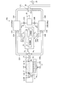
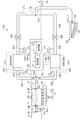
- FIG. 1 is a schematic view showing a diesel engine provided with the exhaust gas processing device according to the present embodiment.
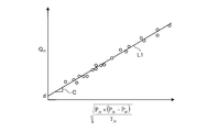
- FIG. 2 is a view showing the relationship between the total flow rate of exhaust gas and the pressure parameter obtained using the actually measured junction pressure, the total flow rate of exhaust gas, the junction temperature and the atmospheric pressure.
- FIG. 3 is a flowchart showing an example of processing for obtaining the junction pressure in the exhaust gas processing method according to the present embodiment.
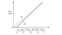
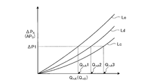
- FIG. 4 is a view showing the relationship between the flow rate and the pressure parameter in the first reduction catalyst.
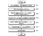
- FIG. 5 is a processing flow diagram of the exhaust gas treatment method according to the present embodiment.
- FIG. 6 is a schematic view showing a diesel engine provided with an exhaust gas processing device according to a first modification of the present embodiment.
- FIG. 7 is a schematic view showing a diesel engine provided with an exhaust gas processing system according to a second modification of the embodiment.
- FIG. 8 is a diagram showing an example of the relationship between the first differential pressure and the second differential pressure, and the flow rate of the exhaust gas flowing through the first DPF and the second DPF, with different amounts of soot deposited on the first DPF and the second DPF. It is.
- FIG. 9 is a flowchart showing an example of exhaust gas treatment using the exhaust gas treatment system according to the second modification.
- the flow rate of the fluid that is, the amount of intake air, the flow rate of the exhaust gas, etc. are all mass flow rates.
- FIG. 1 is a schematic view showing a diesel engine provided with the exhaust gas processing device according to the present embodiment.
- the diesel engine 10 includes an exhaust gas processing device 20.
- the exhaust gas processing device 20 will be described later.
- the diesel engine 10 and the exhaust gas processing device 20 are controlled by a controller 50.
- the diesel engine 10 includes a fuel injection device 11 and an intake pipe 12 as an intake passage. Further, an exhaust pipe 21 as an exhaust gas introduction passage provided in the exhaust gas processing device 20 is attached to the exhaust port 16 of the diesel engine 10.
- An air cleaner 13 for removing dust in the air is attached to the inlet 12I of the intake pipe 12.
- an outlet 12 ⁇ / b> E is attached to an intake port 17 of the diesel engine 10.
- An intake air amount sensor 14 is attached to the intake pipe 12.
- the intake air amount sensor 14 detects the flow rate (mass flow rate in the present embodiment) of the air AI which passes through the intake pipe 12 and is sucked into the diesel engine 10.
- the intake air amount sensor 14 is electrically connected to the control device 50. With such a structure, the control device 50 acquires the measurement value of the intake air amount sensor 14.
- the control device 50 uses the measurement value of the intake air amount sensor 14 for control of the diesel engine 10 including control of the exhaust gas processing device 20.
- the fuel injection device 11 supplies fuel to the diesel engine 10. More specifically, fuel is injected into a combustion chamber corresponding to each cylinder 10C of the diesel engine 10.
- the fuel injection device 11 is a so-called common rail type device including a pressure accumulation chamber 11R and an injector 11I.
- the fuel injection device 11 is controlled by the control device 50. Specifically, for example, the control device 50 causes the injector 11I to inject an appropriate amount of fuel according to operating conditions such as the rotation speed and load of the diesel engine 10.
- the fuel injection device 11 is not limited to the common rail system.
- the exhaust gas processing device 20 is a device for purifying the exhaust gas EX discharged from the diesel engine 10.
- the exhaust gas processing device 20 mainly reduces NOx (nitrogen oxide) contained in the exhaust gas EX.
- the exhaust gas processing apparatus 20 includes a first branch pipe 22A as a first exhaust gas passage and a second branch pipe 22B as a first exhaust gas passage, and a first exhaust gas purification unit 20A and a second exhaust gas purification unit. It includes an exhaust gas purification unit 20B, a second exhaust gas passage 26, a first temperature sensor 28A and a second temperature sensor 28B as exhaust gas temperature sensors, an atmospheric pressure sensor 29, and a processing unit 51.
- the first branch pipe 22A and the second branch pipe 22B as the plurality of first exhaust gas passages are a plurality of passages which allow the exhaust gas EX discharged by the diesel engine 10 to be branched into a plurality of passages.
- the first branch pipe 22A and the second branch pipe 22B are branched from the exhaust pipe 21 as an exhaust gas introduction passage.
- the exhaust pipe 21 discharges the exhaust gas EX discharged by the diesel engine 10.
- the exhaust pipe 21 guides the exhaust gas EX to the first branch pipe 22A and the second branch pipe 22B of the exhaust gas processing device 20.
- the exhaust gas EX flowing through the exhaust pipe 21 is branched into the first branch pipe 22A and the second branch pipe 22B at a branch portion 21S where the first branch pipe 22A and the second branch pipe 22B branch from the exhaust pipe 21. .
- the first exhaust gas purification unit 20A and the second exhaust gas purification unit 20B as the exhaust gas purification unit are provided in the first branch pipe 22A and the second branch pipe 22B, respectively, and purify the exhaust gas EX.
- the second exhaust gas passage 26 is a passage provided in a portion where the first branch pipe 22A and the second branch pipe 22B merge.
- the second exhaust gas passage 26 discharges the exhaust gas EX discharged from the first branch pipe 22A and the second branch pipe 22B.
- the first branch pipe 22A and the second branch pipe 22B merge on the downstream side of the first exhaust gas purification unit 20A and the second exhaust gas purification unit 20B.
- the upstream side is the upstream side in the flow direction of the exhaust gas EX in the exhaust gas treatment device 20
- the downstream side is the downstream in the flow direction of the exhaust gas EX in the exhaust gas treatment device 20 It is the side.
- the first temperature sensor 28A and the second temperature sensor 28B as exhaust gas temperature sensors detect the temperature of the exhaust gas EX.
- the first temperature sensor 28A is provided to the first branch pipe 22A.
- the second temperature sensor 28B is provided to the second branch pipe 22B. More specifically, the first temperature sensor 28A is provided upstream of the first catalyst 25A as a reduction catalyst included in the first exhaust gas purification unit 20A as an exhaust gas purification unit.
- the second temperature sensor 28B is provided on the upstream side of the second catalyst 25B as a reduction catalyst included in the second exhaust gas purification unit 20B as an exhaust gas purification unit.
- the first catalyst 25A and the second catalyst 25B will be described later.
- the first temperature sensor 28A detects the temperature of the exhaust gas EX flowing through the first branch pipe 22A.
- the second temperature sensor 28B detects the temperature of the exhaust gas EX flowing through the second branch pipe 22B.
- the first temperature sensor 28A may detect the temperature of the exhaust gas EX in the first catalyst 25A
- the second temperature sensor 28B may detect the temperature of the exhaust gas EX in the second catalyst 25B.
- Atmospheric pressure sensor 29 is a pressure sensor for detecting the atmospheric pressure P at.
- the processing unit 51 executes the exhaust gas processing method according to the present embodiment, and the pressure of a portion (hereinafter referred to as a merging portion as appropriate) 22J where the first exhaust gas purification unit 20A and the second exhaust gas purification unit 20B merge Find the junction pressure ( Pjn ) as appropriate. This is because the junction pressure P jn is required to obtain the flow rate of the exhaust gas EX flowing through the first branch pipe 22A and the second branch pipe 22B.
- the processing unit 51 sets the relationship between the junction pressure Pjn, the total flow rate Qm of the exhaust gas EX discharged by the diesel engine 10, the temperature of the exhaust gas EX, and the atmospheric pressure Pat at the time of operation of the diesel engine 10.
- total flow rate Q m and the exhaust gas temperature sensor of the resulting exhaust gas EX is obtained by giving the atmospheric pressure P at that temperature and the atmospheric pressure sensor 29 of the exhaust gas EX detected was detected.
- the total flow rate Q m of the exhaust gas EX is the exhaust gas total flow rate detection unit is determined during operation of the diesel engine 10.
- the exhaust gas total flow rate detection unit will be described later.
- the merging portion 22J described above is also a portion where the plurality of first exhaust gas passages merge, that is, a portion where the first branch pipe 22A and the second branch pipe 22B merge.
- the first exhaust gas purification unit 20A and the second exhaust gas purification unit 20B as an exhaust gas purification unit are a first DPF (Diesel Particulate Filter) 23A and a second DPF 23B as particulate filters, and a reduction catalyst for reducing NOx (
- the first catalyst 25A and the second catalyst 25B are appropriately included as a NOx reduction catalyst).
- the exhaust gas processing apparatus 20 mainly uses a technology for treating an exhaust gas called urea SCR, which reduces NOx contained in the exhaust gas EX using a NOx reduction catalyst as a selective catalyst and a reducing agent.
- the technology for treating the exhaust gas EX is not limited to this.
- the temperature of the exhaust gas EX used in the exhaust gas treatment method according to the present embodiment is the temperature of the exhaust gas EX at the junction 22J (referred to as the junction temperature appropriately) Tjn .
- the junction temperature Tjn may be detected by providing an exhaust gas temperature sensor at the junction 22J. Further, if the junction temperature T jn is downstream of the first DPF 23A and the second DPF 23B, the influence on the value of the junction pressure P jn obtained by the processing unit 51 is small. For this reason, in the present embodiment, at least one of the first temperature sensor 28A and the second temperature sensor 28B is used as an exhaust gas temperature sensor for determining the junction temperature T jn . It the temperature of the exhaust gas EX either one of these is detected may merging portion temperature T jn, the average value of the temperature of both the detected exhaust gas EX may merging portion temperature T jn.
- the first catalyst 25A as the NOx reduction catalyst is provided in the first branch pipe 22A
- the second catalyst 25B is provided in the second branch pipe 22B.
- the first catalyst 25A and the second catalyst 25B reduce NOx in the exhaust gas EX by the reducing agent R. That is, the first catalyst 25A and the second catalyst 25B are provided in the first branch pipe 22A and the second branch pipe 22B as the first exhaust gas passages, respectively, and reduce NOx in the exhaust gas EX.
- the reducing agent R is generated by the reducing agent supply device 30 in the first branch pipe 22A on the upstream side of the first catalyst 25A as the NOx reduction catalyst and in the second branch pipe on the upstream side of the second catalyst 25B as the NOx reduction catalyst.
- the required amount is supplied to the inside of 22B.
- the reducing agent supply device 30 includes a reducing agent tank 31, a first pump 32A, a second pump 32B, a first injection device 33A, and a second injection device 33B.
- the control device 50 controls the first pump 32A, the second pump 32B, the first injection device 33A, and the second injection device 33B.
- the first injection device 33A injects the reducing agent R pressure-fed by the first pump 32A from the reducing agent tank 31 into the inside of the first branch pipe 22A. Further, the second injection device 33B injects the reducing agent R pressure-fed by the second pump 32B from the reducing agent tank 31 into the inside of the second branch pipe 22B.
- the reducing agent R is urea (more specifically, urea water).
- the reducing agent R supplied into the first branch pipe 22A and the second branch pipe 22B is decomposed by the heat of the exhaust gas EX and is converted to ammonia.
- NOx and ammonia cause a catalytic reaction to be converted into nitrogen and water.
- the exhaust gas processing apparatus 20 converts NOx contained in the exhaust gas EX into nitrogen and water using selective catalytic reduction using urea as the reducing agent R, so-called urea SCR.
- the NOx reduction catalyst converts NOx into nitrogen and water by a reducing agent that reduces NOx.
- a vanadium-based catalyst or a zeolite-based catalyst is used as the NOx reduction catalyst.
- the exhaust gas processing device 20 may be provided with an oxidation catalyst (AMOX: ammonia oxidation catalyst) for purifying ammonia on the downstream side of the first catalyst 25A and the second catalyst 25B in the flow direction of the exhaust gas EX.
- AMOX ammonia oxidation catalyst
- the first DPF 23A is provided upstream of the first catalyst 25A as a NOx reduction catalyst
- the second DPF 23B is provided upstream of the second catalyst 25B as a NOx reduction catalyst.
- an oxidation catalyst for example, DOC: Diesel Oxidation Catalyst
- DOC Diesel Oxidation Catalyst
- the exhaust gas processing apparatus 20 includes, as components, a first pressure sensor 27A and a second pressure sensor 27B as pressure sensors, and an NOx detection sensor 15, in addition to the components described above.
- the first pressure sensor 27A is disposed upstream of the first catalyst 25A as a NOx reduction catalyst
- the second pressure sensor 27B is disposed upstream of the second catalyst 25B as a NOx reduction catalyst.
- the first pressure sensor 27A detects the pressure in the first branch pipe 22A as the first exhaust gas passage on the upstream side of the first catalyst 25A.
- the second pressure sensor 27B detects the pressure in the second branch pipe 22B as the first exhaust gas passage on the upstream side of the second catalyst 25B.
- the NOx detection sensor 15 detects the concentration of NOx contained in the exhaust gas EX emitted by the diesel engine 10. If the operating conditions of the diesel engine 10 are the same, the concentration of NOx contained in the exhaust gas EX does not change before passing through the first catalyst 25A and the second catalyst 25B as the NOx reduction catalyst. For this reason, the location where the NOx detection sensor 15 is provided is not limited to the exhaust pipe 21 as the exhaust gas introduction passage. For example, the NOx detection sensor 15 may be provided in the branch portion 21S, or may be provided in the first branch pipe 22A or the second branch pipe 22B. For this reason, the NOx detection sensor 15 has a relatively high degree of freedom in arrangement.
- the NOx detection sensor 15 is disposed downstream of the exhaust port 16 of the diesel engine 10 and upstream of the first catalyst 25A and the second catalyst 25B as the NOx reduction catalyst. Good.
- the aforementioned intake air amount sensor 14, the first temperature sensor 28A, the second temperature sensor 28B, the atmospheric pressure sensor 29, the NOx detection sensor 15, the first pressure sensor 27A and the second pressure sensor 27B are electrically connected to the control device 50. It is connected.
- the control device 50 acquires detection values of these sensors, and implements the exhaust gas processing method according to the present embodiment. Next, the control device 50 will be described.
- Control device 50 For example, a microcomputer unit is used as the control device 50.
- the control device 50 includes a processing unit 51 and a storage unit 52.
- the processing unit 51 is, for example, a central processing unit (CPU)
- the storage unit 52 is, for example, random access memory (RAM), read only memory (ROM), erasable programmable read only memory (EPROM), or electrically erasable memory (EEPROM). Programmable Read-Only Memory) or a combination thereof.
- the processing unit 51 executes various controls on the diesel engine 10 in addition to executing the exhaust gas processing method according to the present embodiment.
- the storage unit 52 stores a computer program for executing the various controls described above and information necessary for various controls.
- the processing unit 51 reads the computer program described above from the storage unit 52, and executes the instructions described therein.
- the processing unit 51 reads out information necessary for control from the storage unit 52 as needed, and various kinds of information such as the intake air amount sensor 14, the first temperature sensor 28A, the second temperature sensor 28B, the atmospheric pressure sensor 29, etc. Information on the state of the diesel engine 10 is acquired from the sensors.
- the control device 50 includes an intake air amount sensor 14, a first temperature sensor 28A, a second temperature sensor 28B, an atmospheric pressure sensor 29, an NOx detection sensor 15, a first pressure sensor 27A, a second pressure sensor 27B, and the like.
- the amount of reducing agent R supplied to the first catalyst 25A and the second catalyst 25B is controlled based on at least the detected value.
- the control device 50 may detect the intake air amount sensor 14, the first temperature sensor 28A, the second temperature sensor 28B, the atmospheric pressure sensor 29, the first pressure sensor 27A, and the second pressure sensor 27B.
- the flow rate of the exhaust gas EX flowing through the first branch pipe 22A upstream of the first catalyst 25A and the second branch pipe 22B upstream of the second catalyst 25B is determined.
- the control device 50 obtains the first branch pipe 22A and the second branch pipe 22A from the obtained flow rate of the exhaust gas EX in the first branch pipe 22A and the second branch pipe 22B and the concentration of NOx in the exhaust gas EX detected by the NOx detection sensor 15. The flow rate of NOx in the branch pipe 22B is determined. Thereafter, the control device 50 obtains the amount of reducing agent R to be provided to the first catalyst 25A and the second catalyst 25B from the obtained flow rate of NOx in the first branch pipe 22A and the second branch pipe 22B.
- the control device 50 When determining the flow rate of the exhaust gas EX in the first branch pipe 22A and the second branch pipe 22B, the control device 50 performs the first operation based on the detection values of the first pressure sensor 27A and the second pressure sensor 27B and the junction pressure P jn . The flow ratio of the exhaust gas EX flowing through the branch pipe 22A and the second branch pipe 22B is determined. Next, the control unit 50, based on the total flow rate Q m of the resulting flow rate ratio and the exhaust gas EX, determine the flow rate of the exhaust gas EX flowing through the first branch pipe 22A and the second branch pipe 22B.
- the total flow rate Q m of the exhaust gas EX is the total flow rate of the exhaust gas EX diesel engine 10 is discharged, which corresponds to the flow rate of the exhaust gas EX flowing through the exhaust pipe 21.
- the total flow rate Q m of the exhaust gas EX is determined by the exhaust gas total flow rate detecting unit described above.
- the control device 50 and sensors such as the intake air amount sensor 14 correspond to the exhaust gas total flow rate detection unit.
- the total flow rate of the exhaust gas EX can be determined, for example, from the amount of intake air of the diesel engine 10 and the amount of fuel injection to the diesel engine 10.
- the intake air amount of the diesel engine 10 can be detected by an intake air amount sensor 14.
- the fuel injection amount for the diesel engine 10 is calculated from the operating conditions of the diesel engine 10 by the control device 50 that controls the diesel engine 10.
- the first pressure sensor 27A is provided between the first DPF 23A and the first catalyst 25A
- the second pressure sensor 27B is provided between the second DPF 23B and the second catalyst 25B. Since the first DPF 23A and the second DPF 23B rectify the exhaust gas EX, the detection accuracy of the first pressure sensor 27A and the second pressure sensor 27B is improved by the arrangement described above.
- the exhaust gas processing apparatus 20 branches the path of the exhaust gas EX into a plurality of systems (two systems in the present embodiment) and is disposed in each of the passages.
- the exhaust gas EX is processed by the NOx reduction catalyst.
- the exhaust gas processing apparatus 20 needs to accurately determine the flow rate of the exhaust gas EX flowing to the first catalyst 25A and the second catalyst 25B that the exhaust gas processing apparatus 20 accurately supplies to the first catalyst 25A and the second catalyst 25B. Therefore, when processing the exhaust gas EX discharged from the diesel engine 10, the exhaust gas processing apparatus 20 executes the exhaust gas processing method according to the present embodiment to obtain the flow rate of the exhaust gas EX flowing through the plurality of NOx reduction catalysts. Improve the accuracy of
- the compressor of the turbocharger when the diesel engine 10 is provided with a turbocharger, the compressor of the turbocharger is disposed downstream of the intake air amount sensor 14 shown in FIG. 1 (downstream in the flow direction of the air AI). Then, the compressor compresses the air AI after the flow rate is measured by the intake air amount sensor 14. Further, the flow rate of the air AI measured by the intake air amount sensor 14 is a mass flow rate. Therefore, even if the diesel engine 10 is equipped with a turbocharger, measurement of the flow rate of the air AI taken into the diesel engine 10 is not affected. Therefore, there is no impact on the calculation of the total flow rate Q m of the exhaust gas EX described above.
- the diesel engine 10 may be provided with an EGR (Exhaust Gas Recirculation) device.
- the EGR device is a device for returning a part of the exhaust gas EX discharged by the diesel engine 10 to the intake side, more specifically, to the intake pipe 12.
- EGR exhaust Gas Recirculation
- a portion of the exhaust gas EX diesel engine 10 is discharged is only returning to the intake side, not there is a change in total flow rate Q m of the exhaust gas EX as a whole a diesel engine 10. Therefore, even if the diesel engine 10 is equipped with EGR, no effect on the calculation of the total flow rate Q m of the exhaust gas EX described above.
- the exhaust gas EX processed and discharged by the exhaust gas processing apparatus 20 is supplied to, for example, the heating pipe 101 provided in the vessel 100 in order to heat the vessel 100 of the dump truck.
- the second exhaust gas passage 26 is connected to the inlet 102 of the heating pipe 101.
- the exhaust gas processing device 20 causes the first branch pipe 22A and the second branch pipe 22B to join at the joining portion 22J, and discharges the single second exhaust gas passage 26.
- the amount of reducing agent supplied to the first catalyst 25A provided to the first branch pipe 22A and the second catalyst 25B provided to the second branch pipe 22B is controlled, and the amount of soot deposited on the first DPF 23A and the second DPF 23B It is necessary to obtain the flow rates of the exhaust gas EX flowing through the first branch pipe 22A and the second branch pipe 22B, respectively. For this purpose, it is necessary to know the pressure of each of the exhaust gases EX flowing through the first branch pipe 22A and the second branch pipe 22B.
- the structure in which the first branch pipe 22A and the second branch pipe 22B are joined at the joint portion 22J and discharged from one second exhaust gas passage 26 is the first branch pipe 22A due to the influence of the pipe resistance of the joint portion 22J.
- the respective flow rates can not be accurately determined.
- the heating pipe 101 of the vessel 100 is connected to the second exhaust gas passage 26.
- the merging portion it is also conceivable to reduce the pipe resistance by thickening the heating pipe 101 downstream of 22J.
- the heating pipe 101 is long and bent, it is necessary to take a large space for the heating pipe 101 if such a pipe is thickened, which can cause a drastic design change of the heating pipe 101. There is sex. Therefore, practically, it is difficult to reduce the pipe resistance of the heating pipe 101.
- the second exhaust gas passage 26 provided downstream of the merging portion 22J is usually connected to a silencer and a pipe for guiding the exhaust gas EX thereto. Further, in the present embodiment, the second exhaust gas passage 26 is connected to the heating pipe 101 of the vessel 100 shown in FIG. 1.
- the second exhaust gas passage 26, the piping 101 for heating, the piping connected downstream of the second exhaust gas passage 26, devices such as a silencer, etc. are disposed between the first branch pipe 22A and the second branch pipe 22B and the atmosphere.
- the exhaust gas EX flow resistance at In addition, the merging portion 22J also serves as a flow resistance of the exhaust gas EX between the first branch pipe 22A and the second branch pipe 22B and the atmosphere.
- the flow rate of the exhaust gas EX at the merging portion 22J is a flow rate discharged to the atmosphere from the first branch pipe 22A and the second branch pipe 22B. This flow rate is equal to the total flow rate Q m of the exhaust gas EX diesel engine 10 is discharged. Therefore, the total flow rate Q m can be expressed by equation (1) using the differential pressure between the junction pressure P jn and the atmospheric pressure P at and the junction temperature T jn .
- C in Formula (1) is a constant.
- the processing unit 51 of the control device 50 merges in obtaining the parts pressure P jn, the relationship between the total flow rate Q m of the joining portion pressure P jn the exhaust gas and the confluent portion temperature T jn the atmospheric pressure P at, for example, obtained in advance by experiment or the like.
- FIG. 2 is a view showing the relationship between the total flow rate of exhaust gas and the pressure parameter obtained using the actually measured junction pressure, the total flow rate of exhaust gas, the junction temperature and the atmospheric pressure.
- the total flow rate Q m of the exhaust gas EX on the vertical axis expressed merging portion pressure P jn at that time, the pressure parameters obtained from the merging portion temperature T jn, and the atmospheric pressure P at the horizontal axis, the total flow rate Q
- the relationship between m and the pressure parameter is shown.
- a plurality of white circles shown in FIG. 2 are actually measured values.
- the straight line L1 in FIG. 2 is approximated by a linear function as shown in the equation (1) in which the total flow rate Q m is a linear expression of the pressure parameter.
- Relationship between the total flow rate Q m and the pressure parameter is theoretically a linear function of the slope c passing through the origin.
- the heating pipe 101 of the vessel 100 shown in FIG. 1, the silencer, etc. the junction pressure P jn , the total exhaust gas flow rate Q m , the junction temperature T jn and the atmospheric pressure
- an approximate expression is determined using the least square method or the like from the flow rate Q mA and pressure parameters determined by actually measuring P at , a linear function not passing through the origin as shown by the solid line L1 in FIG. 2 It can be In this case, the accuracy of the merging portion pressure P jn is improved by using the approximate expression based on the actual measurement.
- the relationship between the flow rate Q mA and the pressure parameter is a linear function
- the function representing the relationship between the two is not limited to this.
- the relationship between the two may be represented by various functions such as a quadratic function, a cubic function, an n-th function (n is a real number), or an exponential function.
- Expression (2) is a relational expression between the total flow rate Q m and the pressure parameter in the case of a linear function not passing through the origin based on the actual measurement.
- C and d in equation (2) are constants.
- the constant c is the slope of a linear function passing through the origin or a linear function not passing through the origin as shown by the solid line L1 in FIG.
- Constant d is the linear function that does not pass through the origin, as shown by a linear function or a solid line L1 passing through the origin, which is the value of intercept in Q m axis. Relationship between the total flow rate Q m and pressure parameters, when a linear function passing through the origin, the sections 0, so the constant d is zero.
- the constants c and d can be determined from a linear function representing a straight line passing through the origin or a linear function representing a straight line L1 as shown in FIG.
- the constants c and d may be determined based on actual measurement, or may be determined by simulation or theoretical calculation or the like.
- the measured values in Fig. 2 when the total flow rate Q m is approximated by a linear equation of the pressure parameter, the equation (2).
- the straight line L1 in FIG. 2 corresponds to the equation (2).
- Constant c of the formula (2) becomes the slope of the straight line L1 in FIG. 2, the constant d is a value of the intercept in the linear L1 and Q m-axis in FIG.
- the correlation coefficient of the above-mentioned approximation is 0.99, and it can be seen that the equation (2) has a very high correlation with the measured value.
- Equation (3) is obtained by solving equation (2) for the junction pressure P jn .
- the equation (3) represents the relationship between the junction pressure P jn , the total flow rate Q m of the exhaust gas EX, the junction temperature T jn, and the atmospheric pressure P at .
- the merging unit pressure P jn can be expressed by the relational expression between the total flow rate Q m and merging portion temperature T jn and the atmospheric pressure P at the exhaust gas EX.
- FIG. 3 is a flowchart showing an example of processing for obtaining the junction pressure in the exhaust gas processing method according to the present embodiment.
- the processing unit 51 of the control device 50 calculates the intake air amount M Ar detected by the intake air amount sensor 14 and the fuel injection amount M calculated by the control device 50 from the operating conditions of the diesel engine 10.
- obtaining a fl and the exhaust gas temperature such as the first temperature sensor 28A detects, and the atmospheric pressure P at the atmospheric pressure sensor 29 has been detected (step S101).
- the exhaust gas temperature corresponds to the junction temperature T jn .
- the temperatures T A and T B of the exhaust gas EX on the upstream side of the first catalyst 25A or the second catalyst 25B can be used.
- Atmospheric pressure P at the other detection values the atmospheric pressure sensor 29 detects the average atmospheric pressure may be used as a constant.
- the total flow rate Q m of the exhaust gas EX for example, the intake air amount M Ar of the diesel engine 10 intake air quantity sensor 14 that the diesel engine 10 is provided to detect the fuel injector 11 per unit time injected into the diesel engine 10 ( For example, it can be determined by the sum of the amount of fuel (fuel injection amount) M Fl (mass) per second).
- Processing unit 51 from the intake air amount M Ar of the intake air quantity sensor 14 detects a fuel injection amount M Fl of the controller 50 is calculated to obtain the total flow rate Q m of the exhaust gas EX.
- processor 51 may determine the total flow rate Q m of the exhaust gas EX using the air-fuel ratio.
- the fuel injection quantity M Fl obtained from the intake air amount M Ar and the air-fuel ratio it may be calculated on the total flow rate Q m of the exhaust gas EX.
- the processing unit 51 obtains the intake air amount M Ar of the diesel engine 10 from the fuel injection amount M Fl and the air fuel ratio, and the exhaust gas EX from the fuel injection amount M Fl and the intake air amount M Ar obtained from the air fuel ratio.
- the total flow rate Q m of may be determined.
- the air-fuel ratio can be a representative value under the operating conditions of the diesel engine 10.
- the intake air amount M Ar is further obtained from the volumetric efficiency of the diesel engine 10, the temperature, pressure, and flow rate of the intake air, and the total flow rate of the exhaust gas EX from this and the fuel injection amount M Fl. Q m may be obtained.
- the total flow rate Q m of the exhaust gas EX can be determined by several techniques.
- the detection value of the sensor such as the intake air quantity sensor 14 control unit 50 of the processing section 51 acquires, obtains the total flow rate Q m of the exhaust gas EX performs some computation on the detection value described above Be Therefore, in the present embodiment, the processing unit 51 of the control device 50 and the sensors such as the intake air amount sensor 14 correspond to the exhaust gas total flow rate detection unit for obtaining the total flow rate of the exhaust gas EX discharged by the diesel engine 10. .
- step S102 the processing unit 51 reads the equation (3) or the map stored in the storage unit 52. Then, the processing unit 51 gives the obtained total flow rate Q m of the exhaust gas EX, the acquired exhaust gas temperature and the atmospheric pressure Pat to the read equation (3) or a map. The exhaust gas temperature is given to the equation (3) or the map as the junction temperature T jn . Then, since the equation (3) or the map calculates the junction pressure P jn , the processing unit 51 can obtain the junction pressure P jn (step S102).
- the exhaust gas processing device 20 a merging unit pressure PT jn, total flow rate Q m of the exhaust gas EX, previously obtained by experiment or the like relationship between the confluent portion temperature T jn, and the atmospheric pressure P at, the equation Use junction pressure PT jn to find.
- the exhaust gas processing apparatus 20 accurately uses the junction pressure P jn necessary to obtain the flow rate of the exhaust gas EX flowing through the first branch pipe 22A and the second branch pipe 22B without using a pressure sensor. It can be easily obtained.
- the exhaust gas processing device 20 can determine the flow rate of the exhaust gas EX flowing through the first branch pipe 22A and the second branch pipe 22B accurately and simply.
- the exhaust gas processing device 20 does not need a pressure sensor for detecting the junction pressure P jn , an increase in cost can be suppressed.
- a method of determining the flow rate of each exhaust gas EX flowing through each branch pipe, that is, the first branch pipe 22A and the second branch pipe 22B will be described.
- the flow rate of each branch pipe is at least the junction pressure P jn , the pressure of the exhaust gas EX upstream of the first catalyst 25A provided in the first branch pipe 22A, and The pressure can be obtained from the pressure of the exhaust gas EX on the upstream side of the second catalyst 25B provided in the 2-branch pipe 22B.
- the measured temperature of the exhaust gas EX on the upstream side of the first catalyst 25A provided in the first branch pipe 22A and the temperature of the exhaust gas EX on the upstream side of the second catalyst 25B provided in the second branch pipe 22B It is preferable to measure and use the flow rate of each branch pipe more accurately.
- the first catalyst 25A and the second catalyst 25B are, for example, those in which a NOx reduction catalyst is supported on a carrier having a plurality of passages through which a fluid flows. Therefore, the first catalyst 25A and the second catalyst 25B provided in the exhaust gas processing device 20 serve as resistors when the exhaust gas EX flows. Therefore, the first catalyst 25A and the second catalyst 25B can be regarded as resistors of the first branch pipe 22A and the second branch pipe 22B, respectively.
- the flow rate of the exhaust gas EX flowing through the first catalyst 25A (referred to as the first flow rate as appropriate) Q mA and the flow rate of the exhaust gas EX flowing through the second catalyst 25B (referred to as the second flow rate as appropriate) QmB are Formula (4) and Formula (5) can represent.
- the first flow rate Q mA and the second flow rate Q mB are both mass flow rates.
- ⁇ (P Au ⁇ (P Au ⁇ P Ad ) / T A ) and ⁇ (P Bu ⁇ (P Bu ⁇ P Bd )), which are the square roots of the right sides of Formula (4) and Formula (5) Let / T B ) be a pressure parameter as appropriate.
- PAu is a detected value of the first pressure sensor 27A, a pressure of the exhaust gas EX flowing in the first branch pipe 22A on the upstream side of the first catalyst 25A
- PBu is a detected value of the second pressure sensor 27B
- P Ad is the pressure of the exhaust gas EX flowing in the first branch pipe 22A downstream of the first catalyst 25A
- P Bd is the pressure of the exhaust gas EX flowing in the second branch pipe 22B downstream of the second catalyst 25B.
- P Ad and P Bd have the same value as the junction pressure P jn .
- K is a constant and a ⁇ C ⁇ A ⁇ ⁇ (R).
- a is a constant
- C is a flow coefficient of the first catalyst 25A or the second catalyst 25B
- A is a total cross-sectional area of the passage through which the exhaust gas EX flows in the first catalyst 25A or the second catalyst 25B (as appropriate, the passage area)
- R is It is a gas constant.
- the constant k is individually determined from the respective flow coefficient and passage area. May be determined. Also, k may be determined from a, C, A, R using the above equation, or may be determined based on actual measurement as described later.
- T A is the temperature of the exhaust gas EX on the upstream side of the first catalyst 25A, the temperature of the exhaust gas EX immediately before flowing into the first catalyst 25A (appropriately referred to as a first temperature).
- T B is the temperature of the exhaust gas EX on the upstream side of the second catalyst 25B, the temperature of the exhaust gas EX immediately before flowing into the second catalyst 25B (properly referred to as a second temperature). Since the exhaust gas processing device 20 includes the first temperature sensor 28A and the second temperature sensor 28B, the detection values of these can be used as the temperatures T A and T B. Also, for example, the temperatures T A and T B may be estimated from the detection value of the exhaust gas temperature sensor provided in the diesel engine 10.
- the temperatures T A and T B can be estimated by correcting the detected values of the exhaust gas temperature sensor based on the heat release amount of the first branch pipe 22A, the second branch pipe 22B, the first DPF 23A, and the second DPF 23B. .
- the temperatures T A and T B may be regarded as the same.
- the first catalyst 25A and the second catalyst 25B can be regarded as resistors of the first branch pipe 22A and the second branch pipe 22B, respectively.
- the exhaust gas processing device 20 controls the pressure of the exhaust gas EX flowing through the first branch pipe 22A and the pressure of the exhaust gas EX flowing through the second branch pipe 22B, more specifically, the first on the upstream side of the first catalyst 25A.
- the pressure of the exhaust gas EX flowing through the branch pipe 22A and the pressure of the exhaust gas EX flowing through the second branch pipe 22B upstream of the second catalyst 25B can be reliably detected by the first pressure sensor 27A and the second pressure sensor 27B.
- the first catalyst 25A is provided downstream of the first pressure sensor 27A as a fluid resistance
- the second catalyst 25B is provided downstream of the second pressure sensor 27B as a fluid resistance. Therefore, the pressure and the pressure change of the exhaust gas EX can be secured on the upstream side of the first catalyst 25A and the second catalyst 25B.
- the exhaust gas processing apparatus 20 can measure the exhaust gas EX in a relatively high pressure state, so the pressure of the exhaust gas EX used when determining the first flow rate Q mA and the second flow rate Q mB , that is, the first It is possible to suppress a decrease in accuracy when the pressure of the exhaust gas EX flowing through the branch pipe 22A and the pressure of the exhaust gas EX flowing through the second branch pipe 22B are measured.
- the exhaust gas processing apparatus 20 improves the accuracy in determining the first flow rate Q mA and the second flow rate Q mB. It can be done.
- the exhaust gas processing device 20 can accurately supply an appropriate amount of reducing agent to the first catalyst 25A and the second catalyst 25B.
- FIG. 4 is a view showing the relationship between the flow rate and the pressure parameter in the first reduction catalyst.
- the straight line La of the dashed-dotted line in FIG. 4 represents the flow rate Q mA (Q mB ) represented by the equation (4) and the pressure parameter ⁇ (P Au ⁇ (P Au ⁇ P Ad ) / T A ) (or ⁇ (P Bu ⁇ ) (P Bu -P Bd ) / T B )) is shown.
- the relationship between the two is a linear function of a slope k passing through the origin, as theoretically shown by a straight line La.
- a linear line Lb in solid line in FIG. It may be a linear function that does not pass through the origin.
- the accuracy of the first flow rate Q mA and the second flow rate Q mB is improved by using an approximate expression based on actual measurement.
- the relationship between the flow rate Q mA and the pressure parameter is a linear function, but the function representing the relationship between the two is not limited to this.
- the relationship between the two may be represented by various functions such as a quadratic function, a cubic function, an n-th function (n is a real number), or an exponential function.
- Equations (6) and (7) show the equations of the first flow rate Q mA and the second flow rate Q mB in the case of a linear function not passing through the origin based on the actual measurement.
- A1 and A2 of Formula (6) and B1 and B2 of Formula (7) are constants.
- the constant A1 is, for example, a linear function passing through the origin as shown by a straight line La shown by a dashed dotted line in FIG. 4 or a slope of the linear function not passing through the origin as shown by a solid straight line Lb.
- the constant A2 is the value of the intercept on the Q mA axis of a linear function passing through the origin as indicated by the dashed dotted straight line La or a linear function not passing through the origin as indicated by the solid straight line Lb. If the relationship between the flow rate Q mA and the pressure parameter is a linear function passing through the origin as shown by the dashed-dotted straight line La, the intercept is 0, so the constant A2 is 0. Therefore, the constants A1 and A2 can be determined from a linear function representing a straight line La or a straight line Lb as shown in FIG.
- the constants B1 and B2 are also the same as the constants A1 and A2.
- the constants A1, A2, B1, and B2 may be determined based on actual measurement, or may be determined by simulation or theoretical calculation or the like.
- the amount of NOx flowing through the first catalyst 25A and the second catalyst 25B can be known. Therefore, it is possible to determine the amount of reducing agent R necessary to convert all the NOx flowing through the first catalyst 25A and the second catalyst 25B into nitrogen and water.
- the amount of the necessary reducing agent R described above can be represented by Formula (10) and Formula (11).
- Q mAur is the amount of reducing agent R required for the first catalyst 25A
- QmBur is the amount of reducing agent R required for the second catalyst 25B.
- ⁇ is ANR (Ammonia to NOx Ratio: ratio of ammonia to NOx)
- the first example of the exhaust gas processing method according to the present embodiment uses the pressure of at least the pressure of the first branch pipe 22A and the second branch pipe 22B on the upstream side of the first catalyst 25A and the second catalyst 25B.
- the accuracy in measuring the flow rate Q mA and the second flow rate Q mB can be improved. Therefore, in the first example, since the flow rate of NOx flowing through the first catalyst 25A and the second catalyst 25B can be accurately determined, the first catalyst 25A and the second catalyst 25A can be obtained by using the obtained flow rate of NOx. An appropriate amount of reducing agent R can be accurately supplied to the catalyst 25B.
- the second example of the method of obtaining the flow rate of each branch pipe is the same as the first example described above, but the first one on the upstream side of the first catalyst 25A and the second catalyst 25B.
- the flow ratio Q mA / Q mB which is the ratio of the first flow rate Q mA to the second flow rate Q mB determined based on the pressure of the first branch pipe 22A and the second branch pipe 22B, and the exhaust gas discharged by the diesel engine 10 by using the total flow rate Q m of EX, that determine the flow rate of the branch pipes are different.
- Equation (12) Ru The flow ratio ⁇ determined based on the pressure of the first branch pipe 22A on the upstream side of the first catalyst 25A and the pressure of the second branch pipe 22B on the upstream side of the second catalyst 25B is expressed by Equation (12) Ru.
- the first flow rate Q mA and the second flow rate Q mB in the equation (12) can be obtained from the equations (4) and (5) described above, respectively. If the first temperature T A and the second temperature T B may be considered the same, since T B / T A of the formula (12) can be regarded as 1, equation (12) as in equation (13) become. If it regarded as the first temperature T A and the second temperature T B equal, for example, when one is other within ⁇ 5%.
- the equation (14) shows the flow ratio ⁇ between the first flow rate Q mA determined from the equation (6) described above and the second flow rate Q mB determined from the equation (7).
- the flow rate ratio ⁇ is determined using the equation (12) or the equation (14).
- the first temperature sensor 28A and the second temperature sensor 28B when either one can not detect an accurate temperature, the exhaust gas EX on the first catalyst 25A side and the exhaust gas EX on the second catalyst 25B side have the same temperature
- the flow rate ratio ⁇ may be determined using the one that is operating normally. By doing this, the reliability is improved.
- the exhaust gas EX on the side of the first catalyst 25A and the exhaust gas EX on the side of the second catalyst 25B are treated as having the same temperature. 12) becomes like Formula (13).
- the total flow rate Q m of the exhaust gas EX diesel engine 10 is discharged, a total flow rate of the exhaust gas EX exhausted from the exhaust port 16 of the diesel engine 10 (mass flow rate).
- a flow rate ratio ⁇ as described above, the use of the total flow rate Q m of the exhaust gas EX, is at a flow rate of the exhaust gas EX in which the first flow rate Q mA 'is the flow rate of the exhaust gas EX flowing through the first catalyst 25A flowing through the second catalyst 25B
- the second flow rate Q mB ′ is expressed as shown in equation (15) and equation (16), respectively.
- the first flow rate Q mA 'and the second flow rate Q mB' which was determined using flow ratio ⁇ is calculated based on only the pressure P Au, P Bu on the upstream side of the first catalyst 25A and the second catalyst 25B In order to distinguish between the first flow rate Q mA and the second flow rate Q mB , “'” is attached.
- the flow rate of NOx flowing through the first catalyst 25A and the second catalyst 25B can be more accurately determined by using the first flow rate Q mA ′ and the second flow rate Q mB ′ determined based on the flow rate ratio ⁇ .
- the second example can supply an even more appropriate amount of reducing agent R to the first catalyst 25A and the second catalyst 25B.
- FIG. 5 is a processing flow diagram of the exhaust gas treatment method according to the present embodiment.
- An example of the processing flow of the exhaust gas processing method according to the present embodiment will be described with reference to FIG.
- the second example of the method of determining the flow rate of each branch pipe is used.
- the flow rate of the fluid that is, the intake air amount, the flow rate of the exhaust gas EX, and the like are both mass flow rates.
- step S201 Obtain a fuel injection amount M Fl of 11. Since the control device 50 calculates the fuel injection amount M Fl according to the operating conditions when controlling the diesel engine 10, in step S201, the control device 50 acquires the calculation result.
- the intake air amount M Ar and the fuel injection amount M Fl are input to the processing unit 51 (see FIG. 1) of the control device 50.
- Step S202 the control unit 50 from the acquired intake air amount M Ar and the fuel injection amount M Fl in step S201, obtaining the total flow rate Q m of the exhaust gas EX.
- the controller 50 obtains the total flow rate Q m of the exhaust gas EX by adding the intake air amount M Ar and the fuel injection quantity M Fl.
- the total flow rate Q m of the exhaust gas EX becomes an output of the processing unit 51.
- the control device 50 determines the pressure of the exhaust gas EX flowing through each branch passage of the exhaust gas processing device 20 shown in FIG. 1 and the pressure of each branch passage necessary to obtain the junction pressure P jn .
- the pressures of the first branch pipe 22A and the second branch pipe 22B shown in FIG. 1 are acquired as the pressure of each branch passage.
- the processing unit 51 obtains the atmospheric pressure P at the atmospheric pressure sensor 29.
- the processing unit 51 uses the temperature acquired from at least one of the first temperature sensor 28A and the second temperature sensor 28B as the exhaust gas temperature.
- the exhaust gas temperature corresponds to the junction temperature T jn .
- the pressure P Au , P Bu , the atmospheric pressure P at, and the exhaust gas temperature are input to the processing unit 51.
- step S204 the processing unit 51 obtains the junction pressure P jn and the flow ratio ⁇ of the exhaust gas EX. Merging portion pressure P jn, as described above, the total flow rate Q m of the exhaust gas EX, obtained from the exhaust gas temperature and atmospheric pressure P at.
- the processing unit 51 obtains the flow rate ratio ⁇ by applying pressure P Au, the P Bu and the obtained junction section pressure P jn Equation (12), into any one of formulas (13) or (14) .
- the flow rate ratio ⁇ is an output of the processing unit 51.
- the flow rate ratio ⁇ includes the differential pressure ⁇ P A (P Au ⁇ P Ad ) and the differential pressure ⁇ P B (P Bu ⁇ P Bd ). ing.
- the differential pressures ⁇ P A and ⁇ P B are obtained, all the pressures P Au and P Bu are measured.
- the junction pressure P jn is obtained from the equation (2) which has a very high correlation with the value obtained from the actual measurement value, the error from the actual value is small. For this reason, even if the pressure Pau and PBu of the exhaust gas EX on the upstream side of the first branch pipe 22A and the second branch pipe 22B is low, it is possible to suppress the accuracy decrease of the flow ratio ⁇ .
- the control device 50 upstream of the first catalyst 25A and the second catalyst 25B based on the detection values of the first temperature sensor 28A and the second temperature sensor 28B shown in FIG.
- the temperatures T A , T B of the exhaust gas EX on the side are determined.
- the control device 50 may estimate the temperature of the exhaust gas EX from the operating conditions such as the load and the rotational speed of the diesel engine 10, and may use the obtained estimated values as the temperatures T A and T B.
- the total flow rate Q m of the exhaust gas EX in step S202, the total flow rate Q m of the exhaust gas EX, step S204, i.e., if sought to determine the confluent portion pressure P jn Good.
- step S205 When the flow rate ratio ⁇ is determined, the processing unit 51, the formula (15) and a total flow rate Q m of the exhaust gas EX calculated in the flow rate ratio ⁇ and the step S101 obtained in step S204, the equation (16) The first flow rate Q mA ′ and the second flow rate Q mB ′ as flow rates of the respective branch passages of the exhaust gas processing device 20 are determined. These become the output of the processing unit 51.
- step S206 the processing unit 51 obtains the amount of reducing agent R supplied to the first catalyst 25A and the second catalyst 25B.
- the processing unit 51 gives the first flow rate Q mA ′ and the second flow rate Q mB ′ to the equation (8) and the equation (9), and the first NOx flow rate Q mAN and the second NOx flow rate Q Ask for mBN .
- the processing unit 51 a first 1NOx flow Q MAN and the 2NOx flow Q MBn obtained equation (10), given in equation (11), the amount of reducing agent R is supplied to the first catalyst 25A Q Maur And the amount Q mBur of reducing agent R to be supplied to the second catalyst 25B.
- step S207 the processing unit 51 injects the reducing agent R of the amount obtained in step S206 onto the first catalyst 25A and the second catalyst 25B.
- the first injection device 33A shown in FIG. 1 injects the reducing agent R pressure-fed from the reducing agent tank 31 by the first pump 32A into the inside of the first branch pipe 22A
- the second injection device 33B reduces The reducing agent R pressure-fed from the agent tank 31 by the second pump 32B is injected into the second branch pipe 22B.
- steps S201 to S207 are repeated during operation of the diesel engine 10.
- the equations (12), (15), (16), etc. necessary for executing the exhaust gas treatment method according to the present embodiment are stored in the storage unit 52 of the control device 50.
- the processing unit 51 of the control device 50 reads these from the storage unit 52 and executes the calculation.
- the flow rate of exhaust gas EX flowing through each branch passage is determined based on the pressure in each branch passage, so the flow rate of exhaust gas EX flowing through each branch passage and the flow rate of NOx It can be determined with high accuracy.
- the appropriate amount of the reducing agent R can be accurately supplied to the NOx reduction catalyst provided in each branch passage, the NOx in the exhaust gas EX is reliably converted to nitrogen and water. And the generation of ammonia not used for the conversion of NOx can be suppressed.
- the flow rate of the exhaust gas EX flowing through each branch passage is obtained based on the pressure in each branch passage. Therefore, even if the dimensions, specifications, etc. of the respective branch passages or the respective NOx reduction catalysts are different, or the lengths, the inner diameters, the paths or the manners of the respective branch passages are different, the respective branch passages
- the flow rate of exhaust gas EX flowing through and the flow rate of NOx can be determined with high accuracy.
- the present embodiment can supply the appropriate amount of reducing agent R accurately to each NOx reduction catalyst, even in the situation where the specifications of each branch passage differ, etc. in the exhaust gas EX, NOx can be reliably converted to nitrogen and water, and the generation of ammonia can be suppressed.
- the flow rate of the exhaust gas EX flowing through each NOx reduction catalyst can be obtained. For this reason, the structure of the exhaust gas processing apparatus 20 can be simplified, and the manufacturing cost can also be reduced. Further, in the present embodiment, the flow rate ratio ⁇ of the exhaust gas EX flowing through each branch passage is determined based on the pressure in each branch passage. Then, by using the obtained flow rate ratio ⁇ , it is possible to obtain the flow rate of the exhaust gas EX flowing through each branch passage and the flow rate of NOx with higher accuracy.
- This embodiment obtains the total flow rate Q m of the exhaust gas EX from the fuel injection quantity M Fl to inhaled air amount M Ar and diesel engine 10 of the diesel engine 10. These are pieces of information that are always used for control of the diesel engine 10 in operation. Therefore, by using these, it is possible to determine the total flow rate Q m of the exhaust gas EX relatively easily. Since the existing information is used, it can be easily applied to various diesel engines 10 and their exhaust gas treatment devices 20, so that there is also an advantage of high versatility.
- the present embodiment may include a temperature sensor that detects the temperature of the exhaust gas EX flowing through each branch passage, and may further determine the flow rate of the exhaust gas EX using the temperature of the exhaust gas EX detected by this temperature sensor. By doing this, it is possible to obtain the flow rate of exhaust gas EX flowing through each branch passage and the flow rate of NOx with higher accuracy.
- a particulate filter may be provided upstream of each NOx reduction catalyst, and each pressure sensor may be disposed between each particulate filter and each NOx reduction catalyst.
- the particulate filter rectifies the flow of the exhaust gas EX, so that the detection accuracy of the pressure of the exhaust gas EX by the pressure sensor is improved.
- the NOx detection sensor 15 may be disposed upstream of the NOx reduction catalyst in the flow direction of the exhaust gas EX.
- two branch passages and two NO x reduction catalysts are provided, but the number of these is not limited to two and may be three or more.
- the flow rate Q mi of the exhaust gas EX flowing through each NOx reduction catalyst is as shown in Formula (17) and Formula (18).
- i is a subscript for identifying the plurality of branch passages and the NOx reduction catalyst, and is an integer of 1 or more.
- P ui is the pressure of the exhaust gas EX upstream of the NOx reduction catalyst
- P di is the pressure of the exhaust gas EX downstream of the NOx reduction catalyst
- T i is the temperature of the exhaust gas EX upstream of the NOx reduction catalyst .
- D1 i and D2 i are constants.
- the relation between the flow rate Q mi and the pressure parameter is a linear function passing through the origin like the straight line La shown in FIG. 4, and the equation (17) corresponds to the equations (4) and (5) described above.
- the relation between the flow rate Q mi and the pressure parameter is a linear function which does not pass through the origin like the straight line Lb shown in FIG. 4 and the relation between the flow rate Q mi and the pressure parameter is as shown in the equations (6) and (7). It corresponds.
- the flow rate ratio ⁇ i among the plurality of NOx reduction catalysts is expressed by equation (19).
- J in Formula (19) is a total of the NOx reduction catalyst which the exhaust gas processing apparatus 20 has, and is an integer greater than or equal to two. At this time, the aforementioned subscript i changes from 1 to j.
- the flow rate Q mi 'of the exhaust gas EX flowing through each NOx reduction catalyst can be determined from the concentration of NOx contained in the exhaust gas EX. Then, when the flow rate of NOx flowing through each NOx reduction catalyst is determined, the amount of reducing agent R required for each NOx reduction catalyst can be determined.
- the reducing agent R is not limited to urea, and may be, for example, a light oil, a hydrocarbon such as ethanol, isopropyl alcohol or dimethyl ether. If light oil is used as the reductant R, the fuel for the diesel engine 10 can be used, so it is not necessary to separately provide a tank for the reductant R. As a result, the structure of the exhaust gas processing device 20 can be simplified. Further, in the present embodiment, the NOx reduction catalyst is not limited to the selective catalyst as long as the NOx can be reduced by the reducing agent R.
- the diesel engine 10 discharges the exhaust gas EX into one exhaust pipe 21, branches it into a plurality of branch passages, and treats it with the NOx reduction catalyst provided in each branch passage. did.
- the present embodiment is not limited to the example in which the exhaust gas EX of the diesel engine 10 discharged to one exhaust pipe 21 is branched.
- the fuel injection amount M Fl used when determining the total flow rate Q m of the exhaust gas EX may be the sum of the fuel injection amounts in the respective cylinder rows.
- the flow rate of the exhaust gas EX flowing through each branch passage is determined based on the pressure in each branch passage as described above.
- the present embodiment can be applied to a diesel engine that has a plurality of branch passages through which the exhaust gas EX passes, and in which the NOx reduction catalyst is provided in each branch passage.
- FIG. 6 is a schematic view showing a diesel engine provided with an exhaust gas processing device according to a first modification of the present embodiment.
- the exhaust gas processing apparatus 20a illustrated in FIG. 6 does not include the first DPF 23A and the second DPF 23B included in the exhaust gas processing apparatus 20 illustrated in FIG. Therefore, the first exhaust gas purification unit 20Aa is only the first catalyst 25A, and the second exhaust gas purification unit 20Ba is only the second catalyst 25B.
- the first DPF 23A and the second DPF 23B may be omitted, and can be appropriately used as needed.
- FIG. 7 is a schematic view showing a diesel engine provided with an exhaust gas processing system according to a second modification of the embodiment.
- the exhaust gas processing system 20b shown in FIG. 7 includes only the first DPF 23A and the second DPF 23B included in the exhaust gas processing system 20 shown in FIG. 1, and does not include the first catalyst 25A and the second catalyst 25B. Therefore, the first exhaust gas purification unit 20Ab is only the first DPF 23A, and the second exhaust gas purification unit 20Bb is only the second DPF 23B.
- the first catalyst 25A and the second catalyst 25B may be omitted, and can be used as appropriate.
- the exhaust gas purification apparatus 20b is configured to reduce the cross-sectional area of each of the first branch pipe 22A and the second branch pipe 22B downstream of the first exhaust gas purification unit 20Ab and the second exhaust gas purification unit 20Bb.
- a first throttling portion 34A and a second throttling portion 34B are provided.
- a first pressure sensor 27A and a first temperature sensor 28A are provided between the first exhaust gas purification unit 20Ab, that is, the first DPF 23A and the first throttle unit 34A.
- a second pressure sensor 27B and a second temperature sensor 28B are provided between the second exhaust gas purification unit 20Bb, that is, between the second DPF 23B and the second throttle unit 34B.
- the first narrowed portion 34A and the second narrowed portion 34B correspond to the first catalyst 25A and the second catalyst 25B of the exhaust gas processing device 20 shown in FIG.
- the exhaust gas purification apparatus 20b includes the first throttle portion 34A and the second throttle portion 34B downstream of the first pressure sensor 27A and the second pressure sensor 27B, thereby making the first throttle portion 34A and the second throttle portion 34B.
- the pressure and the pressure change of the exhaust gas EX can be secured on the upstream side of the For this reason, the exhaust gas processing apparatus 20b can measure the pressure of the exhaust gas EX while the pressure of the exhaust gas EX is relatively high.
- the pressure of the exhaust gas EX used when determining the first flow rate Q mA and the second flow rate Q mB ie, the first It is possible to suppress a decrease in accuracy when the pressure of the exhaust gas EX flowing through the branch pipe 22A and the pressure of the exhaust gas EX flowing through the second branch pipe 22B are measured.
- the exhaust gas processing apparatus 20b does not include the first catalyst 25A and the second catalyst 25B as resistors, the accuracy in determining the first flow rate Q mA and the second flow rate Q mB can be improved. it can.
- the exhaust gas purification device 20b includes a third pressure sensor 35A upstream of the first DPF 23A, and a fourth pressure sensor 35B upstream of the second DPF 23B.
- the third pressure sensor 35A detects the pressure P Ai of the exhaust gas EX flowing in the first branch pipe 22A on the upstream side of the first DPF 23A, and the fourth pressure sensor 35B is in the second branch pipe 22B on the upstream side of the second DPF 23B.
- the pressure P Bi of the exhaust gas EX flowing through is detected.
- FIG. 8 is a diagram showing an example of the relationship between the first differential pressure and the second differential pressure, and the flow rate of the exhaust gas flowing through the first DPF and the second DPF, with different amounts of soot deposited on the first DPF and the second DPF. It is. In the first DPF 23A and the second DPF 23B, soot is deposited according to the operating time of the diesel engine 10. Curve Lc in Fig.
- the first differential pressure [Delta] P A and second differential pressure [Delta] P B, the flow rate Q mA of the exhaust gas EX flowing through the first 1DPF23A and second 2DPF23B and flow rate Q mB Increase with the increase of
- processing unit 51 of the control unit 50 obtains a first differential pressure [Delta] P A and a third pressure sensor 35A and the first pressure sensor 27A. Further, as described above, the processing unit 51 obtains the flow rate Q mA of the exhaust gas EX flowing through the first branch pipe 22A based on the pressure PAu or the like detected by the first pressure sensor 27A.
- the processing unit 51 obtains the flow rate Q mA of the exhaust gas EX flowing through the first branch pipe 22A based on the pressure PAu or the like detected by the first pressure sensor 27A.
- the deposition amount of soot deposited on the first DPF 23A corresponds to the curve Ld.
- a first differential pressure obtained was Delta] P1
- the deposition amount of the soot deposited on the first 1DPF23A is an amount corresponding to the curve Lc. The same applies to the case where the deposition amount of soot deposited on the second DPF 23B is determined.
- the storage unit 52 of the control device 50 stores a map describing the relationship between the first differential pressure and the second differential pressure as shown in FIG. 8 and the flow rate of the exhaust gas flowing through the first DPF and the second DPF.
- Processing unit 51 can calculate the flow rate Q mA of the exhaust gas EX flowing through the first differential pressure [Delta] P A and a first branch pipe 22A given to the map described above, the amount of deposition of soot deposited on the first 1DPF23A.
- the processing unit 51, the flow rate Q mB of the exhaust gas EX flowing through the second differential pressure [Delta] P B and the second branch pipe 22B gives the map described above, to determine the amount of deposition of soot deposited on the first 2DPF23B Can.
- the fuel is burned by the DOCs 36A and 36B disposed upstream of these to heat the exhaust gas EX. Then, the first DPF 23A and the second DPF 23B are regenerated by burning the deposited soot with the temperature-increased exhaust gas EX.
- DOC36A the amount of fuel supplied to 36B, the flow rate of the exhaust gas EX flowing through them, i.e., the flow rate Q mA of the exhaust gas EX flowing through the first branch pipe 22a and the second branch pipe 22B, to change the Q mB.
- the exhaust gas processing device 20b can obtain the flow rates Q mA and Q mB of the exhaust gas EX flowing through the first branch pipe 22a and the second branch pipe 22B. As a result, at the time of regeneration of the first DPF 23A and the second DPF 23B, the exhaust gas processing device 20b can supply an appropriate amount of fuel to the DOCs 36A and 36B, so suppressing insufficient regeneration or excessive temperature rise of the DOCs 36A and 36B, etc. Can.
- FIG. 9 is a flowchart showing an example of exhaust gas treatment using the exhaust gas treatment system according to the second modification.
- This exhaust gas treatment method is performed when the deposition amount of soot deposited on the first DPF 23A and the second DPF 23B is obtained, and the first DPF 23A and the second DPF 23B are regenerated as necessary.
- Steps S301 to S305 are the same as steps S201 to S205 in the flowchart shown in FIG.
- the processing unit 51 of the controller 50 shown in FIG. 7 by the methods described above determine the amount of deposition soot from the flow Q mA etc. is deposited to a 1DPF23A like of the first differential pressure [Delta] P A and exhaust EX.
- step S307 when the deposition amount exceeds the predetermined threshold and the regeneration of the first DPF 23A or the like is necessary (step S307, Yes), the processing unit 51 advances the process to step S308.
- step S308 the processing unit 51 determines the amount of fuel to be supplied to the DOCs 36A and 36B based on the flow rates Q mA and Q mB of the exhaust gas EX flowing through the first branch pipe 22a and the second branch pipe 22B. An amount of fuel necessary for driving and regenerating the engine 10 is injected. The fuel to be regenerated is supplied from the exhaust pipe 21 of the diesel engine 10 to the DOCs 36A and 36B through the first branch pipe 22A and the second branch pipe 22B.
- step S307 when the deposition amount is equal to or less than the predetermined threshold and regeneration of the first DPF 23A or the like is not necessary (No in step S307), the processing unit 51 repeats steps S301 to S307.
- the second modification is effective in determining the amount of accumulated soot accumulated in the DPF in the case where exhaust gas discharged from the diesel engine 10 is branched into a plurality of passages, purified, merged and then discharged. It is.
Landscapes
- Engineering & Computer Science (AREA)
- Chemical & Material Sciences (AREA)
- Combustion & Propulsion (AREA)
- Mechanical Engineering (AREA)
- General Engineering & Computer Science (AREA)
- Chemical Kinetics & Catalysis (AREA)
- Health & Medical Sciences (AREA)
- Toxicology (AREA)
- Exhaust Gas After Treatment (AREA)
- Processes For Solid Components From Exhaust (AREA)
- Exhaust Gas Treatment By Means Of Catalyst (AREA)
Abstract
Description
図1は、本実施形態に係る排ガス処理装置を備えるディーゼルエンジンを示す概略図である。ディーゼルエンジン10は、排ガス処理装置20を備える。排ガス処理装置20については後述する。ディーゼルエンジン10及び排ガス処理装置20は、制御装置50によって制御される。ディーゼルエンジン10は、燃料噴射装置11と、吸気通路としての吸気管12とを備える。また、排ガス処理装置20が備える排ガス導入通路としての排気管21がディーゼルエンジン10の排気口16に取り付けられる。
排ガス処理装置20は、ディーゼルエンジン10から排出された排ガスEXを浄化する装置である。本実施形態において、排ガス処理装置20は、主として、排ガスEXに含まれるNOx(窒素酸化物)を低減させる。本実施形態において、排ガス処理装置20は、第1排ガス通路としての第1分岐管22A及び第1排ガス通路としての第2分岐管22Bと、排ガス浄化部としての第1排ガス浄化部20A及び第2排ガス浄化部20Bと、第2排ガス通路26と、排ガス温度センサとしての第1温度センサ28A及び第2温度センサ28Bと、大気圧センサ29と、処理部51とを含む。
本実施形態において、排ガス浄化部としての第1排ガス浄化部20A及び第2排ガス浄化部20Bは、パティキュレートフィルタとしての第1DPF(Diesel Particulate Filter)23A及び第2DPF23Bと、NOxを還元する還元触媒(以下、適宜NOx還元触媒という)としての第1触媒25A及び第2触媒25Bとを有する。本実施形態において、排ガス処理装置20は、選択触媒としてのNOx還元触媒と還元剤とを用いて排ガスEX中に含まれるNOxを還元する、尿素SCRと呼ばれる排ガスを処理する技術を主として利用しているが、排ガスEXを処理する技術はこれに限定されるものではない。
本実施形態において、排ガス処理装置20は、前述した構成要素の他に、圧力センサとしての第1圧力センサ27A及び第2圧力センサ27Bと、NOx検出センサ15とを構成要素として備えている。第1圧力センサ27Aは、NOx還元触媒としての第1触媒25Aの上流側に配置され、第2圧力センサ27Bは、NOx還元触媒としての第2触媒25Bの上流側に配置される。第1圧力センサ27Aは、第1触媒25Aの上流側における第1排ガス通路としての第1分岐管22A内の圧力を検出する。第2圧力センサ27Bは、第2触媒25Bの上流側における第1排ガス通路としての第2分岐管22B内の圧力を検出する。
制御装置50は、例えば、マイクロコンピュータユニットが用いられる。制御装置50は、処理部51と、記憶部52とを備えている。処理部51は、例えば、CPU(Central Processing Unit)であり、記憶部52は、例えば、RAM(Random Access Memory)、ROM(Read Only Memory)、EPROM(Erasable Programmable Read Only Memory)若しくはEEPROM(Electrically Erasable Programmable Read-Only Memory)等又はこれらの組合せ等である。
本実施形態において、排ガス処理装置20が処理して排出した排ガスEXは、例えば、ダンプトラックのベッセル100を加熱するため、ベッセル100が備える加熱用配管101に供給される。このため、第2排ガス通路26は、加熱用配管101の入口102に接続される。このような構造により、排ガス処理装置20から排出された排ガスEXは、加熱用配管101に流入し、これを流れる過程でベッセル100を加熱する。このようにすると、ベッセル100に積載された土砂等の土離れが良好になる。
排ガス処理装置20は、第1分岐管22Aと第2分岐管22Bとを合流部22Jで合流させて、1本の第2排ガス通路26から排出する。第1分岐管22Aに設けられた第1触媒25A及び第2分岐管22Bに設けられた第2触媒25Bに供給する還元剤の量を制御したり、第1DPF23A及び第2DPF23Bに堆積したススの量を求めたりするためには、第1分岐管22Aと第2分岐管22Bとを流れる排ガスEXのそれぞれの流量を求める必要がある。このためには、第1分岐管22Aと第2分岐管22Bとを流れる排ガスEXのそれぞれの圧力を知る必要がある。



本実施形態に係る排ガス処理方法において、各分岐管の流量は、少なくとも、合流部圧力Pjnと、第1分岐管22Aに設けられた第1触媒25Aの上流側における排ガスEXの圧力と、第2分岐管22Bに設けられた第2触媒25Bの上流側における排ガスEXの圧力と、から求めることができる。このとき、第1分岐管22Aに設けられた第1触媒25Aの上流側における排ガスEXの実測温度と、第2分岐管22Bに設けられた第2触媒25Bの上流側における排ガスEXの温度とを実測して用いると、各分岐管の流量をより精度よく求めることができるので好ましい。







本実施形態に係る排ガス処理方法において、各分岐管の流量を求める方法の第2例は、前述した第1例と同様であるが、第1触媒25Aと第2触媒25Bとの上流側における第1分岐管22Aと第2分岐管22Bとの圧力に基づいて求めた第1流量QmAと第2流量QmBとの比である流量比QmA/QmBと、ディーゼルエンジン10が排出した排ガスEXの総流量Qmとを用いて、各分岐管の流量を求める点が異なる。




図5は、本実施形態に係る排ガス処理方法の処理フロー図である。図5を参照して、本実施形態に係る排ガス処理方法の処理フローの一例を説明する。この例では、各分岐管の流量を求める方法の第2例を用いている。次の説明において、流体の流量、すなわち吸入空気量及び排ガスEXの流量等は、いずれも質量流量である。本実施形態に係る排ガス処理方法を実行するにあたり、ステップS201において、図1に示す制御装置50は、吸入空気量センサ14の検出値、すなわち、ディーゼルエンジン10の吸入空気量MArと燃料噴射装置11の燃料噴射量MFlとを取得する。制御装置50は、ディーゼルエンジン10を制御する際に、運転条件に応じた燃料噴射量MFlを算出しているので、ステップS201において、制御装置50は、この算出結果を取得する。吸入空気量MAr及び燃料噴射量MFlは、制御装置50の処理部51(図1参照)への入力となる。



図6は、本実施形態の第1変形例に係る排ガス処理装置を備えるディーゼルエンジンを示す概略図である。図6に示す排ガス処理装置20aは、図1に示す排ガス処理装置20が備える第1DPF23A及び第2DPF23Bを備えていない。このため、第1排ガス浄化部20Aaは第1触媒25Aのみとなり、第2排ガス浄化部20Baは第2触媒25Bのみとなる。このように、排ガス処理装置20aは、第1DPF23A及び第2DPF23Bが省略されていてもよく、必要に応じて適宜用いることができる。
図7は、本実施形態の第2変形例に係る排ガス処理装置を備えるディーゼルエンジンを示す概略図である。図7に示す排ガス処理装置20bは、図1に示す排ガス処理装置20が備える第1DPF23A及び第2DPF23Bのみを備え、第1触媒25A及び第2触媒25Bは備えていない。このため、第1排ガス浄化部20Abは第1DPF23Aのみとなり、第2排ガス浄化部20Bbは第2DPF23Bのみとなる。このように、排ガス処理装置20bは、第1触媒25A及び第2触媒25Bが省略されていてもよく、必要に応じて適宜用いることができる。
11 燃料噴射装置
12 吸気管
13 エアクリーナ
14 吸入空気量センサ
15 NOx検出センサ
20、20a、20b 排ガス処理装置
20A、20Aa、20Ab 第1排ガス浄化部
20B、20Ba、20Bb 第2排ガス浄化部
21 排気管
21S 分岐部
22J 合流部
22A 第1分岐管
22B 第2分岐管
23A 第1DPF
23B 第2DPF
25A 第1触媒
25B 第2触媒
26 第2排ガス通路
27A 第1圧力センサ
27B 第2圧力センサ
28A 第1温度センサ
28B 第2温度センサ
29 大気圧センサ
30 還元剤供給装置
34A 第1絞り部
34B 第2絞り部
35A 第3圧力センサ
35B 第4圧力センサ
50 制御装置
51 処理部
52 記憶部
100 ベッセル
101 加熱用配管
EX 排ガス
Claims (8)
- ディーゼルエンジンが排出した排ガスを排出する排ガス導入通路と、
前記排ガス導入通路を複数に分岐させて前記排ガスを排出する複数の第1排ガス通路と、
それぞれの前記第1排ガス通路に設けられて、前記排ガスを浄化する排ガス浄化部と、
前記複数の第1排ガス通路が合流した部分に設けられて、前記複数の第1排ガス通路から排出された前記排ガスを排出する第2排ガス通路と、
前記複数の第1排ガス通路が合流する部分での前記排ガスの温度を検出する排ガス温度センサと、
大気圧を検出する大気圧センサと、
前記合流する部分の圧力としての合流部圧力を、前記ディーゼルエンジンの運転中に得られた前記総流量と前記排ガス温度センサが検出した前記排ガスの温度と前記大気圧センサが検出した前記大気圧とに基づいて求める処理部と、
を含む、排ガス処理装置。 - それぞれの前記排ガスの流れ方向において前記排ガス浄化部の下流側に設けられたそれぞれの前記第1排ガス通路には、前記第1排ガス通路の断面積を縮小する絞り部が設けられている、請求項1に記載の排ガス浄化装置。
- それぞれの前記排ガス浄化部は、それぞれの前記第1排ガス通路に設けられて、還元剤によって前記排ガス中のNOxを還元する還元触媒を備えており、
それぞれの前記第1排ガス通路は、
前記還元触媒よりも排ガスの流れ方向における上流側に配置されて、前記ディーゼルエンジンが排出した排ガスに含まれるNOxの濃度を検出するNOx検出センサと、
それぞれの前記還元触媒の、排ガスの流れ方向における上流側に配置されてそれぞれの前記第1排ガス通路内の圧力を検出する圧力センサと、を有し、
前記処理部は、
それぞれの前記圧力センサの検出値に基づき、それぞれの前記第1排ガス通路を流れる排ガスの流量比を求め、得られた前記流量比及び前記総流量に基づいてそれぞれの前記第1排ガス通路を流れる排ガスの流量を求め、得られたそれぞれの前記第1排ガス通路における排ガスの流量及び前記NOx検出センサが検出したNOxの濃度からそれぞれの前記第1排ガス通路におけるNOxの流量を求め、得られたそれぞれの前記第1排ガス通路におけるNOxの流量からそれぞれの前記還元触媒に与える還元剤の量を求める、請求項1に記載の排ガス処理装置。 - 前記処理部は、
前記ディーゼルエンジンの吸入空気量と前記ディーゼルエンジンに対する燃料噴射量とから前記総流量を求める、請求項2又は請求項3に記載の排ガス処理装置。 - 前記排ガス温度センサは、それぞれの前記第1排ガス通路に設けられて、それぞれの前記第1排ガス通路を流れる排ガスの温度を検出し、
前処理部は、前記排ガス温度センサが検出した排ガスの温度をさらに用いて、前記第1排ガス通路を流れる排ガスの流量を求める、請求項4に記載の排ガス処理装置。 - 前記排ガスの流れ方向におけるそれぞれの前記還元触媒の上流側にそれぞれパティキュレートフィルタが設けられ、
それぞれの前記圧力センサは、それぞれの前記パティキュレートフィルタと前記還元触媒との間に配置される、請求項3から請求項5のいずれか1項に記載の排ガス処理装置。 - 請求項1から請求項6のいずれか1項に記載の排ガス処理装置を備える、ディーゼルエンジン。
- ディーゼルエンジンが排出した排ガスを排出する排ガス導入通路から、前記排ガスを浄化する浄化装置をそれぞれ備えた複数の第1排ガス通路に分岐させた後、前記複数の第1排ガス通路を合流させて第2排ガス通路から排出する排ガス処理装置の、前記複数の第1排ガス通路が合流する部分の圧力としての合流部圧力を求めるにあたり、
前記ディーゼルエンジンが運転中に排出した排ガスの総流量と、前記複数の第1排ガス通路が合流する部分での前記排ガスの温度と、前記大気圧とを取得し、
前記合流部圧力を、取得した前記総流量と前記排ガスの温度と前記大気圧とに基づいて求める、排ガス処理方法。
Priority Applications (5)
| Application Number | Priority Date | Filing Date | Title |
|---|---|---|---|
| US14/425,163 US9394819B2 (en) | 2013-07-18 | 2013-07-18 | Exhaust gas processing device, diesel engine, and exhaust gas processing method |
| DE112013004414.5T DE112013004414B4 (de) | 2013-07-18 | 2013-07-18 | Abgasbehandlungsvorrichtung, Dieselmaschine und Abgasbehandlungsverfahren |
| PCT/JP2013/069556 WO2014203406A1 (ja) | 2013-07-18 | 2013-07-18 | 排ガス処理装置、ディーゼルエンジン及び排ガス処理方法 |
| CN201380045959.0A CN104603416B (zh) | 2013-07-18 | 2013-07-18 | 废气处理装置、柴油发动机以及废气处理方法 |
| JP2014557927A JP5753325B2 (ja) | 2013-07-18 | 2013-07-18 | 排ガス処理装置、ディーゼルエンジン及び排ガス処理方法 |
Applications Claiming Priority (1)
| Application Number | Priority Date | Filing Date | Title |
|---|---|---|---|
| PCT/JP2013/069556 WO2014203406A1 (ja) | 2013-07-18 | 2013-07-18 | 排ガス処理装置、ディーゼルエンジン及び排ガス処理方法 |
Publications (1)
| Publication Number | Publication Date |
|---|---|
| WO2014203406A1 true WO2014203406A1 (ja) | 2014-12-24 |
Family
ID=52104167
Family Applications (1)
| Application Number | Title | Priority Date | Filing Date |
|---|---|---|---|
| PCT/JP2013/069556 Ceased WO2014203406A1 (ja) | 2013-07-18 | 2013-07-18 | 排ガス処理装置、ディーゼルエンジン及び排ガス処理方法 |
Country Status (5)
| Country | Link |
|---|---|
| US (1) | US9394819B2 (ja) |
| JP (1) | JP5753325B2 (ja) |
| CN (1) | CN104603416B (ja) |
| DE (1) | DE112013004414B4 (ja) |
| WO (1) | WO2014203406A1 (ja) |
Cited By (3)
| Publication number | Priority date | Publication date | Assignee | Title |
|---|---|---|---|---|
| US20150224447A1 (en) * | 2012-09-13 | 2015-08-13 | Komatsu Ltd. | Exhaust gas processing device, diesel engine, and exhaust gas processing method |
| US10208717B2 (en) | 2016-07-11 | 2019-02-19 | Komatsu Ltd. | Intake apparatus and dump truck |
| JP2019190425A (ja) * | 2018-04-27 | 2019-10-31 | いすゞ自動車株式会社 | 排気浄化装置および車両 |
Families Citing this family (6)
| Publication number | Priority date | Publication date | Assignee | Title |
|---|---|---|---|---|
| DE112014006732B4 (de) * | 2014-06-11 | 2025-07-17 | Tenneco Automotive Operating Company Inc. | Abgasnachbehandlungssystem |
| WO2016078538A1 (zh) | 2014-11-21 | 2016-05-26 | 天纳克(苏州)排放系统有限公司 | 共轨组件、尿素喷射系统及其应用 |
| CN105673154B (zh) | 2014-11-21 | 2019-11-08 | 天纳克(苏州)排放系统有限公司 | 共轨、该共轨的应用、尿素喷射系统及其控制方法 |
| CN111801489B (zh) * | 2018-03-05 | 2022-04-29 | 康明斯排放处理公司 | 使用双压差传感器改善的烟灰负载估计 |
| CN109736924A (zh) * | 2018-12-29 | 2019-05-10 | 成都威特电喷有限责任公司 | 一种基于dpf后处理控制的柴油机排气流量统计系统 |
| DE102019214578B4 (de) * | 2019-09-24 | 2021-07-22 | Vitesco Technologies GmbH | Verfahren zum Kompensieren von Druckspitzen in einem flüssigkeitsführenden System |
Citations (4)
| Publication number | Priority date | Publication date | Assignee | Title |
|---|---|---|---|---|
| JP2004019523A (ja) * | 2002-06-14 | 2004-01-22 | Denso Corp | 内燃機関の排気ガス浄化装置 |
| JP2004044514A (ja) * | 2002-07-12 | 2004-02-12 | Toyota Motor Corp | 内燃機関の排気浄化装置 |
| JP2005240730A (ja) * | 2004-02-27 | 2005-09-08 | Denso Corp | 内燃機関の排気浄化装置 |
| JP2013113194A (ja) * | 2011-11-28 | 2013-06-10 | Toyota Industries Corp | 内燃機関における排気ガス浄化装置 |
Family Cites Families (8)
| Publication number | Priority date | Publication date | Assignee | Title |
|---|---|---|---|---|
| DE10100419A1 (de) | 2001-01-08 | 2002-07-11 | Bosch Gmbh Robert | Verfahren und Vorrichtung zur Steuerung eines Abgasnachbehandlungssystems |
| JP3599012B2 (ja) * | 2001-10-01 | 2004-12-08 | トヨタ自動車株式会社 | 内燃機関の排気浄化装置 |
| US6779339B1 (en) * | 2003-05-02 | 2004-08-24 | The United States Of America As Represented By The Environmental Protection Agency | Method for NOx adsorber desulfation in a multi-path exhaust system |
| JP4031765B2 (ja) * | 2004-03-22 | 2008-01-09 | トヨタ自動車株式会社 | 内燃機関の排気浄化装置 |
| DE102004033412A1 (de) * | 2004-07-10 | 2006-02-02 | Robert Bosch Gmbh | Verfahren zum Betreiben eines in einem Abgasbereich einer Brennkraftmaschine angeordneten Partikelfilters und Vorrichtung zur Durchführung des Verfahrens |
| JP2006233893A (ja) * | 2005-02-25 | 2006-09-07 | Toyota Motor Corp | 内燃機関の排気浄化装置 |
| US7343735B2 (en) * | 2005-05-02 | 2008-03-18 | Cummins, Inc. | Apparatus and method for regenerating an exhaust gas aftertreatment component of an internal combustion engine |
| JP2008157199A (ja) * | 2006-12-26 | 2008-07-10 | Mitsubishi Fuso Truck & Bus Corp | センサの異常検出装置 |
-
2013
- 2013-07-18 DE DE112013004414.5T patent/DE112013004414B4/de active Active
- 2013-07-18 WO PCT/JP2013/069556 patent/WO2014203406A1/ja not_active Ceased
- 2013-07-18 JP JP2014557927A patent/JP5753325B2/ja not_active Expired - Fee Related
- 2013-07-18 CN CN201380045959.0A patent/CN104603416B/zh active Active
- 2013-07-18 US US14/425,163 patent/US9394819B2/en active Active
Patent Citations (4)
| Publication number | Priority date | Publication date | Assignee | Title |
|---|---|---|---|---|
| JP2004019523A (ja) * | 2002-06-14 | 2004-01-22 | Denso Corp | 内燃機関の排気ガス浄化装置 |
| JP2004044514A (ja) * | 2002-07-12 | 2004-02-12 | Toyota Motor Corp | 内燃機関の排気浄化装置 |
| JP2005240730A (ja) * | 2004-02-27 | 2005-09-08 | Denso Corp | 内燃機関の排気浄化装置 |
| JP2013113194A (ja) * | 2011-11-28 | 2013-06-10 | Toyota Industries Corp | 内燃機関における排気ガス浄化装置 |
Cited By (4)
| Publication number | Priority date | Publication date | Assignee | Title |
|---|---|---|---|---|
| US20150224447A1 (en) * | 2012-09-13 | 2015-08-13 | Komatsu Ltd. | Exhaust gas processing device, diesel engine, and exhaust gas processing method |
| US9539546B2 (en) * | 2012-09-13 | 2017-01-10 | Komatsu Ltd. | Exhaust gas processing device, diesel engine, and exhaust gas processing method |
| US10208717B2 (en) | 2016-07-11 | 2019-02-19 | Komatsu Ltd. | Intake apparatus and dump truck |
| JP2019190425A (ja) * | 2018-04-27 | 2019-10-31 | いすゞ自動車株式会社 | 排気浄化装置および車両 |
Also Published As
| Publication number | Publication date |
|---|---|
| JP5753325B2 (ja) | 2015-07-22 |
| CN104603416A (zh) | 2015-05-06 |
| DE112013004414B4 (de) | 2016-12-29 |
| US20150252707A1 (en) | 2015-09-10 |
| DE112013004414T5 (de) | 2015-08-20 |
| CN104603416B (zh) | 2016-04-20 |
| US9394819B2 (en) | 2016-07-19 |
| JPWO2014203406A1 (ja) | 2017-02-23 |
Similar Documents
| Publication | Publication Date | Title |
|---|---|---|
| JP5753325B2 (ja) | 排ガス処理装置、ディーゼルエンジン及び排ガス処理方法 | |
| JP5908814B2 (ja) | 排ガス処理装置、ディーゼルエンジン及び排ガス処理方法 | |
| JP4718613B2 (ja) | 排気後処理システムの診断方法 | |
| US9702293B2 (en) | Diagnostic device | |
| CN111263848B (zh) | 用于操作柴油发动机的废气后处理系统的方法和废气后处理系统 | |
| US10100698B2 (en) | Exhaust purification system | |
| US20150377102A1 (en) | System and method for controlling and diagnosing passive storage devices in exhaust aftertreatment systems | |
| CN110344917B (zh) | 用于运行废气后处理系统的方法 | |
| US20150059317A1 (en) | System and method for enhancing the performance of a selective catalytic reduction device | |
| US9903247B2 (en) | Reductant apportionment for multi-dosing architectures | |
| CN111801489B (zh) | 使用双压差传感器改善的烟灰负载估计 | |
| CN110637148B (zh) | 用于控制后处理系统中的流量分布的系统和方法 | |
| JP6163996B2 (ja) | 診断装置 | |
| KR101326432B1 (ko) | 엔진의 배기압 손실의 연산 장치 | |
| US9523974B2 (en) | Method of controlling operation of an exhaust fluid treatment apparatus | |
| EP3135875B1 (en) | Exhaust purifying system | |
| CN113530652A (zh) | 具有带有形成常开式泄漏路径的堵塞缓解管道的压力感测系统的排气系统 | |
| US11193406B2 (en) | Diesel engine with a diesel particulate filter | |
| WO2015041290A1 (ja) | 診断装置 | |
| JP6206065B2 (ja) | 排気浄化システム | |
| JP6523889B2 (ja) | 排気浄化装置 | |
| JP6191355B2 (ja) | 診断装置 | |
| JP2015055167A (ja) | 排気浄化装置 |
Legal Events
| Date | Code | Title | Description |
|---|---|---|---|
| WWE | Wipo information: entry into national phase |
Ref document number: 201380045959.0 Country of ref document: CN |
|
| ENP | Entry into the national phase |
Ref document number: 2014557927 Country of ref document: JP Kind code of ref document: A |
|
| 121 | Ep: the epo has been informed by wipo that ep was designated in this application |
Ref document number: 13887385 Country of ref document: EP Kind code of ref document: A1 |
|
| WWE | Wipo information: entry into national phase |
Ref document number: 14425163 Country of ref document: US |
|
| WWE | Wipo information: entry into national phase |
Ref document number: 1120130044145 Country of ref document: DE Ref document number: 112013004414 Country of ref document: DE |
|
| 122 | Ep: pct application non-entry in european phase |
Ref document number: 13887385 Country of ref document: EP Kind code of ref document: A1 |