WO2014199686A1 - 制限板ユニットおよび蒸着ユニット並びに蒸着装置 - Google Patents
制限板ユニットおよび蒸着ユニット並びに蒸着装置 Download PDFInfo
- Publication number
- WO2014199686A1 WO2014199686A1 PCT/JP2014/056141 JP2014056141W WO2014199686A1 WO 2014199686 A1 WO2014199686 A1 WO 2014199686A1 JP 2014056141 W JP2014056141 W JP 2014056141W WO 2014199686 A1 WO2014199686 A1 WO 2014199686A1
- Authority
- WO
- WIPO (PCT)
- Prior art keywords
- vapor deposition
- restriction
- plate
- limiting plate
- plates
- Prior art date
- Legal status (The legal status is an assumption and is not a legal conclusion. Google has not performed a legal analysis and makes no representation as to the accuracy of the status listed.)
- Ceased
Links
Images








Classifications
-
- C—CHEMISTRY; METALLURGY
- C23—COATING METALLIC MATERIAL; COATING MATERIAL WITH METALLIC MATERIAL; CHEMICAL SURFACE TREATMENT; DIFFUSION TREATMENT OF METALLIC MATERIAL; COATING BY VACUUM EVAPORATION, BY SPUTTERING, BY ION IMPLANTATION OR BY CHEMICAL VAPOUR DEPOSITION, IN GENERAL; INHIBITING CORROSION OF METALLIC MATERIAL OR INCRUSTATION IN GENERAL
- C23C—COATING METALLIC MATERIAL; COATING MATERIAL WITH METALLIC MATERIAL; SURFACE TREATMENT OF METALLIC MATERIAL BY DIFFUSION INTO THE SURFACE, BY CHEMICAL CONVERSION OR SUBSTITUTION; COATING BY VACUUM EVAPORATION, BY SPUTTERING, BY ION IMPLANTATION OR BY CHEMICAL VAPOUR DEPOSITION, IN GENERAL
- C23C14/00—Coating by vacuum evaporation, by sputtering or by ion implantation of the coating forming material
- C23C14/04—Coating on selected surface areas, e.g. using masks
- C23C14/042—Coating on selected surface areas, e.g. using masks using masks
-
- C—CHEMISTRY; METALLURGY
- C23—COATING METALLIC MATERIAL; COATING MATERIAL WITH METALLIC MATERIAL; CHEMICAL SURFACE TREATMENT; DIFFUSION TREATMENT OF METALLIC MATERIAL; COATING BY VACUUM EVAPORATION, BY SPUTTERING, BY ION IMPLANTATION OR BY CHEMICAL VAPOUR DEPOSITION, IN GENERAL; INHIBITING CORROSION OF METALLIC MATERIAL OR INCRUSTATION IN GENERAL
- C23C—COATING METALLIC MATERIAL; COATING MATERIAL WITH METALLIC MATERIAL; SURFACE TREATMENT OF METALLIC MATERIAL BY DIFFUSION INTO THE SURFACE, BY CHEMICAL CONVERSION OR SUBSTITUTION; COATING BY VACUUM EVAPORATION, BY SPUTTERING, BY ION IMPLANTATION OR BY CHEMICAL VAPOUR DEPOSITION, IN GENERAL
- C23C14/00—Coating by vacuum evaporation, by sputtering or by ion implantation of the coating forming material
- C23C14/04—Coating on selected surface areas, e.g. using masks
- C23C14/042—Coating on selected surface areas, e.g. using masks using masks
- C23C14/044—Coating on selected surface areas, e.g. using masks using masks using masks to redistribute rather than totally prevent coating, e.g. producing thickness gradient
-
- C—CHEMISTRY; METALLURGY
- C23—COATING METALLIC MATERIAL; COATING MATERIAL WITH METALLIC MATERIAL; CHEMICAL SURFACE TREATMENT; DIFFUSION TREATMENT OF METALLIC MATERIAL; COATING BY VACUUM EVAPORATION, BY SPUTTERING, BY ION IMPLANTATION OR BY CHEMICAL VAPOUR DEPOSITION, IN GENERAL; INHIBITING CORROSION OF METALLIC MATERIAL OR INCRUSTATION IN GENERAL
- C23C—COATING METALLIC MATERIAL; COATING MATERIAL WITH METALLIC MATERIAL; SURFACE TREATMENT OF METALLIC MATERIAL BY DIFFUSION INTO THE SURFACE, BY CHEMICAL CONVERSION OR SUBSTITUTION; COATING BY VACUUM EVAPORATION, BY SPUTTERING, BY ION IMPLANTATION OR BY CHEMICAL VAPOUR DEPOSITION, IN GENERAL
- C23C14/00—Coating by vacuum evaporation, by sputtering or by ion implantation of the coating forming material
- C23C14/06—Coating by vacuum evaporation, by sputtering or by ion implantation of the coating forming material characterised by the coating material
- C23C14/12—Organic material
-
- C—CHEMISTRY; METALLURGY
- C23—COATING METALLIC MATERIAL; COATING MATERIAL WITH METALLIC MATERIAL; CHEMICAL SURFACE TREATMENT; DIFFUSION TREATMENT OF METALLIC MATERIAL; COATING BY VACUUM EVAPORATION, BY SPUTTERING, BY ION IMPLANTATION OR BY CHEMICAL VAPOUR DEPOSITION, IN GENERAL; INHIBITING CORROSION OF METALLIC MATERIAL OR INCRUSTATION IN GENERAL
- C23C—COATING METALLIC MATERIAL; COATING MATERIAL WITH METALLIC MATERIAL; SURFACE TREATMENT OF METALLIC MATERIAL BY DIFFUSION INTO THE SURFACE, BY CHEMICAL CONVERSION OR SUBSTITUTION; COATING BY VACUUM EVAPORATION, BY SPUTTERING, BY ION IMPLANTATION OR BY CHEMICAL VAPOUR DEPOSITION, IN GENERAL
- C23C14/00—Coating by vacuum evaporation, by sputtering or by ion implantation of the coating forming material
- C23C14/22—Coating by vacuum evaporation, by sputtering or by ion implantation of the coating forming material characterised by the process of coating
- C23C14/24—Vacuum evaporation
-
- C—CHEMISTRY; METALLURGY
- C23—COATING METALLIC MATERIAL; COATING MATERIAL WITH METALLIC MATERIAL; CHEMICAL SURFACE TREATMENT; DIFFUSION TREATMENT OF METALLIC MATERIAL; COATING BY VACUUM EVAPORATION, BY SPUTTERING, BY ION IMPLANTATION OR BY CHEMICAL VAPOUR DEPOSITION, IN GENERAL; INHIBITING CORROSION OF METALLIC MATERIAL OR INCRUSTATION IN GENERAL
- C23C—COATING METALLIC MATERIAL; COATING MATERIAL WITH METALLIC MATERIAL; SURFACE TREATMENT OF METALLIC MATERIAL BY DIFFUSION INTO THE SURFACE, BY CHEMICAL CONVERSION OR SUBSTITUTION; COATING BY VACUUM EVAPORATION, BY SPUTTERING, BY ION IMPLANTATION OR BY CHEMICAL VAPOUR DEPOSITION, IN GENERAL
- C23C16/00—Chemical coating by decomposition of gaseous compounds, without leaving reaction products of surface material in the coating, i.e. chemical vapour deposition [CVD] processes
- C23C16/04—Coating on selected surface areas, e.g. using masks
- C23C16/042—Coating on selected surface areas, e.g. using masks using masks
-
- H—ELECTRICITY
- H05—ELECTRIC TECHNIQUES NOT OTHERWISE PROVIDED FOR
- H05B—ELECTRIC HEATING; ELECTRIC LIGHT SOURCES NOT OTHERWISE PROVIDED FOR; CIRCUIT ARRANGEMENTS FOR ELECTRIC LIGHT SOURCES, IN GENERAL
- H05B33/00—Electroluminescent light sources
- H05B33/10—Apparatus or processes specially adapted to the manufacture of electroluminescent light sources
-
- H—ELECTRICITY
- H10—SEMICONDUCTOR DEVICES; ELECTRIC SOLID-STATE DEVICES NOT OTHERWISE PROVIDED FOR
- H10K—ORGANIC ELECTRIC SOLID-STATE DEVICES
- H10K71/00—Manufacture or treatment specially adapted for the organic devices covered by this subclass
-
- H—ELECTRICITY
- H10—SEMICONDUCTOR DEVICES; ELECTRIC SOLID-STATE DEVICES NOT OTHERWISE PROVIDED FOR
- H10K—ORGANIC ELECTRIC SOLID-STATE DEVICES
- H10K71/00—Manufacture or treatment specially adapted for the organic devices covered by this subclass
- H10K71/10—Deposition of organic active material
- H10K71/16—Deposition of organic active material using physical vapour deposition [PVD], e.g. vacuum deposition or sputtering
- H10K71/166—Deposition of organic active material using physical vapour deposition [PVD], e.g. vacuum deposition or sputtering using selective deposition, e.g. using a mask
-
- H—ELECTRICITY
- H10—SEMICONDUCTOR DEVICES; ELECTRIC SOLID-STATE DEVICES NOT OTHERWISE PROVIDED FOR
- H10K—ORGANIC ELECTRIC SOLID-STATE DEVICES
- H10K71/00—Manufacture or treatment specially adapted for the organic devices covered by this subclass
- H10K71/40—Thermal treatment, e.g. annealing in the presence of a solvent vapour
Definitions
- the present invention relates to a limiting plate unit, a vapor deposition unit, and a vapor deposition apparatus for forming a vapor deposition film having a predetermined pattern on a deposition target substrate.
- flat panel displays have been used in various products and fields, and further flat panel displays are required to have larger sizes, higher image quality, and lower power consumption.
- an organic EL display device including an organic EL element using electroluminescence (electroluminescence; hereinafter referred to as “EL”) of an organic material is an all-solid-state type, driven at a low voltage, and has a high speed response.
- EL electroluminescence
- the organic EL display device has a configuration in which a thin-film organic EL element electrically connected to a TFT is provided on a substrate made of a glass substrate provided with a TFT (thin film transistor).
- TFT thin film transistor
- organic EL elements of red (R), green (G), and blue (B) are arrayed on a substrate as sub-pixels, and TFTs are used. These organic EL elements are selectively made to emit light with a desired luminance to display an image.
- a vacuum deposition method for example, an ink jet method, a laser transfer method and the like are known.
- a vacuum deposition method is mainly used for patterning a light emitting layer.
- a deposition mask also referred to as a shadow mask in which openings of a predetermined pattern are formed is used. Then, vapor deposition particles (vapor deposition material, film forming material) from the vapor deposition source are vapor-deposited on the surface to be vapor-deposited through the opening of the vapor deposition mask, thereby forming a thin film having a predetermined pattern. At this time, vapor deposition is performed for each color of the light emitting layer (this is referred to as “separate vapor deposition”).
- the film formation substrate and the vapor deposition mask are fixed or sequentially moved to bring them into close contact with each other, and the film formation substrate and the vapor deposition mask are separated from each other and scanned while being scanned. It is broadly divided into scan vapor deposition.
- a vapor deposition mask having the same size as the deposition target substrate is used.
- the vapor deposition mask is also increased in size as the substrate is increased in size. Therefore, as the deposition target substrate becomes larger, a gap is likely to be generated between the deposition target substrate and the deposition mask due to the self-weight deflection and elongation of the deposition mask. For this reason, it is difficult to perform high-precision patterning on a large substrate, and it is difficult to achieve high definition due to the occurrence of misalignment of the deposition position and color mixing.
- a scanning vapor deposition method in which vapor deposition (scan vapor deposition) is performed while scanning using a vapor deposition mask smaller than the deposition target substrate has attracted attention.
- a belt-shaped vapor deposition mask is used, and the vapor deposition mask and the vapor deposition source are integrated to move at least one of the deposition target substrate, the vapor deposition mask, and the vapor deposition source relative to each other. Then, vapor deposition particles are deposited on the entire surface of the film formation substrate.
- a plurality of injection ports (nozzles) that are ejected (sprayed) as vapor deposition particles by heating and evaporating or sublimating a vapor deposition material to a vapor deposition source are constant in a direction perpendicular to the scanning direction. Provided at a pitch.
- the vapor deposition region (film formation region) corresponding to a certain nozzle can be placed in the vapor deposition region adjacent to the vapor deposition region.
- a method has been proposed in which vapor deposition particles from adjacent nozzles that eject vapor deposition particles do not fly.
- a barrier wall assembly including a plurality of barrier walls as a limiting plate that partitions a space between a vapor deposition source and a vapor deposition mask into a plurality of vapor deposition spaces is provided on one side of the vapor deposition source. It is disclosed. According to Patent Document 1, the deposition range is limited by the blocking wall that is a limiting plate, so that high-definition pattern deposition can be performed without spreading the deposition pattern.
- the conventional restriction plate cannot prevent the vapor deposition particles from flying from the adjacent nozzle, and the vapor deposition particles cannot be properly guided to the vapor deposition region.
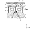
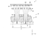
- 22A and 22B show the deposition density in the case where a plurality of limiting plates 320 are provided between the deposition source 301 and the deposition mask 302 along the direction perpendicular to the scanning direction (scanning axis). It is a figure which shows typically the difference in the vapor deposition flow by a difference.
- FIG. 22A shows a case where the deposition density is relatively low (at a low rate), and FIG. 22B shows a case where the deposition density is relatively high (at a high rate).
- the Y axis indicates a horizontal axis along the scanning direction of the film formation substrate 200, and the X axis is perpendicular to the scanning direction of the film formation substrate 200.
- the Z axis is the normal direction of the deposition surface 201 (deposition surface) of the deposition substrate 200, and the direction in which the deposition axis perpendicular to the deposition surface 201 extends is shown.
- a vertical axis (vertical axis) perpendicular to the X axis and the Y axis is shown.
- the vapor deposition particles 401 (vapor deposition flow) passing through the upper opening edge 320a of the limiting plate 320 are cut at the non-opening portion of the vapor deposition mask 302 at a low rate, as indicated by a cross in FIG. .
- the degree of collision / scattering between the vapor deposition particles 401 increases near the upper opening edge 320 a of the limiting plate 320, and the vapor deposition flow restricted by the limiting plate 320. However, it spreads at the moment when it passes through the opening 321 of the limiting plate 320. A part of the spread deposition flow enters the adjacent film formation region on the film formation substrate 200 by the adjacent nozzle 301a.
- vapor deposition particles 401 from adjacent nozzles are mixed into the normal pattern film, or abnormal film formation is formed between the normal pattern films, such as forming an abnormal pattern film that is not formed at a low rate.
- These phenomena cause abnormal light emission such as mixed color light emission, and there is a concern that display quality is greatly impaired.
- the present invention has been made in view of the above problems, and an object thereof is to provide a limiting plate unit, a vapor deposition unit, and a vapor deposition apparatus that can prevent the occurrence of abnormal film formation.
- a vapor deposition unit is provided between a vapor deposition mask, a vapor deposition source that ejects vapor deposition particles toward the vapor deposition mask, and the vapor deposition mask and the vapor deposition source.
- a limiting plate unit that limits the passage angle of the vapor deposition particles emitted from the vapor deposition source, and the limiting plate unit includes a plurality of first limiting plates that are provided apart from each other in the first direction. And at least a plurality of second restriction plates provided on the first restriction plate in plan view and spaced apart from each other in the first direction and along the first restriction plate.
- a plurality of limiting plates are provided, and at least two second limiting plates are provided in the first direction for each first limiting plate.
- a vapor deposition unit is provided between a vapor deposition mask, a vapor deposition source that ejects vapor deposition particles toward the vapor deposition mask, and the vapor deposition mask and the vapor deposition source.
- a limiting plate unit that limits the passage angle of the vapor deposition particles emitted from the vapor deposition source.
- the limiting plate unit includes a plurality of first limiting plates that are spaced apart from each other in the first direction.
- at least two protrusions are provided on the upper surface of the first limiting plate in the first direction along the first limiting plate.
- a vapor deposition apparatus includes the vapor deposition unit according to one aspect of the present invention, a vapor deposition mask in the vapor deposition unit, and a deposition target substrate.
- a moving device that relatively moves one of the vapor deposition unit and the deposition target substrate in a second direction perpendicular to the first direction, and the width of the vapor deposition mask in the second direction is:
- the vapor deposition particles emitted from the vapor deposition source while scanning along the second direction are smaller than the width of the deposition target substrate in the second direction, and the openings of the limiting plate unit and the vapor deposition mask. It is made to vapor-deposit on the said to-be-deposited substrate via.
- a limiting plate unit is provided between a vapor deposition mask and a vapor deposition source, and restricts the passage angle of vapor deposition particles emitted from the vapor deposition source.
- a plurality of first restriction plates provided apart from each other in the first direction, and spaced apart from each other in the first direction on the first restriction plate in plan view; and
- a plurality of second restriction plates provided along the first restriction plate, and a plurality of restriction plates provided at least, wherein the second restriction plate has the first direction in the first direction. At least two sheets are provided for each first limiting plate.
- a limiting plate unit is provided between a vapor deposition mask and a vapor deposition source, and restricts the passage angle of vapor deposition particles emitted from the vapor deposition source.
- a plurality of first restricting plates provided apart from each other in a first direction, and the upper surface of the first restricting plate is arranged along the first restricting plate along the first restricting plate. At least two protrusions are provided in one direction.
- the spread of the flow of vapor deposition particles injected from the vapor deposition source is suppressed by the first limiting plate.
- the vapor deposition component with poor directivity is cut (captured), and is restricted to a distribution with high directivity.
- the controlled deposition flow passes through the opening area between the first restricting plates when the deposition density is high (ie, at high rate) due to collision and scattering between the deposited particles caused by the high deposition density. Later, it tries to spread again, but it is captured by the latter-stage limiting plate including at least the second limiting plate or the above-described protrusion, so that the spread is suppressed, and the state where the spread is suppressed is maintained. pass.
- a 2nd restriction board is arrange
- FIG. (A) * (b) is a perspective view which shows an example of schematic structure of the 2nd restriction board assembly in the restriction board unit concerning Embodiment 1.
- FIG. It is sectional drawing which shows typically schematic structure of the principal part in the vapor deposition apparatus concerning Embodiment 1.
- FIG. 1 shows an example of suitable arrangement
- FIG. (A) * (b) is sectional drawing which shows an example of the arrangement
- FIG. It is sectional drawing which shows an example of schematic structure of the vapor deposition unit 1 concerning the modification 4 of Embodiment 3.
- FIG. 6 is a cross-sectional view showing a schematic configuration of a main part of a vapor deposition unit 1 according to Embodiment 4 together with a film formation substrate 200.
- (A) and (b) schematically show the difference in vapor deposition flow due to the difference in vapor deposition density when a plurality of limiting plates are provided between the vapor deposition source and the vapor deposition mask along the direction perpendicular to the scanning direction.
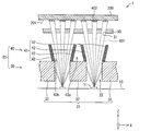
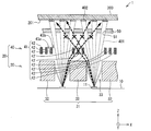
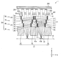
- FIG. 1 is a cross-sectional view showing a schematic configuration of a main part of a vapor deposition unit 1 in a vapor deposition apparatus 100 (see FIG. 5) according to the present embodiment, together with a film formation substrate 200.
- FIG. 2 is a perspective view showing a schematic configuration of the main part of the vapor deposition unit 1 together with the deposition target substrate 200.
- the horizontal axis along the scanning direction (scanning axis) of the film formation substrate 200 is defined as the Y axis
- the horizontal axis along the direction perpendicular to the scanning direction of the film formation substrate 200 is defined as the X axis.
- the vertical direction perpendicular to the X-axis and the Y-axis is the normal direction of the deposition surface 201 (deposition surface) of the deposition substrate 200 and the direction in which the deposition axis perpendicular to the deposition surface 201 extends.
- the axis (vertical axis) will be described as the Z axis.
- the side of the arrow in the Z-axis direction (the upper side of the sheet of FIG. 1) will be described as “upper side”.
- the vapor deposition unit 1 includes a vapor deposition source 10, a vapor deposition mask 50, and a limiting plate unit 20 provided between the vapor deposition source 10 and the vapor deposition mask 50. I have.
- the restriction plate unit 20 includes a plurality of restriction plates, and a restriction plate assembly is formed by each restriction plate. That is, the limiting plate unit 20 includes a plurality of limiting plate assemblies arranged in the Z-axis direction. In this embodiment, as shown in FIGS. 1 and 2, the limiting plate unit 20 includes two limiting plate assemblies, a first limiting plate assembly 30 and a second limiting plate assembly 40.
- the vapor deposition source 10, the first limiting plate assembly 30, the second limiting plate assembly 40, and the vapor deposition mask 50 have, for example, a certain gap from each other in this order along the Z-axis direction from the vapor deposition source 10 side (that is, , Spaced apart by a certain distance).
- the vapor deposition apparatus 100 is a vapor deposition apparatus using a scan vapor deposition method. For this reason, in the vapor deposition apparatus 100, at least one of the deposition target substrate 200 and the deposition unit 1 is relatively moved (scanned) in a state where a certain gap is provided between the deposition mask 50 and the deposition target substrate 200.
- the relative positions of the vapor deposition source 10, the first limiting plate assembly 30, the second limiting plate assembly 40, and the vapor deposition mask 50 are fixed to each other. Therefore, the vapor deposition source 10, the first limiting plate assembly 30, the second limiting plate assembly 40, and the vapor deposition mask 50 are held by a holding member (not shown) such as the same holder such as the holder 60 shown in FIG. It may be hold
- a holding member such as the same holder such as the holder 60 shown in FIG. It may be hold
- the vapor deposition source 10 is, for example, a container that stores a vapor deposition material therein.
- the vapor deposition source 10 may be a container that directly stores the vapor deposition material inside the container, may have a load-lock type pipe, and may be formed so that the vapor deposition material is supplied from the outside.
- the deposition source 10 is formed in a rectangular shape, for example, as shown in FIG. As shown in FIGS. 1 and 2, the vapor deposition source 10 has a plurality of ejection ports 11 (through ports, nozzles) that eject vapor deposition particles 401 onto the upper surface (that is, the surface facing the first restriction plate assembly 30). )have. These injection ports 11 are arranged at a constant pitch in the X-axis direction (first direction, direction perpendicular to the scanning direction).
- the vapor deposition source 10 generates gaseous vapor deposition particles 401 by heating and vaporizing the vapor deposition material (when the vapor deposition material is a liquid material) or sublimating (when the vapor deposition material is a solid material).
- the vapor deposition source 10 injects the vapor deposition material made in this way as vapor deposition particles 401 from the injection port 11 toward the first limiting plate assembly 30.
- one deposition source 10 is provided in the X-axis direction and a plurality of injection ports 11 are provided in one deposition source 10. It is shown.
- the number of vapor deposition sources 10 in the X-axis direction and the number of injection ports 11 provided in one vapor deposition source 10 are not particularly limited.
- a plurality of vapor deposition sources 10 may be arranged in the X axis direction.
- the injection ports 11 may be arranged in a one-dimensional shape (that is, a line shape) in the X-axis direction as shown in FIG. 2, or arranged in a two-dimensional shape (that is, a planar shape (tile shape)). It does not matter.
- the vapor deposition mask 50 is a plate-like object whose mask surface, which is the main surface (surface having the largest area), is parallel to the XY plane.
- a vapor deposition mask having a size at least in the Y-axis direction smaller than that of the deposition target substrate 200 is used as the vapor deposition mask 50.
- the main surface of the vapor deposition mask 50 is provided with a plurality of mask openings 51 (openings, through holes) for allowing vapor deposition particles 401 to pass through during vapor deposition.
- the mask opening 51 is provided corresponding to a partial pattern of the vapor deposition region so that the vapor deposition particles 401 do not adhere to a region other than the target vapor deposition region on the deposition target substrate 200. Only the vapor deposition particles 401 that have passed through the mask opening 51 reach the film formation substrate 200, and the vapor deposition film 402 having a pattern corresponding to the mask opening 51 is formed on the film formation substrate 200.
- the said vapor deposition material is a material of the light emitting layer in an organic electroluminescence display
- vapor deposition of the light emitting layer in an organic EL vapor deposition process is performed for every color of a light emitting layer.
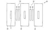
- FIG. 3 is a plan view showing a schematic configuration of a main part of the limiting plate unit 20.
- the limiting plate unit 20 includes a first limiting plate assembly 30 and a second limiting plate assembly 40.
- the first limiting plate assembly 30 includes a first limiting plate row 31 including a plurality of first limiting plates 32 that are spaced apart from each other in the X-axis direction (first direction) and parallel to each other. I have.
- the second limiting plate assembly 40 is provided on the first limiting plate 32 so as to be separated from each other in the X-axis direction (first direction) and parallel to each other along the first limiting plate 32.
- a second restriction plate row 41 including a plurality of second restriction plates 42 is provided.
- the first limiting plate 32 and the second limiting plate 42 each have a YZ plane as a main surface, the main surfaces are adjacent to each other in the X-axis direction, and the main surface of the vapor deposition mask 50 having the XY plane as a main surface. It is arranged so as to be perpendicular to the surface and the deposition surface 201 of the deposition target substrate 200.
- the first limiting plate 32 is parallel to the Y axis in plan view (in other words, when viewed from a direction perpendicular to the main surface of the vapor deposition mask 50, that is, a direction parallel to the Z axis).
- restriction plate openings 33 are formed as opening regions, respectively, in plan view.
- the first restricting plate 32 is arranged such that the injection port 11 of the vapor deposition source 10 is positioned at the center of each restricting plate opening 33 in the X-axis direction. Further, the pitch of the restriction plate openings 33 is formed larger than the pitch of the mask openings 51, and when viewed from the direction perpendicular to the main surface of the vapor deposition mask 50, the first restriction plates 32 adjacent in the X-axis direction. A plurality of mask openings 51 are arranged therebetween.
- At least two second limiting plates 42 are provided on the first limiting plate 32 in the X-axis direction for each first limiting plate 32. 1 to 3 and FIG. 5, the second limiting plate 42 is provided on the first limiting plate 32 along the first limiting plate 32 as a set of two in the X-axis direction. The case is shown as an example.
- the second limiting plates 42 are each extended in parallel to the Y axis in a plan view, and the second limiting plates 42 of each set provided as a set of two pieces have the same pitch.
- a plurality are arranged in parallel to each other in the X-axis direction.
- a limiting plate opening 43b is formed as an opening region between each pair of second limiting plates 42 adjacent in the X-axis direction.
- the pair of second restriction plates 42 provided on the same first restriction plate 32 in plan view are provided apart from each other, and between the pair of second restriction plates 42.
- the limiting plate opening 43a is formed as an opening region.
- the first limiting plate 32 and the second limiting plate 42 are each formed in a rectangular shape, for example.
- the first limiting plate 32 and the second limiting plate 42 are arranged vertically so that the minor axis thereof is parallel to the Z-axis direction. For this reason, the long axis of the first limiting plate 32 and the second limiting plate 42 is arranged in parallel to the Y-axis direction (second direction).
- FIG. 2 shows an example in which the first limiting plate assembly 30 is a block-shaped unit in which limiting plate openings 33 are respectively provided between adjacent first limiting plates 32. .
- FIG. 4A and 4B are perspective views showing an example of a schematic configuration of the second limiting plate assembly 40.
- FIG. 4A and 4B are perspective views showing an example of a schematic configuration of the second limiting plate assembly 40.
- the second limiting plate assembly 40 includes a pair of second limiting plates 42 provided through the limiting plate opening 43a as a set, and each of the adjacent second sets of second limiting plates 42. It may be a block-like unit in which restriction plate openings 43b are respectively provided between the two restriction plates 42, or may have a configuration shown in FIG. 4B, for example.
- the second limiting plate assembly 40 shown in FIG. 4B has a pair of second limiting plates 42 arranged in parallel with the X-axis direction, with the second limiting plates 42 arranged via the limiting plate openings 43a and 43b described above.
- One holding member 44 and a pair of second holding members 45 parallel to the Y-axis direction are integrally held by a method such as welding, for example.
- the first limiting plate assembly 30 is similar to the second limiting plate assembly 40 in that the first limiting plates 32 arranged via the limiting plate openings 33 are each a pair of first parallel plates parallel to the X-axis direction. It has a configuration in which it is integrally held by a method such as welding, for example, on a frame-like holding body similar to the holding body 46, which is configured by a holding member and a pair of second holding members parallel to the Y-axis direction. You may do it.
- each limiting plate may be formed integrally with a holding body that holds (supports) each limiting plate, as shown in FIG. 2 and FIG. 4A, for example. It may be formed separately as shown in FIG.
- the method of holding the first limiting plate 32 and the second limiting plate 42 is as described above. The method is not limited.
- the limiting plate unit 20 divides the space between the vapor deposition mask 50 and the vapor deposition source 10 into a plurality of vapor deposition spaces composed of the limiting plate openings 33 and 43b by the first limiting plate 32 and the second limiting plate 42. By doing so, the passing angle of the vapor deposition particles 401 injected from the vapor deposition source 10 is limited.
- the vapor deposition particles 401 emitted from the vapor deposition source 10 pass through the restriction plate opening 33, pass between the restriction plate openings 43 b, pass through the mask opening 51 formed in the vapor deposition mask 50, and then reach the deposition target substrate 200. Vapor deposited.
- the first limiting plate assembly 30 and the second limiting plate assembly 40 receive the vapor deposition particles 401 incident on the first limiting plate assembly 30 and the second limiting plate assembly 40 as shown in FIG. Cut (capture) selectively according to the angle. That is, the first limiting plate assembly 30 and the second limiting plate assembly 40 capture at least a part of the vapor deposition particles 401 that have collided with the first limiting plate 32 and the second limiting plate 42, thereby The movement of the vapor deposition particles 401 in the arrangement direction of the restriction plate 32 and the second restriction plate 42 (that is, the X-axis direction and the oblique direction) is restricted.
- the first limiting plate assembly 30 and the second limiting plate assembly 40 limit the incident angle of the vapor deposition particles 401 incident on the mask opening 51 of the vapor deposition mask 50 within a certain range and The adhesion of the vapor deposition particles 401 from an oblique direction is prevented.
- the first limiting plate 32 and the second limiting plate 42 are not heated or cooled by a heat exchanger (not shown) in order to cut oblique deposition components. For this reason, the first limiting plate 32 and the second limiting plate 42 are at a temperature lower than the injection port 11 of the vapor deposition source 10 (more strictly, a temperature lower than the vapor generation particle generation temperature at which the vapor deposition material becomes a gas). It has become.
- the first limiting plate assembly 30 includes a cooling mechanism 38 including a heat exchanger or the like that cools the first limiting plate 32 as necessary, as indicated by a two-dot chain line in FIG. May be provided.
- the second limiting plate assembly 40 includes a cooling mechanism 48 including a heat exchanger or the like for cooling the second limiting plate 42 as necessary, as indicated by a two-dot chain line in FIG. May be provided.
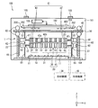
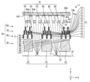
- FIG. 5 is a cross-sectional view schematically showing a schematic configuration of a main part in the vapor deposition apparatus 100 according to the present embodiment.
- FIG. 5 has shown the cross section parallel to the X-axis direction in the vapor deposition apparatus 100 concerning this embodiment.
- the vapor deposition apparatus 100 includes a vacuum chamber 101 (film formation chamber), a substrate holder 102 (substrate holding member), a substrate moving device 103, a vapor deposition unit 1, a vapor deposition unit moving device 104, Alignment observation means such as an image sensor 105, a shutter (not shown), a control circuit (not shown) for driving and controlling the vapor deposition apparatus 100, and the like are provided.
- the substrate holder 102, the substrate moving device 103, the vapor deposition unit 1, and the vapor deposition unit moving device 104 are provided in the vacuum chamber 101.
- the vacuum chamber 101 includes a vacuum pump (not shown) that evacuates the vacuum chamber 101 via an exhaust port (not shown) provided in the vacuum chamber 101 in order to keep the vacuum chamber 101 in a vacuum state during vapor deposition. Is provided.
- the substrate holder 102 is a substrate holding member that holds the deposition target substrate 200.
- the substrate holder 102 holds the deposition target substrate 200 made of a TFT substrate or the like so that the deposition surface 201 faces the deposition mask 50 in the deposition unit 1.
- the deposition target substrate 200 and the vapor deposition mask 50 are opposed to each other with a predetermined distance therebetween, and a gap with a certain height is provided between the deposition target substrate 200 and the vapor deposition mask 50.
- an electrostatic chuck is preferably used for the substrate holder 102. Since the deposition target substrate 200 is fixed to the substrate holder 102 by a technique such as electrostatic chucking, the deposition target substrate 200 is held on the substrate holder 102 without being bent by its own weight.
- scanning is performed by relatively moving the deposition target substrate 200 and the vapor deposition unit 1 so that the Y-axis direction becomes the scanning direction by at least one of the substrate moving device 103 and the vapor deposition unit moving device 104.
- Vapor deposition is performed.
- the substrate moving device 103 includes a motor (not shown), for example, and moves the deposition target substrate 200 held by the substrate holder 102 by driving the motor by a motor drive control unit (not shown).
- the vapor deposition unit moving device 104 includes, for example, a motor (not shown), and drives the motor by a motor drive control unit (not shown), thereby moving the vapor deposition unit 1 relative to the deposition target substrate 200.
- the substrate moving device 103 and the vapor deposition unit moving device 104 drive an unillustrated motor to align the alignment marker 52 provided in the non-opening region of the vapor deposition mask 50 and the non-vapor deposition region in the deposition target substrate 200. Position correction is performed by the provided alignment marker 202 so that the positional deviation between the vapor deposition mask 50 and the deposition target substrate 200 is eliminated.
- the substrate moving device 103 and the vapor deposition unit moving device 104 may be, for example, a roller type moving device or a hydraulic type moving device.
- the substrate moving device 103 and the vapor deposition unit moving device 104 are, for example, a drive unit composed of a motor (XY ⁇ drive motor) such as a stepping motor (pulse motor), a roller, and a gear, and a drive such as a motor drive control unit.
- the film formation substrate 200 or the vapor deposition unit 1 may be moved by providing a control unit and driving the drive unit by the drive control unit.
- the substrate moving device 103 and the vapor deposition unit moving device 104 include a driving unit composed of an XYZ stage or the like, and may be movably provided in any of the X axis direction, the Y axis direction, and the Z axis direction. Good.
- At least one of the deposition target substrate 200 and the vapor deposition unit 1 may be provided so as to be relatively movable.
- at least one of the substrate moving device 103 and the vapor deposition unit moving device 104 may be provided.
- the vapor deposition unit 1 may be fixed to the inner wall of the vacuum chamber 101.
- the substrate holder 102 may be fixed to the inner wall of the vacuum chamber 101.
- the vapor deposition unit 1 includes a vapor deposition source 10, a first limiting plate assembly 30, a second limiting plate assembly 40, a vapor deposition mask 50, a holder 60, a deposition preventing plate 65, a shutter (not shown), and the like. Since the vapor deposition source 10, the first limiting plate assembly 30, the second limiting plate assembly 40, and the vapor deposition mask 50 have already been described, descriptions thereof are omitted here.
- the pair of second restriction plates 42 is in the vicinity of both ends in the X-axis direction of the first restriction plate 32 directly below, specifically, a second restriction plate that forms a pair.
- the edge of the first limit plate 32 on the X-axis direction end portion side of the plate 42 is aligned with the X-axis direction end portion of the first limit plate 32.
- the holder 60 is a holding member that holds the vapor deposition source 10, the first limiting plate assembly 30, the second limiting plate assembly 40, and the vapor deposition mask 50.
- the holder 60 is provided with, for example, a pair of slide devices 61 and a support member 62 in order to support the first limiting plate assembly 30 and the second limiting plate assembly 40, for example.
- the slide device 61 is disposed so as to face both ends of the holder 60 in the X-axis direction. Further, the support member 62 is provided on the facing surface side of each slide device 61. These support members 62 are slidable in the Z-axis direction and the X-axis direction in a state of being opposed to each other, and their movements are controlled by cooperation with the slide device 61 and a limiting plate control device (not shown).
- first limiting plate assembly 30 and the second limiting plate assembly 40 can be detached from the holder 60, and the vapor deposition material deposited on the first limiting plate assembly 30 and the second limiting plate assembly 40 can be removed. It can be collected regularly.
- the vapor deposition material melts or evaporates when heated, and thus can be easily recovered by heat treatment.
- the vapor deposition mask 50 has a high required dimensional accuracy such as its opening width and flatness, and thus may be distorted, and heat treatment cannot be performed.
- the first limiting plate assembly 30 and the second limiting plate assembly 40 do not require the high dimensional accuracy as the vapor deposition mask 50, heat treatment can be performed, and the deposited vapor deposition material can be easily recovered. can do. Accordingly, high material utilization efficiency can be ensured.
- the vapor deposition unit 1 is provided with, for example, a tension mechanism 63 that applies tension to the vapor deposition mask 50 on the holder 60.
- the vapor deposition mask 50 can be held horizontally with tension applied to the vapor deposition mask 50, and the vapor deposition mask 50, the vapor deposition source 10, the first limiting plate assembly 30, and the second limiting plate assembly 40 can be held.
- the relative positional relationship with can be fixed.
- the vapor deposition particles 401 scattered from the vapor deposition source 10 are adjusted so as to be scattered in the vapor deposition mask 50, and the vapor deposition particles scattered outside the vapor deposition mask 50 are attached to the deposition preventing plate 65 (shielding plate). It is good also as a structure removed suitably by these.
- a shutter (not shown) is provided between the vapor deposition source 10 and the first limiting plate assembly 30 in order to control the arrival of the vapor deposition particles 401 to the vapor deposition mask 50. It may be provided so as to be able to advance / retreat (can be inserted / removed) based on an OFF signal or a deposition ON signal.
- vapor deposition in a non-vapor deposition region where vapor deposition is not performed can be prevented.
- the shutter may be provided integrally with the vapor deposition source 10, or may be provided separately from the vapor deposition source 10.
- the vapor deposition flow having an isotropic distribution is suppressed by spreading (capturing) both end sides in the X-axis direction by the first limiting plate 32.
- the vapor deposition flow whose spread is suppressed by the first restriction plate 32 is a restriction that is an opening region between the first restriction plates 32 due to collision / scattering between the vapor deposition particles 401 caused by a high vapor deposition density at a high rate. After passing through the plate opening 33, it spreads again.
- the vapor deposition flow that has spread after passing through the restricting plate opening 33 is cut (captured) by the second restricting plate 42, so that the spreading is suppressed again.
- the vapor deposition flow maintained in a state in which the spread is suppressed by the second limiting plate 42 passes through the mask opening 51 of the vapor deposition mask 50 and is vapor deposited on the deposition target substrate 200.
- the moving device (the substrate moving device 103 and the vapor deposition unit moving device 104) that relatively moves one of the vapor deposition unit 1 and the deposition target substrate 200 in the Y-axis direction that is the scan axis direction.
- the film formation substrate 200 is scanned in the scan axis direction (Y-axis direction), whereby each coating layer (for example, each color light-emitting layer) can be formed.
- Patent Document 1 as a modified example of the limiting plate, a first barrier wall assembly including a plurality of first barrier walls and a second barrier wall including a plurality of second barrier walls between a vapor deposition source and a vapor deposition mask. It is disclosed that the assemblies are arranged so as to correspond to each other (see, for example, FIG. 27 of Patent Document 1).
- Patent Document 1 only one second blocking wall that is the second limiting plate is provided for one first blocking wall that is the first limiting plate. For this reason, the method described in Patent Document 1 cannot completely suppress the spread of the vapor deposition flow spreading on both sides of the first blocking wall. The reason for this will be described below.
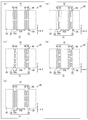
- FIGS. 6A to 6D show, as a comparative example, only one second limiting plate 42 smaller than the first limiting plate 32 is provided for each first limiting plate 32. It is sectional drawing which shows the example.
- FIG. 7 shows, as a comparative example, one second limiting plate 42 having a height from the top of the first limiting plate 32 to the lower end of the vapor deposition mask 50 with respect to one first limiting plate 32. It is sectional drawing which shows the example which provided only.
- the second restriction plate 42 When only one second restriction plate 42 is provided for one first restriction plate 32, the second restriction plate 42 is placed at the center of the first restriction plate 32 as in Patent Document 1.
- the second restriction plate 42 When provided close to one limiting plate 32, as shown in FIG. 6A, at the high rate, the spread of the vapor deposition flow after passing through the first limiting plate 32 on both sides in the X-axis direction is suppressed. I can't.
- the first limiting plate 32 when the second limiting plate 42 is disposed on one end side in the X-axis direction of the first limiting plate 32, the first limiting plate 32 is at the high rate. The spread of the vapor deposition flow on the other end side in the X-axis direction of the plate 32 cannot be suppressed.
- the second limiting plate 42 is adjacent to the limiting plate opening 33 as shown in FIG.
- the mask opening 51 of the vapor deposition mask 50 corresponding to the position where the vapor deposition flows that have passed through, that is, both ends in the X-axis direction of the first restricting plate 32 and the vapor deposition region (adjacent film formation region) by the adjacent injection ports 11 are present. It is desirable to install in the area where the line connecting
- the first restriction plate 32 is used as shown in FIG.
- the second limiting plate 42 having to be installed must be installed.
- the second limiting plate 42 having a large volume as shown in FIG. 7 when the second limiting plate 42 having a large volume as shown in FIG. 7 is provided, the space volume in which the vapor deposition particles 401 are scattered is reduced and the pressure is increased. As a result, the collision / scattering probability between the vapor deposition particles 401 is increased.
- the spatial volume distribution is not changed in the Z-axis direction, and the second restricting plate 42 is raised to the vicinity of the vapor deposition mask 50, so that the vapor deposition particles 401 are in the second restriction plate 42. It is in a state of being confined in the area surrounded by. For this reason, the interparticle scattering of the vapor deposition particles 401 becomes very strong.
- the vapor deposition flow is restricted by the first restriction plate 32 and the vapor deposition flow has directivity, the vapor deposition flow is isotropic again by passing between the second restriction plates 42. Distribution.
- the film formation pattern spreads at the place where the film should be originally formed, causing pattern blur between the film formation areas, increasing the blur width of the vapor deposition film 402, color mixing in adjacent pixels, and the vapor deposition particles 401 in the adjacent nozzle area. This causes problems such as intrusion and non-uniform light emission due to non-uniform film thickness within the pixel.
- At least two second limiting plates 42 are required in the X-axis direction with respect to one first limiting plate 32.
- the first limiting plate 32 and the second limiting plate 42 are installed so as to be parallel on the same YZ plane.
- the second limiting plate 42 is paired with the first limiting plate 32, and the second limiting plate 42 is configured by at least two or more in the X-axis direction with respect to one first limiting plate 32. Paired.
- the first limiting plate 32 and the second limiting plate 42 are arranged in this way, and the second limiting plate 42 is arranged in the X-axis direction for each first limiting plate 32. At least two sheets are provided. For this reason, the spread of the vapor deposition flow spreading on both sides in the X-axis direction can be completely suppressed, and the vapor deposition flow that has spread after passing through the restriction plate opening 33 of the first restriction plate 32 is efficiently generated by the second restriction plate 42. It can capture well and can prevent abnormal film formation such as an abnormal pattern film.
- the vapor deposition flow that has spread after passing through the first restriction plate 32 is cut (captured) by the second restriction plate 42, and the state in which the spread is suppressed is maintained and the vapor deposition mask 50 is maintained.
- the film is deposited on the deposition target substrate 200 through the mask opening 51. Therefore, according to the present embodiment, it is possible to prevent abnormal film formation such as vapor deposition particles 401 from adjacent nozzles being mixed into the normal pattern film or forming an abnormal pattern film between the normal pattern films. Can do.
- the second restriction plate 42 is disposed on the first restriction plate 32 in plan view. That is, the second limiting plate 42 is arranged in a narrower range than the first limiting plate 32. For this reason, according to the present embodiment, the second restricting plate 42 does not exist directly above the restricting plate opening 33, so that only the component whose directivity is truly degraded can be efficiently obtained without reducing the deposition rate at all. Can be captured.
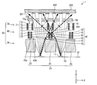
- FIG. 8 is a cross-sectional view of the main part of the vapor deposition unit 1 according to the present embodiment, showing an example of a suitable arrangement of the second restriction plate 42. 8 also shows a schematic configuration of the main part of the vapor deposition unit 1 together with the deposition target substrate 200, as in FIG.
- the vicinity of the upper opening of the first limiting plate 32 (that is, the vicinity of the upper portion of the limiting plate opening 33) has a high vapor deposition density, the interparticle scattering of the vapor deposition particles 401 increases, and the vapor deposition flow tends to spread.
- the paired second limiting plates 42 provided on the same first limiting plate 32 in plan view should be provided as far apart as possible. Is preferred.
- the paired second limiting plates 42 are positioned in the vicinity of both ends in the X-axis direction of the first limiting plate 32 directly below the paired second limiting plates 42.
- the pair of second limiting plates 42 is formed at least at a position in contact with at least a part of both end portions in the X-axis direction of the first limiting plate 32 directly below the pair. As shown in FIG.
- the pair of second limiting plates 42 are formed flush with both ends in the X-axis direction of the first limiting plate 32 directly below the first limiting plate 32.
- the vapor deposition flow spreading on both ends in the X-axis direction on the plate 32 can be captured efficiently. For this reason, the spread of the vapor deposition flow to the X-axis direction both ends of the first limiting plate 32 can be more effectively suppressed.
- the end of the first limiting plate 32 in the X-axis direction (as shown in FIG. An opening edge) and an end portion in the X-axis direction of the second limiting plate 42 (more specifically, in the X-axis direction end portion side of each first limiting plate 32 in the paired second limiting plate 42).
- the second limiting plate 42 that makes a pair is formed at a position that contacts at least a part of both ends in the X-axis direction of the first limiting plate 32 just below the first limiting plate 32. do not have to.
- the second limiting plate 42 is used. This edge may be formed so as to be separated from the opening edge of the first limiting plate 32 to such an extent that the vapor deposition flow at the opening edge of the first limiting plate 32 can be used.
- the first limiting plate 32 only determines which region of the vapor deposition flow emitted from the injection port 11 is used. It is the thickest and becomes thinner toward the end (nozzle end) of the injection port 11.
- the mask opening 51 uses a flat region of the vapor deposition distribution, and the portion where the nozzle end is thin is shielded by the vapor deposition mask 50 without providing the mask opening 51.
- the film thickness distribution at the nozzle center and the nozzle end can be offset. That is, depending on the mask design, the vapor deposition flow at the opening edge of the first limiting plate 32 can be effectively used.
- the vapor deposition area assigned to one nozzle is variable by the first limiting plate 32.
- the entire surface of the panel (film formation substrate 200) cannot be deposited by a single scan, and it is necessary to scan again by shifting the nozzles. In such a case, variations between nozzles and before and after the nozzles are shifted (for example, variations in thermal history) are reflected in the deposited film, and are easily recognized as deposition unevenness.
- the second limiting plate 42 shown in FIG. 8 has the same shape as the first limiting plate 32 extended in the Z-axis direction.
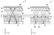
- the vapor deposition particles 401 in the case where the second restriction plate 42 shown in FIG. 8 is provided and in the case where the first restriction plate 32 is extended in the Z-axis direction to the same height as the second restriction plate 42. The difference in flow will be described.
- FIG. 9 shows the vapor deposition unit 1 when the second restriction plate 42 shown in FIG. 8 is provided, and the first restriction plate 32 without the second restriction plate 42 and the same height as the second restriction plate 42. It is sectional drawing which shows and arrange
- the right vapor deposition unit 1 (right diagram) is provided with the second restriction plate 42 shown in FIG. 8, and the left vapor deposition unit 1 (left diagram) is the first restriction plate.
- a dotted frame region A indicates a region where the second limiting plate 42 is provided
- a dotted frame region B indicates The area
- the ratio of the first limiting plate 32 extending in the Z-axis direction of the left diagram or the second limiting plate 42 of the right diagram is larger in the former (left diagram).
- the pressure difference at the boundary between the dotted line frame area A and the dotted line frame area B is the left figure in which the first restriction plate 32 is extended in the Z-axis direction, rather than the right figure in which the second restriction plate 42 is provided. It can be seen that is larger.
- the vapor deposition unit 401 shown in the left figure spreads in the dotted frame region B due to the difference in pressure described above. While the film formation pattern spreads, in the vapor deposition unit 1 shown in the right figure, the spread of the vapor deposition flow can be suppressed and abnormal film formation can be prevented.
- first limiting plate 32 and the second limiting plate 42 are preferably provided as close as possible, and most preferably provided in contact with each other.
- the heights of the first limiting plate 32 and the second limiting plate 42 may be set as appropriate according to the distance between the injection port 11 and the vapor deposition mask 50, and are not particularly limited.
- the deposition flow is confined as shown in FIG.
- the height of the second restriction plate 42 is too low, the ability to cut the spread vapor deposition flow may be insufficient.
- the distance between the second limiting plate 42 and the vapor deposition mask 50 is not particularly specified, but the second limiting plate 42 and the vapor deposition mask 50 are in close contact with each other or the distance is too narrow. Then, when the cooling mechanism is not provided in the second limiting plate 42, heat is transmitted to the vapor deposition mask 50 through the second limiting plate 42, and the vapor deposition mask 50 may be bent by the heat. Further, even if the cooling mechanism is provided in the second limiting plate 42, the vapor deposition mask 50 may be bent by the radiant heat from the vapor deposition source 10, and in that case, the vapor deposition mask 50 is damaged due to contact with the second limiting plate 42. There is a risk.
- the second limiting plate 42 and the vapor deposition mask 50 are appropriately separated from each other, and the first limiting plate 32 and the vapor deposition mask 50 are separated so that the second limiting plate 42 and the vapor deposition mask 50 are separated from each other. It is preferable that the height and arrangement of the second limiting plate 42 are determined.
- the second restriction plate 42 occupies the space between the first restriction plate 32 and the vapor deposition mask 50 so that the vapor deposition flow that has passed through the restriction plate opening 33 does not change the vapor deposition distribution due to a rapid pressure change. A smaller volume is preferable. For this reason, it is preferable that the heights of the first limiting plate 32 and the second limiting plate 42 are determined in consideration of this point.
- FIG. 10 is a cross-sectional view showing a schematic configuration of a main part of a vapor deposition unit according to this modification, together with a film formation substrate.
- the second restriction plate 42 is provided on the first restriction plate 32 so that the opening width between the paired second restriction plates 42 becomes smaller toward the upper side.
- the pair of second limiting plates 42 provided on the first limiting plate 32 is formed in an inverted V shape (that is, a “C” shape) having an opening at the center. Two limiting plates 42 are arranged.
- the second limiting plate 42 is provided in contact with the first limiting plate 32 for the reason described above. Further, in the pair of second limiting plates 42, the edge on the X-axis direction end portion side of each first limiting plate 32 is the X-axis direction end portion (first limiting plate 32) of the first limiting plate 32. It is preferable that the second restricting plate 42 is provided so as to be positioned at the opening edge of the restricting plate opening 33 at 32.
- the spatial volume can be changed in the Z-axis direction as shown in FIG. Specifically, the space on the restriction plate opening 33 between the first restriction plates 32 (specifically, the space in the restriction plate opening 43b between the second restriction plates 42) as it is on the vapor deposition mask 50 side. The volume is increased.
- the present modification it is not necessary to increase the height of the second restricting plate 42 to the vicinity of the vapor deposition mask 50 as shown in FIG. 7, and the restricting plate opening between the first restricting plates 32 is increased upward. Since the spatial volume on 33 spreads, scattering of vapor deposition particles 401 can be suppressed. For this reason, the problem seen in FIG. 7 can be solved, and the vapor deposition flow that has spread after passing through the restriction plate openings 33 between the first restriction plates 32 can be captured more effectively.
- FIGS. 11A to 11E are plan views showing pattern examples of the second restriction plate 42 in the main part of the restriction plate unit 20 according to this modification.
- the second limiting plate 42 has the same length as the length of the first limiting plate 32 in the Y-axis direction on the first limiting plate 32 in plan view, and is continuous in the Y-axis direction.
- the case where it is provided is shown as an example.
- the second limiting plate 42 is shorter than the length of the first limiting plate 32 in the Y-axis direction, and the first limiting plate 32 in plan view.
- a plurality of second limiting plates 42 may be provided intermittently (discontinuously) in the Y-axis direction.
- the second limiting plate 42 (for example, the second limiting plate 42 adjacent in the X-axis direction) at each position in the X-axis direction is not used. There is no need to match continuous locations (regions between opposing ends of the second limiting plates 42 adjacent in the Y-axis direction) at a specific position (specific Y coordinate) in the Y-axis direction. There is no need to match the length.
- the vapor deposition particles 401 do not pass through the discontinuous portions and reach the adjacent film formation region (adjacent mask opening region).
- the X axis is in any position (coordinates) in the Y axis direction.
- at least one second limiting plate 42 exists (that is, there is no Y coordinate position where the second limiting plate 42 does not exist when viewed from a direction parallel to the X-axis direction). It is preferable.
- At least one second limiting plate 42 is present in the region where the paired second limiting plates 42 are formed as viewed from the direction parallel to the X-axis direction at any position in the Y-axis direction. Since it is sufficient to arrange the second limiting plates 42 so as to exist, it is not necessary to match the extending distance in the Y-axis direction of the second limiting plate 42 in the region. Further, it is not necessary for the first limit plate 32 and the second limit plate 42 to have the same length in the Y-axis direction.
- the pair of second limiting plates 42 adjacent to each other in the X-axis direction are respectively opposite end portions in the X-axis direction of the first limiting plate 32 directly below the paired second limiting plates 42.
- the case where it is provided at a position separated from the case is shown as an example.
- the pair of second limiting plates 42 adjacent to each other in the X-axis direction is at least a part thereof (for example, at least the second limiting plate 42 adjacent to the injection port 11 in plan view).
- the first restricting plate 32 directly below is formed at a position in contact with at least a part of both ends in the X-axis direction.
- FIG. 12 is a plan view showing a pattern example of the second restriction plate 42 in the main part of the restriction plate unit 20 according to this modification, together with the injection port 11.
- the vapor deposition distribution of the vapor deposition film 402 is thickest immediately above the injection port 11 (nozzle) and becomes thinner toward the end (nozzle end) of the injection port 11. For this reason, the vapor deposition density is high above the vicinity of the injection port 11, and the collision / scattering of the vapor deposition particles 401 is large.
- the length and arrangement position of the second limiting plate 42 in the Y-axis direction be determined in consideration of the vapor deposition material and the vapor deposition density (vapor deposition rate).
- the second restricting plate 42 faces the injection port 11 in plan view. It is preferable that they are provided adjacent to each other. In this case, the second restricting plate 42 does not necessarily have to be intermittently formed in the Y-axis direction along the first restricting plate 32, and as shown in FIG. 11 may be provided only at a position adjacent to 11.
- the directivity of the vapor deposition flow tends to be deteriorated.
- the second restricting plate 42 does not necessarily have to be provided at a position far from the injection port 11 in plan view.
- the second restriction plate 42 can be provided only in a necessary portion, so that an inexpensive configuration can be achieved.
- a pair of second limiting plates 42 is illustrated as an example in a case where the second limiting plates 42 are provided at positions separated from both ends in the X-axis direction of the first limiting plate 32 immediately below the pair. ing.
- the paired second limiting plates 42 are in contact with both end portions in the X-axis direction (that is, part of both end portions in the X-axis direction) of the first limiting plate 32 immediately below the pair. It is preferably formed at a position (more specifically, flush with part of both end portions in the X-axis direction).
- FIG. 13 is a plan view showing a pattern example of the second restriction plate 42 in the main part of the restriction plate unit 20 according to the present modification example, together with the injection port 11.
- FIGS. 3, 11A to 11E, and FIG. 12 the case where the second restricting plate 42 is a rectangular parallelepiped has been described as an example.
- the shape of 42 may not be a rectangular parallelepiped.
- the end in the Y-axis direction of the second limiting plate 42 has a tapered shape in plan view. Also good.
- the volume occupied by the second limiting plate 42 is small so that the distribution of the vapor deposition flow passing through the limiting plate opening 33 between the first limiting plates 32 does not change due to a rapid pressure change. Therefore, by adopting the shape shown in FIG. 13, it is possible to suppress a change in the distribution of the vapor deposition flow that has passed through the limiting plate opening 33 (the vapor deposition distribution of the vapor deposition film 402), and therefore it is possible to perform more accurate control. .
- the pair of second limiting plates 42 are provided at positions separated from both ends in the X-axis direction of the first limiting plate 32 immediately below the pair.
- the pair of second limiting plates 42 is also configured such that the paired second limiting plates 42 have both ends in the X-axis direction (that is, a part of both ends in the X-axis direction) immediately below the first limiting plate 32. ) Is preferably formed at a position in contact with.
- the height (the length in the Z-axis direction) of the second restriction plate 42 may be finely adjusted in order to reduce individual differences between the injection ports 11.
- an abnormality can be caused by providing two second restriction plates 42 in the X-axis direction for one first restriction plate 32. Film formation can be sufficiently suppressed.
- the arrangement position of the second restriction plate 42 is changed. If it is more inside, there may be a case where it is difficult to say that the effect of trapping the vapor deposition particles 401 causing abnormal film formation is insufficient, such as the possibility that the vapor deposition flow outside the arrangement position of the second limiting plate 42 may not be captured. is there.
- the first limiting plate 32 and the second limiting plate 42 are not in close contact, the first limiting plate 32 and the second limiting plate.
- the length of the second limiting plate 42 in the X-axis direction is increased (in other words, the second It is also conceivable to increase the width of the limiting plate 42).
- the width of the second limiting plate 42 increases, the second limiting plate 42 becomes heavy and alignment accuracy cannot be obtained. Further, since the occupied volume of the second limiting plate 42 increases, a rapid pressure change is caused in the vapor deposition flow after passing through the second limiting plate 42. For this reason, it is preferable that the width of the second limiting plate 42 in the X-axis direction is relatively thinner than the width of the first limiting plate 32 in the X-axis direction.
- the width of the second limiting plate 42 in the X-axis direction is relatively thin, the length in the Z-axis direction is relatively long on both ends of the first limiting plate 32 in the X-axis direction.
- the second restriction plate 42 can be provided, abnormal film formation is sufficiently suppressed by providing two second restriction plates 42 in the X-axis direction with respect to one first restriction plate 32. it can.
- the height of the space in which the second restricting plate 42 is installed (that is, the distance between the first restricting plate 32 and the vapor deposition mask 50) cannot be secured sufficiently, and the ratio of the spread of the vapor deposition flow is not sufficient.
- the second limiting plate 42 having a short length in the Z-axis direction can only be used.
- the length of the second restricting plate 42 in the Z-axis direction is increased in order to capture the vapor deposition flow, the space volume in which the vapor deposition particles 401 are scattered is reduced and the pressure is increased. For this reason, even if it is a case where the height of the space where the 2nd limitation board 42 is installed can fully be secured, depending on the magnitude
- FIG. 14 is a cross-sectional view showing a schematic configuration of the main part of the vapor deposition unit 1 according to the present embodiment, together with the film formation substrate 200.
- the vapor deposition unit 1 shown in FIG. 14 is longer in the Z-axis direction than the first limiting plate 32 when the first limiting plate 32 and the second limiting plate 42 are not in close contact with each other. Is the same as the vapor deposition unit 1 shown in the first embodiment except that three second restriction plates 42 shorter than those in the first embodiment are provided.
- the vapor deposition flow that cannot be captured by the second restriction plates 42 provided on both ends of the first restriction plate 32 in the X-axis direction is the first restriction.
- the plate 32 is captured by the second limiting plate 42 provided at the center in the X-axis direction. Therefore, even when a restriction plate having a short length in the Z-axis direction is used for the second restriction plate 42, the abnormal film formation can be sufficiently suppressed.
- three second restriction plates 42 are provided for one first restriction plate 32, particularly, as shown in FIG. 14, the first restriction plate 32. And the second restriction plate 42 are not in close contact with each other, by providing three second restriction plates 42 for one first restriction plate 32, without lowering the alignment accuracy, Without causing a sudden pressure change after the vapor deposition flow passes through the first restricting plate 32, the vapor deposition flow that spreads extremely large (the vapor deposition flow that spreads by sewing the gap between the first restricting plate 32 and the second restricting plate 42). ) Can also be captured.
- FIG. 14 shows an example in which three second restriction plates 42 are provided for each first restriction plate 32
- the present embodiment is not limited to this.
- Three or more second restriction plates 42 may be provided for each first restriction plate 32 according to the spread of the vapor deposition flow.
- the number of the second restriction plates 42 per one first restriction plate 32 is excessively increased, alignment for obtaining a high-definition pattern becomes complicated, and the occupied volume of the second restriction plate 42 is increased. Is also not preferable.
- first limiting plate 32 and the second limiting plate 42 are not in close contact with each other is illustrated as an example, but the present embodiment is not limited to this, and the first limiting plate 32 and the second limiting plate 42 are not limited thereto.
- the limiting plate 32 and the second limiting plate 42 may be in close contact with each other.
- the second restriction plates 42 provided on both ends of the first restriction plate 32 in the X-axis direction protrude in the Z-axis direction.
- the first limiting plate 32 is provided by providing the second limiting plate 42 (for example, the second limiting plate 42 having a longer length in the Z-axis direction than the second limiting plate 42 on both ends in the X-axis direction).
- the vapor deposition flow that cannot be captured by the second restricting plate 42 provided on both ends in the X-axis direction is It can be captured by the second limiting plate 42 provided between the second limiting plates 42 provided on the side.
- the number of the second limiting plates 42 provided between the second limiting plates 42 provided on both ends in the X-axis direction is not particularly limited. Even if only one second limiting plate 42 is provided at the center in the X-axis direction of the first limiting plate 32 between the second limiting plates 42 provided on both ends in the X-axis direction. Alternatively, two or more sheets may be provided apart from each other.
- the height of the second limiting plate 42 provided between the second limiting plates 42 provided on both ends in the X-axis direction is, for example, in accordance with the vapor deposition material used, the vapor deposition rate, etc. What is necessary is just to set suitably in the range by which the raise of the pressure by the reduction
- the modified example of the second limiting plate 42 can reflect the idea shown in the first embodiment.
- the number of the second limiting plates 42 on the same YZ plane, which is located on the same first limiting plate 32 in plan view (the number of the second limiting plates 42 per first limiting plate 42).
- the case where the vapor deposition particles 401 spreading after passing through the restriction plate opening 33 between the first restriction plates 32 is cut (captured) has been described as an example when the spread of the vapor deposition flow is large by increasing the number.
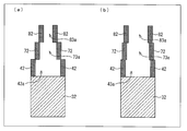
- FIG. 16 is a cross-sectional view showing a schematic configuration of the vapor deposition unit 1 in which the second restriction plate assembly 40 and the third restriction plate assembly 70 are provided between the first restriction plate assembly 30 and the vapor deposition mask 50. .
- the third limiting plate assembly 70 is provided on the first limiting plate 32 so as to be separated from each other in the X-axis direction and parallel to each other along the first limiting plate 32.
- a third limiting plate row 71 including a plurality of third limiting plates 72 is provided.
- the third limiting plate 72 has a YZ plane as a main surface, each main surface is adjacent to the X-axis direction, and the main surface of the vapor deposition mask 50 having the XY plane as a main surface. In addition, they are arranged so as to be perpendicular to the deposition surface 201 of the deposition target substrate 200.
- the third limiting plate 72 is a pair of two in the X-axis direction along the first limiting plate 32 on the first limiting plate 32, like the second limiting plate 42.
- the case where it is provided is shown as an example.
- each set of third restriction plates 72 provided in pairs in the X axis direction includes: A plurality of them are arranged in parallel with each other in the X-axis direction at the same pitch.
- a restriction plate opening 73b is formed as an opening region between each pair of third restriction plates 72 adjacent in the X-axis direction.
- the paired third restriction plates 72 provided on the same first restriction plate 32 in plan view are provided apart from each other, and between the paired third restriction plates 72.
- the limiting plate opening 73a is formed as an opening region.
- the third restriction plates 72 are each formed in a rectangular shape, for example.
- the third limiting plates 72 are arranged vertically so that the minor axis thereof is parallel to the Z-axis direction. For this reason, the long axis of the third limiting plate 72 is arranged parallel to the Y-axis direction.
- the third restriction plate assembly 70 includes a pair of third restriction plates 72 provided through a restriction plate opening 73a as a set. It may be a block-shaped unit in which a limiting plate opening 73b is provided between each pair of adjacent third limiting plates 72.
- the third limiting plate assembly 70 includes, for example, the third limiting plate 72 arranged via the limiting plate openings 73a and 73b described above, like the second limiting plate assembly 40 shown in FIG.
- a frame-like holding body similar to the holding body 46 which includes a pair of first holding members parallel to the X-axis direction and a pair of second holding members parallel to the Y-axis direction, for example, welding or the like You may have the structure hold
- the method of holding the third restriction plate 72 is not limited to the above method.
- the third limiting plate assembly 70 divides a space between the second limiting plate assembly 40 and the vapor deposition mask 50 into a plurality of vapor deposition spaces including the limiting plate openings 73b by the third limiting plate 72.
- the passage angle of the vapor deposition particles 401 that have passed through the restriction plate opening 43b between the second restriction plates 42 is restricted.
- the first limiting plate assembly 30, the second limiting plate assembly 40, and the third limiting plate assembly 70 are provided separately from each other in this order from the vapor deposition source 10 side.
- Each of the first limiting plates 32 uses two second limiting plates 42 and three third limiting plates 72 in the X-axis direction.
- the second limiting plates 42 are respectively arranged closer to the center of the first limiting plate 32 in the X-axis direction.
- the second restricting plate 42 is disposed closer to the center of the first restricting plate 32 in the X-axis direction, so that the vapor deposition flow that passes outside the installation position of the second restricting plate 42 (for example, the second restricting plate 42).
- the third restricting plate 72 is placed so that the third restricting plate 72 is positioned on a path (that is, the vapor deposition flow intersecting above the plate 42) (that is, the vapor deposition particle 401 scattering path).
- the first limiting plate 32 is disposed closer to the end in the X-axis direction than the second limiting plate 42.
- the lower second restriction plate row 41 (second restriction plate group 42) captures a relatively wide spread vapor deposition flow
- the upper third restriction plate row 71 captures the vapor deposition flow having a relatively small spread.
- the number of the limiting plates on the same YZ plane can be reduced by functionally separating the trapping range of the vapor deposition particles 401 with the limiting plates of the respective stages in accordance with the extent of the vapor deposition flow.
- a widened deposition flow can be captured without an increase.
- an increase in the occupied volume of the second restriction plate 42 due to an increase in the number of the second restriction plates 42 occupying the same YZ plane can be suppressed.
- the second restricting plate 42 can be accurately arranged with respect to the spread of any vapor deposition flow, the pressure change after passing through the restricting plate opening 33 can be suppressed, and abnormal The film can be effectively prevented.
- the second restriction plate assembly 40 includes a multi-stage restriction plate. It does not matter as a configuration. That is, for example, the lower second restriction plate 42 and the upper third restriction plate 72 may be held by one holding body, and the second restriction plate assembly 40 may be the second restriction plate. 42 and the third limiting plate 72 may be provided.
- the number of sheets in the X-axis direction per one first limiting plate 32 in the limiting plates at each stage provided on the first limiting plate 32 is not limited to two, and may be one. And 3 or more may be sufficient.
- the number of limiting plates in each step per one limiting plate per first limiting plate 32 may be the same or different.
- FIG. 17 is a cross-sectional view showing an example of a schematic configuration of the vapor deposition unit 1 according to this modification.
- a single first limiting plate 32 is provided with two second limiting plates 42 and one third limiting plate 72 in the X-axis direction. It is shown.
- a vapor deposition flow that spreads greatly after passing through the restriction plate openings 33 between the first restriction plates 32 (for example, the second restriction plate 42 is arranged on the X-axis direction end side of the first restriction plate 32).
- the second restriction plate 42 is disposed near the center of the first restriction plate 32 in the X-axis direction in order to capture the vapor deposition flow that is wider than the arrangement of the second restriction plate 42.
- the third restriction plate 72 is positioned above the second restriction plate 42 (deposition) so that the third restriction plate 72 is positioned on the vapor deposition flow path that passes outside the installation position of the second restriction plate 42.
- Two third restricting plates 72 are provided in the X-axis direction above the intersecting portion of the vapor deposition flows intersecting on the mask 50 side), but the first restricting plate 32 is formed on one first restricting plate 32 as shown in FIG.
- the third limiting plate 72 is disposed at the intersection as shown in FIG.
- the third limiting plate 72 is adjacent to the X-axis direction. Between the three limiting plates 72, limiting plate openings 73 are provided as opening regions, respectively.
- the third limiting plate assembly 70 divides the space between the second limiting plate assembly 40 and the vapor deposition mask 50 into a plurality of vapor deposition spaces including the limiting plate openings 73 by the third limiting plate 72.
- the passage angle of the vapor deposition particles 401 that have passed through the restriction plate opening 43b between the second restriction plates 42 is restricted.
- FIGS. 16 and 17 a case where two stages of limiting plates are provided between the first limiting plate assembly 30 and the vapor deposition mask 50 is shown as an example.
- the limiting plate between the vapor deposition mask 50 may be composed of three or more stages. In other words, three or more limiting plate assemblies may be provided between the first limiting plate assembly 30 and the vapor deposition mask 50.
- the vapor deposition unit 1 includes a plurality of limiting plate assemblies in the Z-axis direction, and each limiting plate assembly includes a plurality of limiting plates, so that it is easy for any substrate size, pattern size, material, etc. It can correspond to.
- a limiter plate may be further provided in the Z-axis direction in order to capture the vapor deposition rate that spreads after passing through the limiter plate opening 43b depending on the deposition rate.
- FIG. 18 is a cross-sectional view showing an example of a schematic configuration of the vapor deposition unit 1 according to this modification.
- FIGS. 19A and 19B are cross-sectional views showing an example of the arrangement method of the limiting plates at each stage according to the present modification.
- a fourth limiting plate assembly 80 is provided between the third limiting plate assembly 70 and the vapor deposition mask 50.
- the schematic configuration of the fourth limiting plate assembly 80 is the same as that of the third limiting plate assembly 70 except that the fourth limiting plate assembly 80 is provided between the third limiting plate assembly 70 and the vapor deposition mask 50. Therefore, as shown in FIG. 18, the fourth limiting plate assembly 80 is provided on the first limiting plate 32 so as to be spaced apart from each other in the X-axis direction and parallel to each other along the first limiting plate 32. And a fourth limiting plate row 81 including a plurality of fourth limiting plates 82.
- the fourth limiting plate 82 has a YZ plane as a main surface, each main surface is adjacent to the X-axis direction, and the main surface of the vapor deposition mask 50 having the XY plane as a main surface. In addition, they are arranged so as to be perpendicular to the deposition surface 201 of the deposition target substrate 200.
- the fourth restriction plate 82 is a set of two on the first restriction plate 32 along the first restriction plate 32 in the X-axis direction. The case where it is provided is shown as an example.
- the fourth limiting plate 82 extends in parallel to the Y axis in a plan view, and each set of the fourth limiting plate 82 provided in a pair in the X axis direction includes: A plurality of them are arranged in parallel with each other in the X-axis direction at the same pitch. As a result, a limiting plate opening 83b is formed as an opening region between each pair of fourth limiting plates 82 adjacent in the X-axis direction.
- paired fourth limiting plates 82 provided on the same first limiting plate 32 in plan view are provided apart from each other, and between the paired fourth limiting plates 82.
- a limiting plate opening 83a is formed as an opening region.
- the fourth restriction plates 82 are each formed in a rectangular shape, for example.
- Each of the fourth limiting plates 82 is arranged vertically so that the minor axis thereof is parallel to the Z-axis direction. For this reason, the long axis of the fourth limiting plate 82 is arranged parallel to the Y-axis direction.
- the fourth restriction plate 82 can be held by a method similar to the method for holding the third restriction plate 72.
- the holding method of the fourth limiting plate 82 is not particularly limited as long as the relative position and posture of the fourth limiting plate 82 can be maintained constant. Absent.
- the fourth limiting plate assembly 80 divides the space between the third limiting plate assembly 70 and the vapor deposition mask 50 into a plurality of vapor deposition spaces each including the limiting plate opening 83b by the fourth limiting plate 82.
- the passage angle of the vapor deposition particles 401 that have passed through the restriction plate opening 73b between the third restriction plates 72 is restricted.
- the second restriction that makes a pair with the opening edge of the restriction plate opening 33 in the first restriction plate 32. It is preferable that at least a part of the plate 42 is in contact with the edge of each first limiting plate 32 on the end side in the X-axis direction.
- the restriction plates when the restriction plates are provided in a multi-stage arrangement in the Z-axis direction, the restriction plates (second restriction plate 42 and third restriction plate 72) formed on the first restriction plate 32 in a plan view.
- the fourth limiting plate 82) are at least partially in contact with each other, and are formed on the adjacent first limiting plates 32, and are opposed to each other in the same plane (second limiting plate). It is preferable that the distance between the plate 42, the third limiting plate 72, and the fourth limiting plate 82) be arranged so as to increase toward the vapor deposition mask 50 side.
- the limiting plate (for example, the second limiting plate 42 and the third limiting plate) formed on the first limiting plate 32 in plan view.
- the opening width between the plate 72 and the fourth limiting plate 82 becomes smaller toward the upper side (that is, an inverted V shape having an opening at the center (that is, a “C” shape)). It is preferable that a limiting plate is provided.
- the vapor deposition flow may leak from the gap.
- the gap between the limiting plates formed on the first limiting plate 32 (for example, the second limiting plate 42, the third limiting plate 72, and the fourth limiting plate 82).
- the spatial volume on the opening region between the first restriction plates 32 (restriction plate openings 33) is increased toward the vapor deposition mask 50 side, which is the scattering direction of the vapor deposition particles 401, scattering of the vapor deposition particles 401 can be suppressed. . For this reason, the vapor deposition flow that has spread after passing through the opening region between the first restriction plates 32 (restriction plate openings 33) can be captured more effectively.
- each of the limiting plates (second limiting plate 42, third limiting plate 72, and fourth limiting plate 82) provided on the first limiting plate 32 is shown in FIG.
- the end surface on the X-axis direction end portion side of the first limiting plate 32 in the upper limiting plate is in the X-axis direction central portion side of the first limiting plate 32 in the lower limiting plate in contact with the limiting plate.
- the adjacent restriction plates, that is, the restriction plates (second restriction plate 42, third restriction plate 72, fourth restriction plate 82) that are in contact with each other partially overlap each other. Is more preferable.
- FIG. 19A when the restricting plates that are in contact with each other are brought into contact with each other only at their edges, it is necessary to precisely align the restricting plates at each stage.
- FIG. 19B there is an advantage that alignment is facilitated by partially overlapping the limiting plates that are in contact with each other.
- an opening between the limiting plates (for example, the second limiting plate 42, the third limiting plate 72, and the fourth limiting plate 82) formed on the first limiting plate 32 in plan view.
- the limiting plates of each step are arranged so that the width becomes smaller toward the upper side, the second limiting plate 42, the third limiting plate 72, and the fourth limiting plate 82 are provided on the first limiting plate 32.
- the same effect can be obtained when only the second restriction plate 42 and the third restriction plate 72 are provided on the first restriction plate 32. It goes without saying that you can get it.
- the second limiting plate 42 is disposed on the first limiting plate 32 so that the paired second limiting plate 42 has an inverted V shape with the center opened.
- the restriction plate can be installed more easily than in this modification.
- FIG. 10 shows that the limiting plate unit 20 includes only the second limiting plate 42 on the first limiting plate, and therefore contamination due to the deposition particles 401 adhering to the second limiting plate 42. It is necessary to replace the entire second restriction plate 42 during replacement for preventing the above.
- by providing a plurality of limiting plates as in this modified example it is only necessary to replace the limiting plate that is very dirty due to the adhesion of the vapor deposition particles 401, and maintenance is good.
- ⁇ Modification 4> As shown in FIGS. 18 and 19A and 19B, the lowermost portion (lower surface) of the second restricting plate 42 and the uppermost portion (upper surface) of the first restricting plate 32 are in contact (adhesion). In this case, it is necessary to increase the number of steps of the limiting plate in the Z-axis direction as the deposition rate increases, but in any case, each step disposed on the first limiting plate in plan view.
- the restriction plate may be a set of two sheets, and this is the most effective installation method.
- FIG. 20 is a cross-sectional view showing an example of a schematic configuration of the vapor deposition unit 1 according to this modification.
- the limiting plates (the second limiting plate 42, the third limiting plate 72, the fourth limiting plate 82) formed on the first limiting plate 32 in plan view.
- the limiting plates (second limiting plate 42, third limiting plate) that are at least partially in contact with each other and are formed on the adjacent first limiting plates 32 and face each other in the same plane.
- 72 and the fourth limiting plate 82) are arranged so as to increase toward the vapor deposition mask 50 side.
- vapor deposition is performed from the gap between the limiting plates formed on the first limiting plate 32 (for example, the second limiting plate 42, the third limiting plate 72, and the fourth limiting plate 82).
- the flow does not leak.
- the spatial volume on the opening region between the first restriction plates 32 (restriction plate openings 33) is increased toward the vapor deposition mask 50 side, which is the scattering direction of the vapor deposition particles 401, scattering of the vapor deposition particles 401 can be suppressed. . For this reason, the vapor deposition flow that has spread after passing through the opening region between the first restriction plates 32 (restriction plate openings 33) can be captured more effectively.
- the fourth restriction plate assembly 80 includes the fourth restriction plate 82 is illustrated as an example.
- the limiting plate 82 may also be held by the same holding body as at least one of the second limiting plate 42 and the third limiting plate 72.
- the second limiting plate assembly 40 may include a second limiting plate 42, a third limiting plate 72, and a fourth limiting plate 82.
- the modification of the third restriction plate 72 can reflect the same idea as the second restriction plate 42 shown in the first and second embodiments. Further, it goes without saying that the same idea as the third restriction plate 72 can be reflected in the modified example of the fourth restriction plate 82.
- FIG. 21 is a cross-sectional view showing a schematic configuration of the main part of the vapor deposition unit 1 according to the present embodiment, together with the film formation substrate 200.
- the upper surface of the first restriction plate 32 is arranged along the first restriction plate 32.
- the second embodiment is the same as the first embodiment except that two protrusions 32a extending in the Z-axis direction are provided in the X-axis direction.
- first limiting plate 32 and the second limiting plate 42 are provided in contact with each other as shown in FIG.
- FIG. 8 As can be seen from a comparison between FIG. 8 and FIG. 21, the same effect as FIG. 8 can be obtained by adopting the configuration shown in FIG. 21.
- the first restricting plate 32 suppresses the spread of the flow (vapor deposition flow) of the vapor deposition particles 401 injected from the vapor deposition source 10. Thereby, the vapor deposition particles 401 with poor directivity are cut (captured), and the distribution is controlled to have high directivity.
- the controlled deposition flow has an opening area between the first limiting plates 32 due to collision / scattering between the deposition particles 401 caused by the high deposition density.
- the protrusion 32a is formed on the upper surface of the first restricting plate 32, the directivity becomes worse without reducing the vapor deposition rate at all, unlike the case where the restricting plate is provided immediately above the restricting plate opening 33. It is possible to efficiently capture only the components.
- the limiting plate unit 20 includes only the second limiting plate 42 on the first limiting plate 32, in order to prevent contamination due to the deposition particles 401 adhering to the second limiting plate 42. At the time of replacement, it is only necessary to replace the restricting plate which is very dirty due to the adhesion of the vapor deposition particles 401, and there is an advantage that the maintainability is good. On the other hand, according to the present embodiment, there is an advantage that it is possible to save the labor of alignment when arranging the second limiting plate 42 on the first limiting plate 32 and it is easy to install the limiting plate.
- the method of providing the projection part 32a in the 1st restriction board 32 is not specifically limited, Well-known methods, such as mold shaping
- the first limiting plate can be provided also when the protrusion 32a is provided on the upper surface of the first limiting plate 32 instead of providing the second limiting plate 42 on the first limiting plate 32.
- the protrusion 32 a corresponding to the second restriction plate 42 has both end portions in the X-axis direction of the first restriction plate 32 (that is, the first restriction plate 42).
- the plate 32 is preferably formed so as to be in contact with (for example, flush with the both end portions) at least a part of both ends in the X-axis direction other than the protrusions 32a.
- the modified example of the projecting portion 32a can reflect the idea regarding the second restriction plate 42 shown in the first and second embodiments.
- the protrusion 32a can be modified in the same manner as the second restriction plate 42 shown in FIGS. 11 (a) to 11 (e). That is, the second limiting plate 42 can be read as the protrusion 32a.
- the case where two protrusions 32 a are provided on the upper surface of the first restriction plate 32 is illustrated as an example, but the protrusion 32 a is formed with respect to one first restriction plate 32. Three or more may be provided.
- the protrusions 32a are provided on the upper surface of the first restriction plate 32, as described in the second embodiment, for example, between the protrusions 32a provided on both ends of the first restriction plate 32 in the X-axis direction.
- the protrusions 32a projecting in the Z-axis direction from the protrusions 32a provided on both ends in the X-axis direction that is, in this case, the length in the Z-axis direction is longer than the protrusions 32a on both ends in the X-axis direction
- the vapor deposition flow that could not be captured by the projecting portions 32a provided on both ends in the X-axis direction is interposed between the projecting portions 32a provided on both ends in the X-axis direction. It can be captured by the provided protrusion 32a.
- the number of protrusions 32a provided between the protrusions 32a provided on both ends in the X-axis direction is not particularly limited. Between the protrusions 32a provided on both ends in the X-axis direction, for example, only one protrusion 32a may be provided in the center of the first limiting plate 32 in the X-axis direction, and two or more may be provided. They may be provided apart from each other.
- the height of the projections 32a provided between the projections 32a provided on both ends in the X-axis direction is improved in capture efficiency depending on, for example, the vapor deposition material and vapor deposition rate used.
- it may be set as appropriate within a range in which the increase in pressure due to the decrease in the space volume in which the vapor deposition particles 401 are scattered does not become too large, and is not particularly limited.
- the vapor deposition unit 1 is provided between the vapor deposition mask 50, the vapor deposition source 10 that ejects the vapor deposition particles 401 toward the vapor deposition mask 50, and the vapor deposition mask 50 and the vapor deposition source 10.
- a limiting plate unit 20 that limits the passage angle of the vapor deposition particles 401 emitted from the vapor deposition source 10, and the limiting plate unit 20 is provided in a plurality spaced apart from each other in the first direction (X-axis direction).
- the first limiting plate 32 and the first limiting plate 32 in plan view are spaced apart from each other in the first direction and provided along the first limiting plate.
- a plurality of limiting plates (for example, the first limiting plate 32, the second limiting plate 42, the third limiting plate 72, and the fourth limiting plate 82).
- the second limiting plate 42 is arranged in the first direction with the first limiting plate 42.
- the flow of the vapor deposition particles 401 ejected from the vapor deposition source 10 (vapor deposition flow) is suppressed from being spread by the first limiting plate 32.
- the vapor deposition particles 401 with poor directivity are cut (captured), and the distribution is controlled to have high directivity.
- the controlled deposition flow has an opening area between the first limiting plates 32 due to collision / scattering between the deposition particles 401 caused by the high deposition density.
- the (restriction plate opening 33) After passing through the (restriction plate opening 33), it tries to spread again, but it includes a second-stage restriction plate (for example, the second restriction plate 42, the third restriction plate 72, the fourth restriction plate) including at least the second restriction plate 42.
- a second-stage restriction plate for example, the second restriction plate 42, the third restriction plate 72, the fourth restriction plate
- the spread is suppressed, and the state in which the spread is suppressed is maintained, and the vapor passes through the vapor deposition mask 50.
- at least two second restriction plates 42 are provided for each first restriction plate (first restriction plate 32). It is possible to effectively capture the vapor deposition flow spreading on both ends in one direction. For this reason, the spread of the vapor deposition flow in the above direction can be effectively suppressed.
- the second limiting plate 42 is disposed on the first limiting plate 32 in a plan view, and the second limiting plate 42 has an opening region (restriction between the first limiting plates). Since it does not exist directly above the plate opening 33), it is possible to efficiently capture only the component whose directivity is really deteriorated without reducing the deposition rate at all.
- the vapor deposition unit 1 according to Aspect 2 of the present invention is the vapor deposition unit 1 according to Aspect 1, wherein the length of the second restriction plate 42 in the second direction (Y-axis direction) perpendicular to the first direction is the second length.
- the second restriction plate 42 is shorter than the length of the first restriction plate 32 in the first direction, and the second restriction plate 42 is on the first restriction plate 32 in a plan view in a second direction perpendicular to the first direction. It is preferable that a plurality are provided intermittently.
- the second limiting plate 42 is provided on the first limiting plate 32 intermittently in the second direction perpendicular to the first direction, so that the second The arrangement of the restriction plate 42 can be finely adjusted, and the replacement work of the second restriction plate 42 is facilitated.
- the vapor deposition unit 1 is the vapor deposition unit 10 in the vapor deposition source 10 between the first restriction plates 32 when viewed from the direction perpendicular to the main surface of the vapor deposition mask 50 in the above aspect 1.
- the ejection port 11 for the vapor deposition particles 401 is provided, and the length of the second restriction plate 42 in the second direction perpendicular to the first direction is the first restriction plate in the second direction.
- the second limiting plate 42 is preferably provided adjacent to the injection port 11 when viewed from a direction shorter than 32 and perpendicular to the main surface of the vapor deposition mask 50.
- the second restriction plate 42 may not necessarily be provided.
- the second restricting plate 42 can be provided only at a necessary location by the above configuration, an inexpensive configuration can be achieved.
- the vapor deposition unit 1 according to Aspect 4 of the present invention is the vapor deposition unit 1 according to Aspect 3, wherein the second limiting plate 42 is an end in the second direction when viewed from a direction perpendicular to the main surface of the vapor deposition mask 50. It is preferable that the part has a tapered shape.
- the volume occupied by the second limiting plate 42 is small so that the distribution of the vapor deposition flow that has passed through the opening region (the limiting plate opening 33) between the first limiting plates 32 does not change due to a rapid pressure change. If it is set as said structure, since the change of the distribution of the vapor deposition flow which passed the opening area
- the vapor deposition unit 1 according to the fifth aspect of the present invention is the vapor deposition unit 1 according to any of the first to fourth aspects, wherein the second restriction plate 42 is at least at both ends of the first restriction plate 32 in the first direction. It is preferably formed at a position in contact with at least a part.
- the second restriction plate 42 is provided in contact with the first restriction plate 32, and at least in the first direction of the first restriction plate 32. It is preferable to be formed at a position that is flush with both ends.
- the vapor deposition density is high, scattering between the vapor deposition particles 401 increases, and the vapor deposition flow tends to spread. For this reason, by setting it as said structure, the vapor deposition flow which spreads to the 1st direction both ends in the 1st restriction board 32 can be caught efficiently, and the spread of the vapor deposition flow to the said 1st direction both ends more It can be effectively suppressed.
- the vapor deposition unit 1 according to aspect 6 of the present invention is the vapor deposition unit 1 according to any one of the aspects 1 to 5, wherein the second restriction plate 42 is arranged in the first direction with the first restriction plate (first restriction plate). 32) It is preferable that three are provided per sheet.
- the dimensional accuracy is not lowered and a rapid pressure change is caused.
- the vapor deposition flow that spreads after passing through the opening region between the first limiting plates 32 (the limiting plate opening 33), or the opening region between the first limiting plates 32. It is also possible to capture the vapor deposition flow that has spread significantly after passing through the (restriction plate opening 33).
- the vapor deposition unit 1 according to the seventh aspect of the present invention is the vapor deposition unit 1 according to any one of the first to sixth aspects, wherein the first limiting plate 32 is positioned above the second limiting plate 42 in the plan view. It is preferable to include at least a plurality of third limiting plates 72 that are spaced apart from each other in the direction of the direction and provided along the first limiting plate 32.
- the second restriction plate 32 with respect to the first restriction plate 32 in the first direction (X-axis direction) is provided. While suppressing an increase in the number of the limiting plates 42, it is possible to capture the vapor deposition flow that has spread after passing through the opening region between the first limiting plates 32 (the limiting plate opening 33).
- the limiting plates (the second limiting plate 42 and the third limiting plate 72) are accurately installed on the first limiting plate 32 with respect to the spread of any vapor deposition flow. The pressure change after passing through the opening region between the first limiting plates 32 can be suppressed, and abnormal film formation can be effectively prevented.
- the vapor deposition unit 1 according to the aspect 8 of the present invention is separated from each other in the first direction at a position above the second restriction plate 42 on the first restriction plate 32 in the plan view.
- at least a plurality of third restriction plates 72 provided along the first restriction plate 32 are provided, and the second restriction plate 32 is formed on the first restriction plate 32 in a plan view.
- a plurality of limiting plates (second limiting plate 42, third limiting plate 72, and fourth limiting plate 82) including at least a part of the limiting plate 42 and the third limiting plate 72, and The distance between the limiting plates (second limiting plate 42, third limiting plate 72, and fourth limiting plate 82) that are formed on the adjacent first limiting plates 32 and face each other in the same plane. However, it should be arranged so that it becomes larger toward the vapor deposition mask 50 side. Masui.
- the vapor deposition flow occurs from the gap between the limiting plates formed on the first limiting plate 32 (for example, the second limiting plate 42, the third limiting plate 72, and the fourth limiting plate 82). Will not leak.
- the spatial volume on the opening region between the first restriction plates 32 (restriction plate openings 33) is increased toward the vapor deposition mask 50 side, which is the scattering direction of the vapor deposition particles 401, scattering of the vapor deposition particles 401 can be suppressed. . For this reason, the vapor deposition flow that has spread after passing through the opening region between the first restriction plates 32 (restriction plate openings 33) can be captured more effectively.
- the vapor deposition unit 1 includes a plurality of the vapor deposition units 1 including the second limiting plate 42 and the third limiting plate 72 formed on the first limiting plate 32 in a plan view.
- the step restriction plates (second restriction plate 42, third restriction plate 72, and fourth restriction plate 82) are preferably such that adjacent restriction plates partially overlap each other.
- the above configuration it is possible to more reliably prevent the vapor deposition flow from leaking from the gap between the adjacent restriction plates.
- the spatial volume on the opening region between the first restriction plates 32 (restriction plate openings 33) is increased toward the vapor deposition mask 50 side, which is the scattering direction of the vapor deposition particles 401, scattering of the vapor deposition particles 401 can be suppressed. . For this reason, the vapor deposition flow that has spread after passing through the opening region between the first restriction plates 32 (restriction plate openings 33) can be captured more effectively.
- the vapor deposition unit 1 according to the tenth aspect of the present invention is the vapor deposition unit 1 according to the first aspect, wherein the second restriction plate 42 is provided in the first direction for each of the first restriction plates,
- the pair of second restricting plates 42 provided on the first restricting plate 32 are provided so as to be inclined so that the opening width between the pair of second restricting plates 42 becomes smaller toward the upper side. Is preferred.
- limiting board 32 spreads in the vapor deposition mask 50 side which is the scattering direction of the vapor deposition particle 401 (in other words, adjoining 1st).
- the distance between the second restricting plates 42 formed on one restricting plate and facing each other in the same plane increases toward the vapor deposition mask 50 side. Therefore, the scattering of the vapor deposition particles 401 can be suppressed, and the vapor deposition flow spreading after passing through the opening region between the first restriction plates 32 (restriction plate openings 33) can be captured more effectively.
- the vapor deposition unit 1 is provided between the vapor deposition mask 50, the vapor deposition source 10 for injecting the vapor deposition particles 401 toward the vapor deposition mask 50, and the vapor deposition mask 50 and the vapor deposition source 10.
- a limiting plate unit 20 that limits the passage angle of the vapor deposition particles 401 emitted from the vapor deposition source 10, and the limiting plate unit 20 is provided in a plurality spaced apart from each other in the first direction (X-axis direction).
- the first restricting plate 32 is provided, and at least two protrusions 32a are provided on the upper surface of the first restricting plate 32 along the first restricting plate 32 in the first direction. .
- the flow of the vapor deposition particles 401 ejected from the vapor deposition source 10 (vapor deposition flow) is suppressed from being spread by the first limiting plate 32.
- the vapor deposition particles 401 with poor directivity are cut (captured), and the distribution is controlled to have high directivity.
- the controlled deposition flow has an opening area between the first limiting plates 32 due to collision / scattering between the deposition particles 401 caused by the high deposition density.
- the protrusion 32a When passing through (restriction plate opening 33), it tries to spread again, but by being captured by the protrusion 32a, the spread is suppressed, and the state in which the spread is suppressed is maintained and the vapor deposition mask 50 is passed. To do. At this time, at least two protrusions 32a are provided on the upper surface of the first limiting plate 32 along the first limiting plate 32 in the first direction, so that the first limiting plate 32 It is possible to effectively capture the vapor deposition flow spreading on both ends in the first direction. For this reason, the spread of the vapor deposition flow in the above direction can be effectively suppressed.
- the protrusion 32 a is formed on the upper surface of the first limiting plate 32, so that the limiting plate is provided immediately above the opening region (the limiting plate opening 33) between the first limiting plates 32. Unlike the case, it is possible to efficiently capture only the component whose directivity is truly deteriorated without reducing the deposition rate at all.
- the vapor deposition unit 1 is the vapor deposition source 10 in the vapor deposition source 10 between the first restriction plates 32 when viewed from the direction perpendicular to the main surface of the vapor deposition mask 50 in the above aspect 11.
- the ejection port 11 for the vapor deposition particles 401 is provided, and the length of the protrusion 32a in the second direction (Y-axis direction) perpendicular to the first direction is the first direction in the second direction.
- the protrusion 32 a is preferably provided adjacent to the injection port 11 when viewed from a direction shorter than the length of the limiting plate 32 and perpendicular to the main surface of the vapor deposition mask 50.
- the upper part of the vicinity of the injection port 11 has a high vapor deposition density, and there are many collisions and scattering between the vapor deposition particles 401 caused by the high vapor deposition density.
- the distance from the injection port 11 is increased, the vapor deposition density is lowered and the collision / scattering between the vapor deposition particles 401 is small.
- the protrusion 32 a is provided adjacent to the injection port 11.
- the projection part 32a can be provided only in a required location, it can be set as an inexpensive structure.
- the protrusion 32a is at least at a position flush with both end portions in the first direction of the first limiting plate 32. Is formed.
- the vapor deposition density is high, scattering between the vapor deposition particles 401 increases, and the vapor deposition flow tends to spread. For this reason, by setting it as said structure, the vapor deposition flow which spreads to the 1st direction both ends in the 1st restriction board 32 can be caught efficiently, and the spread of the vapor deposition flow to the said 1st direction both ends more It can be effectively suppressed.
- the vapor deposition apparatus 100 includes the vapor deposition unit 1 according to any one of the first to thirteenth aspects, the vapor deposition mask 50 in the vapor deposition unit 1 and the deposition target substrate 200 facing each other.
- a moving device at least one of the substrate moving device 103 and the vapor deposition unit moving device 104 that relatively moves one of the unit 1 and the deposition target substrate 200 in a second direction perpendicular to the first direction;
- the width of the vapor deposition mask 50 in the second direction is smaller than the width of the film formation substrate 200 in the second direction, and the vapor deposition source 50 is scanned from the vapor deposition source 10 while scanning along the second direction.
- the emitted deposition particles 401 are applied to the deposition target substrate through the restriction plate unit 20 and the openings of the vapor deposition mask 50 (restriction plate openings 33, 34b, 82b, and 92b). 00 is deposited on.
- the flow of the vapor deposition particles 401 ejected from the vapor deposition source 10 is suppressed from being spread by the first limiting plate 32.
- the vapor deposition particles 401 with poor directivity are cut (captured), and the distribution is controlled to have high directivity.
- the controlled deposition flow has an opening area between the first limiting plates 32 due to collision / scattering between the deposition particles 401 caused by the high deposition density.
- the latter restriction plate (second restriction plate 42, third restriction plate 72, fourth restriction plate) including at least the second restriction plate 42 is intended to spread again.
- the spread is suppressed, and the state in which the spread is suppressed is maintained and the vapor deposition mask 50 is passed.
- the vapor deposition flow spreading on both ends of the first restricting plate 32 in the first direction can be captured effectively. For this reason, the spread of the vapor deposition flow in the above direction can be effectively suppressed.
- the restriction plate unit 20 is a restriction plate unit that is provided between the vapor deposition mask 50 and the vapor deposition source 10 and restricts the passage angle of the vapor deposition particles 401 emitted from the vapor deposition source 10,
- a plurality of first restricting plates 32 provided apart from each other in the first direction (X-axis direction), and spaced apart from each other in the first direction on the first restricting plate 32 in plan view.
- a plurality of restriction plates (first restriction plate 32, second restriction plate 42, at least) provided with a plurality of second restriction plates 42 provided along the first restriction plate.
- a third limiting plate 72 and a fourth limiting plate 82), and at least two second limiting plates 42 are provided in the first direction for each first limiting plate.
- the flow of the vapor deposition particles 401 ejected from the vapor deposition source 10 is suppressed from being spread by the first limiting plate 32.
- the vapor deposition particles 401 with poor directivity are cut (captured), and the distribution is controlled to have high directivity.
- the controlled deposition flow has an opening area between the first limiting plates 32 due to collision / scattering between the deposition particles 401 caused by the high deposition density.
- the latter restriction plate (second restriction plate 42, third restriction plate 72, fourth restriction plate) including at least the second restriction plate 42 is intended to spread again.
- the spread is suppressed, and the state in which the spread is suppressed is maintained and the vapor deposition mask 50 is passed.
- the vapor deposition flow spreading on both ends of the first restricting plate 32 in the first direction can be captured effectively.
- the spread of the vapor deposition flow in the above direction can be effectively suppressed.
- the occurrence of abnormal film formation such as an abnormal pattern film can be prevented, and a high-definition deposited film pattern can be formed.
- the second limiting plate 42 is disposed on the first limiting plate 32 in a plan view, and the second limiting plate 42 has an opening region (restriction between the first limiting plates). Since it does not exist directly above the plate opening 33), it is possible to efficiently capture only the component whose directivity is really deteriorated without reducing the deposition rate at all.
- the limiting plate unit 20 is a limiting plate unit that is provided between the vapor deposition mask 50 and the vapor deposition source 10 and restricts the passing angle of the vapor deposition particles 401 emitted from the vapor deposition source 10,
- a plurality of first limiting plates 32 are provided apart from each other in the first direction (X-axis direction), and the upper surface of the first limiting plate 32 is along the first limiting plate 32.
- at least two protrusions 32a are provided in the first direction.
- the flow of the vapor deposition particles 401 ejected from the vapor deposition source 10 (vapor deposition flow) is suppressed from being spread by the first limiting plate 32.
- the vapor deposition particles 401 with poor directivity are cut (captured), and the distribution is controlled to have high directivity.
- the controlled deposition flow has an opening area between the first limiting plates 32 due to collision / scattering between the deposition particles 401 caused by the high deposition density.
- the protrusion 32a When passing through (restriction plate opening 33), it tries to spread again, but by being captured by the protrusion 32a, the spread is suppressed, and the state in which the spread is suppressed is maintained and the vapor deposition mask 50 is passed. To do. At this time, at least two protrusions 32a are provided on the upper surface of the first limiting plate 32 along the first limiting plate 32 in the first direction, so that the first limiting plate 32 It is possible to effectively capture the vapor deposition flow spreading on both ends in the first direction. For this reason, the spread of the vapor deposition flow in the above direction can be effectively suppressed.
- the protrusion 32 a is formed on the upper surface of the first limiting plate 32, so that the limiting plate is provided immediately above the opening region (the limiting plate opening 33) between the first limiting plates 32. Unlike the case, it is possible to efficiently capture only the component whose directivity is truly deteriorated without reducing the deposition rate at all.
- the adjacent film formation region includes a film formation region (a target film formation region) directly adjacent to a film formation region (target film formation region) targeted by a certain nozzle 301a (target nozzle 301a).
- a film formation region directly adjacent to a film formation region (target film formation region) targeted by a certain nozzle 301a (target nozzle 301a).
- other film formation regions outside the target film formation region are also included. That is, when scattering of the vapor deposition particles 401 is very strong, the vapor deposition particles 401 emitted from the target nozzle 301a are formed in adjacent and subsequent film formation regions (for example, the film formation region adjacent to the target film formation region). It may invade.
- the present invention is effective even in the case where the scattering of the vapor deposition particles 401 is very strong.
- the present invention relates to a vapor deposition unit and a limiting plate unit used for scanning vapor deposition using a scanning method, in which vapor deposition is performed while relatively moving the deposition target substrate and the vapor deposition unit, and such vapor deposition.
- the present invention can be suitably used for a vapor deposition apparatus that forms a predetermined pattern using a unit.
- the vapor deposition unit, vapor deposition apparatus, and limiting plate unit of the present invention are used in, for example, a manufacturing apparatus and a manufacturing method of an organic EL display device used in a film forming process such as separate formation of an organic layer in an organic EL display device. It can be used suitably.
Landscapes
- Chemical & Material Sciences (AREA)
- Engineering & Computer Science (AREA)
- Chemical Kinetics & Catalysis (AREA)
- Materials Engineering (AREA)
- Mechanical Engineering (AREA)
- Metallurgy (AREA)
- Organic Chemistry (AREA)
- Manufacturing & Machinery (AREA)
- General Chemical & Material Sciences (AREA)
- Physical Vapour Deposition (AREA)
- Electroluminescent Light Sources (AREA)
Abstract
Description
本発明の実施の一形態について図1~図13に基づいて説明すれば以下の通りである。
図1は、本実施形態にかかる蒸着装置100(図5参照)における蒸着ユニット1の要部の概略構成を、被成膜基板200と併せて示す断面図である。また、図2は、上記蒸着ユニット1の要部の概略構成を、被成膜基板200と併せて示す斜視図である。
蒸着源10は、例えば、内部に蒸着材料を収容する容器である。蒸着源10は、容器内部に蒸着材料を直接収容する容器であってもよく、ロードロック式の配管を有し、外部から蒸着材料が供給されるように形成されていてもよい。
図1、図2および図5に示すように、蒸着マスク50は、その主面(面積が最大である面)であるマスク面がXY平面と平行な板状物である。スキャン蒸着を行う場合、蒸着マスク50には、被成膜基板200よりも少なくともY軸方向のサイズが小さな蒸着マスクが使用される。
図3は、制限板ユニット20の要部の概略構成を示す平面図である。
次に、図5を参照して、上記蒸着ユニット1を用いた蒸着装置100の一例について説明する。
基板ホルダ102は、被成膜基板200を保持する基板保持部材である。基板ホルダ102は、TFT基板等からなる被成膜基板200を、その被蒸着面201が、蒸着ユニット1における蒸着マスク50に面するように保持する。
本実施形態では、基板移動装置103および蒸着ユニット移動装置104の少なくとも一方により、被成膜基板200と、蒸着ユニット1とを、Y軸方向が走査方向となるように相対的に移動させてスキャン蒸着を行う。
蒸着ユニット1は、蒸着源10、第1の制限板アセンブリ30、第2の制限板アセンブリ40、蒸着マスク50、ホルダ60、防着板65、および図示しないシャッタ等を備えている。なお、蒸着源10、第1の制限板アセンブリ30、第2の制限板アセンブリ40、蒸着マスク50については、既に説明したため、ここでは、その説明を省略する。
ホルダ60は、蒸着源10、第1の制限板アセンブリ30、第2の制限板アセンブリ40、蒸着マスク50を保持する保持部材である。
上記蒸着装置100において、蒸着源10から飛散した蒸着粒子401は、蒸着マスク50内に飛散するように調整されており、蒸着マスク50外に飛散する蒸着粒子は、防着板65(遮蔽板)等で適宜除去される構成としてもよい。
被成膜基板200の方向に蒸着粒子を飛来させないときには、図示しないシャッタを用いて、蒸着粒子401の蒸着マスク50への到達を制御することが望ましい。
次に、図1を参照して、上記蒸着装置100における、蒸着源10から射出された蒸着粒子401の流れ(蒸着流)について説明する。
ここで、本実施形態にかかる制限板ユニット20との比較のために、1枚の第1の制限板32に対し、第1の制限板32よりも小さい第2の制限板42を1枚だけ設けた場合について説明する。
本実施形態によれば、図1~図3および図5に示すように、第1の制限板32と第2の制限板42とは、同一YZ面で平行になるように設置されている。第2の制限板42は第1の制限板32と対であり、1枚の第1の制限板32に対し、第2の制限板42は、X軸方向に少なくとも2枚以上で構成されて対をなしている。
次に、第2の制限板42の好適な設計について説明する。
図8は、第2の制限板42の好適な配置の一例を示す、本実施形態にかかる蒸着ユニット1の要部断面図である。なお、図8でも、図1同様、蒸着ユニット1の要部の概略構成を、被成膜基板200と併せて示している。
図8に示す第2の制限板42は、X軸方向から見れば、第1の制限板32をZ軸方向に延伸したのと同じ形状を有している。
第1の制限板32と第2の制限板42との間に隙間があると、隙間の大きさにもよるが、制限板開口33を通過後に広がった蒸着流が、第1の制限板32と第2の制限板42との間の隙間を介して漏れるおそれがあり、漏れた蒸着流が、隣接ノズル領域に侵入する懸念がある。
第1の制限板32および第2の制限板42の高さは、射出口11と蒸着マスク50との間の距離に応じて適宜設定すればよく、特に限定されるものではない。
図10は、本変形例にかかる蒸着ユニットの要部の概略構成を、被成膜基板と併せて示す断面図である。
図11の(a)~(e)は、本変形例にかかる制限板ユニット20の要部における第2の制限板42のパターン例を示す平面図である。
図12は、本変形例にかかる制限板ユニット20の要部における第2の制限板42のパターン例を、射出口11と併せて示す平面図である。
図13は、本変形例にかかる制限板ユニット20の要部における第2の制限板42のパターン例を、射出口11と併せて示す平面図である。
なお、本実施形態では、第2の制限板42が均一な高さを有する場合を例に挙げて図示したが、第2の制限板42の高さは、必ずしも均一である必要はない。
本実施形態について図14および図15に基づいて説明すれば、以下の通りである。
本実施形態について図16~図20に基づいて説明すれば、以下の通りである。
なお、本実施形態では、各段の制限板が別々の制限板アセンブリとして設けられている場合を例に挙げて説明したが、第2の制限板アセンブリ40が、多段の制限板を備えている構成としても構わない。すなわち、例えば、下段の第2の制限板42と上段の第3の制限板72とは、1つの保持体によって保持されていてもよく、第2の制限板アセンブリ40が、第2の制限板42と第3の制限板72とを備えていても構わない。
また、第1の制限板32上に設けられる各段の制限板における、第1の制限板32一枚あたりのX軸方向の枚数は、2枚に限定されるものではなく、1枚でもよいし、3枚以上でもよい。
また、図16および図17では、第1の制限板アセンブリ30と蒸着マスク50との間に、制限板を2段設けた場合を例に挙げて図示したが、第1の制限板アセンブリ30と蒸着マスク50との間の制限板は、3段以上で構成されていてもよい。言い換えれば、第1の制限板アセンブリ30と蒸着マスク50との間に、3つ以上の制限板アセンブリが設けられていてもよい。
図18および図19の(a)・(b)に示したように、第2の制限板42の最下部(下面)と第1の制限板32の最上部(上面)とが接触(密着)している場合には、蒸着レートが高くなるほどZ軸方向における制限板の段数を増加させる必要があるものの、何れの場合にも、平面視で第1の制限板上に配される各段の制限板は、2枚1組でよく、また、これが最も効果的な設置の仕方である。
なお、変形例3および変形例4では、第4の制限板アセンブリ80が第4の制限板82を備えている場合を例に挙げて図示したが、第3の制限板72同様、第4の制限板82も、第2の制限板42および第3の制限板72のうち少なくとも一方と同じ保持体で保持されていてもよい。例えば、第2の制限板アセンブリ40が、第2の制限板42、第3の制限板72、および第4の制限板82を備えていても構わない。
本実施形態について図21に基づいて説明すれば、以下の通りである。
本発明の態様1にかかる蒸着ユニット1は、蒸着マスク50と、上記蒸着マスク50に向かって蒸着粒子401を射出する蒸着源10と、上記蒸着マスク50と蒸着源10との間に設けられ、蒸着源10から射出された蒸着粒子401の通過角度を制限する制限板ユニット20とを備え、上記制限板ユニット20は、第1の方向(X軸方向)に互いに離間して設けられた、複数の第1の制限板32と、平面視で上記第1の制限板32上に、上記第1の方向に互いに離間し、かつ、上記第1の制限板に沿って設けられた、複数の第2の制限板42と、を少なくとも備えた複数段の制限板(例えば、第1の制限板32、第2の制限板42、第3の制限板72、第4の制限板82)を備え、上記第2の制限板42は、上記第1の方向に、上記第1の制限板(第1の制限板32)1枚につき少なくとも2枚設けられている。
10 蒸着源
11 射出口
20 制限板ユニット
30 第1の制限板アセンブリ
31 第1の制限板列
32 第2の制限板
32a 突起部
33 制限板開口
37 支持部
38 冷却機構
40 第2の制限板アセンブリ
41 第2の制限板列
42 第2の制限板
43a,43b 制限板開口
44 第1の保持部材
45 第2の保持部材
46 保持体
47 支持部
48 冷却機構
50 蒸着マスク
51 マスク開口
52 アライメントマーカ
60 ホルダ
61 スライド装置
62 支持部材
63 テンション機構
65 防着板
70 第3の制限板アセンブリ
71 第3の制限板列
72 第3の制限板
73,73a,73b 制限板開口
80 第4の制限板アセンブリ
81 第4の制限板列
82 第4の制限板
83a,83b 制限板開口
100 蒸着装置
101 真空チャンバ
102 基板ホルダ
103 基板移動装置
104 蒸着ユニット移動装置
105 イメージセンサ
200 被成膜基板
201 被蒸着面
202 アライメントマーカ
401 蒸着粒子
402 蒸着膜
A 点線枠領域
B 点線枠領域
Claims (16)
- 蒸着マスクと、
上記蒸着マスクに向かって蒸着粒子を射出する蒸着源と、
上記蒸着マスクと蒸着源との間に設けられ、蒸着源から射出された蒸着粒子の通過角度を制限する制限板ユニットとを備え、
上記制限板ユニットは、
第1の方向に互いに離間して設けられた、複数の第1の制限板と、平面視で上記第1の制限板上に、上記第1の方向に互いに離間し、かつ、上記第1の制限板に沿って設けられた、複数の第2の制限板と、を少なくとも備えた複数段の制限板を備え、
上記第2の制限板は、上記第1の方向に、上記第1の制限板1枚につき少なくとも2枚設けられていることを特徴とする蒸着ユニット。 - 上記第2の制限板における上記第1の方向に垂直な第2の方向の長さは、該第2の方向における上記第1の制限板の長さよりも短く、
上記第2の制限板は、平面視で上記第1の制限板上に、上記第1の方向に垂直な第2の方向に複数断続的に設けられていることを特徴とする請求項1に記載の蒸着ユニット。 - 上記蒸着マスクの主面に垂直な方向から見たときに、上記第1の制限板間に、それぞれ上記蒸着源における蒸着粒子の射出口が設けられており、
上記第2の制限板における上記第1の方向に垂直な第2の方向の長さは、該第2の方向における上記第1の制限板の長さよりも短く、
上記蒸着マスクの主面に垂直な方向から見たときに、上記第2の制限板は、上記射出口に隣接して設けられていることを特徴とする請求項1に記載の蒸着ユニット。 - 上記第2の制限板は、上記蒸着マスクの主面に垂直な方向から見たときに、上記第2の方向における端部が先細り形状を有していることを特徴とする請求項3に記載の蒸着ユニット。
- 上記第2の制限板は、少なくとも、上記第1の制限板における上記第1の方向の両端部の少なくとも一部と接触する位置に形成されていることを特徴とする請求項1~4の何れか1項に記載の蒸着ユニット。
- 上記第2の制限板は、上記第1の方向に、上記第1の制限板1枚につき3枚設けられていることを特徴とする請求項1~5の何れか1項に記載の蒸着ユニット。
- 平面視で上記第1の制限板上における、上記第2の制限板よりも上方位置に、上記第1の方向に互いに離間し、かつ、上記第1の制限板に沿って設けられた、複数の第3の制限板を少なくとも備えていることを特徴とする請求項1~6の何れか1項に記載の蒸着ユニット。
- 平面視で上記第1の制限板上における、上記第2の制限板よりも上方位置に、上記第1の方向に互いに離間し、かつ、上記第1の制限板に沿って設けられた、複数の第3の制限板を少なくとも備えるとともに、
平面視で上記第1の制限板上に形成された、上記第2の制限板および第3の制限板を含む複数段の制限板は、少なくとも一部が接触し、かつ、隣り合う第1の制限板上にそれぞれ形成された、同一平面内で互いに対向する制限板間の距離が、上記蒸着マスク側ほど大きくなるように配されていることを特徴とする請求項1に記載の蒸着ユニット。 - 平面視で上記第1の制限板上に形成された、上記第2の制限板および第3の制限板を含む複数段の制限板は、隣り合う段の制限板同士が一部重畳していることを特徴とする請求項8に記載の蒸着ユニット。
- 上記第2の制限板は、上記第1の方向に、上記第1の制限板1枚につき2枚設けられているとともに、
上記第1の制限板上に設けられた対の第2の制限板は、該対の第2の制限板間の開口幅が上方ほど小さくなるように傾斜して設けられていることを特徴とする請求項1に記載の蒸着ユニット。 - 蒸着マスクと、
上記蒸着マスクに向かって蒸着粒子を射出する蒸着源と、
上記蒸着マスクと蒸着源との間に設けられ、蒸着源から射出された蒸着粒子の通過角度を制限する制限板ユニットとを備え、
上記制限板ユニットは、
第1の方向に互いに離間して設けられた、複数の第1の制限板を備え、
上記第1の制限板の上面には、上記第1の制限板に沿って、上記第1の方向に突起部が少なくとも2つ設けられていることを特徴とする蒸着ユニット。 - 上記蒸着マスクの主面に垂直な方向から見たときに、上記第1の制限板間に、それぞれ上記蒸着源における蒸着粒子の射出口が設けられており、
上記第1の方向に垂直な第2の方向における上記突起部の長さは、該第2の方向における上記第1の制限板の長さよりも短く、
上記蒸着マスクの主面に垂直な方向から見たときに、上記突起部は、上記射出口に隣接して設けられていることを特徴とする請求項11に記載の蒸着ユニット。 - 上記突起部は、少なくとも、上記第1の制限板における上記第1の方向の両端部と面一となる位置に形成されていることを特徴とする請求項11または12に記載の蒸着ユニット。
- 請求項1~13の何れか1項に記載の蒸着ユニットと、
上記蒸着ユニットにおける蒸着マスクと被成膜基板とを対向配置した状態で、上記蒸着ユニットおよび上記被成膜基板のうち一方を、上記第1の方向に垂直な第2の方向に相対移動させる移動装置とを備え、
上記蒸着マスクの上記第2の方向の幅は、上記第2の方向における被成膜基板の幅よりも小さく、
上記第2の方向に沿って走査しながら、上記蒸着源から出射された蒸着粒子を、上記制限板ユニットおよび上記蒸着マスクの開口部を介して上記被成膜基板に蒸着させることを特徴とする蒸着装置。 - 蒸着マスクと蒸着源との間に設けられ、蒸着源から射出された蒸着粒子の通過角度を制限する制限板ユニットであって、
第1の方向に互いに離間して設けられた、複数の第1の制限板と、平面視で上記第1の制限板上に、上記第1の方向に互いに離間し、かつ、上記第1の制限板に沿って設けられた、複数の第2の制限板と、を少なくとも備えた複数段の制限板を備え、
上記第2の制限板は、上記第1の方向に、上記第1の制限板1枚につき少なくとも2枚設けられていることを特徴とする制限板ユニット。 - 蒸着マスクと蒸着源との間に設けられ、蒸着源から射出された蒸着粒子の通過角度を制限する制限板ユニットであって、
第1の方向に互いに離間して設けられた、複数の第1の制限板を備え、
上記第1の制限板の上面には、上記第1の制限板に沿って、上記第1の方向に突起部が少なくとも2つ設けられていることを特徴とする制限板ユニット。
Priority Applications (3)
| Application Number | Priority Date | Filing Date | Title |
|---|---|---|---|
| CN201480033438.8A CN105283576B (zh) | 2013-06-11 | 2014-03-10 | 限制板单元和蒸镀单元以及蒸镀装置 |
| KR1020167000080A KR101634922B1 (ko) | 2013-06-11 | 2014-03-10 | 제한판 유닛 및 증착 유닛과 증착 장치 |
| US14/897,182 US10184167B2 (en) | 2013-06-11 | 2014-03-30 | Restricting plate unit, vapor deposition unit, and vapor deposition device |
Applications Claiming Priority (2)
| Application Number | Priority Date | Filing Date | Title |
|---|---|---|---|
| JP2013122785A JP5856584B2 (ja) | 2013-06-11 | 2013-06-11 | 制限板ユニットおよび蒸着ユニット並びに蒸着装置 |
| JP2013-122785 | 2013-06-11 |
Publications (1)
| Publication Number | Publication Date |
|---|---|
| WO2014199686A1 true WO2014199686A1 (ja) | 2014-12-18 |
Family
ID=52021992
Family Applications (1)
| Application Number | Title | Priority Date | Filing Date |
|---|---|---|---|
| PCT/JP2014/056141 Ceased WO2014199686A1 (ja) | 2013-06-11 | 2014-03-10 | 制限板ユニットおよび蒸着ユニット並びに蒸着装置 |
Country Status (5)
| Country | Link |
|---|---|
| US (1) | US10184167B2 (ja) |
| JP (1) | JP5856584B2 (ja) |
| KR (1) | KR101634922B1 (ja) |
| CN (2) | CN107083531B (ja) |
| WO (1) | WO2014199686A1 (ja) |
Cited By (2)
| Publication number | Priority date | Publication date | Assignee | Title |
|---|---|---|---|---|
| CN107250423A (zh) * | 2015-02-25 | 2017-10-13 | 夏普株式会社 | 蒸镀单元、蒸镀装置及蒸镀方法 |
| JP2020521038A (ja) * | 2017-05-22 | 2020-07-16 | 京東方科技集團股▲ふん▼有限公司Boe Technology Group Co.,Ltd. | 蒸着装置 |
Families Citing this family (11)
| Publication number | Priority date | Publication date | Assignee | Title |
|---|---|---|---|---|
| KR102352280B1 (ko) * | 2015-04-28 | 2022-01-18 | 삼성디스플레이 주식회사 | 마스크 프레임 조립체 제조 장치 및 이를 이용한 마스크 프레임 조립체 제조 방법 |
| WO2017069036A1 (ja) * | 2015-10-20 | 2017-04-27 | シャープ株式会社 | 制限ユニット、蒸着装置、蒸着膜製造方法、エレクトロルミネッセンス表示装置の生産方法およびエレクトロルミネッセンス表示装置 |
| KR20190040306A (ko) * | 2016-09-30 | 2019-04-17 | 선전 로욜 테크놀로지스 컴퍼니 리미티드 | Oled 증착용 금속 마스크 및 oled 증착 방법 |
| JP2018170152A (ja) * | 2017-03-29 | 2018-11-01 | Tianma Japan株式会社 | Oled表示装置の製造方法、マスク及びマスクの設計方法 |
| CN107686969A (zh) * | 2017-08-22 | 2018-02-13 | 武汉华星光电半导体显示技术有限公司 | 一种蒸发源装置 |
| CN209210911U (zh) * | 2017-10-13 | 2019-08-06 | 凸版印刷株式会社 | 蒸镀掩模 |
| US10658630B2 (en) * | 2017-11-01 | 2020-05-19 | Boe Technology Group Co., Ltd. | Evaporation plate for depositing deposition material on substrate, evaporation apparatus, and method of depositing deposition material on substrate |
| CN110055498B (zh) * | 2018-01-19 | 2022-08-12 | 京东方科技集团股份有限公司 | 面蒸镀源及其制作方法、蒸镀方法、蒸镀装置 |
| CN108239752A (zh) * | 2018-02-13 | 2018-07-03 | 深圳市华星光电半导体显示技术有限公司 | 蒸镀设备 |
| CN111155057A (zh) * | 2020-01-20 | 2020-05-15 | 绵阳京东方光电科技有限公司 | 限制结构、线源装置及蒸镀系统 |
| JP7498216B2 (ja) * | 2022-04-04 | 2024-06-11 | キヤノントッキ株式会社 | 成膜装置及び成膜方法 |
Citations (8)
| Publication number | Priority date | Publication date | Assignee | Title |
|---|---|---|---|---|
| US20050183670A1 (en) * | 2002-09-24 | 2005-08-25 | Grantham Daniel H. | Patterned thin-film deposition using collimating heated masked assembly |
| JP2011032579A (ja) * | 2009-08-05 | 2011-02-17 | Samsung Mobile Display Co Ltd | 薄膜蒸着装置及びこれを利用した有機発光ディスプレイ装置の製造方法 |
| WO2011111134A1 (ja) * | 2010-03-09 | 2011-09-15 | シャープ株式会社 | 蒸着マスク、蒸着装置及び蒸着方法 |
| WO2011148750A1 (ja) * | 2010-05-28 | 2011-12-01 | シャープ株式会社 | 蒸着マスク及びこれを用いた有機el素子の製造方法と製造装置 |
| WO2012029545A1 (ja) * | 2010-08-30 | 2012-03-08 | シャープ株式会社 | 蒸着方法、蒸着装置、及び有機el表示装置 |
| WO2012043258A1 (ja) * | 2010-09-27 | 2012-04-05 | シャープ株式会社 | 蒸着方法、蒸着装置、及び有機el表示装置 |
| WO2012086453A1 (ja) * | 2010-12-21 | 2012-06-28 | シャープ株式会社 | 蒸着装置、蒸着方法、及び有機el表示装置 |
| JP2012167309A (ja) * | 2011-02-10 | 2012-09-06 | Canon Tokki Corp | 蒸着装置並びに蒸着方法 |
Family Cites Families (9)
| Publication number | Priority date | Publication date | Assignee | Title |
|---|---|---|---|---|
| TWI252706B (en) * | 2002-09-05 | 2006-04-01 | Sanyo Electric Co | Manufacturing method of organic electroluminescent display device |
| JP4139186B2 (ja) * | 2002-10-21 | 2008-08-27 | 東北パイオニア株式会社 | 真空蒸着装置 |
| JP2004214120A (ja) * | 2003-01-08 | 2004-07-29 | Sony Corp | 有機電界発光素子の製造装置及び製造方法 |
| JP2004238663A (ja) * | 2003-02-05 | 2004-08-26 | Sony Corp | 蒸着装置 |
| JP4968268B2 (ja) * | 2009-01-19 | 2012-07-04 | コニカミノルタホールディングス株式会社 | 有機エレクトロルミネッセンス素子の製造方法 |
| JP5620146B2 (ja) | 2009-05-22 | 2014-11-05 | 三星ディスプレイ株式會社Samsung Display Co.,Ltd. | 薄膜蒸着装置 |
| US9055653B2 (en) * | 2010-04-12 | 2015-06-09 | Sharp Kabushiki Kaisha | Deposition apparatus and deposition method |
| KR101483354B1 (ko) * | 2010-05-18 | 2015-01-15 | 샤프 가부시키가이샤 | 유기 el 소자의 제조 방법 및 제조 장치 |
| JP5324010B2 (ja) * | 2011-03-14 | 2013-10-23 | シャープ株式会社 | 蒸着粒子射出装置および蒸着装置並びに蒸着方法 |
-
2013
- 2013-06-11 JP JP2013122785A patent/JP5856584B2/ja active Active
-
2014
- 2014-03-10 KR KR1020167000080A patent/KR101634922B1/ko not_active Expired - Fee Related
- 2014-03-10 WO PCT/JP2014/056141 patent/WO2014199686A1/ja not_active Ceased
- 2014-03-10 CN CN201610815187.XA patent/CN107083531B/zh not_active Expired - Fee Related
- 2014-03-10 CN CN201480033438.8A patent/CN105283576B/zh not_active Expired - Fee Related
- 2014-03-30 US US14/897,182 patent/US10184167B2/en active Active
Patent Citations (8)
| Publication number | Priority date | Publication date | Assignee | Title |
|---|---|---|---|---|
| US20050183670A1 (en) * | 2002-09-24 | 2005-08-25 | Grantham Daniel H. | Patterned thin-film deposition using collimating heated masked assembly |
| JP2011032579A (ja) * | 2009-08-05 | 2011-02-17 | Samsung Mobile Display Co Ltd | 薄膜蒸着装置及びこれを利用した有機発光ディスプレイ装置の製造方法 |
| WO2011111134A1 (ja) * | 2010-03-09 | 2011-09-15 | シャープ株式会社 | 蒸着マスク、蒸着装置及び蒸着方法 |
| WO2011148750A1 (ja) * | 2010-05-28 | 2011-12-01 | シャープ株式会社 | 蒸着マスク及びこれを用いた有機el素子の製造方法と製造装置 |
| WO2012029545A1 (ja) * | 2010-08-30 | 2012-03-08 | シャープ株式会社 | 蒸着方法、蒸着装置、及び有機el表示装置 |
| WO2012043258A1 (ja) * | 2010-09-27 | 2012-04-05 | シャープ株式会社 | 蒸着方法、蒸着装置、及び有機el表示装置 |
| WO2012086453A1 (ja) * | 2010-12-21 | 2012-06-28 | シャープ株式会社 | 蒸着装置、蒸着方法、及び有機el表示装置 |
| JP2012167309A (ja) * | 2011-02-10 | 2012-09-06 | Canon Tokki Corp | 蒸着装置並びに蒸着方法 |
Cited By (3)
| Publication number | Priority date | Publication date | Assignee | Title |
|---|---|---|---|---|
| CN107250423A (zh) * | 2015-02-25 | 2017-10-13 | 夏普株式会社 | 蒸镀单元、蒸镀装置及蒸镀方法 |
| JP2020521038A (ja) * | 2017-05-22 | 2020-07-16 | 京東方科技集團股▲ふん▼有限公司Boe Technology Group Co.,Ltd. | 蒸着装置 |
| JP7136699B2 (ja) | 2017-05-22 | 2022-09-13 | 京東方科技集團股▲ふん▼有限公司 | 蒸着装置 |
Also Published As
| Publication number | Publication date |
|---|---|
| CN105283576B (zh) | 2017-03-08 |
| CN107083531A (zh) | 2017-08-22 |
| JP5856584B2 (ja) | 2016-02-10 |
| JP2014240507A (ja) | 2014-12-25 |
| CN105283576A (zh) | 2016-01-27 |
| KR101634922B1 (ko) | 2016-06-29 |
| US20160122861A1 (en) | 2016-05-05 |
| US10184167B2 (en) | 2019-01-22 |
| CN107083531B (zh) | 2019-02-19 |
| KR20160015363A (ko) | 2016-02-12 |
Similar Documents
| Publication | Publication Date | Title |
|---|---|---|
| JP5856584B2 (ja) | 制限板ユニットおよび蒸着ユニット並びに蒸着装置 | |
| JP6068514B2 (ja) | 蒸着ユニットおよび蒸着装置 | |
| JP6510035B2 (ja) | 蒸着装置および蒸着方法 | |
| JP5842067B2 (ja) | 蒸着装置および蒸着方法 | |
| CN103484817B (zh) | 用于沉积的掩模和用其制造有机发光二极管显示器的方法 | |
| KR101442941B1 (ko) | 증착 마스크, 증착장치 및 증착방법 | |
| WO2016136595A1 (ja) | 蒸着ユニット、蒸着装置、および蒸着方法 | |
| CN104428439A (zh) | 掩模单元和蒸镀装置 | |
| US9653709B2 (en) | Optoelectronic device formed with controlled vapor flow | |
| US9493872B2 (en) | Vapor deposition apparatus and method for producing organic electroluminescent element | |
| KR20200044945A (ko) | 마스크 플레이트 및 증착 장치 | |
| US20150114297A1 (en) | Vapor deposition device | |
| KR20120094112A (ko) | 증착 마스크, 증착장치 및 증착 방법 | |
| WO2017006810A1 (ja) | 蒸着装置および蒸着方法 | |
| US20190071762A1 (en) | Scan vapor deposition metal mask, vapor deposition device, vapor deposition method, and electroluminescence display device | |
| US20180309091A1 (en) | Restriction unit, vapor deposition device, production method for vapor deposition film, production method for electroluminescence display device, and electroluminescence display device |
Legal Events
| Date | Code | Title | Description |
|---|---|---|---|
| WWE | Wipo information: entry into national phase |
Ref document number: 201480033438.8 Country of ref document: CN |
|
| 121 | Ep: the epo has been informed by wipo that ep was designated in this application |
Ref document number: 14811705 Country of ref document: EP Kind code of ref document: A1 |
|
| WWE | Wipo information: entry into national phase |
Ref document number: 14897182 Country of ref document: US |
|
| NENP | Non-entry into the national phase |
Ref country code: DE |
|
| ENP | Entry into the national phase |
Ref document number: 20167000080 Country of ref document: KR Kind code of ref document: A |
|
| 122 | Ep: pct application non-entry in european phase |
Ref document number: 14811705 Country of ref document: EP Kind code of ref document: A1 |