WO2014196427A1 - 封止形リレー - Google Patents
封止形リレー Download PDFInfo
- Publication number
- WO2014196427A1 WO2014196427A1 PCT/JP2014/064104 JP2014064104W WO2014196427A1 WO 2014196427 A1 WO2014196427 A1 WO 2014196427A1 JP 2014064104 W JP2014064104 W JP 2014064104W WO 2014196427 A1 WO2014196427 A1 WO 2014196427A1
- Authority
- WO
- WIPO (PCT)
- Prior art keywords
- contact
- relay
- bellows
- relay connection
- movable member
- Prior art date
- Legal status (The legal status is an assumption and is not a legal conclusion. Google has not performed a legal analysis and makes no representation as to the accuracy of the status listed.)
- Ceased
Links
Images

Classifications
-
- H—ELECTRICITY
- H01—ELECTRIC ELEMENTS
- H01H—ELECTRIC SWITCHES; RELAYS; SELECTORS; EMERGENCY PROTECTIVE DEVICES
- H01H33/00—High-tension or heavy-current switches with arc-extinguishing or arc-preventing means
- H01H33/60—Switches wherein the means for extinguishing or preventing the arc do not include separate means for obtaining or increasing flow of arc-extinguishing fluid
- H01H33/66—Vacuum switches
- H01H33/662—Housings or protective screens
-
- H—ELECTRICITY
- H01—ELECTRIC ELEMENTS
- H01H—ELECTRIC SWITCHES; RELAYS; SELECTORS; EMERGENCY PROTECTIVE DEVICES
- H01H33/00—High-tension or heavy-current switches with arc-extinguishing or arc-preventing means
- H01H33/60—Switches wherein the means for extinguishing or preventing the arc do not include separate means for obtaining or increasing flow of arc-extinguishing fluid
- H01H33/64—Switches wherein the means for extinguishing or preventing the arc do not include separate means for obtaining or increasing flow of arc-extinguishing fluid wherein the break is in gas
-
- H—ELECTRICITY
- H01—ELECTRIC ELEMENTS
- H01H—ELECTRIC SWITCHES; RELAYS; SELECTORS; EMERGENCY PROTECTIVE DEVICES
- H01H50/00—Details of electromagnetic relays
- H01H50/02—Bases; Casings; Covers
- H01H50/023—Details concerning sealing, e.g. sealing casing with resin
-
- H—ELECTRICITY
- H01—ELECTRIC ELEMENTS
- H01H—ELECTRIC SWITCHES; RELAYS; SELECTORS; EMERGENCY PROTECTIVE DEVICES
- H01H50/00—Details of electromagnetic relays
- H01H50/54—Contact arrangements
- H01H50/546—Contact arrangements for contactors having bridging contacts
-
- H—ELECTRICITY
- H01—ELECTRIC ELEMENTS
- H01H—ELECTRIC SWITCHES; RELAYS; SELECTORS; EMERGENCY PROTECTIVE DEVICES
- H01H33/00—High-tension or heavy-current switches with arc-extinguishing or arc-preventing means
- H01H33/60—Switches wherein the means for extinguishing or preventing the arc do not include separate means for obtaining or increasing flow of arc-extinguishing fluid
- H01H33/66—Vacuum switches
- H01H33/662—Housings or protective screens
- H01H33/66207—Specific housing details, e.g. sealing, soldering or brazing
- H01H2033/66223—Details relating to the sealing of vacuum switch housings
-
- H—ELECTRICITY
- H01—ELECTRIC ELEMENTS
- H01H—ELECTRIC SWITCHES; RELAYS; SELECTORS; EMERGENCY PROTECTIVE DEVICES
- H01H2205/00—Movable contacts
- H01H2205/002—Movable contacts fixed to operating part
-
- H—ELECTRICITY
- H01—ELECTRIC ELEMENTS
- H01H—ELECTRIC SWITCHES; RELAYS; SELECTORS; EMERGENCY PROTECTIVE DEVICES
- H01H33/00—High-tension or heavy-current switches with arc-extinguishing or arc-preventing means
- H01H33/60—Switches wherein the means for extinguishing or preventing the arc do not include separate means for obtaining or increasing flow of arc-extinguishing fluid
- H01H33/66—Vacuum switches
- H01H33/662—Housings or protective screens
- H01H33/66207—Specific housing details, e.g. sealing, soldering or brazing
Definitions
- a vacuum relay or SF (sulfur hexafluoride) gas or drying is used to drive a movable member by an operation mechanism and to connect a movable contact (contact) to a fixed contact to connect to an external circuit.
- the present invention relates to a sealed relay such as an insulating gas-sealed relay in which an insulating gas such as air is sealed.
- the vacuum switch 101 has a fixed contact 103 and a movable contact 104 in the insulating cylinder 102, and the movable contact 104 is driven by the operation mechanism 105 to fix the movable contact 104.
- the upper conductor 106 and the lower conductor 107 are electrically connected.
- the upper conductor 106 and the lower conductor 107 are brought out of a non-connected state by bringing the contact 103 on the fixed side and the contact 104 on the movable side into a non-contact state.
- Reference numeral 108 denotes a fixed side sealing metal fitting attached to the opening at one end of the insulating cylinder 102, and the fixed side contact 103 and the upper conductor 106 are attached to the fixed side sealing metal fitting 108. .
- a movable side sealing metal fitting 109 is attached to the opening on the other end side of the insulating cylinder 102, and the movable side contact 104 and the lower conductor 107 are mounted to the movable side sealing metal fitting 109.
- Reference numeral 110 denotes a bellows for keeping the inside of the insulating cylinder 101 in a vacuum state. (Cited reference 1).
- the vacuum switch 101 electrically connects the upper conductor 106 and the lower conductor 107 by bringing the contact 104 on the movable side into contact with the contact 103 on the fixed side by the operation mechanism 105, and the operation mechanism At 105, the contact 104 on the movable side is separated from the contact 103 on the fixed side to disconnect the upper conductor 106 and the lower conductor 107 from each other, and exclusively connecting the circuit connecting the upper conductor 106 and the lower conductor 107 And it did not switch the circuit.
- the present invention enables not only connection or disconnection of the circuit connecting the upper conductor and the lower conductor, but also switching of the circuit.
- the invention according to claim 1 comprises an insulating cylinder, a first relay connection portion attached to an opening on one end side of the insulating cylinder and having a first contact on an inner surface, and the first relay connection portion. Is disposed between the first relay connection portion and the second relay connection portion disposed at an interval between the first and second relay connections, and contacts the first contact when moved to the first relay connection portion side
- a movable member provided with a second contact, an operation mechanism for moving the movable member in the contact contacting and separating direction, and a bellows for airtightly holding the inside of the insulating cylinder;
- a seal that electrically connects the first and second relay connection parts via the bellows and the movable member by moving the movable member by the operation mechanism to bring the first contact and the second contact into contact with each other.
- a third relay connection having a third contact is disposed between the first relay connection and the second relay connection, The movable member is provided with a fourth contact that contacts the third contact when the
- the third and fourth contacts are formed in a ring shape having substantially the same diameter.
- the first and second contacts are formed in a ring shape having substantially the same diameter as the third and fourth contacts.
- the invention according to claim 4 is the sealed relay according to any of claims 1 to 3, wherein the bellows has a double structure of an inner peripheral bellows and an outer peripheral bellows, and the inner peripheral bellows is vacuum sealed. Stopper performance is given, and the outer peripheral side bellows is given electrical conduction performance.
- the fourth contact provided on the movable member is a third relay connection portion.
- the second relay connection portion and the third relay connection portion are connected in contact with the provided third contact, and circuit switching is performed.
- the third and fourth contacts are formed in a ring shape, so the contact area between the two can be increased, which is advantageous for RF (high frequency current) conduction. Further, since the third and fourth contacts are formed in a ring shape, alignment between the two becomes easy.
- the ring-shaped contact can be fitted into the recessed groove to easily attach the contact. it can.
- the first and second contacts are formed in a ring shape having substantially the same diameter as the third and fourth contacts.
- the circuit design is easier as compared to the case of forming it in a different shape from the contacts.
- the difference in contact shape is the difference in electrostatic capacitance, and in RF (high frequency current) conduction, when incorporated in a circuit, the circuit on the first and second contact sides and the third and fourth contact sides The constants will be different, and circuit adjustments will be required to align them.
- the number of parts (type of parts) can be reduced.
- the outer peripheral side bellows is provided with the electric conduction performance, the movable member and the second relay connection are electrically connected by the outer peripheral side electric conduction bellows, so RF (high frequency current) It becomes suitable for the passage of a large current during the passage of current. Further, as compared with the case of using a multi-contact or a flat mesh wire, it is possible to miniaturize the operation mechanism, simplify the operation mechanism, and reduce the operation force. Further, since the current is supplied by the current-carrying bellows, it is not necessary to use a highly conductive material such as a copper alloy for the movable shaft.
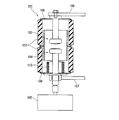
- FIG. 5 is a cross-sectional view of the sealed relay of the present invention, wherein the center line CL to the left half indicates the contact state of the first contact and the second contact, and the right half indicates the non-contact Indicates the status. Sectional drawing of a prior art example.
- reference numeral 1 denotes a vacuum relay as an example of a sealed relay
- the vacuum relay 1 is attached to the insulating cylinder 2 and an opening on one end side of the insulating cylinder 2 and has a first contact on the inner surface
- a first relay connection 4 provided with a third relay 3, a second relay connection 5 arranged opposite to the first relay connection 4 in the insulating cylinder 2 with a predetermined distance, a first relay connection 4, a second relay connection 4
- the movable member 7 is provided with a second contact 6 which is disposed between the two relay connection portions 5 so as to be movable and contacts the first contact 3 by moving it to the first relay connection portion 4 side, and the movable member 7 And an operation mechanism 8 for moving the first contact 3 and the second contact 6 in the contact / separation direction.
- a third relay connection 10 having a third contact 9 is disposed between the first relay connection 4 and the second relay connection 5.
- the movable member 7 is provided with a fourth contact 11.
- the fourth contact 11 is brought out of contact with the third contact 9 and As shown in the half, when the first contact 3 and the second contact 6 are brought out of contact, the third contact 9 is brought into contact.
- the third contact 9 and the fourth contact 11 are formed in a ring shape.
- An expandable bellows 12 is interposed between the movable member 7 and the second relay connection portion 5.
- the bellows 12 has a double structure of an inner peripheral bellows 12a and an outer peripheral bellows 12b.
- the inside of the insulating cylinder 2 is kept vacuum by the inner peripheral bellows 12a, and the movable member 7 is exclusively output by the outer peripheral bellows 12b.
- the second relay connection 5 is electrically connected.
- the inner peripheral bellows 12a is referred to as a hermetic sealing bellows
- the outer peripheral bellows 12b is referred to as a current supplying bellows).
- the insulating cylinder 2 is divided into first to third three cylindrical portions 2a to 2c, and is made of ceramic. Of the three cylindrical portions 2a to 2c, the third cylindrical portion 2c may be omitted. In this case, the operation mechanism storage portion 14 and the connection member 15 described later are formed of an insulating material such as ceramic.
- the first relay connection portion 4 is formed in a disk shape, and is attached to the upper end of the first cylindrical portion 2a with the opening sealed.
- a first contact 3 is provided at a central portion of the lower surface of the first relay connection portion 4.
- the second relay connection portion 5 has a shaft portion insertion hole 5a for inserting a shaft portion 7b of the movable member 7 to be described next in the center, and between the second cylinder portion 2b and the third cylinder portion 2c. Is attached and attached to the
- the movable member 7 has a disk-like flange 7a provided with the second contact 6 at the center of the upper surface, and a shaft 7b smaller in diameter than the flange 7a provided at the center of the lower surface of the flange 7a. Is equipped.
- the second contact 6 is provided at the central portion of the upper surface of the flange portion 7a. Further, the ring-shaped fourth contact 11 is provided at a peripheral edge portion of the lower surface of the flange portion 7 a and at a position facing the third contact 9.
- the flange portion 7a is formed of a material having excellent conductivity such as a copper alloy.
- the shaft portion 7 b protrudes from the lower portion of the second relay connection portion 5 through the shaft portion insertion hole 5 a provided in the second relay connection portion 5.
- the tip of the shaft 7 b is connected to the operation mechanism 8 via the insulating rod 13.
- the shaft portion 7 b is formed of a material such as stainless steel.
- An air cylinder is used for the operation mechanism 8.
- the operation mechanism 8 is housed in the operation mechanism housing portion 14.
- the upper end of the operation mechanism storage portion 14 is connected to the lower end of the third cylindrical portion 2 c via the connection member 15.
- the third relay connection portion 10 includes a ring-shaped main body portion 10 a and a lead portion 10 b connected to the ring-shaped main body portion 10 a.
- the outer peripheral side of the ring-shaped main body portion 10 a is sandwiched between the first cylindrical portion 2 a and the second cylindrical portion 2 b, and the inner peripheral side protrudes into the insulating cylinder 2.
- a ring-shaped third contact 9 is attached to a position of the upper surface of the ring-shaped main body 10 a protruding into the insulating cylinder 2 facing the fourth contact 11.
- the bellows 12 As described above, the bellows 12 has a double structure of the airtight sealing bellows 12a on the inner peripheral side and the energizing bellows 12b on the outer peripheral side.
- the hermetic sealing bellows 12 a is disposed on the outer periphery of the shaft 7 b in a state in which the shaft 7 b of the movable member 7 is enclosed.
- One end of the hermetic sealing bellows 12 a is attached to the second relay connection 5, and the other end is attached to the flange 7 a of the movable member 7.
- the hermetic sealing bellows 12a has hermetic sealing properties that prevent outside air from entering the insulating cylinder 2 from the shaft insertion hole 5a.
- the airtight sealing bellows 12 a is formed of an airtight material.
- the current-carrying bellows 12b on the outer peripheral side is disposed on the outer periphery of the hermetic sealing bellows 12a.
- One end of the energizing bellows 12b is attached to the second relay connection portion 5 in the same manner as the hermetic sealing bellows 12a, and the other end is attached to the flange portion 7a.
- the energizing bellows 12 b electrically connect the movable member 7 and the second relay connection portion 5.
- the energizing bellows 12 b is formed of a material having electrical conductivity.
- the movable member 7 When the movable member 7 is moved to the operation mechanism 8 side by the operation mechanism 8 from the state shown in the left half of FIG. 1, the first contact 3 and the second contact 6 do not contact as shown in the right half of FIG. And the third contact 9 and the fourth contact 11 are in contact with each other, and the second relay connection portion 5 and the second relay connection portion 5 are brought into contact with each other.
- the third relay connection portion 10 is electrically connected via the movable member 7 and the current-carrying bellows 12b.
- the third contact 9 and the fourth contact 11 are formed in a ring shape, while the first contact 3 and the second contact 6 are small in a circular shape positioned on the center line CL of the insulating cylinder 2
- FIG. By forming the first contact 3 and the second contact 6 and the third contact 9 and the fourth contact 11 in the same shape, it is possible to reduce the number of parts (type of parts) and to reduce the characteristic difference in this relay switching. , It is possible to facilitate the circuit design when using this relay.
- the current application bellows 12b since the current application is conducted by the current application bellows 12b, it is preferable that the current application bellows 12b be excellent in conductivity such as a copper alloy.
- the hermetic sealing bellows 11a and the shaft portion 7b may be made of materials such as stainless steel.
- the flange portion 7a of the movable member 7 is configured to be small and the bellows is directly attached to the shaft portion 7b, it is desirable to use a material having excellent conductivity for the shaft portion 7b.
- both of the hermetic sealing and the energization may be performed by a single bellows.
Landscapes
- Physics & Mathematics (AREA)
- Electromagnetism (AREA)
- High-Tension Arc-Extinguishing Switches Without Spraying Means (AREA)
Abstract
Description
前記操作機構で前記可動部材を移動させて前記第1コンタクトと前記第2コンタクトを接触させることにより前記ベローズ及び前記可動部材を介して前記第1,第2リレー接続部を電気的に接続する封止形リレーであって、
前記第1リレー接続部と前記第2リレー接続部の間に、第3コンタクトを有する第3リレー接続部を配置し、
前記可動部材には、前記第1コンタクトと前記第2コンタクトを非接触状態にしたときに前記第3コンタクトに接触する第4コンタクトを設けた。
(2)請求項2の発明は、第3,第4コンタクトをリング状に形成したので、両者の接触面積を大きくすることができるので、RF(高周波電流)通電に有利なものになる。また、第3,第4コンタクトをリング状に形成したので、両者の位置合わせが容易になる。更に、可動部材や第3リレー接続部に、第3,第4コンタクトに見合うリング状の凹溝を形成することにより、該凹溝にリング状のコンタクトを嵌め込んで容易にコンタクトを取り付けることができる。
(3)請求項3の発明は、第1,第2コンタクトを、前記第3,第4コンタクトと略同径のリング状に形成したので、第1,第2コンタクトを、第3,第4コンタクトと別形状に形成する場合に較べて回路設計が容易になる。(コンタクト形状の違いは、静電容量の差になり、RF(高周波電流)通電においては、回路に組み込んだときに、第1,第2コンタクト側と、第3,第4コンタクト側とで回路定数が異なってしまい、これを揃えるには回路調整が必要となる)。また、第1~第4コンタクトを同じ形状に形成することにより、部品点数(部品の種類)の削減を図ることができる。
(4)請求項4の発明は、外周側ベローズに通電性能を持たせたので可動部材と第2リレー接続を外周側の通電性を有するベローズで電気的に接続するので、RF(高周波電流)通電での大電流の通電に適したものになる。また、マルチコンタクトや平網線を使用した場合に較べて、操作機構の小型化、簡素化、操作力の低減等を図ることができる。更に、通電用ベローズで通電を行なうので、可動軸に銅合金等の導電性の高い材料を用いる必要がなくなる。
2…絶縁筒
3…第1コンタクト
4…第1リレー接続部
5…第2リレー接続部
6…第2コンタクト
7…可動部材
7a…フランジ部
7b…軸部
8…操作機構
9…第3コンタクト
10…第3リレー接続部
11…第4コンタクト
12…ベローズ
12a…内周側ベローズ(気密封止用ベローズ)
12b…外周側ベローズ(通電用ベローズ)
Claims (4)
- 絶縁筒と、該絶縁筒の一端側の開口部に取り付けられていて内面に第1コンタクトを設けた第1リレー接続部と、該第1リレー接続部に対して所定の間隔をもって配置された第2リレー接続部と、前記第1,第2リレー接続部の間に移動可能に配置されていて前記第1リレー接続部側に移動させると前記第1コンタクトに接触する第2コンタクトを備えた可動部材と、該可動部材を前記コンタクト接離方向に移動させる操作機構と、前記絶縁筒内を気密に保持するベローズと、を備え、
前記操作機構で前記可動部材を移動させて前記第1コンタクトと前記第2コンタクトを接触させることにより前記ベローズ及び前記可動部材を介して前記第1,第2リレー接続部を電気的に接続する封止形リレーであって、
前記第2リレー接続部と前記第1リレー接続部の間に、第3コンタクトを有する第3リレー接続部を配置し、
前記可動部材には、前記第1コンタクトと前記第2コンタクトを非接触状態に移動させたときに前記第3コンタクトに接触する第4コンタクトを設けたことを特徴とする封止形リレー。 - 前記第3,第4コンタクトは、略同径のリング状に形成されていることを特徴とする請求項1に記載の封止形リレー。
- 前記第1,第2コンタクトは、前記第3,第4コンタクトと略同径のリング状に形成されていることを特徴とする請求項2に記載の封止形リレー。
- 前記ベローズは、内周側ベローズと外周側ベローズの2重構造になっていて、内周側ベローズは、気密封止性能を具備し、外周側ベローズは、通電性能を具備していることを特徴とする請求項1~3の何れかに記載の封止形リレー。
Priority Applications (3)
| Application Number | Priority Date | Filing Date | Title |
|---|---|---|---|
| CN201480031993.7A CN105264630B (zh) | 2013-06-06 | 2014-05-28 | 封闭形继电器 |
| US14/896,045 US9589751B2 (en) | 2013-06-06 | 2014-05-28 | Sealed relay |
| KR1020167000184A KR101771641B1 (ko) | 2013-06-06 | 2014-05-28 | 밀봉형 릴레이 |
Applications Claiming Priority (2)
| Application Number | Priority Date | Filing Date | Title |
|---|---|---|---|
| JP2013-119364 | 2013-06-06 | ||
| JP2013119364A JP6136598B2 (ja) | 2013-06-06 | 2013-06-06 | 封止形リレー |
Publications (1)
| Publication Number | Publication Date |
|---|---|
| WO2014196427A1 true WO2014196427A1 (ja) | 2014-12-11 |
Family
ID=52008076
Family Applications (1)
| Application Number | Title | Priority Date | Filing Date |
|---|---|---|---|
| PCT/JP2014/064104 Ceased WO2014196427A1 (ja) | 2013-06-06 | 2014-05-28 | 封止形リレー |
Country Status (5)
| Country | Link |
|---|---|
| US (1) | US9589751B2 (ja) |
| JP (1) | JP6136598B2 (ja) |
| KR (1) | KR101771641B1 (ja) |
| CN (1) | CN105264630B (ja) |
| WO (1) | WO2014196427A1 (ja) |
Cited By (1)
| Publication number | Priority date | Publication date | Assignee | Title |
|---|---|---|---|---|
| CN109994342A (zh) * | 2019-04-08 | 2019-07-09 | 浙江泰华电器有限公司 | 一种带氢气的继电器及其充气方法 |
Families Citing this family (3)
| Publication number | Priority date | Publication date | Assignee | Title |
|---|---|---|---|---|
| CN106683947B (zh) * | 2016-12-20 | 2020-11-13 | 北京双杰电气股份有限公司 | 一种直流接触器 |
| JP6992717B2 (ja) * | 2018-09-20 | 2022-01-13 | 株式会社明電舎 | リレー装置 |
| CN111403231B (zh) * | 2020-03-13 | 2022-04-08 | 云南电网有限责任公司电力科学研究院 | 混合式灭弧室 |
Citations (6)
| Publication number | Priority date | Publication date | Assignee | Title |
|---|---|---|---|---|
| JPS59203326A (ja) * | 1983-04-30 | 1984-11-17 | 松下電工株式会社 | 真空リレ− |
| JPS6484533A (en) * | 1987-09-26 | 1989-03-29 | Matsushita Electric Works Ltd | Sealing contact device |
| JPH01204322A (ja) * | 1988-02-08 | 1989-08-16 | Toshiba Corp | 真空バルブ |
| JP2002313197A (ja) * | 2001-04-17 | 2002-10-25 | Meidensha Corp | 真空バルブ |
| JP2006332388A (ja) * | 2005-05-27 | 2006-12-07 | Meidensha Corp | 真空可変コンデンサ |
| JP2009004607A (ja) * | 2007-06-22 | 2009-01-08 | Meidensha Corp | 絶縁性真空機器 |
Family Cites Families (17)
| Publication number | Priority date | Publication date | Assignee | Title |
|---|---|---|---|---|
| US3562682A (en) * | 1968-06-10 | 1971-02-09 | Tokyo Shibaura Electric Co | Vacuum switching apparatus |
| US3843856A (en) * | 1973-06-04 | 1974-10-22 | Allis Chalmers | Contact for a vacuum switch of single phase alloy |
| US5892194A (en) * | 1996-03-26 | 1999-04-06 | Matsushita Electric Works, Ltd. | Sealed contact device with contact gap adjustment capability |
| JPH10284347A (ja) | 1997-04-07 | 1998-10-23 | Meidensha Corp | 真空可変コンデンサ |
| JPH10340655A (ja) | 1997-06-06 | 1998-12-22 | Mitsubishi Electric Corp | 真空バルブ |
| JP4339724B2 (ja) | 2004-03-12 | 2009-10-07 | 三菱電機株式会社 | スイッチギヤおよびスイッチギヤの製造方法 |
| JP4481808B2 (ja) | 2004-12-15 | 2010-06-16 | 株式会社東芝 | 真空開閉装置 |
| JP4988489B2 (ja) | 2007-09-19 | 2012-08-01 | 株式会社日立製作所 | 電気接点 |
| JP5214497B2 (ja) * | 2009-03-09 | 2013-06-19 | ナイルス株式会社 | プッシュスイッチ |
| CN101840814A (zh) * | 2009-03-16 | 2010-09-22 | 昆山国力真空电器有限公司 | 真空继电器 |
| US8487722B2 (en) * | 2010-03-04 | 2013-07-16 | Eaton Corporation | Thermally managed electromagnetic switching device |
| KR101357084B1 (ko) * | 2010-03-15 | 2014-02-03 | 오므론 가부시키가이샤 | 접촉 스위칭 장치 |
| CN102237222A (zh) * | 2010-04-30 | 2011-11-09 | 昆山国力真空电器有限公司 | 真空继电器 |
| US20120044030A1 (en) * | 2010-08-17 | 2012-02-23 | Wu Sung Jen | Relay with multiple coils |
| JP5842385B2 (ja) * | 2011-05-18 | 2016-01-13 | 株式会社明電舎 | ベローズおよびその製造方法 |
| DE102012102431B4 (de) * | 2012-03-21 | 2019-11-07 | Te Connectivity Germany Gmbh | Leitungsschutzschalter |
| KR101926864B1 (ko) * | 2012-06-26 | 2018-12-07 | 현대자동차주식회사 | 차량 배터리시스템의 릴레이모듈 |
-
2013
- 2013-06-06 JP JP2013119364A patent/JP6136598B2/ja active Active
-
2014
- 2014-05-28 US US14/896,045 patent/US9589751B2/en active Active
- 2014-05-28 WO PCT/JP2014/064104 patent/WO2014196427A1/ja not_active Ceased
- 2014-05-28 KR KR1020167000184A patent/KR101771641B1/ko active Active
- 2014-05-28 CN CN201480031993.7A patent/CN105264630B/zh active Active
Patent Citations (6)
| Publication number | Priority date | Publication date | Assignee | Title |
|---|---|---|---|---|
| JPS59203326A (ja) * | 1983-04-30 | 1984-11-17 | 松下電工株式会社 | 真空リレ− |
| JPS6484533A (en) * | 1987-09-26 | 1989-03-29 | Matsushita Electric Works Ltd | Sealing contact device |
| JPH01204322A (ja) * | 1988-02-08 | 1989-08-16 | Toshiba Corp | 真空バルブ |
| JP2002313197A (ja) * | 2001-04-17 | 2002-10-25 | Meidensha Corp | 真空バルブ |
| JP2006332388A (ja) * | 2005-05-27 | 2006-12-07 | Meidensha Corp | 真空可変コンデンサ |
| JP2009004607A (ja) * | 2007-06-22 | 2009-01-08 | Meidensha Corp | 絶縁性真空機器 |
Cited By (1)
| Publication number | Priority date | Publication date | Assignee | Title |
|---|---|---|---|---|
| CN109994342A (zh) * | 2019-04-08 | 2019-07-09 | 浙江泰华电器有限公司 | 一种带氢气的继电器及其充气方法 |
Also Published As
| Publication number | Publication date |
|---|---|
| JP6136598B2 (ja) | 2017-05-31 |
| US20160133405A1 (en) | 2016-05-12 |
| KR20160032087A (ko) | 2016-03-23 |
| US9589751B2 (en) | 2017-03-07 |
| JP2014238917A (ja) | 2014-12-18 |
| CN105264630A (zh) | 2016-01-20 |
| KR101771641B1 (ko) | 2017-08-25 |
| CN105264630B (zh) | 2018-11-09 |
Similar Documents
| Publication | Publication Date | Title |
|---|---|---|
| US10096942B2 (en) | Hermetically sealed manual disconnect | |
| CN103531398B (zh) | 真空开关管 | |
| CN108140506B (zh) | 用于电开关的接触装置以及电开关 | |
| JP2003536221A (ja) | 2つの接触子装置を有する真空バルブ | |
| CN105830187A (zh) | 具有真空开关室的双触点开关 | |
| WO2014196427A1 (ja) | 封止形リレー | |
| JP2015028867A (ja) | 開閉器 | |
| CN103198970B (zh) | 双断口结构的真空泡 | |
| US10910184B2 (en) | Sealed relay | |
| CN119013751A (zh) | 隔离开关 | |
| JP5319453B2 (ja) | 接地開閉装置 | |
| JP7230751B2 (ja) | 接点圧調整構造 | |
| JP2008311036A (ja) | 真空スイッチギヤ | |
| JP2003007179A (ja) | 真空バルブおよびそれを用いた電力用開閉装置 | |
| CN103165337B (zh) | 断路器及其绝缘方法 | |
| JP3810050B2 (ja) | 多機能形真空バルブ | |
| JP6992717B2 (ja) | リレー装置 | |
| CN2927309Y (zh) | 用于中压开关设备的真空开关 | |
| WO2017022510A1 (ja) | 開閉装置及びスイッチギヤ | |
| CN106847621A (zh) | 具有提高的操作精度的断开和闭合电气线路的无摩擦开关装置 | |
| JP2022006572A (ja) | 真空遮断器 | |
| JP2002313197A (ja) | 真空バルブ | |
| JP2017076462A (ja) | 真空バルブ | |
| JPH02170322A (ja) | 封止接点装置 |
Legal Events
| Date | Code | Title | Description |
|---|---|---|---|
| WWE | Wipo information: entry into national phase |
Ref document number: 201480031993.7 Country of ref document: CN |
|
| 121 | Ep: the epo has been informed by wipo that ep was designated in this application |
Ref document number: 14807028 Country of ref document: EP Kind code of ref document: A1 |
|
| WWE | Wipo information: entry into national phase |
Ref document number: 14896045 Country of ref document: US |
|
| NENP | Non-entry into the national phase |
Ref country code: DE |
|
| ENP | Entry into the national phase |
Ref document number: 20167000184 Country of ref document: KR Kind code of ref document: A |
|
| 122 | Ep: pct application non-entry in european phase |
Ref document number: 14807028 Country of ref document: EP Kind code of ref document: A1 |