WO2014196047A1 - 燃料噴射弁の制御装置 - Google Patents
燃料噴射弁の制御装置 Download PDFInfo
- Publication number
- WO2014196047A1 WO2014196047A1 PCT/JP2013/065662 JP2013065662W WO2014196047A1 WO 2014196047 A1 WO2014196047 A1 WO 2014196047A1 JP 2013065662 W JP2013065662 W JP 2013065662W WO 2014196047 A1 WO2014196047 A1 WO 2014196047A1
- Authority
- WO
- WIPO (PCT)
- Prior art keywords
- fuel
- fuel injection
- injection valve
- valve
- control device
- Prior art date
- Legal status (The legal status is an assumption and is not a legal conclusion. Google has not performed a legal analysis and makes no representation as to the accuracy of the status listed.)
- Ceased
Links
Images




Classifications
-
- F—MECHANICAL ENGINEERING; LIGHTING; HEATING; WEAPONS; BLASTING
- F02—COMBUSTION ENGINES; HOT-GAS OR COMBUSTION-PRODUCT ENGINE PLANTS
- F02M—SUPPLYING COMBUSTION ENGINES IN GENERAL WITH COMBUSTIBLE MIXTURES OR CONSTITUENTS THEREOF
- F02M61/00—Fuel-injectors not provided for in groups F02M39/00 - F02M57/00 or F02M67/00
- F02M61/16—Details not provided for in, or of interest apart from, the apparatus of groups F02M61/02 - F02M61/14
- F02M61/18—Injection nozzles, e.g. having valve seats; Details of valve member seated ends, not otherwise provided for
-
- F—MECHANICAL ENGINEERING; LIGHTING; HEATING; WEAPONS; BLASTING
- F02—COMBUSTION ENGINES; HOT-GAS OR COMBUSTION-PRODUCT ENGINE PLANTS
- F02D—CONTROLLING COMBUSTION ENGINES
- F02D41/00—Electrical control of supply of combustible mixture or its constituents
- F02D41/30—Controlling fuel injection
- F02D41/38—Controlling fuel injection of the high pressure type
- F02D41/40—Controlling fuel injection of the high pressure type with means for controlling injection timing or duration
-
- F—MECHANICAL ENGINEERING; LIGHTING; HEATING; WEAPONS; BLASTING
- F02—COMBUSTION ENGINES; HOT-GAS OR COMBUSTION-PRODUCT ENGINE PLANTS
- F02M—SUPPLYING COMBUSTION ENGINES IN GENERAL WITH COMBUSTIBLE MIXTURES OR CONSTITUENTS THEREOF
- F02M61/00—Fuel-injectors not provided for in groups F02M39/00 - F02M57/00 or F02M67/00
- F02M61/16—Details not provided for in, or of interest apart from, the apparatus of groups F02M61/02 - F02M61/14
- F02M61/18—Injection nozzles, e.g. having valve seats; Details of valve member seated ends, not otherwise provided for
- F02M61/1806—Injection nozzles, e.g. having valve seats; Details of valve member seated ends, not otherwise provided for characterised by the arrangement of discharge orifices, e.g. orientation or size
-
- F—MECHANICAL ENGINEERING; LIGHTING; HEATING; WEAPONS; BLASTING
- F02—COMBUSTION ENGINES; HOT-GAS OR COMBUSTION-PRODUCT ENGINE PLANTS
- F02D—CONTROLLING COMBUSTION ENGINES
- F02D2200/00—Input parameters for engine control
- F02D2200/02—Input parameters for engine control the parameters being related to the engine
- F02D2200/06—Fuel or fuel supply system parameters
- F02D2200/0614—Actual fuel mass or fuel injection amount
-
- F—MECHANICAL ENGINEERING; LIGHTING; HEATING; WEAPONS; BLASTING
- F02—COMBUSTION ENGINES; HOT-GAS OR COMBUSTION-PRODUCT ENGINE PLANTS
- F02D—CONTROLLING COMBUSTION ENGINES
- F02D41/00—Electrical control of supply of combustible mixture or its constituents
- F02D41/30—Controlling fuel injection
- F02D41/38—Controlling fuel injection of the high pressure type
- F02D41/40—Controlling fuel injection of the high pressure type with means for controlling injection timing or duration
- F02D41/402—Multiple injections
-
- Y—GENERAL TAGGING OF NEW TECHNOLOGICAL DEVELOPMENTS; GENERAL TAGGING OF CROSS-SECTIONAL TECHNOLOGIES SPANNING OVER SEVERAL SECTIONS OF THE IPC; TECHNICAL SUBJECTS COVERED BY FORMER USPC CROSS-REFERENCE ART COLLECTIONS [XRACs] AND DIGESTS
- Y02—TECHNOLOGIES OR APPLICATIONS FOR MITIGATION OR ADAPTATION AGAINST CLIMATE CHANGE
- Y02T—CLIMATE CHANGE MITIGATION TECHNOLOGIES RELATED TO TRANSPORTATION
- Y02T10/00—Road transport of goods or passengers
- Y02T10/10—Internal combustion engine [ICE] based vehicles
- Y02T10/40—Engine management systems
Definitions
- the present invention relates to a control device for a fuel injection valve. Specifically, the present invention relates to a control device for a fuel injection valve having a slit nozzle. More specifically, the present invention relates to a control device for a fuel injection valve having a slit nozzle, which can reduce deterioration of the homogeneity of the air-fuel mixture during in-cylinder injection in the compression stroke.
- the purpose is to reduce particulate matter (PM) caused by interference between fuel spray and an intake valve, and to reduce oil dilution caused by adhesion of fuel spray to the bore inner wall.
- PM particulate matter
- the compression stroke it has been proposed to perform the compression stroke injection in which fuel is injected from the fuel injection valve.
- the air flow (for example, tumble flow) in the cylinder (combustion chamber) is weaker than the intake stroke injection in which fuel is injected from the fuel injection valve in the intake stroke. For this reason, when compression stroke injection is performed in a direct injection engine, the homogeneity of the air-fuel mixture in the cylinder deteriorates (homogeneity decreases). As a result, for example, there is an increased risk of causing problems such as a decrease in exhaust gas cleanliness (a decrease in emissions) and an increase in torque fluctuation.
- the fuel injection valve provided with the slit nozzle as described above makes the shape of the fuel spray injected from the nozzle hole non-uniform in the circumferential direction around the injection direction as the entire fuel spray injected into the nozzle hole. be able to.
- the spray of fuel injected from the nozzle hole of the fuel injection valve provided with the slit nozzle has, for example, a fan shape, and the concentration of fuel at both end portions of the fan spray is compared to other portions. And high (that is, the fuel distribution in the spray is non-uniform) and has a high penetration force.
- the air-fuel mixture in the cylinder caused by the fact that the air flow in the cylinder in the compression stroke is weaker than that in the intake stroke as compared with the fuel injection valve provided with a general nozzle.
- the homogeneity to deteriorate, and as a result, there is a higher possibility of causing problems such as a reduction in emissions and an increase in torque fluctuation. Accordingly, there is a need in the art for a control device for a fuel injection valve having a slit nozzle that can reduce the deterioration of the homogeneity of the air-fuel mixture during in-cylinder injection in the compression stroke.
- a control device for a fuel injection valve having a slit nozzle that can reduce the deterioration of the homogeneity of the air-fuel mixture during in-cylinder injection in the compression stroke. That is, it is an object of the present invention to provide a control device for a fuel injection valve having a slit nozzle, which can reduce the deterioration of the homogeneity of the air-fuel mixture during in-cylinder injection in the compression stroke.
- the above object of the present invention is to A valve seat formed around a nozzle hole having a slit-like shape, and a valve body that closes the nozzle hole by sitting on the valve seat part and opens the nozzle hole by moving away from the valve seat part And a control device for a fuel injection valve that directly injects fuel into a cylinder, When fuel is injected in the compression stroke, at least once, the lift amount, which is the amount of movement of the valve body from the state in which the valve body is seated on the valve seat portion, is a maximum that is a predetermined maximum amount. Injecting fuel from the fuel injection valve by a partial lift system which is an injection system for reducing the lift amount before reaching the lift amount; This is achieved by the control device of the fuel injection valve.
- a control device for a fuel injection valve equipped with a slit nozzle which can reduce the deterioration of the homogeneity of the air-fuel mixture during in-cylinder injection in the compression stroke.
- problems such as a reduction in emissions and an increase in torque fluctuation can be reduced.
- FIG. 1 is a schematic diagram showing an example of the configuration of an internal combustion engine to which a control device for a fuel injection valve according to one embodiment of the present invention is applied.
- FIG. 2 is a schematic diagram showing an example of the configuration of the fuel injection valve provided in the internal combustion engine to which the control device for the fuel injection valve according to one embodiment of the present invention is applied.
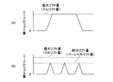
- FIG. 3A is a schematic graph showing a change in the lift amount of the valve body (needle) at the time of injection by the full lift method
- FIG. 3B is a change of the lift amount of the needle at the time of injection by the partial lift method. It is a typical graph which shows.
- FIG. 3A is a schematic graph showing a change in the lift amount of the valve body (needle) at the time of injection by the full lift method
- FIG. 3B is a change of the lift amount of the needle at the time of injection by the partial lift method. It is a typical graph which shows.
- FIG. 3A is a schematic graph showing a
- FIG. 4 is a schematic diagram showing an example of the configuration of the injection hole of the fuel injection valve provided in the internal combustion engine to which the control device for the fuel injection valve according to one embodiment of the present invention is applied, and its surroundings.
- FIG. 5 is a schematic diagram for explaining fuel injection control by the fuel injection valve control apparatus according to one embodiment of the present invention.
- FIG. 6 is a schematic diagram for explaining fuel injection control by the control device for a fuel injection valve according to another embodiment of the present invention.
- FIG. 7 is a schematic diagram for explaining fuel injection control by the fuel injection valve control apparatus according to still another embodiment of the present invention.
- the present invention provides a control device for a fuel injection valve including a slit nozzle, which can reduce the deterioration of the homogeneity of the air-fuel mixture during in-cylinder injection in the compression stroke.
- a control device for a fuel injection valve including a slit nozzle which can reduce the deterioration of the homogeneity of the air-fuel mixture during in-cylinder injection in the compression stroke.
- the present inventor has found that the degree of deviation from the valve seat portion of the valve body that opens and closes the fuel injection valve is higher than usual when fuel is injected into the cylinder in the compression stroke.
- partial lift system By making it small (so-called “partial lift system”), it has been found that the homogeneity of the air-fuel mixture in the cylinder can be ensured even in the fuel injection in the compression stroke by the fuel injection valve provided with the slit nozzle. It has come to be.
- the first embodiment of the present invention is: A valve seat formed around a nozzle hole having a slit-like shape, and a valve body that closes the nozzle hole by sitting on the valve seat part and opens the nozzle hole by moving away from the valve seat part And a control device for a fuel injection valve that directly injects fuel into a cylinder, When fuel is injected in the compression stroke, at least once, the lift amount, which is the amount of movement of the valve body from the state in which the valve body is seated on the valve seat portion, is a maximum that is a predetermined maximum amount. Injecting fuel from the fuel injection valve by a partial lift system which is an injection system for reducing the lift amount before reaching the lift amount; It is a control apparatus of a fuel injection valve.
- the control device for the fuel injection valve closes the nozzle hole by seating on the valve seat part formed around the nozzle hole having a slit shape and the valve seat part.
- the present invention is applied to a fuel injection valve that includes a valve body that opens the nozzle hole by separating from the valve seat portion and injects fuel directly into a cylinder.
- the fuel injection valve is in a state in which the valve body is seated in the valve seat portion in a lift amount that is a movement amount of the valve body from a state in which the valve body is seated in the valve seat portion.
- the fuel injection valve is adjustable between a minimum lift amount in a (fully closed state) and a maximum lift amount in a state where the valve body is farthest from the valve seat portion (fully opened state).
- a specific configuration of a fuel injection valve including a slit nozzle having such a slit-like nozzle shape is well known to those skilled in the art (see, for example, Patent Document 1).
- An example of the configuration of the fuel injection valve including a slit nozzle having a slit-like nozzle hole shape will be described in detail later with reference to the accompanying drawings.
- the fuel injection valve having the slit nozzle as described above is not suitable in the circumferential direction around the injection direction of the entire fuel spray injected from the injection hole. It can be made uniform.
- the spray of fuel injected from the nozzle hole of the fuel injection valve provided with the slit nozzle has, for example, a fan shape, and the concentration of fuel at both end portions of the fan spray is compared to other portions. And high (that is, the fuel distribution in the spray is non-uniform) and has a high penetration force.
- a fuel injection valve provided with a slit nozzle can enable stratified combustion in a wider range of operating conditions, for example.
- FIG. 1 is a schematic diagram showing an example of the configuration of an internal combustion engine to which a control device for a fuel injection valve according to one embodiment of the present invention is applied as described above.
- FIG. 1 is a schematic diagram showing an example of the configuration of an internal combustion engine to which a control device for a fuel injection valve according to one embodiment of the present invention is applied as described above.
- 1, 10 is a body of an internal combustion engine (hereinafter referred to as “engine body”), 11 is a fuel injection valve, 12 is a cylinder head, 13 is a cylinder block, 14 is an intake valve, 15 is an exhaust valve, 16 is a spark plug, 17 Is an in-cylinder pressure sensor, 18 is a combustion chamber, 19 is a piston, and 90 is an electronic control unit (ECU).
- engine body an internal combustion engine
- 11 is a fuel injection valve
- 12 is a cylinder head
- 13 is a cylinder block
- 14 is an intake valve
- 15 is an exhaust valve
- 16 is a spark plug
- 17 Is an in-cylinder pressure sensor
- 18 is a combustion chamber
- 19 is a piston
- 90 is an electronic control unit
- the fuel injection valve 11 is attached to a part of the engine body 10 (for example, a part of the cylinder head 12 or a part of the cylinder block 13) on the side of the intake valve 14 in the upper part of the cylinder (that is, the combustion chamber 18).
- the electronic control unit (ECU) 90 is, for example, a cylinder pressure sensor 17, a crank angle sensor that outputs a signal corresponding to the rotational position (ie, crank angle) of the crankshaft, a cam position sensor, and the like (not shown). Based on the signal from the sensor, the operating state of the engine body 10 is acquired, and for example, the opening operation of the needle valve in the fuel injection valve 11 is controlled according to the acquired operating state of the engine body 10.
- the fuel injection amount and injection timing can be adjusted, and the ignition timing by the spark plug 16 can be adjusted. Further, the electronic control unit (ECU) 90 controls the valve opening operation of the needle valve in the fuel injection valve 11 when, for example, fuel is injected in the compression stroke, and the fuel injection method by the fuel injection valve 11 is fully lifted. It is also possible to execute control to switch from the method to the partial lift method.
- ECU electronice control unit
- FIG. 2 is a schematic diagram showing an example of the configuration of the fuel injection valve included in the internal combustion engine to which the control device for the fuel injection valve according to one embodiment of the present invention is applied as described above.
- 30 is a nozzle
- 31 is a needle valve
- 32 is a fuel injection hole (hereinafter “injection hole”)
- 33 is a fuel passage
- 34 is a solenoid
- 35 is a spring
- 36 is a fuel intake port
- 37 is an injection valve.
- Each axis is shown.
- the injection valve axis 37 is an axis extending in the longitudinal direction of the fuel injection valve 11.
- the fuel injection valve 11 shown in FIG. 2 is a so-called “inner open type” fuel injection valve.
- the fuel injection valve 11 can selectively execute either one of injection by a full lift method or injection by a partial lift method.
- the full lift injection is fuel injection that raises the needle valve 31 to the maximum lift amount (that is, maximum lift injection).
- this is fuel injection (that is, partial lift injection) that raises the needle valve 31 only to a lift amount smaller than the maximum lift amount.
- the needle lift amount can be controlled by controlling the energization time to the fuel injection valve 11.
- FIG. 3A shows the transition of the needle lift amount in one full lift injection
- FIG. 3B shows the transition of the needle lift amount over three partial lift injections. Has been.
- FIG. 4 is a schematic diagram showing an example of the configuration of the injection hole of the fuel injection valve provided in the internal combustion engine to which the control device for the fuel injection valve according to one embodiment of the present invention is applied, and its peripheral configuration as described above. is there. More specifically, FIG. 4 shows the configuration of the injection hole 32 of the fuel injection valve 11 shown in FIG.
- FIG. 4A shows the tip of the fuel injection valve 11 when the tip of the fuel injection valve 11 is viewed from the outside of the fuel injection valve 11 along the injection valve axis 37.
- FIG. 4B shows a cross section of the tip of the fuel injection valve 11 (hereinafter “cross section BB”) by a plane including the line BB and the injection hole central axis 47 shown in FIG. 4A.
- 4 (C) shows a cross section of the tip of the fuel injection valve 11 by a plane passing through the line CC shown in FIG. 4 (A) and parallel to the injection valve axis 37.
- 30 is a nozzle
- 31 is a needle valve
- 32 is an injection hole
- 37 is an injection valve axis
- 38 is a sack
- 39 is a needle seat portion (hereinafter “sheet portion”)
- 40 is a nozzle seat wall surface
- 41 is a needle.
- the sheet wall surface, 42 is the nozzle hole central region
- 43 is the nozzle hole end region
- 44 is the inlet
- 45 is the outlet
- 46 is the sack center
- 47 is the nozzle central axis
- 48 is the nozzle end axis.
- the sack center 46 is the center of the space constituting the sack 38 and is a point on the injection valve axis 37.
- the nozzle seat wall surface 40 is a wall surface on which the needle seat wall surface 41 is seated (of the valve seat portion) when the fuel injection valve 11 is fully closed (that is, when the needle lift amount becomes zero).
- the nozzle hole central axis 47 is an axis passing through the center of the nozzle hole 32 in the fuel flow direction (that is, the direction in which fuel flows in the nozzle hole).
- the nozzle hole end axis 48 is an axis that penetrates the end of the nozzle hole 13 in the fuel flow direction.
- the nozzle hole 32 has an inlet 44 and an outlet 45.
- the inlet 44 is open to the sack 38, and the fuel flows into the injection hole 32 through the inlet 44.
- the outlet 45 is open to the outside of the fuel injection valve 11, and the fuel is injected from the outlet 45.
- the inner region of the nozzle hole 32 is divided into a nozzle hole central region 42 and a nozzle hole end region 43.
- the nozzle hole central region 42 is a region extending from the inlet 44 to the outlet 45 along the nozzle central axis 47.
- the nozzle hole end region 43 is a region that extends from the inlet 44 to the outlet 45 along each nozzle hole end axis 48 on both sides of the nozzle hole central region 42.
- the nozzle hole 32 when the nozzle hole 32 is viewed in cross section, the nozzle hole 32 has a specific direction (a direction parallel to the line BB in FIG. 4 (A)).
- such a nozzle hole shape is referred to as a “slit-shaped nozzle hole shape”.
- the shape of the cross section of the “slit-shaped nozzle hole” does not necessarily have to be a rectangle, for example, a corner is rounded. Alternatively, it may have an oval shape as a whole.
- the cross section of the injection hole is a cross section when the injection hole is cut along a plane perpendicular to the injection hole central axis 47.
- the nozzle hole 32 when the nozzle hole 32 is viewed in the cross section BB, the nozzle hole 32 has a fan-shaped shape extending from the inlet 44 toward the outlet 45. Therefore, the flow path cross section of the nozzle hole 32 gradually increases from the inlet 44 toward the outlet 45. As a result, the channel area of the outlet 45 is larger than the channel area of the inlet 44.
- the cross section BB is a cross section when the nozzle hole is cut along one plane including the nozzle hole central axis 47 and each nozzle hole end axis 48 as described above.
- FIG. 4C when the nozzle hole 32 is viewed in its longitudinal section, the nozzle hole 32 has a substantially rectangular shape.
- the vertical cross section of the injection hole is a cross section when cut along one plane including the injection hole central axis 47 and the injection valve axis 37.
- the nozzle hole 32 is formed so that the nozzle hole center axis 47 and the nozzle hole end axis 48 intersect the sack center 46. It is formed at the tip.
- the injection hole 32 is formed at the tip of the nozzle 30 so that the injection hole central axis 47 forms a certain angle with respect to the injection valve axis 37.
- the injection hole 32 may be formed at the tip of the nozzle 30 so that the injection hole central axis 47 coincides with the injection valve axis 37.
- the purpose is to reduce the PM caused by the interference between the fuel spray and the intake valve, and to reduce the oil dilution caused by the fuel spray adhering to the inner wall of the bore.
- compression stroke injection in which fuel is injected from the fuel injection valve in the compression stroke.
- the temperature of the engine is low, such as during a cold start, it is difficult to vaporize the fuel, and therefore, an increase in PM and oil dilution are more likely to occur, thus increasing the need for compression stroke injection.
- the valve body when fuel is injected in the compression stroke, the valve body is seated on the valve seat portion at least once.
- the fuel is injected from the fuel injection valve by a partial lift method that reduces the lift amount before the lift amount that is the amount of movement of the valve body reaches the maximum lift amount that is a predetermined maximum amount.
- a partial lift method that reduces the lift amount before the lift amount that is the amount of movement of the valve body reaches the maximum lift amount that is a predetermined maximum amount.
- the air flow in the cylinder is weaker than the intake stroke injection in which the fuel is injected from the fuel injection valve in the intake stroke. Therefore, in particular, in the fuel injection valve having the slit nozzle, the possibility that the homogeneity of the air-fuel mixture in the cylinder is deteriorated is further increased as compared with the fuel injection valve having a general nozzle.
- the control device for a fuel injection valve according to the present embodiment when fuel is injected in the compression stroke, the fuel is injected from the fuel injection valve by the partial lift method at least once. As a result, fuel spray spots can be reduced and the fuel can be injected more uniformly. For example, it is possible to reduce the possibility of causing problems such as a reduction in emissions and an increase in torque fluctuation.
- the control device for a fuel injection valve according to the present invention performs partial lift injection at least once when fuel is injected in a compression stroke in a fuel injection valve having a slit nozzle.
- the spray spots of fuel can be reduced, and the homogeneity of the air-fuel mixture in the cylinder can be ensured even in the compression stroke where the airflow in the cylinder is weak.
- the control device for the fuel injection valve according to the present invention does not prohibit full lift injection in the compression stroke. That is, the fuel injection valve control apparatus according to the present invention may perform full lift injection when the airflow in the cylinder is sufficiently strong even in, for example, compression stroke injection.
- FIG. 5 is a schematic diagram for explaining the fuel injection control by the control device for the fuel injection valve according to one embodiment of the present invention, as described above.
- the lower part of FIG. 5 shows a schematic graph showing the relationship between the flow velocity of the airflow in the cylinder (tumble flow in the example shown in FIG. 5) and the crank position (crank angle [°]).
- the crank position is in a range from 360 ° to 180 °
- the flow velocity of the airflow in the cylinder is relatively large.
- the compression stroke in the example shown in FIG.
- the crank position is in the range from 180 ° to 0 °
- the flow rate of the airflow in the cylinder is relatively small. Therefore, as described above, when the compression stroke injection is executed in the direct injection engine, the homogeneity of the air-fuel mixture in the cylinder is deteriorated as compared with the intake stroke injection. As a result, for example, the emission is reduced and the torque fluctuation is reduced. The possibility of incurring problems such as an increase is increased.
- FIG. 5 schematically shows the shape of fuel spray injected from the fuel injection valve having the slit nozzle when the lift amount of the valve body is large and small. More specifically, the shape of the fuel spray injected from the fuel injection valve provided with the slit nozzle when the lift amount is large is schematically shown on the left side in FIG. On the other hand, the shape of the fuel spray injected from the fuel injection valve provided with the slit nozzle when the lift amount is small is schematically shown on the right side in FIG.
- the flow rate of fuel injected from the fuel injection valve is large as shown on the upper left side of FIG.
- the fuel spray injected from the nozzle hole of the fuel injection valve has a non-uniform shape in the circumferential direction about the injection direction as a whole spray, and the fuel distribution in the fuel spray is non-uniform.
- the fuel spray injected from the injection hole of the fuel injection valve has a feature that the penetration force is large.
- the shape of the fuel spray is substantially fan-shaped, and the concentration of fuel at both end portions of the substantially fan-shaped spray is higher than that of the other portions.
- the airflow in the cylinder is weaker than that in the intake stroke injection as described above.
- the tendency to deteriorate the homogeneity of is further increased.
- the possibility of causing problems such as a reduction in emissions and an increase in torque fluctuation is further increased.
- the fuel spray injected from the nozzle hole of the fuel injection valve has a uniform shape in the circumferential direction about the injection direction as a whole spray, and the fuel distribution in the fuel spray is uniform.
- the shape of the fuel spray is substantially conical, and the fuel concentration is uniform throughout the substantially conical spray.
- the partial lift system is used when fuel is injected in the compression stroke as shown by the schematic time chart shown in the upper part of the graph shown in the lower part of FIG.
- the control device for the fuel injection valve according to the present embodiment even when the compression stroke injection is performed using the fuel injection valve including the slit nozzle, for example, the emission is reduced, the torque fluctuation is increased, etc. The possibility of causing problems can be reduced.
- the horizontal axis is the crank position and the horizontal axis is the fuel injection amount. Therefore, it means that the longer the horizontal width of the rectangular peak drawn on the time chart is, the longer the time is, and the higher the height, the larger the injection amount.
- the above time chart schematically represents the transition of the fuel injection amount with respect to the crank position, and does not strictly represent the transition of the fuel injection amount with respect to the crank position. That is, in the above time chart, the transition of the fuel injection amount in each injection is represented by a rectangle, but the actual transition of the fuel injection amount corresponds to the transition of the needle lift amount as shown in FIG. It goes without saying that it becomes.
- the control device for a fuel injection valve according to the present embodiment even in a direct injection engine using a fuel injection valve having a slit nozzle, the deterioration of the homogeneity of the air-fuel mixture during in-cylinder injection in the compression stroke is reduced. can do. As a result, for example, problems such as a reduction in emissions and an increase in torque fluctuation can be reduced.
- the type of the engine that uses the fuel injection valve to which the control device for the fuel injection valve according to the present invention is applied is not particularly limited, and may be, for example, a gasoline engine that uses gasoline as fuel, Or the diesel engine which uses light oil etc. as a fuel may be sufficient, for example.
- the number of fuel injections by the partial lift method executed by the fuel injection valve control apparatus is, for example, the total amount of fuel injection required per cycle according to the operating state of the engine. It can be set as appropriate based on the relationship with the amount of fuel that can be injected by one injection by the partial lift method. Specifically, for example, when it is possible to inject the total amount of fuel injection required per cycle according to the operating state of the engine by one injection by the partial lift method, the partial lift method The number of fuel injections may be one, or two or more.
- the partial lift method is used.
- the number of fuel injections may be equal to the smallest integer greater than N (M times), or may be M + 1 times or more.
- intake stroke injection in which fuel is injected from the fuel injection valve in the intake stroke may be performed.
- the air flow in the cylinder is larger in the intake stroke than in the compression stroke. Therefore, in the intake stroke, when the fuel injection valve provided with the slit nozzle is opened at the maximum lift amount and the fuel is injected, the fuel distribution in the fuel spray becomes uneven, but the mixture in the cylinder Homogeneity can be ensured.
- the second embodiment of the present invention is A control device for a fuel injection valve according to the first embodiment of the present invention, comprising: In the case of injecting fuel in the compression stroke, if the required injection amount of fuel is equal to or greater than a predetermined upper limit amount, a part of the required injection amount is taken from the fuel injection valve at the maximum lift amount in the intake stroke.
- Spray It is a control apparatus of a fuel injection valve.
- the required injection amount refers to, for example, the total amount of fuel injection required per cycle according to the engine operating conditions. For example, at a high load, the required fuel injection amount Will increase.
- the predetermined upper limit amount is the maximum amount of fuel that can be injected by the partial lift method within a predetermined period in the compression stroke using the fuel injection valve to which the control device for the fuel injection valve according to this embodiment is applied. You may set as a value corresponding to a value.
- the predetermined upper limit amount may be a predetermined constant, for example, a variable that varies according to the operating condition of the engine.
- the predetermined upper limit amount is set as a value that decreases as the engine speed increases, for example, corresponding to the time length of the compression stroke decreasing as the engine speed increases. May be.
- the fuel injection valve to which the control device for the fuel injection valve according to this embodiment is applied is used.
- the fuel injection valve to which the control device for the fuel injection valve according to this embodiment is applied is used.
- the fuel injection valve to which the control device for the fuel injection valve according to this embodiment is applied is used.
- the fuel injection valve to which the control device for the fuel injection valve according to this embodiment is applied is used.
- the partial lift injection there is a high possibility that it will be difficult to inject the required amount of fuel within a predetermined period in the compression stroke.
- it is difficult to maintain a predetermined air-fuel ratio in the engine which may lead to problems such as a decrease in engine output and deterioration in emissions due to poor combustion, for example.
- the control device for the fuel injection valve according to the present embodiment is required even when the fuel is injected in the compression stroke when the required injection amount of the fuel is equal to or larger than the predetermined upper limit amount.
- a part of the injection amount is injected from the fuel injection valve at the maximum lift amount in the intake stroke. This makes it impossible to inject all of the required injection amount of fuel only by injection in the partial lift method in the compression stroke, but in addition to injection of the maximum lift amount in the intake stroke, Can be injected.
- it becomes easy to maintain a predetermined air-fuel ratio in the engine and problems such as a decrease in engine output and deterioration in emissions due to poor combustion can be reduced, for example.
- the air flow in the cylinder is larger in the intake stroke than in the compression stroke. Therefore, in the intake stroke, when the fuel injection valve provided with the slit nozzle is opened at the maximum lift amount and the fuel is injected, the fuel distribution in the fuel spray becomes non-uniform, but the cylinder has a larger air flow. The homogeneity of the air-fuel mixture can be ensured. In addition, when the fuel injection valve provided with the slit nozzle is opened at the maximum lift amount and the fuel is injected, as described above, the penetration force of the fuel spray is large.
- the fuel injection valve including the slit nozzle is configured to inject fuel in a direction that can accelerate the airflow generated in the cylinder during the intake stroke
- the fuel injection valve including the slit nozzle is set to the maximum lift amount.
- the airflow can be further increased by a synergistic effect with the airflow in the cylinder (for example, a tumble flow).
- a synergistic effect with the airflow in the cylinder (for example, a tumble flow).
- the homogeneity of the air-fuel mixture in the cylinder can be further enhanced, and for example, desirable effects such as deposit suppression can be further enhanced.
- FIG. 6 is a schematic diagram for explaining the fuel injection control by the control device for the fuel injection valve according to another embodiment of the present invention as described above.
- a time chart schematically showing the transition of the fuel injection amount relative to the crank position is shown at the top of the graph, with the crank position as the horizontal axis and the fuel injection amount as the horizontal axis.
- . 6 is the same as FIG. 5 except that in the time chart, not only the fuel injection in the partial lift method in the compression stroke but also the fuel injection in the maximum lift amount (full lift method) in the intake stroke is also described.
- FIG. 5 is the same as FIG. 5 except that in the time chart, not only the fuel injection in the partial lift method in the compression stroke but also the fuel injection in the maximum lift amount (full lift method) in the intake stroke is also described.
- the time chart shown in FIG. 6 shows that when the fuel is injected in the compression stroke, which is executed by the control device for the fuel injection valve according to this embodiment, the required injection amount of the fuel is not less than a predetermined upper limit amount.
- the fuel injection pattern in a certain case is shown. Specifically, in the injection pattern shown in FIG. 6, not only the fuel injection by the partial lift system in the compression stroke (in the example shown in FIG. 6, the crank position is in the range from 180 ° to 0 °), but also the intake stroke. Fuel injection with the maximum lift amount in the crank position range of 360 ° to 180 ° in the example shown in FIG. 6 is also executed.
- the fuel injection valve control device when the required injection amount of the fuel is equal to or larger than the predetermined upper limit amount, the fuel injection valve control device requires only the partial lift method injection in the compression stroke. Although not all of the injection amount of fuel can be injected, all of the required injection amount of fuel can be injected together with the injection with the maximum lift amount in the intake stroke. As a result, it becomes easy to maintain a predetermined air-fuel ratio in the engine, and problems such as a decrease in engine output and deterioration in emissions due to poor combustion can be reduced, for example.
- the fuel injection valve having the slit nozzle when the lift amount of the valve body is large, the flow rate of the fuel injected from the fuel injection valve is large. Further, the fuel spray injected from the nozzle hole of the fuel injection valve has a non-uniform shape in the circumferential direction about the injection direction as a whole spray, and the fuel distribution in the fuel spray is non-uniform. . Further, the fuel spray injected from the injection hole of the fuel injection valve has a feature that the penetration force is large. In the example shown in FIG. 6, the shape of the fuel spray is substantially fan-shaped, and the concentration of fuel at both end portions of the substantially fan-shaped spray is higher than the other portions.
- the flow velocity of the airflow in the cylinder in the intake stroke is larger than the flow velocity of the airflow in the cylinder in the compression stroke. Therefore, in the intake stroke, when the fuel injection valve provided with the slit nozzle is opened at the maximum lift amount and the fuel is injected, the fuel distribution in the fuel spray becomes non-uniform, but the cylinder has a larger air flow. The homogeneity of the air-fuel mixture can be ensured.
- the fuel injection valve including the slit nozzle when configured to inject fuel in a direction that can accelerate the airflow generated in the cylinder in the intake stroke, the fuel injection valve including the slit nozzle By opening the valve with the maximum lift amount and injecting the fuel, the airflow can be further increased by a synergistic effect with the airflow (for example, tumble flow) in the cylinder.
- a synergistic effect with the airflow for example, tumble flow
- desirable effects such as deposit suppression can be further increased.
- the fuel injection valve control device in a direct injection engine that uses a fuel injection valve including a slit nozzle, when the required injection amount of fuel is equal to or greater than a predetermined upper limit amount, Even when fuel is injected in the compression stroke, a part of the required injection amount is injected from the fuel injection valve at the maximum lift amount in the intake stroke. Thereby, it is possible to inject all of the required injection amount of fuel while reducing the deterioration of the homogeneity of the air-fuel mixture during the in-cylinder injection in the compression stroke.
- the horizontal axis represents the crank position and the horizontal axis represents the fuel injection amount, as in FIG. Therefore, it means that the longer the horizontal width of the rectangular peak drawn on the time chart is, the longer the time is, and the higher the height, the larger the injection amount.
- the above time chart schematically represents the transition of the fuel injection amount with respect to the crank position, and does not strictly represent the transition of the fuel injection amount with respect to the crank position. That is, in the above time chart, the transition of the fuel injection amount in each injection is represented by a rectangle, but the actual transition of the fuel injection amount corresponds to the transition of the needle lift amount as shown in FIG. It goes without saying that it becomes.
- fuel injection by the partial lift method in the compression stroke is performed a plurality of times (three times in FIG. 6).
- the number of fuel injections by the partial lift method executed by the control device for the fuel injection valve is, for example, the total amount of fuel injection required per cycle in accordance with the engine operating conditions. It can be set as appropriate based on the relationship with the amount of fuel that can be injected by one injection by the partial lift method.
- the flow velocity of the airflow in the cylinder in the compression stroke is smaller than the flow velocity of the airflow in the cylinder in the intake stroke.
- the flow velocity of the airflow in the cylinder is not constant, and changes with time even during the compression stroke.
- the fuel injection is performed with the partial lift method with a uniform lift amount in the compression stroke in which the flow velocity of the airflow in the cylinder changes over time, it corresponds to fluctuations in the flow velocity of the airflow in the cylinder at the time of fuel injection.
- the homogeneity of the air-fuel mixture in the cylinder may change.
- there is an increased risk of causing problems such as a reduction in emissions and an increase in torque fluctuation. Therefore, it is desirable to maintain the homogeneity of the air-fuel mixture in the cylinder at a certain level when performing the compression stroke injection in which fuel is injected from the fuel injection valve in the compression stroke.
- the fuel spray homogeneity is set to the fuel injection. It is desirable to adapt to the flow velocity of the airflow in the cylinder at the time. Specifically, it is desirable to increase the homogeneity of the fuel spray as the flow velocity of the airflow in the cylinder during fuel injection decreases.
- the maximum lift amount of the valve body the lift amount when the lift amount is reduced before reaching the maximum lift amount
- the third embodiment of the present invention A control device for a fuel injection valve according to any one of the first and second embodiments of the present invention, In the compression stroke, the maximum value of the lift amount of the valve body when fuel is injected from the fuel injection valve by the partial lift method is decreased as the flow velocity of the airflow in the cylinder at the time of fuel injection is smaller. It is a control apparatus of a fuel injection valve.
- the control device for the fuel injection valve according to the present embodiment determines the maximum value of the lift amount of the valve body when fuel is injected from the fuel injection valve by the partial lift method in the compression stroke.
- the homogeneity of the air-fuel mixture in the cylinder is maintained at a constant level even in the case of performing the compression stroke injection in which the fuel is injected from the fuel injection valve in the compression stroke in which the flow velocity of the airflow in the cylinder changes with time. can do.
- problems such as a reduction in emissions and an increase in torque fluctuation can be reduced.
- the transition of the flow velocity of the airflow in the cylinder during the compression stroke can be measured in advance, for example, by a prior model experiment.
- the maximum value of the lift amount of the valve body that can maintain the homogeneity of the air-fuel mixture in the cylinder at a certain level at various flow rates of the airflow in the cylinder is also based on, for example, a preliminary model experiment. It can be specified in advance.
- the correspondence relationship between the flow velocity of the air flow in the cylinder and the maximum value of the lift amount of the valve body suitable for the flow velocity is, for example, that of the fuel injection valve to which the control device for the fuel injection valve according to this embodiment is applied.
- a data table for example, a storage device (for example, Read Only Memory), a RAM (Random Access Memory), a HDD (Hard Disk Drive), etc. provided in an electronic control unit (ECU: Electronic Control Unit) that controls the engine to be used. , A data map, etc.) can be stored in advance.
- ECU Electronic Control Unit
- the CPU can refer to the maximum value of the lift amount of the valve body according to the flow velocity of the air flow in the cylinder at the time of fuel injection.
- control device for the fuel injection valve also includes all the fuel of the required injection amount depending on only the partial lift type injection in the compression stroke, as described in the second embodiment of the present invention. If the fuel injection valve cannot be injected, the fuel injection valve may be controlled so as to inject all of the required injection amount of fuel together with the injection at the maximum lift amount in the intake stroke.
- the flow velocity of the airflow in the cylinder is time. It shows a tendency to decrease over time.
- the flow rate of the air flow in the cylinder at the time of fuel injection is smaller as the injection executed later in time. As the injection is performed later, the homogeneity of the air-fuel mixture in the cylinder may deteriorate.
- the maximum value of the lift amount of the valve body in each injection is the flow velocity of the air flow in the cylinder. It is desirable that the fuel spray is more homogeneous as the injection is performed later in time by setting so as to decrease with the passage of time in accordance with the above change.
- the fourth embodiment of the present invention is A control device for a fuel injection valve according to the third embodiment of the present invention, comprising: When injecting fuel from the fuel injection valve a plurality of times by the partial lift method in the compression stroke, the maximum value of the lift amount of the valve body is made smaller as the injection is performed later in time, It is a control apparatus of a fuel injection valve.
- the control device for the fuel injection valve according to the present embodiment determines the maximum value of the lift amount of the valve body when fuel is injected from the fuel injection valve a plurality of times by the partial lift method in the compression stroke. The smaller the injection is performed later in time.
- the flow velocity of the air flow in the cylinder in the compression stroke is the time in the period in which the compression stroke injection is performed a plurality of times by the partial lift method. In the case of showing a tendency to decrease with time, the spray homogeneity can be increased as the injection is performed later in time.
- FIG. 7 is a schematic diagram for explaining the fuel injection control by the control device for the fuel injection valve according to still another embodiment of the present invention as described above.
- FIG. 7 similar to FIGS. 5 and 6, a schematic diagram showing the relationship between the flow velocity of the airflow in the cylinder (tumble flow in the example shown in FIG. 7) and the crank position (crank angle [°]).
- a simple graph is shown. As shown by the graph, in the intake stroke (in the example shown in FIG.
- the crank position is in the range from 360 ° to 180 °), the flow velocity of the airflow in the cylinder is relatively large, and the compression stroke (FIG. In the example shown in FIG. 7, the flow velocity of the airflow in the cylinder is relatively small in the crank position range of 180 ° to 0 °.
- the flow velocity of the airflow in the cylinder is It shows a tendency to decrease over time. Accordingly, as described above, in such a case, if fuel injection by the partial lift method is performed a plurality of times with a uniform lift amount, the flow rate of the air flow in the cylinder at the time of fuel injection becomes longer as the fuel injection is performed later in time. Therefore, there is a possibility that the homogeneity of the air-fuel mixture in the cylinder deteriorates as the injection is performed later in time.
- the control device for the fuel injection valve includes a time chart schematically showing the transition of the fuel injection amount with respect to the crank position shown in the upper part of the graph, and a fuel injection valve having a slit nozzle in various lift amounts.
- the lift amount is reduced as the flow velocity of the air flow in the cylinder is smaller, and the homogeneity of the spray of fuel injected from the fuel injection valve is increased.
- fuel injection by the partial lift method in the compression stroke is performed three times as in FIGS.
- the number of times of fuel injection by the partial lift method executed by the control device for the fuel injection valve according to the present embodiment is also the fuel required per cycle according to the operating condition of the engine, for example. It can be set as appropriate based on the relationship between the total amount of injection and the amount of fuel that can be injected by one injection by the partial lift method.
- control device for the fuel injection valve according to this embodiment is also used in the compression stroke as described in the second embodiment of the present invention. If not all of the required injection amount of fuel can be injected only by injection in the partial lift system, all of the required injection amount of fuel is injected together with injection at the maximum lift amount in the intake stroke. In addition, the fuel injection valve may be controlled.
- the fuel injection valve control device does not prohibit full lift injection in the compression stroke. That is, the control device for a fuel injection valve according to the present invention may perform full lift injection even in the compression stroke injection, for example, when the airflow in the cylinder is sufficiently strong.
- the fifth embodiment of the present invention provides: A control device for a fuel injection valve according to any one of the first to fourth embodiments of the present invention, When injecting the fuel multiple times in the compression stroke, at least once, the fuel is injected from the fuel injection valve at the maximum lift amount. It is a control apparatus of a fuel injection valve.
- the control device for the fuel injection valve according to the present embodiment causes the fuel injection valve to inject at least once at the maximum lift amount. That is, the control device for the fuel injection valve according to the present embodiment uses at least one partial lift injection and at least one full lift injection in the compression stroke. Therefore, the fuel injection valve control apparatus according to the present embodiment is described in the second embodiment of the present invention when, for example, the total amount of fuel of the required injection amount cannot be injected only by the partial lift injection in the compression stroke. Thus, not only the full lift injection in the intake stroke can be used together, but also the full lift injection in the compression stroke can be used together.
- the diversity of fuel injection patterns can be increased.
- the fuel injection of the required injection amount and the homogeneity of the air-fuel mixture in the cylinder Can be more easily achieved.
- problems such as a decrease in emission and an increase in torque fluctuation can be reduced more effectively. .
- SYMBOLS 10 Main body (engine main body) of internal combustion engine, 11 ... Fuel injection valve, 12 ... Cylinder head, 13 ... Cylinder block, 14 ... Intake valve, 15 ... Exhaust valve, 16 ... Spark plug, 17 ... In-cylinder pressure sensor, 18 ... Combustion chamber, 19 ... piston, 90 ... electronic control unit (ECU), 30 ... nozzle, 31 ... needle valve, 32 ... fuel injection hole (injection hole), 33 ... fuel passage, 34 ... solenoid, 35 ... spring, 36 ... Fuel intake port 37 ... Injection valve axis 38 ... Sack 39 ... Needle seat part (sheet part) 40 ... Nozzle seat wall surface 41 ... Needle seat wall surface 42 ... Injection hole central region 43 ... Injection hole end Area 44 ... Inlet 45 ... Outlet 46 ... Sack center 47 ... Central hole axis and 48 ... End hole axis.
- ECU electronice control unit
Landscapes
- Engineering & Computer Science (AREA)
- Chemical & Material Sciences (AREA)
- Combustion & Propulsion (AREA)
- Mechanical Engineering (AREA)
- General Engineering & Computer Science (AREA)
- Fuel-Injection Apparatus (AREA)
- Electrical Control Of Air Or Fuel Supplied To Internal-Combustion Engine (AREA)
Abstract
スリットノズルを備える燃料噴射弁を使用する直噴エンジンにおいて圧縮行程中に燃料を筒内噴射する際には、少なくとも1回の噴射については、燃料噴射弁を開閉する弁体の弁座部からの乖離の程度を通常よりも小さくすることにより燃料の噴霧の均質性を確保する。これにより、スリットノズルを備える燃料噴射弁を使用する直噴エンジンにおいて圧縮行程中に燃料を筒内噴射する場合においても、筒内における混合気の均質性を確保することができ、例えば、エミッションの低下、トルク変動の増大等の問題を低減することができる。
Description
本発明は、燃料噴射弁の制御装置に関する。詳しくは、本発明は、スリットノズルを有する燃料噴射弁の制御装置に関する。より詳しくは、本発明は、圧縮行程における筒内噴射時の混合気の均質性の悪化を低減することができる、スリットノズルを備える燃料噴射弁の制御装置に関する。
当該技術分野においては、従来から、例えば、より広い範囲の運転条件において成層燃焼を可能とすること等を目的として、スリット状の噴孔形状を有するスリットノズルを備える燃料噴射弁を使用することにより、例えば、噴射される燃料の噴霧における燃料の微粒子化及び高分散化並びに貫徹力の増強を図ることが知られている(例えば、特許文献1を参照)。
一方、当該技術分野においては、例えば、燃料の噴霧と吸気バルブとの干渉に起因する粒子状物質(PM)の低減、燃料の噴霧のボア内壁への付着に起因するオイル希釈の低減等を目的として、圧縮行程において燃料噴射弁から燃料を噴射する圧縮行程噴射を行うことが提案されている。
上記圧縮行程噴射においては、吸気行程において燃料噴射弁から燃料を噴射する吸気行程噴射と比較して、筒内(燃焼室内)における気流(例えば、タンブル流)が弱い。そのため、直噴エンジンにおいて圧縮行程噴射を実行すると、筒内における混合気の均質性が悪化する(均質度が低下する)。その結果、例えば、排気ガスの清浄度の低下(エミッションの低下)、トルク変動の増大等の問題を招く虞が高まる。
ところで、上述したようなスリットノズルを備える燃料噴射弁は、噴孔から噴射される燃料の噴霧の形状を噴孔される燃料の噴霧全体としての噴射方向を軸とする周方向において不均一にすることができる。具体的には、スリットノズルを備える燃料噴射弁の噴孔から噴射される燃料の噴霧は、例えば、扇状の形状を有し、当該扇状の噴霧の両端部分における燃料の濃度が他の部分に比べて高く(即ち、噴霧における燃料の分布が不均一)、貫徹力が大きいという特徴を有することができる。かかる特徴を有するスリットノズルを備える燃料噴射弁を使用して圧縮行程噴射を実行する場合、上述したように吸気行程噴射と比較して筒内の気流が弱いため、筒内における混合気の均質性が悪化する傾向が更に高い。その結果、燃料の分布が均一な噴霧を生ずる一般的なノズルを備える燃料噴射弁を使用して圧縮行程噴射を実行する場合と比較して、例えば、エミッションの低下、トルク変動の増大等の問題を招く虞が更に高まる。
即ち、スリットノズルを備える燃料噴射弁においては、一般的なノズルを備える燃料噴射弁に比べて、圧縮行程における筒内の気流が吸気行程と比較して弱いことに起因する筒内における混合気の均質性の悪化傾向がより高く、その結果、例えば、エミッションの低下、トルク変動の増大等の問題を招く虞がより高い。従って、当該技術分野においては、圧縮行程における筒内噴射時の混合気の均質性の悪化を低減することができる、スリットノズルを備える燃料噴射弁の制御装置に対する要求が存在する。
前述のように、当該技術分野においては、圧縮行程における筒内噴射時の混合気の均質性の悪化を低減することができる、スリットノズルを備える燃料噴射弁の制御装置に対する要求が存在する。即ち、本発明は、圧縮行程における筒内噴射時の混合気の均質性の悪化を低減することができる、スリットノズルを備える燃料噴射弁の制御装置を提供することを1つの目的とする。
本発明の上記目的は、
スリット状の形状を有する噴孔の周囲に形成された弁座部と前記弁座部に着座することによって前記噴孔を閉じ且つ前記弁座部から離れることによって前記噴孔を開く弁体とを含んでなり且つ筒内に燃料を直接噴射する燃料噴射弁の制御装置であって、
圧縮行程において燃料を噴射する場合、少なくとも1回は、前記弁体が前記弁座部に着座している状態からの前記弁体の移動量であるリフト量が予め定められた最大量である最大リフト量に到達する前に前記リフト量を減少させる噴射方式であるパーシャルリフト方式によって前記燃料噴射弁から燃料を噴射させる、
燃料噴射弁の制御装置によって達成される。
スリット状の形状を有する噴孔の周囲に形成された弁座部と前記弁座部に着座することによって前記噴孔を閉じ且つ前記弁座部から離れることによって前記噴孔を開く弁体とを含んでなり且つ筒内に燃料を直接噴射する燃料噴射弁の制御装置であって、
圧縮行程において燃料を噴射する場合、少なくとも1回は、前記弁体が前記弁座部に着座している状態からの前記弁体の移動量であるリフト量が予め定められた最大量である最大リフト量に到達する前に前記リフト量を減少させる噴射方式であるパーシャルリフト方式によって前記燃料噴射弁から燃料を噴射させる、
燃料噴射弁の制御装置によって達成される。
本発明によれば、圧縮行程における筒内噴射時の混合気の均質性の悪化を低減することができる、スリットノズルを備える燃料噴射弁の制御装置を提供することができる。その結果、例えば、エミッションの低下、トルク変動の増大等の問題を低減することができる。
前述のように、本発明は、本発明は、圧縮行程における筒内噴射時の混合気の均質性の悪化を低減することができる、スリットノズルを備える燃料噴射弁の制御装置を提供することを1つの目的とする。
本発明者は、上記目的を達成すべく鋭意研究の結果、圧縮行程において燃料を筒内噴射する際には、燃料噴射弁を開閉する弁体の弁座部からの乖離の程度を通常よりも小さくする(所謂「パーシャルリフト方式」)ことにより、スリットノズルを備える燃料噴射弁による圧縮行程における燃料の噴射においても筒内における混合気の均質性を確保することができることを見出し、本発明を想到するに至ったものである。
即ち、本発明の第1の実施態様は、
スリット状の形状を有する噴孔の周囲に形成された弁座部と前記弁座部に着座することによって前記噴孔を閉じ且つ前記弁座部から離れることによって前記噴孔を開く弁体とを含んでなり且つ筒内に燃料を直接噴射する燃料噴射弁の制御装置であって、
圧縮行程において燃料を噴射する場合、少なくとも1回は、前記弁体が前記弁座部に着座している状態からの前記弁体の移動量であるリフト量が予め定められた最大量である最大リフト量に到達する前に前記リフト量を減少させる噴射方式であるパーシャルリフト方式によって前記燃料噴射弁から燃料を噴射させる、
燃料噴射弁の制御装置である。
スリット状の形状を有する噴孔の周囲に形成された弁座部と前記弁座部に着座することによって前記噴孔を閉じ且つ前記弁座部から離れることによって前記噴孔を開く弁体とを含んでなり且つ筒内に燃料を直接噴射する燃料噴射弁の制御装置であって、
圧縮行程において燃料を噴射する場合、少なくとも1回は、前記弁体が前記弁座部に着座している状態からの前記弁体の移動量であるリフト量が予め定められた最大量である最大リフト量に到達する前に前記リフト量を減少させる噴射方式であるパーシャルリフト方式によって前記燃料噴射弁から燃料を噴射させる、
燃料噴射弁の制御装置である。
上記のように、本実施態様に係る燃料噴射弁の制御装置は、スリット状の形状を有する噴孔の周囲に形成された弁座部と前記弁座部に着座することによって前記噴孔を閉じ且つ前記弁座部から離れることによって前記噴孔を開く弁体とを含んでなり且つ筒内に燃料を直接噴射する燃料噴射弁に適用される。また、当該燃料噴射弁は、前記弁体が前記弁座部に着座している状態からの前記弁体の移動量であるリフト量を、前記弁体が前記弁座部に着座している状態(全閉状態)における最小リフト量と前記弁体が前記弁座部から最も遠くに離れている状態(全開状態)における最大リフト量との間で調整可能な燃料噴射弁である。かかるスリット状の噴孔形状を有するスリットノズルを備える燃料噴射弁の具体的な構成等については当業者に周知である(例えば、特許文献1を参照)。尚、スリット状の噴孔形状を有するスリットノズルを備える燃料噴射弁の構成の一例については、添付図面を参照しながら後に詳述する。
前述したように、上記のようなスリットノズルを備える燃料噴射弁は、噴孔から噴射される燃料の噴霧の形状を噴孔される燃料の噴霧全体としての噴射方向を軸とする周方向において不均一にすることができる。具体的には、スリットノズルを備える燃料噴射弁の噴孔から噴射される燃料の噴霧は、例えば、扇状の形状を有し、当該扇状の噴霧の両端部分における燃料の濃度が他の部分に比べて高く(即ち、噴霧における燃料の分布が不均一)、貫徹力が大きいという特徴を有することができる。これにより、スリットノズルを備える燃料噴射弁は、例えば、より広い範囲の運転条件において成層燃焼を可能とすることができる。
<内燃機関の構成>
ここで、本実施態様に係る燃料噴射弁の制御装置が適用される内燃機関の構成につき、添付図面を参照しながら、以下に詳しく説明する。図1は、前述したように、本発明の1つの実施態様に係る燃料噴射弁の制御装置が適用される内燃機関の構成の一例を示す模式図である。図1において、10は内燃機関の本体(以下「機関本体」)、11は燃料噴射弁、12はシリンダヘッド、13はシリンダブロック、14は吸気弁、15は排気弁、16は点火プラグ、17は筒内圧センサ、18は燃焼室、19はピストン、90は電子制御装置(ECU)をそれぞれ示している。
ここで、本実施態様に係る燃料噴射弁の制御装置が適用される内燃機関の構成につき、添付図面を参照しながら、以下に詳しく説明する。図1は、前述したように、本発明の1つの実施態様に係る燃料噴射弁の制御装置が適用される内燃機関の構成の一例を示す模式図である。図1において、10は内燃機関の本体(以下「機関本体」)、11は燃料噴射弁、12はシリンダヘッド、13はシリンダブロック、14は吸気弁、15は排気弁、16は点火プラグ、17は筒内圧センサ、18は燃焼室、19はピストン、90は電子制御装置(ECU)をそれぞれ示している。
燃料噴射弁11は、筒内(即ち、燃焼室18)上部の吸気弁14側方の機関本体10の部分(例えば、シリンダヘッド12の部分又はシリンダブロック13の部分)に取り付けられている。電子制御装置(ECU)90は、例えば、筒内圧センサ17、クランクシャフトの回転位置(即ち、クランク角度)に応じた信号を出力するクランク角度センサ及びカムポジションセンサ等(図示せず)、種々のセンサからの信号に基づいて機関本体10の運転状況を取得し、斯くして取得された機関本体10の運転状況に応じて、例えば、燃料噴射弁11におけるニードル弁の開弁動作を制御して燃料の噴射量及び噴射時期を調整したり、点火プラグ16による点火時期を調整したりすることができる。また、電子制御装置(ECU)90は、例えば、圧縮行程において燃料を噴射する場合に、燃料噴射弁11におけるニードル弁の開弁動作を制御して、燃料噴射弁11による燃料噴射の方式をフルリフト方式からパーシャルリフト方式に切り替える制御を実行することもできる。
<燃料噴射弁の構成>
ここで更に、本実施態様に係る燃料噴射弁の制御装置が適用される内燃機関が備える燃料噴射弁の構成につき、添付図面を参照しながら、以下に詳しく説明する。図2は、前述したように、本発明の1つの実施態様に係る燃料噴射弁の制御装置が適用される内燃機関が備える燃料噴射弁の構成の一例を示す模式図である。図2において、30はノズル、31はニードル弁、32は燃料噴射孔(以下「噴孔」)、33は燃料通路、34はソレノイド、35はスプリング、36は燃料取込口、37は噴射弁軸線をそれぞれ示している。噴射弁軸線37は、燃料噴射弁11の長手方向に延びる軸線である。
ここで更に、本実施態様に係る燃料噴射弁の制御装置が適用される内燃機関が備える燃料噴射弁の構成につき、添付図面を参照しながら、以下に詳しく説明する。図2は、前述したように、本発明の1つの実施態様に係る燃料噴射弁の制御装置が適用される内燃機関が備える燃料噴射弁の構成の一例を示す模式図である。図2において、30はノズル、31はニードル弁、32は燃料噴射孔(以下「噴孔」)、33は燃料通路、34はソレノイド、35はスプリング、36は燃料取込口、37は噴射弁軸線をそれぞれ示している。噴射弁軸線37は、燃料噴射弁11の長手方向に延びる軸線である。
図2に示す燃料噴射弁11は、所謂「内開弁タイプ」の燃料噴射弁である。燃料噴射弁11は、フルリフト方式による噴射とパーシャルリフト方式による噴射との何れか一方を選択的に実行可能である。例えば、フルリフト方式による噴射とは、図3(A)に示されているように、ニードル弁31を最大リフト量まで上昇させる燃料噴射(つまり、最大リフト噴射)であり、パーシャルリフト方式による噴射とは、図3(B)に示されているように、ニードル弁31を最大リフト量よりも小さいリフト量までしか上昇させない燃料噴射(つまり、部分リフト噴射)である。ニードルリフト量は、燃料噴射弁11への通電時間の制御によって制御可能である。尚、図3(A)には、1回のフルリフト噴射におけるニードルリフト量の推移が示されており、図3(B)には、3回のパーシャルリフト噴射に亘るニードルリフト量の推移が示されている。
<燃料噴射弁の噴孔及びその周辺の構成>
ここで更に、本実施態様に係る燃料噴射弁の制御装置が適用される内燃機関が備える燃料噴射弁の噴孔及びその周辺の構成につき、添付図面を参照しながら、以下に詳しく説明する。図4は、前述したように、本発明の1つの実施態様に係る燃料噴射弁の制御装置が適用される内燃機関が備える燃料噴射弁の噴孔及びその周辺の構成の一例を示す模式図である。より具体的には、図4には、図2に示した燃料噴射弁11の噴孔32及びその周辺の構成が示されている。
ここで更に、本実施態様に係る燃料噴射弁の制御装置が適用される内燃機関が備える燃料噴射弁の噴孔及びその周辺の構成につき、添付図面を参照しながら、以下に詳しく説明する。図4は、前述したように、本発明の1つの実施態様に係る燃料噴射弁の制御装置が適用される内燃機関が備える燃料噴射弁の噴孔及びその周辺の構成の一例を示す模式図である。より具体的には、図4には、図2に示した燃料噴射弁11の噴孔32及びその周辺の構成が示されている。
より詳細には、図4(A)は、燃料噴射弁11の先端を噴射弁軸線37に沿って燃料噴射弁11の外から見た場合の燃料噴射弁11の先端を示している。図4(B)は、図4(A)に示した線B-B及び噴孔中央軸線47を含む平面による燃料噴射弁11の先端の断面(以下「断面B-B」)を示し、図4(C)は、図4(A)に示した線C-Cを通り且つ噴射弁軸線37に平行な平面による燃料噴射弁11の先端の断面を示している。図4において、30はノズル、31はニードル弁、32は噴孔、37は噴射弁軸線、38はサック、39はニードルシート部(以下「シート部」)、40はノズルシート壁面、41はニードルシート壁面、42は噴孔中央領域、43は噴孔端部領域、44は流入口、45は流出口、46はサック中心、47は噴孔中央軸線、48は噴孔端部軸線をそれぞれ示している。
サック中心46は、サック38を構成する空間の中心であって、噴射弁軸線37上の点である。ノズルシート壁面40は、燃料噴射弁11が全閉状態になったとき(即ち、ニードルリフト量が零になったとき)にニードルシート壁面41が着座する(弁座部の)壁面である。噴孔中央軸線47は、燃料流れ方向(即ち、噴孔内において燃料が流れる方向)に噴孔32の中央を貫く軸線である。噴孔端部軸線48は、燃料流れ方向に噴孔13の端部を貫く軸線である。
<噴孔の構成>
噴孔32は、流入口44と流出口45とを有する。流入口44はサック38に対して開口しており、燃料は流入口44を介して噴孔32に流入する。流出口45は燃料噴射弁11の外部に対して開口しており、燃料は流出口45から噴射される。噴孔32の内部領域は、噴孔中央領域42と噴孔端部領域43とに分けられる。噴孔中央領域42は、噴孔中央軸線47に沿って流入口44から流出口45まで延在する領域である。噴孔端部領域43は、噴孔中央領域42の両側において、各噴孔端部軸線48に沿って流入口44から流出口45まで延在する領域である。
噴孔32は、流入口44と流出口45とを有する。流入口44はサック38に対して開口しており、燃料は流入口44を介して噴孔32に流入する。流出口45は燃料噴射弁11の外部に対して開口しており、燃料は流出口45から噴射される。噴孔32の内部領域は、噴孔中央領域42と噴孔端部領域43とに分けられる。噴孔中央領域42は、噴孔中央軸線47に沿って流入口44から流出口45まで延在する領域である。噴孔端部領域43は、噴孔中央領域42の両側において、各噴孔端部軸線48に沿って流入口44から流出口45まで延在する領域である。
<噴孔の形状>
図4(A)に示されているように、噴孔32をその横断面で見たとき、噴孔32は、特定の方向(図4(A)においては線B-Bに平行な方向)に長手方向を有する矩形の横断面を有する。本明細書においては、かかる噴孔形状を「スリット状の噴孔形状」と称する。但し、図4(A)に示す噴孔32は矩形の横断面を有するが、「スリット状の噴孔」の横断面の形状は必ずしも矩形である必要は無く、例えば、角部が丸まっていてもよく、あるいは全体として楕円形の形状を呈していてもよい。ここで、噴孔の横断面とは、噴孔中央軸線47に対して垂直な平面で噴孔を切った場合の断面である。
図4(A)に示されているように、噴孔32をその横断面で見たとき、噴孔32は、特定の方向(図4(A)においては線B-Bに平行な方向)に長手方向を有する矩形の横断面を有する。本明細書においては、かかる噴孔形状を「スリット状の噴孔形状」と称する。但し、図4(A)に示す噴孔32は矩形の横断面を有するが、「スリット状の噴孔」の横断面の形状は必ずしも矩形である必要は無く、例えば、角部が丸まっていてもよく、あるいは全体として楕円形の形状を呈していてもよい。ここで、噴孔の横断面とは、噴孔中央軸線47に対して垂直な平面で噴孔を切った場合の断面である。
また、図4(B)に示されているように、噴孔32を断面B-Bにおいて見たとき、噴孔32は、流入口44から流出口45に向かって広がる扇形の形状を有する。従って、噴孔32の流路断面は、流入口44から流出口45に向かって徐々に大きくなる。結果として、流出口45の流路面積は、流入口44の流路面積よりも大きい。尚、断面B-Bは、上述したように、噴孔中央軸線47と各噴孔端部軸線48とを含む1つの平面で噴孔を切った場合の断面である。更に、図4(C)に示されているように、噴孔32をその縦断面で見たとき、噴孔32は、略矩形の形状を有する。ここで、噴孔の縦断面とは、噴孔中央軸線47と噴射弁軸線37とを含む1つの平面で切った場合の断面である。
<噴孔の位置>
また、図4(B)及び図4(C)に示されているように、噴孔32は、噴孔中央軸線47及び噴孔端部軸線48がサック中心46と交差するようにノズル30の先端に形成されている。また、噴孔32は、噴孔中央軸線47が噴射弁軸線37に対して一定の角度をなすようにノズル30の先端に形成されている。尚、噴孔32は、噴孔中央軸線47が噴射弁軸線37に一致するようにノズル30の先端に形成されていてもよい。
また、図4(B)及び図4(C)に示されているように、噴孔32は、噴孔中央軸線47及び噴孔端部軸線48がサック中心46と交差するようにノズル30の先端に形成されている。また、噴孔32は、噴孔中央軸線47が噴射弁軸線37に対して一定の角度をなすようにノズル30の先端に形成されている。尚、噴孔32は、噴孔中央軸線47が噴射弁軸線37に一致するようにノズル30の先端に形成されていてもよい。
ところで、前述したように、直噴エンジンにおいては、例えば、燃料の噴霧と吸気バルブとの干渉に起因するPMの低減、燃料の噴霧のボア内壁への付着に起因するオイル希釈の低減等を目的として、圧縮行程において燃料噴射弁から燃料を噴射する圧縮行程噴射を行うことが必要となる状況がある。特に、例えば冷間始動時等、エンジンの温度が低い場合は燃料の気化が困難となるため、PMの増加及びオイル希釈がより生じ易くなるので、圧縮行程噴射の必要性がより高まる。
しかしながら、上記圧縮行程噴射においては、前述したように、吸気行程において燃料噴射弁から燃料を噴射する吸気行程噴射と比較して筒内における気流が弱いため、直噴エンジンにおいて圧縮行程噴射を実行すると、筒内における混合気の均質性が悪化し、結果として、例えば、排気ガスの清浄度の低下(エミッションの低下)、トルク変動の増大等の問題を招く虞が高まる。かかる傾向は、上述したようなスリットノズルを備える燃料噴射弁を使用する直噴エンジンにおいてより顕著である。
そこで、本実施態様に係る燃料噴射弁の制御装置においては、上述したように、圧縮行程において燃料を噴射する場合、少なくとも1回は、前記弁体が前記弁座部に着座している状態からの前記弁体の移動量であるリフト量が予め定められた最大量である最大リフト量に到達する前に前記リフト量を減少させる噴射方式であるパーシャルリフト方式によって前記燃料噴射弁から燃料を噴射させる。かかる「パーシャルリフト」と称される噴射方式によれば、燃料噴射弁によって噴射される燃料の噴霧の広がりが低減されると共に、燃料噴射弁によって噴射される燃料の噴霧斑を低減することができる。即ち、スリットノズルを備える燃料噴射弁においても、パーシャルリフト方式によって燃料噴射弁から燃料を噴射させることにより、燃料の噴霧の広がりは低減されるものの、燃料の噴霧斑を低減し、より均質に燃料を噴射することが可能となる。
前述したように、圧縮行程において燃料噴射弁から燃料を噴射する圧縮行程噴射を行う場合、吸気行程において燃料噴射弁から燃料を噴射する吸気行程噴射と比較して、筒内における気流が弱い。従って、特にスリットノズルを備える燃料噴射弁においては、一般的なノズルを備える燃料噴射弁に比べて、筒内における混合気の均質性が悪化する虞がより一層高まる。しかしながら、上述したように、本実施態様に係る燃料噴射弁の制御装置においては、圧縮行程において燃料を噴射する場合、少なくとも1回は、パーシャルリフト方式によって燃料噴射弁から燃料を噴射させる。これにより、燃料の噴霧斑を低減し、より均質に燃料を噴射することができるので、例えば、エミッションの低下、トルク変動の増大等の問題を招く虞を低減することができる。
尚、本発明に係る燃料噴射弁の制御装置は、上述したように、スリットノズルを備える燃料噴射弁において圧縮行程において燃料を噴射する際に、少なくとも1回は、パーシャルリフト噴射を行う。これにより、燃料の噴霧斑を低減し、筒内における気流が弱い圧縮行程においても、筒内における混合気の均質性を確保することができる。しかしながら、本発明に係る燃料噴射弁の制御装置は、圧縮行程におけるフルリフト噴射を禁止するものではない。即ち、本発明に係る燃料噴射弁の制御装置は、例えば、圧縮行程噴射においても、筒内における気流が十分に強いときには、フルリフト噴射を行ってもよい。
ここで、本実施態様に係る燃料噴射弁の制御装置による燃料噴射制御につき、添付図面を参照しながら、以下に詳しく説明する。図5は、前述したように、本発明の1つの実施態様に係る燃料噴射弁の制御装置による燃料噴射制御を説明する模式図である。図5の下部には、筒内における気流(図5に示す例においてはタンブル流)の流速とクランク位置(クランク角[°])との関係を表す模式的なグラフが示されている。当該グラフによって示されているように、吸気行程(図5に示す例においてはクランク位置が360°から180°までの範囲)においては筒内における気流の流速が相対的に大きい。一方、圧縮行程(図5に示す例においてはクランク位置が180°から0°までの範囲)においては筒内における気流の流速が相対的に小さい。従って、前述したように、直噴エンジンにおいて圧縮行程噴射を実行すると、吸気行程噴射と比較して、筒内における混合気の均質性が悪化し、結果として、例えば、エミッションの低下、トルク変動の増大等の問題を招く虞が高まる。
一方、図5の上部には、弁体のリフト量が大きい場合及び小さい場合のそれぞれにおいてスリットノズルを備える燃料噴射弁から噴射される燃料の噴霧の形状が模式的に示されている。より具体的には、図5に向かって左側には、リフト量が大きい場合においてスリットノズルを備える燃料噴射弁から噴射される燃料の噴霧の形状が模式的に示されている。一方、図5に向かって右側には、リフト量が小さい場合においてスリットノズルを備える燃料噴射弁から噴射される燃料の噴霧の形状が模式的に示されている。
スリットノズルを備える燃料噴射弁においては、弁体のリフト量が大きい場合は、図5の上部左側に示されているように、当該燃料噴射弁から噴射される燃料の流量が大きい。また、当該燃料噴射弁の噴孔から噴射される燃料の噴霧は噴霧全体としての噴射方向を軸とする周方向において不均一な形状を有し、燃料の噴霧における燃料の分布が不均一である。更に、当該燃料噴射弁の噴孔から噴射される燃料の噴霧は貫徹力が大きいという特徴を有する。尚、図5の上部左側に示す例においては、燃料の噴霧の形状は略扇状であり、当該略扇状の噴霧の両端部分における燃料の濃度が他の部分に比べて高い。従って、前述したように、スリットノズルを備える燃料噴射弁を使用して圧縮行程噴射を実行する場合、上述したように吸気行程噴射と比較して筒内の気流が弱いため、筒内における混合気の均質性が悪化する傾向が更に高い。その結果、例えば、エミッションの低下、トルク変動の増大等の問題を招く虞が更に高まる。
ところが、スリットノズルを備える燃料噴射弁においても、弁体のリフト量が小さい場合は、図5の上部右側に示されているように、当該燃料噴射弁から噴射される燃料の流量が小さくなる。また、当該燃料噴射弁の噴孔から噴射される燃料の噴霧は噴霧全体としての噴射方向を軸とする周方向において均一な形状を有し、燃料の噴霧における燃料の分布が均一であるという特徴を有する。尚、図5の上部右側に示す例においては、燃料の噴霧の形状は略円錐状であり、当該略円錐状の噴霧全体における燃料の濃度が均一である。
従って、スリットノズルを備える燃料噴射弁を使用する場合においても、図5の下部に示すグラフの上部に示す模式的なタイムチャートによって表されるように圧縮行程において燃料を噴射する際にパーシャルリフト方式によって燃料を噴射させることにより、吸気噴射と比較して筒内の気流が弱いことに起因して筒内における混合気の均質性が悪化することを抑制することができる。その結果、本実施態様に係る燃料噴射弁の制御装置によれば、スリットノズルを備える燃料噴射弁を使用して圧縮行程噴射を行う場合においても、例えば、エミッションの低下、トルク変動の増大等の問題を招く虞を低減することができる。
尚、上記タイムチャートは、クランク位置を横軸、燃料の噴射量を横軸とする。従って、上記タイムチャート上に描かれる矩形のピークの横幅が大きいほど時間的に長く、高さが大きいほど噴射量が多いことを意味する。即ち、上記タイムチャートは、クランク位置に対する燃料噴射量の推移をあくまでも模式的に表すものであり、クランク位置に対する燃料噴射量の推移を厳密に表すものではない。即ち、上記タイムチャートにおいては、個々の噴射における燃料噴射量の推移が矩形によって表されているが、実際の燃料噴射量の推移は図3に示したようなニードルリフト量の推移に対応したものとなることは言うまでも無い。
即ち、本実施態様に係る燃料噴射弁の制御装置によれば、スリットノズルを備える燃料噴射弁を使用する直噴エンジンにおいても、圧縮行程における筒内噴射時の混合気の均質性の悪化を低減することができる。その結果、例えば、エミッションの低下、トルク変動の増大等の問題を低減することができる。
尚、本発明に係る燃料噴射弁の制御装置が適用される燃料噴射弁を使用するエンジンの種類は特に限定されるものではなく、例えば、ガソリンを燃料として使用するガソリンエンジンであってもよく、あるいは、例えば軽油等を燃料として使用するディーゼルエンジンであってもよい。
また、上述した図5に示す噴射パターンにおいては、圧縮行程におけるパーシャルリフト方式による燃料の噴射を複数回(図5においては3回)行っている。しかしながら、本実施態様に係る燃料噴射弁の制御装置によって実行されるパーシャルリフト方式による燃料の噴射回数は、例えば、エンジンの運転状況に応じて1サイクル当たりに要求される燃料の噴射量の総量とパーシャルリフト方式による1回の噴射によって噴射可能な燃料の量との関係に基づいて適宜設定することができる。具体的には、例えば、エンジンの運転状況に応じて1サイクル当たりに要求される燃料の噴射量の総量をパーシャルリフト方式による1回の噴射によって噴射することが可能である場合は、パーシャルリフト方式による燃料の噴射回数を1回としてもよく、あるいは2回以上としてもよい。また、エンジンの運転状況に応じて1サイクル当たりに要求される燃料の噴射量の総量がパーシャルリフト方式による1回の噴射によって噴射可能な燃料の量のN倍である場合は、パーシャルリフト方式による燃料の噴射回数をNより大きい最小の整数に等しい回数(M回)としてもよく、あるいはM+1回以上としてもよい。
しかしながら、現実には、例えば高負荷時等、エンジンの運転状況に応じて1サイクル当たりに要求される燃料の噴射量の総量が著しく大きい場合も想定される。かかる場合においては、上述したように圧縮行程におけるパーシャルリフト方式による燃料の噴射を複数回行っても、エンジンの運転状況に応じて1サイクル当たりに要求される燃料の噴射量の総量を圧縮行程における所定の期間内に噴射することが困難となる虞がある。当然の事ながら、エンジンの運転状況に応じて1サイクル当たりに要求される燃料の噴射量の総量を上記所定の期間内に噴射することができない場合は、所定の空燃比を維持することが困難となり、例えば、燃焼不良に起因するエンジン出力の低下、エミッションの悪化等の問題に繋がる虞がある。
かかる場合においては、圧縮行程において燃料噴射弁から燃料を噴射する圧縮行程噴射に加えて、吸気行程において燃料噴射弁から燃料を噴射する吸気行程噴射を行ってもよい。尚、前述したように、吸気行程においては、圧縮行程と比較して、筒内における気流がより大きい。従って、吸気行程においては、スリットノズルを備える燃料噴射弁を最大リフト量にて開弁して燃料を噴射した場合、燃料の噴霧における燃料の分布が不均一となるものの、筒内における混合気の均質性を確保することができる。
以上より、本発明の第2の実施態様は、
本発明の前記第1の実施態様に係る燃料噴射弁の制御装置であって、
圧縮行程において燃料を噴射する場合において、燃料の要求噴射量が予め定められた上限量以上である場合は、前記要求噴射量の一部を吸気行程において前記最大リフト量にて前記燃料噴射弁から噴射させる、
燃料噴射弁の制御装置である。
本発明の前記第1の実施態様に係る燃料噴射弁の制御装置であって、
圧縮行程において燃料を噴射する場合において、燃料の要求噴射量が予め定められた上限量以上である場合は、前記要求噴射量の一部を吸気行程において前記最大リフト量にて前記燃料噴射弁から噴射させる、
燃料噴射弁の制御装置である。
上記のように、本実施態様に係る燃料噴射弁の制御装置は、圧縮行程において燃料を噴射する場合において、燃料の要求噴射量が予め定められた上限量以上である場合は、前記要求噴射量の一部を吸気行程において前記最大リフト量にて前記燃料噴射弁から噴射させる。ここで、燃料の要求噴射量とは、例えば、エンジンの運転状況に応じて1サイクル当たりに要求される燃料の噴射量の総量を指し、例えば高負荷時等においては、当該燃料の要求噴射量が増大する。
予め定められた上限量は、本実施態様に係る燃料噴射弁の制御装置が適用される燃料噴射弁を使用して圧縮行程における所定の期間内にパーシャルリフト方式によって噴射可能な燃料の量の最大値に対応する値として設定してもよい。例えば、予め定められた上限量は、予め定められた定数であってもよく、例えばエンジンの運転状況等に応じて変動する変数であってもよい。また、予め定められた上限量は、例えば、エンジンの回転速度が上昇するにつれて圧縮行程の時間的な長さが短くなることに対応して、エンジンの回転速度が上昇するにつれて小さくなる値として設定してもよい。
従って、圧縮行程において燃料を噴射する場合において、燃料の要求噴射量が予め定められた上限量以上である場合は、本実施態様に係る燃料噴射弁の制御装置が適用される燃料噴射弁を使用するパーシャルリフト方式での噴射によっては、圧縮行程における所定の期間内に要求噴射量の燃料を噴射することが困難となる虞が高い。かかる場合、前述したように、当該エンジンにおいて所定の空燃比を維持することが困難となり、例えば、燃焼不良に起因するエンジン出力の低下、エミッションの悪化等の問題に繋がる虞がある。
しかしながら、本実施態様に係る燃料噴射弁の制御装置は、上述したように、燃料の要求噴射量が予め定められた上限量以上である場合は、圧縮行程において燃料を噴射する場合においても、要求噴射量の一部を吸気行程において最大リフト量にて燃料噴射弁から噴射させる。これにより、圧縮行程におけるパーシャルリフト方式での噴射のみによっては要求噴射量の燃料の全てを噴射することはできないものの、吸気行程における最大リフト量での噴射と併せて、要求噴射量の燃料の全てを噴射することができる。その結果、当該エンジンにおいて所定の空燃比を維持することが容易となり、例えば、燃焼不良に起因するエンジン出力の低下、エミッションの悪化等の問題を低減することができる。
尚、前述したように、吸気行程においては、圧縮行程と比較して、筒内における気流がより大きい。従って、吸気行程においては、スリットノズルを備える燃料噴射弁を最大リフト量にて開弁して燃料を噴射した場合、燃料の噴霧における燃料の分布が不均一となるものの、より大きい気流により、筒内における混合気の均質性を確保することができる。加えて、スリットノズルを備える燃料噴射弁を最大リフト量にて開弁して燃料を噴射した場合、前述したように、燃料の噴霧の貫徹力が大きい。従って、スリットノズルを備える燃料噴射弁が吸気行程において筒内に生ずる気流を加速し得る方向に燃料が噴射されるように構成されている場合は、スリットノズルを備える燃料噴射弁を最大リフト量にて開弁して燃料を噴射することにより、筒内における気流(例えば、タンブル流)との相乗効果により気流を更に増大させることができる。その結果、筒内における混合気の均質性を更に高めることができ、例えば、デポジットの抑制等の望ましい効果を更に高めることができる。
ここで、本実施態様に係る燃料噴射弁の制御装置による燃料噴射制御につき、添付図面を参照しながら、以下に詳しく説明する。図6は、前述したように、本発明のもう1つの実施態様に係る燃料噴射弁の制御装置による燃料噴射制御を説明する模式図である。図6の下部には、図5と同様に、筒内における気流(図6に示す例においてはタンブル流)の流速とクランク位置(クランク角[°])との関係を表す模式的なグラフが示されている。また、当該グラフの上部には、図5と同様に、クランク位置を横軸、燃料の噴射量を横軸として、クランク位置に対する燃料噴射量の推移を模式的に表すタイムチャートが示されている。当該タイムチャートにおいて、圧縮行程におけるパーシャルリフト方式での燃料噴射のみならず、吸気行程における最大リフト量(フルリフト方式)での燃料噴射もまた記載されている点を除き、図6は図5と同様の模式図である。
即ち、図6に示すタイムチャートは、本実施態様に係る燃料噴射弁の制御装置によって実行される、圧縮行程において燃料を噴射する場合において、燃料の要求噴射量が予め定められた上限量以上である場合における、燃料の噴射パターンを表している。具体的には、図6に示す噴射パターンにおいては、圧縮行程(図6に示す例においてはクランク位置が180°から0°までの範囲)におけるパーシャルリフト方式での燃料噴射のみならず、吸気行程(図6に示す例においてはクランク位置が360°から180°までの範囲)における最大リフト量での燃料噴射もまた実行される。これにより、本実施態様に係る燃料噴射弁の制御装置によれば、燃料の要求噴射量が予め定められた上限量以上である場合においては、圧縮行程におけるパーシャルリフト方式での噴射のみによっては要求噴射量の燃料の全てを噴射することはできないものの、吸気行程における最大リフト量での噴射と併せて、要求噴射量の燃料の全てを噴射することができる。その結果、当該エンジンにおいて所定の空燃比を維持することが容易となり、例えば、燃焼不良に起因するエンジン出力の低下、エミッションの悪化等の問題を低減することができる。
尚、図6の上部左側に示されているように、スリットノズルを備える燃料噴射弁においては、弁体のリフト量が大きい場合は、当該燃料噴射弁から噴射される燃料の流量が大きい。また、当該燃料噴射弁の噴孔から噴射される燃料の噴霧は噴霧全体としての噴射方向を軸とする周方向において不均一な形状を有し、燃料の噴霧における燃料の分布が不均一である。更に、当該燃料噴射弁の噴孔から噴射される燃料の噴霧は貫徹力が大きいという特徴を有する。尚、図6に示す例においては、燃料の噴霧の形状は略扇状であり、当該略扇状の噴霧の両端部分における燃料の濃度が他の部分に比べて高い。しかしながら、上述したように、圧縮行程での筒内における気流の流速と比較して、吸気行程での筒内における気流の流速はより大きい。従って、吸気行程においては、スリットノズルを備える燃料噴射弁を最大リフト量にて開弁して燃料を噴射した場合、燃料の噴霧における燃料の分布が不均一となるものの、より大きい気流により、筒内における混合気の均質性を確保することができる。
また、上述したように、スリットノズルを備える燃料噴射弁が吸気行程において筒内に生ずる気流を加速し得る方向に燃料が噴射されるように構成されている場合は、スリットノズルを備える燃料噴射弁を最大リフト量にて開弁して燃料を噴射することにより、筒内における気流(例えば、タンブル流)との相乗効果により気流を更に増大させることができる。結果として、筒内における混合気の均質性を更に高めることができるので、例えば、デポジットの抑制等の望ましい効果を更に高めることができる。
以上のように、本実施態様に係る燃料噴射弁の制御装置は、スリットノズルを備える燃料噴射弁を使用する直噴エンジンにおいて燃料の要求噴射量が予め定められた上限量以上である場合は、圧縮行程において燃料を噴射する場合においても、要求噴射量の一部を吸気行程において最大リフト量にて燃料噴射弁から噴射させる。これにより、圧縮行程における筒内噴射時の混合気の均質性の悪化を低減しつつ、要求噴射量の燃料の全てを噴射することができる。
尚、図6に示すタイムチャートもまた、図5と同様に、クランク位置を横軸、燃料の噴射量を横軸とする。従って、上記タイムチャート上に描かれる矩形のピークの横幅が大きいほど時間的に長く、高さが大きいほど噴射量が多いことを意味する。即ち、上記タイムチャートは、クランク位置に対する燃料噴射量の推移をあくまでも模式的に表すものであり、クランク位置に対する燃料噴射量の推移を厳密に表すものではない。即ち、上記タイムチャートにおいては、個々の噴射における燃料噴射量の推移が矩形によって表されているが、実際の燃料噴射量の推移は図3に示したようなニードルリフト量の推移に対応したものとなることは言うまでも無い。
また、図6に示す噴射パターンにおいても、図5と同様に、圧縮行程におけるパーシャルリフト方式による燃料の噴射を複数回(図6においては3回)行っている。しかしながら、前述したように、燃料噴射弁の制御装置によって実行されるパーシャルリフト方式による燃料の噴射回数は、例えば、エンジンの運転状況に応じて1サイクル当たりに要求される燃料の噴射量の総量とパーシャルリフト方式による1回の噴射によって噴射可能な燃料の量との関係に基づいて適宜設定することができる。
ところで、上述したように、吸気行程での筒内における気流の流速と比較して、圧縮行程での筒内における気流の流速はより小さい。しかしながら、一般に、筒内における気流の流速は一定ではなく、圧縮行程の期間中においても時間の経過と共に変化する。このように筒内における気流の流速が時間の経過と共に変化する圧縮行程において一律のリフト量にてパーシャルリフト方式での燃料噴射を行うと、燃料噴射時の筒内における気流の流速の変動に対応して、筒内における混合気の均質性が変化する虞がある。その結果、例えば、エミッションの低下、トルク変動の増大等の問題を招く虞が高まる。従って、圧縮行程において燃料噴射弁から燃料を噴射する圧縮行程噴射を行う場合において筒内における混合気の均質性を一定のレベルに維持することが望ましい。
上記のように圧縮行程において燃料噴射弁から燃料を噴射する圧縮行程噴射を行う場合において筒内における混合気の均質性を一定のレベルに維持するためには、燃料の噴霧の均質性を燃料噴射時の筒内における気流の流速に応じたものとすることが望ましい。具体的には、燃料噴射時の筒内における気流の流速が小さいほど、燃料の噴霧の均質性を高くすることが望ましい。尚、パーシャルリフト方式によって燃料噴射弁から燃料を噴射させる場合、弁体のリフト量の最大値(最大リフト量に到達する前にリフト量を減少させる際のリフト量)を小さくするほど、燃料の噴霧の均質性を高くすることができる。
従って、本発明の第3の実施態様は、
本発明の前記第1又は前記第2の実施態様の何れか1つに係る燃料噴射弁の制御装置であって、
圧縮行程において前記パーシャルリフト方式によって前記燃料噴射弁から燃料を噴射させる際の前記弁体の前記リフト量の最大値を、燃料噴射時の筒内における気流の流速が小さいほど小さくする、
燃料噴射弁の制御装置である。
本発明の前記第1又は前記第2の実施態様の何れか1つに係る燃料噴射弁の制御装置であって、
圧縮行程において前記パーシャルリフト方式によって前記燃料噴射弁から燃料を噴射させる際の前記弁体の前記リフト量の最大値を、燃料噴射時の筒内における気流の流速が小さいほど小さくする、
燃料噴射弁の制御装置である。
上記のように、本実施態様に係る燃料噴射弁の制御装置は、圧縮行程において前記パーシャルリフト方式によって前記燃料噴射弁から燃料を噴射させる際の前記弁体の前記リフト量の最大値を、燃料噴射時の筒内における気流の流速が小さいほど小さくする。即ち、本実施態様に係る燃料噴射弁の制御装置によれば、燃料噴射時の筒内における気流の流速が小さいほど、燃料の噴霧の均質性が高められる。これにより、筒内における気流の流速が時間の経過と共に変化する圧縮行程において燃料噴射弁から燃料を噴射する圧縮行程噴射を行う場合においても、筒内における混合気の均質性を一定のレベルに維持することができる。その結果、例えば、エミッションの低下、トルク変動の増大等の問題を低減することができる。
尚、圧縮行程の期間中における筒内における気流の流速の推移については、例えば、事前のモデル実験等によって予め計測することができる。また、筒内における気流の種々の流速において筒内における混合気の均質性を一定のレベルに維持することができる弁体のリフト量の最大値についても、例えば、事前のモデル実験等に基づいて予め特定することができる。更に、筒内における気流の流速と、当該流速において好適な弁体のリフト量の最大値との対応関係は、例えば、本実施態様に係る燃料噴射弁の制御装置が適用される燃料噴射弁を使用するエンジンを制御する電子制御装置(ECU:Electronic Control Unit)が備える記憶装置(例えば、ROM(Read Only Memory)、RAM(Random Access Memory)、HDD(Hard Disk Drive)等)にデータテーブル(例えば、データマップ等)として予め格納しておくことができる。
斯くして、例えば、本実施態様に係る燃料噴射弁の制御装置が実行する各種処理を上記ECUが備える中央処理装置(CPU:Central Processing Unit)に実行させるためのアルゴリズムを記述したプログラムに基づいて、パーシャルリフト方式による圧縮行程噴射を実行する際にCPUが参照して、燃料噴射時の筒内における気流の流速に応じた弁体のリフト量の最大値を特定することができる。
尚、本実施態様に係る燃料噴射弁の制御装置もまた、本発明の前記第2の実施態様において説明したように、圧縮行程におけるパーシャルリフト方式での噴射のみによっては要求噴射量の燃料の全てを噴射することができない場合には、吸気行程における最大リフト量での噴射と併せて、要求噴射量の燃料の全てを噴射するように、燃料噴射弁を制御してもよい。
ところで、一般的には、例えば、前述した図5及び図6に示すグラフによって表されるように、圧縮行程の開始(吸気行程の終了)直後の期間においては、筒内における気流の流速が時間の経過と共に減少する傾向を示す。かかる場合において、一律のリフト量にてパーシャルリフト方式での燃料噴射を複数回実行すると、時間的に後で実行される噴射ほど燃料噴射時の筒内における気流の流速が小さいため、時間的に後で実行される噴射ほど筒内における混合気の均質性が悪化する虞がある。従って、かかる場合において圧縮行程における当該期間中にパーシャルリフト方式によって燃料噴射弁から燃料を複数回噴射させる際には、個々の噴射における弁体のリフト量の最大値は、筒内における気流の流速の上記のような変化に応じて時間の経過と共に減少するように設定して、時間的に後で実行される噴射ほど燃料の噴霧の均質性を高めることが望ましい。
従って、本発明の第4の実施態様は、
本発明の前記第3の実施態様に係る燃料噴射弁の制御装置であって、
圧縮行程において前記パーシャルリフト方式によって前記燃料噴射弁から燃料を複数回噴射する場合、前記弁体の前記リフト量の最大値を、時間的に後で実行される噴射ほど小さくする、
燃料噴射弁の制御装置である。
本発明の前記第3の実施態様に係る燃料噴射弁の制御装置であって、
圧縮行程において前記パーシャルリフト方式によって前記燃料噴射弁から燃料を複数回噴射する場合、前記弁体の前記リフト量の最大値を、時間的に後で実行される噴射ほど小さくする、
燃料噴射弁の制御装置である。
上記のように、本実施態様に係る燃料噴射弁の制御装置は、圧縮行程において前記パーシャルリフト方式によって前記燃料噴射弁から燃料を複数回噴射する場合、前記弁体の前記リフト量の最大値を、時間的に後で実行される噴射ほど小さくする。これにより、本実施態様に係る燃料噴射弁の制御装置によれば、上述したようにパーシャルリフト方式によって複数回の圧縮行程噴射を実行する期間において圧縮行程での筒内における気流の流速が時間の経過と共に減少する傾向を示す場合において、時間的に後で実行される噴射ほど噴霧の均質性を高めることができる。従って、パーシャルリフト方式によって複数回の圧縮行程噴射を実行する期間において圧縮行程での筒内における気流の流速が時間の経過と共に減少しても、筒内における混合気の均質性を一定のレベルに維持することができる。その結果、例えば、エミッションの低下、トルク変動の増大等の問題を低減することができる。
ここで、本実施態様に係る燃料噴射弁の制御装置による燃料噴射制御につき、添付図面を参照しながら、以下に詳しく説明する。図7は、前述したように、本発明の更にもう1つの実施態様に係る燃料噴射弁の制御装置による燃料噴射制御を説明する模式図である。図7の下部には、図5及び図6と同様に、筒内における気流(図7に示す例においてはタンブル流)の流速とクランク位置(クランク角[°])との関係を表す模式的なグラフが示されている。当該グラフによって示されているように、吸気行程(図7に示す例においてはクランク位置が360°から180°までの範囲)においては筒内における気流の流速が相対的に大きく、圧縮行程(図7に示す例においてはクランク位置が180°から0°までの範囲)においては筒内における気流の流速が相対的に小さい。
また、上述したように、圧縮行程の開始(吸気行程の終了)直後の期間(図7に示す例においてはクランク位置が180°から90°までの範囲)においては、筒内における気流の流速が時間の経過と共に減少する傾向を示す。従って、上述したように、かかる場合において、一律のリフト量にてパーシャルリフト方式での燃料噴射を複数回実行すると、時間的に後で実行される噴射ほど燃料噴射時の筒内における気流の流速が小さいため、時間的に後で実行される噴射ほど筒内における混合気の均質性が悪化する虞がある。
そこで、本実施態様に係る燃料噴射弁の制御装置は、上記グラフの上部に示すクランク位置に対する燃料噴射量の推移を模式的に表すタイムチャート及び種々のリフト量においてスリットノズルを備える燃料噴射弁から噴射される燃料の噴霧の模式的な形状によって表されるように、筒内における気流の流速が小さいほどリフト量を小さくして燃料噴射弁から噴射される燃料の噴霧の均質性を高める。これにより、パーシャルリフト方式によって複数回の圧縮行程噴射を実行する期間において圧縮行程での筒内における気流の流速が時間の経過と共に減少しても、筒内における混合気の均質性を一定のレベルに維持することができる。その結果、例えば、エミッションの低下、トルク変動の増大等の問題を低減することができる。
尚、上述した図7に示すタイムチャートにおいても、図5及び図6と同様に、圧縮行程におけるパーシャルリフト方式による燃料の噴射を3回行っている。しかしながら、本実施態様に係る燃料噴射弁の制御装置によって実行されるパーシャルリフト方式による燃料の噴射回数もまた、前述したように、例えば、エンジンの運転状況に応じて1サイクル当たりに要求される燃料の噴射量の総量とパーシャルリフト方式による1回の噴射によって噴射可能な燃料の量との関係に基づいて適宜設定することができる。
また、図7に示すタイムチャートにおける破線によって表されているように、本実施態様に係る燃料噴射弁の制御装置もまた、本発明の前記第2の実施態様において説明したように、圧縮行程におけるパーシャルリフト方式での噴射のみによっては要求噴射量の燃料の全てを噴射することができない場合には、吸気行程における最大リフト量での噴射と併せて、要求噴射量の燃料の全てを噴射するように、燃料噴射弁を制御してもよい。
ところで、前述したように、本発明に係る燃料噴射弁の制御装置は、圧縮行程におけるフルリフト噴射を禁止するものではない。即ち、本発明に係る燃料噴射弁の制御装置は、圧縮行程噴射においても、例えば、筒内における気流が十分に強いときには、フルリフト噴射を行ってもよい。
従って、本発明の第5の実施態様は、
本発明の前記第1乃至前記第4の実施態様の何れか1つに係る燃料噴射弁の制御装置であって、
圧縮行程において燃料を複数回噴射する場合、少なくとも1回は、前記最大リフト量にて前記燃料噴射弁から噴射させる、
燃料噴射弁の制御装置である。
本発明の前記第1乃至前記第4の実施態様の何れか1つに係る燃料噴射弁の制御装置であって、
圧縮行程において燃料を複数回噴射する場合、少なくとも1回は、前記最大リフト量にて前記燃料噴射弁から噴射させる、
燃料噴射弁の制御装置である。
上記のように、本実施態様に係る燃料噴射弁の制御装置は、圧縮行程において燃料を複数回噴射する場合、少なくとも1回は、前記最大リフト量にて前記燃料噴射弁から噴射させる。即ち、本実施態様に係る燃料噴射弁の制御装置は、圧縮行程において、少なくとも1回のパーシャルリフト噴射と少なくとも1回のフルリフト噴射とを併用する。従って、本実施態様に係る燃料噴射弁の制御装置は、例えば、圧縮行程におけるパーシャルリフト噴射のみによっては要求噴射量の燃料の総量を噴射できない場合において、本発明の前記第2の実施態様において説明したように吸気行程におけるフルリフト噴射を併用することができるのみならず、圧縮行程におけるフルリフト噴射をも併用することができる。
上記により、本実施態様に係る燃料噴射弁の制御装置によれば、燃料の噴射パターンの多様性を高めることができるので、例えば、要求噴射量の燃料の噴射と筒内における混合気の均質性とを、より容易に両立させることができる。結果として、本実施態様に係る燃料噴射弁の制御装置によれば、スリットノズルを備える燃料噴射弁においても、例えば、エミッションの低下、トルク変動の増大等の問題をより有効に低減することができる。
以上、本発明を説明することを目的として、特定の構成を有する幾つかの実施態様につき、時に添付図面を参照しながら説明してきたが、本発明の範囲は、これらの例示的な実施態様に限定されるものと解釈されるべきではなく、請求の範囲及び明細書に記載された事項の範囲内で、適宜修正を加えることが可能であることは言うまでも無い。
10…内燃機関の本体(機関本体)、11…燃料噴射弁、12…シリンダヘッド、13…シリンダブロック、14…吸気弁、15…排気弁、16…点火プラグ、17…筒内圧センサ、18…燃焼室、19…ピストン、90…電子制御装置(ECU)、30…ノズル、31…ニードル弁、32…燃料噴射孔(噴孔)、33…燃料通路、34…ソレノイド、35…スプリング、36…燃料取込口、37…噴射弁軸線、38…サック、39…ニードルシート部(シート部)、40…ノズルシート壁面、41…ニードルシート壁面、42…噴孔中央領域、43…噴孔端部領域、44…流入口、45…流出口、46…サック中心、47…噴孔中央軸線、及び48…噴孔端部軸線。
Claims (5)
- スリット状の形状を有する噴孔の周囲に形成された弁座部と前記弁座部に着座することによって前記噴孔を閉じ且つ前記弁座部から離れることによって前記噴孔を開く弁体とを含んでなり且つ筒内に燃料を直接噴射する燃料噴射弁の制御装置であって、
圧縮行程において燃料を噴射する場合、少なくとも1回は、前記弁体が前記弁座部に着座している状態からの前記弁体の移動量であるリフト量が予め定められた最大量である最大リフト量に到達する前に前記リフト量を減少させる噴射方式であるパーシャルリフト方式によって前記燃料噴射弁から燃料を噴射させる、
燃料噴射弁の制御装置。 - 請求項1に記載の燃料噴射弁の制御装置であって、
圧縮行程において燃料を噴射する場合において、燃料の要求噴射量が予め定められた上限量以上である場合は、前記要求噴射量の一部を吸気行程において前記最大リフト量にて前記燃料噴射弁から噴射させる、
燃料噴射弁の制御装置。 - 請求項1又は2の何れか1項に記載の燃料噴射弁の制御装置であって、
圧縮行程において前記パーシャルリフト方式によって前記燃料噴射弁から燃料を噴射させる際の前記弁体の前記リフト量の最大値を、燃料噴射時の筒内における気流の流速が小さいほど小さくする、
燃料噴射弁の制御装置。 - 請求項3に記載の燃料噴射弁の制御装置であって、
圧縮行程において前記パーシャルリフト方式によって前記燃料噴射弁から燃料を複数回噴射する場合、前記弁体の前記リフト量の最大値を、時間的に後で実行される噴射ほど小さくする、
燃料噴射弁の制御装置。 - 請求項1乃至4の何れか1項に記載の燃料噴射弁の制御装置であって、
圧縮行程において燃料を複数回噴射する場合、少なくとも1回は、前記最大リフト量にて前記燃料噴射弁から噴射させる、
燃料噴射弁の制御装置。
Priority Applications (1)
| Application Number | Priority Date | Filing Date | Title |
|---|---|---|---|
| PCT/JP2013/065662 WO2014196047A1 (ja) | 2013-06-06 | 2013-06-06 | 燃料噴射弁の制御装置 |
Applications Claiming Priority (1)
| Application Number | Priority Date | Filing Date | Title |
|---|---|---|---|
| PCT/JP2013/065662 WO2014196047A1 (ja) | 2013-06-06 | 2013-06-06 | 燃料噴射弁の制御装置 |
Publications (1)
| Publication Number | Publication Date |
|---|---|
| WO2014196047A1 true WO2014196047A1 (ja) | 2014-12-11 |
Family
ID=52007723
Family Applications (1)
| Application Number | Title | Priority Date | Filing Date |
|---|---|---|---|
| PCT/JP2013/065662 Ceased WO2014196047A1 (ja) | 2013-06-06 | 2013-06-06 | 燃料噴射弁の制御装置 |
Country Status (1)
| Country | Link |
|---|---|
| WO (1) | WO2014196047A1 (ja) |
Cited By (1)
| Publication number | Priority date | Publication date | Assignee | Title |
|---|---|---|---|---|
| JP2016135994A (ja) * | 2015-01-23 | 2016-07-28 | マツダ株式会社 | 直噴エンジンの燃料噴射制御装置 |
Citations (3)
| Publication number | Priority date | Publication date | Assignee | Title |
|---|---|---|---|---|
| JP2000170629A (ja) * | 1998-12-09 | 2000-06-20 | Nissan Motor Co Ltd | 内燃機関用燃料噴射弁 |
| JP2001107758A (ja) * | 1999-10-13 | 2001-04-17 | Toyota Motor Corp | 筒内噴射式火花点火内燃機関 |
| JP2002155748A (ja) * | 2000-11-20 | 2002-05-31 | Toyota Motor Corp | 筒内噴射式火花点火内燃機関 |
-
2013
- 2013-06-06 WO PCT/JP2013/065662 patent/WO2014196047A1/ja not_active Ceased
Patent Citations (3)
| Publication number | Priority date | Publication date | Assignee | Title |
|---|---|---|---|---|
| JP2000170629A (ja) * | 1998-12-09 | 2000-06-20 | Nissan Motor Co Ltd | 内燃機関用燃料噴射弁 |
| JP2001107758A (ja) * | 1999-10-13 | 2001-04-17 | Toyota Motor Corp | 筒内噴射式火花点火内燃機関 |
| JP2002155748A (ja) * | 2000-11-20 | 2002-05-31 | Toyota Motor Corp | 筒内噴射式火花点火内燃機関 |
Cited By (1)
| Publication number | Priority date | Publication date | Assignee | Title |
|---|---|---|---|---|
| JP2016135994A (ja) * | 2015-01-23 | 2016-07-28 | マツダ株式会社 | 直噴エンジンの燃料噴射制御装置 |
Similar Documents
| Publication | Publication Date | Title |
|---|---|---|
| JP3692930B2 (ja) | 直噴火花点火式内燃機関の燃焼制御装置 | |
| JP5590243B2 (ja) | ディーゼルエンジンの燃焼制御装置及び制御方法 | |
| JP6098446B2 (ja) | 機関制御装置 | |
| US10309322B2 (en) | Control device for internal combustion engine | |
| CN101523035A (zh) | 内燃机的燃料喷射控制装置 | |
| US10436134B2 (en) | Control device for internal combustion engine | |
| CN101495740B (zh) | 缸内喷射式火花点火内燃发动机的控制设备和控制方法 | |
| US7275515B2 (en) | Control device for internal combustion engine | |
| JP5962713B2 (ja) | 筒内噴射式内燃機関の制御装置 | |
| CN103089469A (zh) | 内燃机的燃料喷射装置 | |
| JP2015145641A (ja) | 内燃機関の燃料噴射制御装置 | |
| CN101484680A (zh) | 用于直喷式火花点火内燃发动机的燃料喷射控制方法 | |
| WO2017199574A1 (ja) | 内燃機関制御装置 | |
| JP6083360B2 (ja) | 内燃機関の制御装置 | |
| WO2014196047A1 (ja) | 燃料噴射弁の制御装置 | |
| JP2019015237A (ja) | エンジンの制御方法および制御装置 | |
| JP2018003754A (ja) | 内燃機関の制御装置 | |
| JP6206151B2 (ja) | 内燃機関の燃料噴射制御装置 | |
| JP5498353B2 (ja) | 火花点火内燃機関 | |
| JP5282636B2 (ja) | 内燃機関の制御装置 | |
| JP5347449B2 (ja) | 圧縮着火内燃機関 | |
| JP2013181454A (ja) | 内燃機関の燃料噴射システム | |
| JP4715687B2 (ja) | 筒内噴射式火花点火内燃機関 | |
| JP2018178780A (ja) | 内燃機関の制御装置 | |
| CN111971466B (zh) | 内燃机的控制方法及内燃机 |
Legal Events
| Date | Code | Title | Description |
|---|---|---|---|
| 121 | Ep: the epo has been informed by wipo that ep was designated in this application |
Ref document number: 13886418 Country of ref document: EP Kind code of ref document: A1 |
|
| NENP | Non-entry into the national phase |
Ref country code: DE |
|
| 122 | Ep: pct application non-entry in european phase |
Ref document number: 13886418 Country of ref document: EP Kind code of ref document: A1 |
|
| NENP | Non-entry into the national phase |
Ref country code: JP |