WO2014192137A1 - 移動軌跡予測装置及び移動軌跡予測方法 - Google Patents
移動軌跡予測装置及び移動軌跡予測方法 Download PDFInfo
- Publication number
- WO2014192137A1 WO2014192137A1 PCT/JP2013/065198 JP2013065198W WO2014192137A1 WO 2014192137 A1 WO2014192137 A1 WO 2014192137A1 JP 2013065198 W JP2013065198 W JP 2013065198W WO 2014192137 A1 WO2014192137 A1 WO 2014192137A1
- Authority
- WO
- WIPO (PCT)
- Prior art keywords
- vehicle
- movement trajectory
- speed
- detection
- ground speed
- Prior art date
- Legal status (The legal status is an assumption and is not a legal conclusion. Google has not performed a legal analysis and makes no representation as to the accuracy of the status listed.)
- Ceased
Links
Images







Classifications
-
- B—PERFORMING OPERATIONS; TRANSPORTING
- B60—VEHICLES IN GENERAL
- B60W—CONJOINT CONTROL OF VEHICLE SUB-UNITS OF DIFFERENT TYPE OR DIFFERENT FUNCTION; CONTROL SYSTEMS SPECIALLY ADAPTED FOR HYBRID VEHICLES; ROAD VEHICLE DRIVE CONTROL SYSTEMS FOR PURPOSES NOT RELATED TO THE CONTROL OF A PARTICULAR SUB-UNIT
- B60W30/00—Purposes of road vehicle drive control systems not related to the control of a particular sub-unit, e.g. of systems using conjoint control of vehicle sub-units
- B60W30/08—Active safety systems predicting or avoiding probable or impending collision or attempting to minimise its consequences
- B60W30/095—Predicting travel path or likelihood of collision
- B60W30/0956—Predicting travel path or likelihood of collision the prediction being responsive to traffic or environmental parameters
-
- B—PERFORMING OPERATIONS; TRANSPORTING
- B60—VEHICLES IN GENERAL
- B60W—CONJOINT CONTROL OF VEHICLE SUB-UNITS OF DIFFERENT TYPE OR DIFFERENT FUNCTION; CONTROL SYSTEMS SPECIALLY ADAPTED FOR HYBRID VEHICLES; ROAD VEHICLE DRIVE CONTROL SYSTEMS FOR PURPOSES NOT RELATED TO THE CONTROL OF A PARTICULAR SUB-UNIT
- B60W10/00—Conjoint control of vehicle sub-units of different type or different function
- B60W10/20—Conjoint control of vehicle sub-units of different type or different function including control of steering systems
-
- B—PERFORMING OPERATIONS; TRANSPORTING
- B60—VEHICLES IN GENERAL
- B60W—CONJOINT CONTROL OF VEHICLE SUB-UNITS OF DIFFERENT TYPE OR DIFFERENT FUNCTION; CONTROL SYSTEMS SPECIALLY ADAPTED FOR HYBRID VEHICLES; ROAD VEHICLE DRIVE CONTROL SYSTEMS FOR PURPOSES NOT RELATED TO THE CONTROL OF A PARTICULAR SUB-UNIT
- B60W30/00—Purposes of road vehicle drive control systems not related to the control of a particular sub-unit, e.g. of systems using conjoint control of vehicle sub-units
- B60W30/08—Active safety systems predicting or avoiding probable or impending collision or attempting to minimise its consequences
-
- B—PERFORMING OPERATIONS; TRANSPORTING
- B60—VEHICLES IN GENERAL
- B60W—CONJOINT CONTROL OF VEHICLE SUB-UNITS OF DIFFERENT TYPE OR DIFFERENT FUNCTION; CONTROL SYSTEMS SPECIALLY ADAPTED FOR HYBRID VEHICLES; ROAD VEHICLE DRIVE CONTROL SYSTEMS FOR PURPOSES NOT RELATED TO THE CONTROL OF A PARTICULAR SUB-UNIT
- B60W30/00—Purposes of road vehicle drive control systems not related to the control of a particular sub-unit, e.g. of systems using conjoint control of vehicle sub-units
- B60W30/08—Active safety systems predicting or avoiding probable or impending collision or attempting to minimise its consequences
- B60W30/09—Taking automatic action to avoid collision, e.g. braking and steering
-
- B—PERFORMING OPERATIONS; TRANSPORTING
- B60—VEHICLES IN GENERAL
- B60W—CONJOINT CONTROL OF VEHICLE SUB-UNITS OF DIFFERENT TYPE OR DIFFERENT FUNCTION; CONTROL SYSTEMS SPECIALLY ADAPTED FOR HYBRID VEHICLES; ROAD VEHICLE DRIVE CONTROL SYSTEMS FOR PURPOSES NOT RELATED TO THE CONTROL OF A PARTICULAR SUB-UNIT
- B60W30/00—Purposes of road vehicle drive control systems not related to the control of a particular sub-unit, e.g. of systems using conjoint control of vehicle sub-units
- B60W30/08—Active safety systems predicting or avoiding probable or impending collision or attempting to minimise its consequences
- B60W30/095—Predicting travel path or likelihood of collision
-
- B—PERFORMING OPERATIONS; TRANSPORTING
- B60—VEHICLES IN GENERAL
- B60W—CONJOINT CONTROL OF VEHICLE SUB-UNITS OF DIFFERENT TYPE OR DIFFERENT FUNCTION; CONTROL SYSTEMS SPECIALLY ADAPTED FOR HYBRID VEHICLES; ROAD VEHICLE DRIVE CONTROL SYSTEMS FOR PURPOSES NOT RELATED TO THE CONTROL OF A PARTICULAR SUB-UNIT
- B60W30/00—Purposes of road vehicle drive control systems not related to the control of a particular sub-unit, e.g. of systems using conjoint control of vehicle sub-units
- B60W30/08—Active safety systems predicting or avoiding probable or impending collision or attempting to minimise its consequences
- B60W30/095—Predicting travel path or likelihood of collision
- B60W30/0953—Predicting travel path or likelihood of collision the prediction being responsive to vehicle dynamic parameters
-
- B—PERFORMING OPERATIONS; TRANSPORTING
- B60—VEHICLES IN GENERAL
- B60W—CONJOINT CONTROL OF VEHICLE SUB-UNITS OF DIFFERENT TYPE OR DIFFERENT FUNCTION; CONTROL SYSTEMS SPECIALLY ADAPTED FOR HYBRID VEHICLES; ROAD VEHICLE DRIVE CONTROL SYSTEMS FOR PURPOSES NOT RELATED TO THE CONTROL OF A PARTICULAR SUB-UNIT
- B60W50/00—Details of control systems for road vehicle drive control not related to the control of a particular sub-unit, e.g. process diagnostic or vehicle driver interfaces
- B60W50/08—Interaction between the driver and the control system
- B60W50/14—Means for informing the driver, warning the driver or prompting a driver intervention
-
- G—PHYSICS
- G06—COMPUTING OR CALCULATING; COUNTING
- G06F—ELECTRIC DIGITAL DATA PROCESSING
- G06F18/00—Pattern recognition
- G06F18/20—Analysing
- G06F18/24—Classification techniques
-
- G—PHYSICS
- G06—COMPUTING OR CALCULATING; COUNTING
- G06T—IMAGE DATA PROCESSING OR GENERATION, IN GENERAL
- G06T7/00—Image analysis
- G06T7/10—Segmentation; Edge detection
- G06T7/13—Edge detection
-
- G—PHYSICS
- G06—COMPUTING OR CALCULATING; COUNTING
- G06T—IMAGE DATA PROCESSING OR GENERATION, IN GENERAL
- G06T7/00—Image analysis
- G06T7/20—Analysis of motion
-
- G—PHYSICS
- G06—COMPUTING OR CALCULATING; COUNTING
- G06T—IMAGE DATA PROCESSING OR GENERATION, IN GENERAL
- G06T7/00—Image analysis
- G06T7/60—Analysis of geometric attributes
-
- G—PHYSICS
- G06—COMPUTING OR CALCULATING; COUNTING
- G06T—IMAGE DATA PROCESSING OR GENERATION, IN GENERAL
- G06T7/00—Image analysis
- G06T7/70—Determining position or orientation of objects or cameras
- G06T7/73—Determining position or orientation of objects or cameras using feature-based methods
-
- G—PHYSICS
- G06—COMPUTING OR CALCULATING; COUNTING
- G06V—IMAGE OR VIDEO RECOGNITION OR UNDERSTANDING
- G06V20/00—Scenes; Scene-specific elements
- G06V20/50—Context or environment of the image
- G06V20/56—Context or environment of the image exterior to a vehicle by using sensors mounted on the vehicle
-
- G—PHYSICS
- G06—COMPUTING OR CALCULATING; COUNTING
- G06V—IMAGE OR VIDEO RECOGNITION OR UNDERSTANDING
- G06V20/00—Scenes; Scene-specific elements
- G06V20/50—Context or environment of the image
- G06V20/56—Context or environment of the image exterior to a vehicle by using sensors mounted on the vehicle
- G06V20/58—Recognition of moving objects or obstacles, e.g. vehicles or pedestrians; Recognition of traffic objects, e.g. traffic signs, traffic lights or roads
-
- G—PHYSICS
- G08—SIGNALLING
- G08G—TRAFFIC CONTROL SYSTEMS
- G08G1/00—Traffic control systems for road vehicles
- G08G1/16—Anti-collision systems
- G08G1/166—Anti-collision systems for active traffic, e.g. moving vehicles, pedestrians, bikes
-
- B—PERFORMING OPERATIONS; TRANSPORTING
- B60—VEHICLES IN GENERAL
- B60W—CONJOINT CONTROL OF VEHICLE SUB-UNITS OF DIFFERENT TYPE OR DIFFERENT FUNCTION; CONTROL SYSTEMS SPECIALLY ADAPTED FOR HYBRID VEHICLES; ROAD VEHICLE DRIVE CONTROL SYSTEMS FOR PURPOSES NOT RELATED TO THE CONTROL OF A PARTICULAR SUB-UNIT
- B60W50/00—Details of control systems for road vehicle drive control not related to the control of a particular sub-unit, e.g. process diagnostic or vehicle driver interfaces
- B60W50/08—Interaction between the driver and the control system
- B60W50/14—Means for informing the driver, warning the driver or prompting a driver intervention
- B60W2050/143—Alarm means
-
- B—PERFORMING OPERATIONS; TRANSPORTING
- B60—VEHICLES IN GENERAL
- B60W—CONJOINT CONTROL OF VEHICLE SUB-UNITS OF DIFFERENT TYPE OR DIFFERENT FUNCTION; CONTROL SYSTEMS SPECIALLY ADAPTED FOR HYBRID VEHICLES; ROAD VEHICLE DRIVE CONTROL SYSTEMS FOR PURPOSES NOT RELATED TO THE CONTROL OF A PARTICULAR SUB-UNIT
- B60W50/00—Details of control systems for road vehicle drive control not related to the control of a particular sub-unit, e.g. process diagnostic or vehicle driver interfaces
- B60W50/08—Interaction between the driver and the control system
- B60W50/14—Means for informing the driver, warning the driver or prompting a driver intervention
- B60W2050/146—Display means
-
- B—PERFORMING OPERATIONS; TRANSPORTING
- B60—VEHICLES IN GENERAL
- B60W—CONJOINT CONTROL OF VEHICLE SUB-UNITS OF DIFFERENT TYPE OR DIFFERENT FUNCTION; CONTROL SYSTEMS SPECIALLY ADAPTED FOR HYBRID VEHICLES; ROAD VEHICLE DRIVE CONTROL SYSTEMS FOR PURPOSES NOT RELATED TO THE CONTROL OF A PARTICULAR SUB-UNIT
- B60W2420/00—Indexing codes relating to the type of sensors based on the principle of their operation
- B60W2420/40—Photo, light or radio wave sensitive means, e.g. infrared sensors
- B60W2420/403—Image sensing, e.g. optical camera
-
- B—PERFORMING OPERATIONS; TRANSPORTING
- B60—VEHICLES IN GENERAL
- B60W—CONJOINT CONTROL OF VEHICLE SUB-UNITS OF DIFFERENT TYPE OR DIFFERENT FUNCTION; CONTROL SYSTEMS SPECIALLY ADAPTED FOR HYBRID VEHICLES; ROAD VEHICLE DRIVE CONTROL SYSTEMS FOR PURPOSES NOT RELATED TO THE CONTROL OF A PARTICULAR SUB-UNIT
- B60W2520/00—Input parameters relating to overall vehicle dynamics
- B60W2520/10—Longitudinal speed
-
- B—PERFORMING OPERATIONS; TRANSPORTING
- B60—VEHICLES IN GENERAL
- B60W—CONJOINT CONTROL OF VEHICLE SUB-UNITS OF DIFFERENT TYPE OR DIFFERENT FUNCTION; CONTROL SYSTEMS SPECIALLY ADAPTED FOR HYBRID VEHICLES; ROAD VEHICLE DRIVE CONTROL SYSTEMS FOR PURPOSES NOT RELATED TO THE CONTROL OF A PARTICULAR SUB-UNIT
- B60W2520/00—Input parameters relating to overall vehicle dynamics
- B60W2520/14—Yaw
-
- B—PERFORMING OPERATIONS; TRANSPORTING
- B60—VEHICLES IN GENERAL
- B60W—CONJOINT CONTROL OF VEHICLE SUB-UNITS OF DIFFERENT TYPE OR DIFFERENT FUNCTION; CONTROL SYSTEMS SPECIALLY ADAPTED FOR HYBRID VEHICLES; ROAD VEHICLE DRIVE CONTROL SYSTEMS FOR PURPOSES NOT RELATED TO THE CONTROL OF A PARTICULAR SUB-UNIT
- B60W2540/00—Input parameters relating to occupants
- B60W2540/18—Steering angle
-
- B—PERFORMING OPERATIONS; TRANSPORTING
- B60—VEHICLES IN GENERAL
- B60W—CONJOINT CONTROL OF VEHICLE SUB-UNITS OF DIFFERENT TYPE OR DIFFERENT FUNCTION; CONTROL SYSTEMS SPECIALLY ADAPTED FOR HYBRID VEHICLES; ROAD VEHICLE DRIVE CONTROL SYSTEMS FOR PURPOSES NOT RELATED TO THE CONTROL OF A PARTICULAR SUB-UNIT
- B60W2554/00—Input parameters relating to objects
-
- B—PERFORMING OPERATIONS; TRANSPORTING
- B60—VEHICLES IN GENERAL
- B60W—CONJOINT CONTROL OF VEHICLE SUB-UNITS OF DIFFERENT TYPE OR DIFFERENT FUNCTION; CONTROL SYSTEMS SPECIALLY ADAPTED FOR HYBRID VEHICLES; ROAD VEHICLE DRIVE CONTROL SYSTEMS FOR PURPOSES NOT RELATED TO THE CONTROL OF A PARTICULAR SUB-UNIT
- B60W2554/00—Input parameters relating to objects
- B60W2554/20—Static objects
-
- B—PERFORMING OPERATIONS; TRANSPORTING
- B60—VEHICLES IN GENERAL
- B60W—CONJOINT CONTROL OF VEHICLE SUB-UNITS OF DIFFERENT TYPE OR DIFFERENT FUNCTION; CONTROL SYSTEMS SPECIALLY ADAPTED FOR HYBRID VEHICLES; ROAD VEHICLE DRIVE CONTROL SYSTEMS FOR PURPOSES NOT RELATED TO THE CONTROL OF A PARTICULAR SUB-UNIT
- B60W2554/00—Input parameters relating to objects
- B60W2554/40—Dynamic objects, e.g. animals, windblown objects
- B60W2554/402—Type
- B60W2554/4026—Cycles
-
- B—PERFORMING OPERATIONS; TRANSPORTING
- B60—VEHICLES IN GENERAL
- B60W—CONJOINT CONTROL OF VEHICLE SUB-UNITS OF DIFFERENT TYPE OR DIFFERENT FUNCTION; CONTROL SYSTEMS SPECIALLY ADAPTED FOR HYBRID VEHICLES; ROAD VEHICLE DRIVE CONTROL SYSTEMS FOR PURPOSES NOT RELATED TO THE CONTROL OF A PARTICULAR SUB-UNIT
- B60W2554/00—Input parameters relating to objects
- B60W2554/40—Dynamic objects, e.g. animals, windblown objects
- B60W2554/402—Type
- B60W2554/4029—Pedestrians
-
- G—PHYSICS
- G06—COMPUTING OR CALCULATING; COUNTING
- G06T—IMAGE DATA PROCESSING OR GENERATION, IN GENERAL
- G06T2207/00—Indexing scheme for image analysis or image enhancement
- G06T2207/30—Subject of image; Context of image processing
- G06T2207/30241—Trajectory
-
- G—PHYSICS
- G06—COMPUTING OR CALCULATING; COUNTING
- G06T—IMAGE DATA PROCESSING OR GENERATION, IN GENERAL
- G06T2207/00—Indexing scheme for image analysis or image enhancement
- G06T2207/30—Subject of image; Context of image processing
- G06T2207/30248—Vehicle exterior or interior
- G06T2207/30252—Vehicle exterior; Vicinity of vehicle
Definitions
- the present invention relates to a movement trajectory prediction apparatus and a movement trajectory prediction method that are mounted on a vehicle and predict a movement trajectory of an object around the vehicle.
- the path of the moving body is predicted from the position and moving speed of the moving body existing around the vehicle, the path of the vehicle is predicted from the position and moving speed of the vehicle, and the path of the moving body is Based on the course of the vehicle, it is determined whether or not there is a possibility of collision between the moving body and the vehicle. If there is a possibility of collision, an alarm is generated.
- the vehicle When the vehicle is traveling, the vehicle may be shaken or deflected. As shown in FIG. 12A, when the vehicle C is deflected counterclockwise, it appears that the object moves in the right lateral direction (opposite to the deflected direction) in front of the vehicle C. For example, when the vehicle is deflected by 1 deg, it appears as if the object has moved 50 cm laterally 30 meters ahead of vehicle C.
- the movement trajectory is predicted from the position and moving speed of the object (moving body), but the relative position from the vehicle is determined based on the history of the apparent detection position (relative detection position from the vehicle) of the object.
- the movement trajectory is predicted by this method, if the vehicle is shaken or deflected, a lateral position jump may occur in the history of the detection position of the object, and the prediction accuracy of the movement trajectory may be reduced.
- the pedestrian W is walking in the right direction in front of the vehicle C
- the history of detection positions of the pedestrian P is D1 to D6.
- a lateral position jump of the detection position occurs at a location A indicated by an ellipse due to the counterclockwise deflection of the vehicle C, and the position jumps to the right between the detection position D3 and the detection position D4. Therefore, when the movement trajectory of the pedestrian P is predicted from the detection position histories D1 to D6 including the lateral position jump, a movement trajectory as indicated by the symbol L ′ is obtained. Since this movement locus L ′ is predicted by the influence of the lateral position jump component that is not related to the movement of the pedestrian P, it is different from the actual movement locus of the pedestrian P. As described above, when the vehicle is shaken or deflected, there is a possibility that the prediction accuracy of the movement trajectory of the object is lowered.
- an object of the present invention is to provide a movement trajectory prediction apparatus and a movement trajectory prediction method capable of predicting a movement trajectory of an object with high accuracy from a history of the position of the object even when the vehicle is shaken or deflected. To do.
- a movement trajectory prediction apparatus is a movement trajectory prediction apparatus that predicts a movement trajectory of an object around a vehicle, an object detection unit that acquires the position of the object around the vehicle, and a ground speed of the object
- a relative movement vector calculation unit for calculating a relative movement vector of the object from the vehicle using the speed acquisition unit for acquiring the vehicle, the vehicle speed information, and the ground speed of the object acquired by the speed acquisition unit;
- the position in the movement trajectory of the object acquired by the detection unit is recorded, the classification unit that classifies the recorded position into a plurality of groups based on the relative movement vector calculated by the relative movement vector calculation unit, and the classification unit
- a movement trajectory prediction unit that predicts a movement trajectory of the target object based on a plurality of positions of the target object included in at least one of the classified groups.
- the object detection unit detects the object and acquires the position of the object (relative position from the vehicle). A predetermined number of positions from the present acquired for each object (history of the position of the object) is used to predict a future movement trajectory of the object. For this purpose, the position of the object acquired by the object detection unit is recorded.
- the speed acquisition unit acquires the ground speed of the object
- the relative movement vector calculation unit calculates the relative movement vector of the object from the vehicle using the ground speed of the object and the vehicle speed information. To do.
- This relative movement vector is a vector indicating the movement direction of the future movement locus of the object.
- the relative movement vector is calculated using the ground speed rather than the relative speed from the vehicle as the speed of the object, so that the lateral position jumps to the relative position of the object due to the shake or deflection of the vehicle. Is a vector that is not affected even if. Therefore, in the movement trajectory prediction apparatus, the positions of the objects (history of the positions of the objects) recorded by the classification unit are classified into a plurality of groups based on the relative movement vectors. Since the classification is performed based on the relative movement vector, even if the position of the horizontal position jump is included in the recorded position of the target object, the position of the target object is excluded by excluding the horizontal position jump position. Can be classified.
- the movement trajectory prediction apparatus can be classified into a group composed of the positions of a plurality of objects after the lateral position jump and a group composed of the positions of a plurality of objects before the lateral position jump.
- the movement trajectory of the target object is predicted based on a plurality of positions of the target object included in at least one of the groups classified by the movement trajectory prediction unit.
- the movement trajectory prediction device classifies the history of the position of the object using the relative movement vector based on the ground speed of the object and predicts the movement trajectory of the object. Even when a lateral position jump occurs in the history of the position of the object, the movement trajectory of the object can be predicted with high accuracy from the history of the position of the object.
- the object detection unit detects the object by edge processing on the image captured by the camera, and the classification unit performs vertical detection on the image in the classification of the position of the recorded object. It is preferable to promote the use of the position as the position of the object as the position has a higher edge strength.
- the object detection unit of the movement trajectory prediction apparatus detects the object by edge processing on the image captured by the camera.
- the detection range of the object changes, and the center position of the detection range varies.
- the center position is the detection position of the object
- each position included in the history of the position of the object used for the prediction of the movement locus varies.
- the accuracy of predicting the movement trajectory decreases. Therefore, when performing classification, the classification unit promotes the use of the position as the position of the target object when the vertical edge strength is higher in the image.
- the movement trajectory prediction device Since the position where the vertical edge intensity is strong even in the range where the target object is detected in the image, the presence of the target object is strong in the horizontal direction of the detection range (the ratio where the target exists is larger than the other parts). Suitable as the position of the object. In this way, in the movement trajectory prediction device, by promoting the use of the position as the position of the object as the position having a higher vertical edge strength, variation in the history of the position of the object can be suppressed. The movement trajectory can be predicted with higher accuracy.
- the classification unit does not classify when the steering amount of the vehicle is a predetermined amount or more.
- the movement trajectory prediction device does not perform classification by the classification unit when the steering amount of the vehicle is greater than or equal to a predetermined amount.
- the predetermined amount is set to a steering amount for determining steering of the vehicle that is clearly different from vehicle shake or deflection.
- the classification unit performs classification by increasing the weight of the position as the position of the recorded target object is closer to the present in time. .
- the classification unit performs classification by increasing the weight of a position closer to the current time among the positions of the recorded objects.
- the tendency of predicting the movement trajectory using a group including a position close to the present in terms of time increases, and information on the position close to the present is easily reflected in the predicted movement trajectory.
- the movement trajectory prediction device classifies the movement trajectory of the object with higher accuracy by classifying the position history closer to the current position in the history of the object by increasing the weight of the position. Can be predicted.
- the relative movement vector calculation unit has a difference between the previous value of the ground speed and the speed obtained from the difference between the positions of the objects and the first threshold. It is preferable that the ground speed of the object is not used for calculating the relative movement vector.
- the relative movement vector becomes a vector indicating the wrong movement direction, and the prediction accuracy of the movement trajectory decreases. Therefore, it is determined whether the ground speed of the object is a jump value far from the previous value. Furthermore, even if the ground speed is a jump value from the previous value, there is a possibility that the ground speed has suddenly changed due to sudden acceleration or rapid deceleration of the object. Therefore, the moving speed at that time is obtained from the difference between the front and back positions of the object, and it is determined whether the ground speed of the object is a value far from the obtained moving speed. By these two determinations, it can be determined whether or not the ground speed of the object is an abnormal value.
- the relative movement vector calculation unit relatively moves the ground speed of the object whose difference from the previous value of the ground speed is equal to or greater than the first threshold and whose difference from the speed obtained from the difference in the position of the object is equal to or greater than the second threshold.
- the first threshold value is a threshold value for determining whether or not the ground speed of the object is a jump value from the previous value.
- the second threshold value is a threshold value for determining whether or not the ground speed of the object is a value away from the speed obtained from the difference in the position of the object.
- the movement trajectory prediction apparatus does not use the ground speed for calculation of the relative movement vector, so that it is possible to suppress a decrease in the accuracy of the relative movement vector and to predict the movement trajectory. A decrease in accuracy can be suppressed.
- the movement trajectory prediction method is a movement trajectory prediction method for predicting the movement trajectory of an object around the vehicle, the object detection step for acquiring the position of the object around the vehicle, and the ground speed of the object.
- a relative movement vector calculation step for calculating a relative movement vector of the object from the vehicle using the speed acquisition step for acquiring the vehicle, the vehicle speed information, and the ground speed of the object acquired in the speed acquisition step;
- the position in the movement trajectory of the object acquired in the detection step is recorded, and the recorded position is classified into a plurality of groups based on the relative movement vector calculated in the relative movement vector calculation step, and the classification step
- This movement trajectory prediction method operates in the same manner as the movement trajectory prediction apparatus described above, and has the same effect.
- the position of the object due to vehicle shake or deflection is obtained. Even when a horizontal position jump occurs in the history, the movement trajectory of the object can be predicted with high accuracy from the history of the position of the object.
- FIG. 10 is a flowchart showing a flow of abnormal value removal processing in the flowchart of FIG. 9.
- FIG. 10 is a flowchart showing a flow of fitting processing / straight object trajectory prediction processing in the flowchart of FIG. 9.
- FIG. It is an example when the host vehicle is deflected, and (a) is a diagram showing apparent lateral movement in front when the host vehicle is deflected, and (b) is a pedestrian before and after the host vehicle is deflected. It is a figure which shows the detection position and movement locus
- the movement trajectory prediction according to the present invention is applied to a movement trajectory prediction function of an object in a collision prediction apparatus mounted on a vehicle.
- the collision prediction apparatus according to the present embodiment detects an object around the host vehicle (particularly, in front) from a stereo camera, and predicts a movement locus from a history of relative detection positions of the detected object. Then, the collision prediction apparatus according to the present embodiment performs a collision determination with the host vehicle using the predicted movement trajectory of the object, and supports collision avoidance and collision damage reduction when there is a possibility of collision. I do.
- the objects include moving objects and stationary objects.
- moving objects include pedestrians, bicycles, and vehicles.
- stationary objects include utility poles and traffic signs.
- the history of the detection positions of the object used for the prediction of the movement trajectory includes an arbitrary number of detection positions from the present to the past. About this number, you may set by adaptation in consideration of the update cycle of a detection position, etc.
- FIG. 1 is a configuration diagram of a collision prediction apparatus according to the present embodiment.
- FIG. 2 is an explanatory diagram of a trajectory prediction vector.
- FIG. 3 is an explanatory diagram of fitting to the history of the detection position of the target object using the inclination of the trajectory prediction vector.
- FIG. 4 is an explanatory diagram of a detection position of an object used for fitting.
- FIG. 5 is an explanatory diagram of the removal of the abnormal value of the ground speed of the object.
- FIG. 6 is an explanatory diagram of a trajectory prediction vector calculation process in the system ECU.
- FIG. 7 is an explanatory diagram of the fitting process in the system ECU.
- FIG. 8 is an example of the weight of each detection position of the object used in the system ECU.
- the collision prediction device 1 uses the ground speed of the target object and the vehicle speed of the subject vehicle to predict the movement trajectory of the subject with high accuracy even when the subject vehicle is shaken or deflected.
- Relative movement vector this vector is called “trajectory prediction vector”
- a straight line of the inclination (movement direction of the object) of the trajectory prediction vector is used as a history of the detection position of the object (recorded object).
- the movement trajectory of the object is predicted.
- the position where the strength of the vertical edge is strong is used as the detection position of the object, and the fitting is performed by increasing the weight of the detection position in the history of the detection position of the object with the time being the latest.
- abnormal values are removed for the ground speed of the object.
- the steering amount of the host vehicle is large (when the host vehicle is not traveling straight)
- the movement trajectory of the object is predicted by a conventional method.
- the ground speed of the object Before specifically explaining the configuration of the collision prediction apparatus 1, the ground speed of the object will be described first.
- the relative speed from the host vehicle is used as the speed of the target object, if the host vehicle shakes or deflects, the relative speed includes changes due to lateral position jumps due to the host vehicle shake or deflection. It is. Therefore, the ground speed (absolute speed) is used as the speed of the object, and the speed is not affected by the lateral position jump due to the shake or deflection of the host vehicle.
- a method of acquiring the ground speed for example, a method of detecting from the difference between the position of the fixed object detected by the external sensor and the object, a method of receiving the speed detected by the object by communication with the object, There is a method for receiving the speed of an object detected by roadside infrastructure through road-to-vehicle communication.
- the ground speed for obtaining the trajectory prediction vector only the latest ground speed may be used, or the average ground speed of a plurality of ground speeds from the present to the past may be used.
- the trajectory prediction vector PV is obtained as a relative vector between the vehicle speed Vc of the host vehicle and the ground speed Vp of the object.
- the inclination ⁇ of the trajectory prediction vector PV is obtained as the inclination (angle) of the movement of the object with respect to the traveling direction (basically, the straight traveling direction) of the host vehicle.
- the trajectory prediction vector PV may be obtained using only the lateral velocity component.
- the trajectory prediction vector PV and the inclination ⁇ may be obtained in consideration of the traveling direction, but the typical case is when the host vehicle is traveling straight. It is not necessary to consider it because it is a target for general support. Therefore, as the minimum necessary information, the trajectory prediction vector PV and its inclination ⁇ may be obtained from the ground speed in the horizontal direction of the object and the vehicle speed of the host vehicle.
- the trajectory prediction vector PV is a vector indicating the moving direction of the future moving trajectory of the object. Therefore, the inclination ⁇ of the trajectory prediction vector PV indicates the movement direction of the future movement trajectory of the object with respect to the traveling direction of the host vehicle.
- the trajectory prediction vector PV is calculated using the ground speed, not the relative speed from the host vehicle, as the speed of the target object. Even if a jump occurs, this vector is not affected by this.
- a straight line having an inclination ⁇ is fitted to each detection position included in the history of detection positions of the object, and it is determined to which position the straight line best fits.
- the detection position can be classified by excluding the detection position before or after the flight.
- this fitting method for example, there are a majority method based on detection positions voted within a range centered on a straight line with each detection position as a reference, and a method using a least square method.
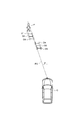
- the example shown in FIG. 3 is an example in which the six detection positions D1 to D6 of the target pedestrian P are fitted using the inclination ⁇ of the trajectory prediction vector PV, and is detected by the deflection of the host vehicle C.
- a lateral jump occurs between the position D3 and the detection position D4.
- the detection positions D4, D5, and D6 after the lateral position jump are excluded, and the detection positions D1, D2, and D3 are classified.
- the detection positions D1, D2, and D3 before the lateral position jump are excluded, and the detection positions D4, D5, and D6 are classified.
- the substantially H-shaped mark indicating the detection positions D1,... Indicates the detection range (horizontal width) by the length in the horizontal direction.
- the object may be moving at a constant speed in a certain moving direction, or may be changing the moving direction or speed.
- it is better to reflect the detection position after changing the moving direction or speed of the object in the prediction of the future movement trajectory of the object. Therefore, it is better to emphasize the detection position closer to the present in the history of detection positions of the object in the prediction of the future movement trajectory of the object. Therefore, when fitting is performed, the weight is increased for the detection position (latest detection position) closer to the present in the time in the history of detection positions of the target object, and the fitting is performed.
- the weighted least square method is used.
- the reason why the position where the strength of the vertical edge is strong is used as the detection position of the object will be described.
- the range in which the object is detected changes, and the center position of the detection range varies.
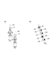
- the lateral width (detection range) W1 of the pedestrian P when the arm is swung back and forth and the arm are swung back and forth. This is different from the lateral width (detection range) W2 of the pedestrian P when not starting.
- the center position is around the front end of the body of the pedestrian P
- the width is W2
- the center position is around the center of the body of the pedestrian P. Therefore, as shown in FIG. 4B, the lateral center positions P1, P2,... Of the pedestrian P indicated by black triangle marks vary.
- the center position of the horizontal width or the end of the horizontal width
- the fitting and the movement trajectory are predicted based on the history of the detection positions that vary. As a result, the fitting cannot be performed with high accuracy, and the prediction accuracy of the movement trajectory is lowered.
- the position where the vertical edge strength is strong even in the area where the object is detected from the image is the location where the object is strong in the horizontal direction in the detection range (exist This is suitable as the position of the object. Therefore, when the detection position of the object is used for fitting or the like, the position having the strongest vertical edge strength in the detection range (especially the horizontal width) of the object is used as the detection position of the object.
- the position E1 where the vertical edge strength of the pedestrian P is the strongest when the arm is swung back and forth is around the center of the body of the pedestrian P, and the arm is swung back and forth.
- the position E2 where the vertical edge strength of the pedestrian P is the strongest when the pedestrian is not is also near the center of the pedestrian P. Moreover, as shown in FIG.4 (b), position E1, E2, ... with the strongest vertical edge intensity
- the removal of the abnormal value of the ground speed of the object will be described with reference to FIG.
- the trajectory prediction vector PV obtained from the ground speed becomes a vector including an error, and fitting is performed using the slope ⁇ including the error.
- the ground speed of the object is a jump value far from the previous value, the ground speed may be an abnormal value.
- the ground speed is a jump value from the previous value, there is a possibility that the ground speed has suddenly changed due to the actual acceleration or sudden deceleration of the object.
- the ground speed of the object is a jump value from the previous value and is far away from the moving speed obtained from the difference in the detected position of the object, the ground speed of the object is determined to be an abnormal value, and the trajectory prediction is performed. Not used for vector calculation.
- the ground speed Vp6 is a jump value from the previous value Vp5 among the ground speeds Vp1, Vp2,.
- the current value D6 does not change abruptly from the previous value D5 (the difference between the current value D6 and the previous value D5 is not large). Therefore, the ground speed Vp6 is determined to be an abnormal value and is not used.
- the countermeasure when the ground speed is judged as an abnormal value is explained.
- the speed obtained from the previous value of the ground speed or the difference between the current value of the detected position of the object and the previous value is used.
- the average value of an arbitrary number of ground speeds in the past is used when obtaining the trajectory prediction vector PV, the average value of the ground speeds is calculated without using the latest ground speed.
- the amount of steering of the own vehicle is large (when the own vehicle is not traveling straight)
- the own vehicle has more than a certain amount of steering turning or turning back
- the own vehicle turns due to the turning or turning back, and the traveling direction changes.
- the relative detection position of the object also changes greatly accordingly.
- the apparent shape of the object may change, and the detection accuracy of the ground speed of the object may be lowered. Therefore, when the amount of steering of the host vehicle is greater than or equal to a predetermined amount, calculation and fitting of the trajectory prediction vector PV (particularly, the inclination ⁇ ) is not performed.
- trajectory of a target object is estimated by the conventional method using all the detection positions of the history of the detection position of a target object.
- a movement trajectory is predicted using a difference between detection positions included in the history of detection positions, or a movement trajectory is predicted by performing linear regression on the detection position history.
- the collision prediction device 1 includes a stereo camera 10, a steering angle sensor 11, a yaw rate sensor 12, a wheel speed sensor 13, an alarm device 20, a collision avoidance support device 21, a seat belt control device 22, a seat control device 23, a brake control device 24, and A system ECU [Electronic Control Unit] 30 is provided.
- the stereo camera 10 corresponds to the object detection unit described in the claims
- the processing of the stereo camera 10 and the system ECU 30 corresponds to the speed acquisition unit described in the claims.
- Each process corresponds to a relative movement vector calculation unit, a classification unit, and a movement trajectory prediction unit described in the claims.
- the stereo camera 10 is composed of a pair of left and right cameras for photographing the front of the host vehicle and an image processing device.
- Each of the pair of left and right cameras of the stereo camera 10 captures images at regular time intervals (for example, every 1/30 seconds), and acquires a left image and a right image.
- the image processing apparatus of the stereo camera 10 performs object detection processing using the left and right images (stereo images), and when the object (target) can be detected, information on the object (for example, the stereo camera 10 (self The distance in the depth direction from the vehicle) to the object, the lateral position in the lateral direction, the lateral width and height of the object, and the shape of the object are acquired.
- This object detection method using a stereo image applies a conventional well-known technique, for example, performs a correlation calculation between stereo images, and uses a parallax obtained from the correlation calculation result to detect the object and image
- the stereo camera 10 transmits information on the presence / absence of the object and information on each object (for each target) to the system ECU 30 as a stereo camera signal when the object can be detected at regular time intervals.
- edge processing information on the vertical edge strength and the horizontal edge strength within the range detected for each object is also transmitted.
- the object to be detected by the stereo camera 10 has a certain size and height such as pedestrians, bicycles, vehicles, utility poles, traffic signs and the like as described above.
- processing is performed in a pixel unit coordinate system in the horizontal direction / vertical direction of an image captured by the camera, and object information is data in pixel units.
- an identification number is assigned to the detected target, and when the same target is detected at different times, the same identification number is assigned and the number of detections is counted. Information of these identification numbers and the number of detection times is also transmitted as stereo camera signals as information for each target.
- the steering angle sensor 11 is a sensor that detects the steering angle input to the steering wheel by the driver.
- the steering angle sensor 11 detects the steering angle at regular intervals, and transmits the detected steering angle to the system ECU 30 as a steering angle signal.
- the yaw rate sensor 12 is a sensor that detects the yaw rate acting on the host vehicle.
- the yaw rate sensor 12 detects the yaw rate at regular intervals, and transmits the detected yaw rate to the system ECU 30 as a yaw rate signal.
- the wheel speed sensor 13 is a sensor that is provided on each of the four wheels of the vehicle and detects the rotational speed of the wheel (number of pulses corresponding to the rotation of the wheel).
- the wheel speed sensor 13 detects the number of wheel rotation pulses at regular time intervals, and transmits the detected wheel rotation pulse number to the system ECU 30 as a wheel speed signal.
- the system ECU 30 calculates the wheel speed from the number of rotation pulses of each wheel, and calculates the vehicle body speed (vehicle speed) from the wheel speed of each wheel.
- the warning device 20 is a device for warning the driver of the host vehicle.
- Alarms include buzzer (alarm sound) output, alarm message audio output and display, and the like.
- the alarm device 20 receives an alarm control signal from the system ECU 30, the alarm device 20 outputs an alarm based on the alarm control signal.
- the collision avoidance assistance device 21 is a device for avoiding collision and reducing impact caused by collision by steering control (automatic steering, steering assist, etc.).
- the collision avoidance assistance device 21 receives a collision avoidance control signal from the system ECU 30, it performs steering control based on the collision avoidance control signal.
- the seat belt control device 22 is a device for reducing the collision damage by controlling the tightening force of the seat belt.
- the seat belt control device 22 receives the seat belt control signal from the system ECU 30, the seat belt control device 22 controls the tightening force of the seat belt based on the seat belt control signal.
- the sheet control device 23 is a device for reducing the collision damage by controlling the position and posture of the sheet.
- the seat control device 23 controls the position and posture of the seat based on the seat control signal.
- the brake control device 24 is a device for mitigating collision avoidance and impact caused by collision by brake control (automatic stop, automatic deceleration, brake assist, etc.).
- brake control automatic stop, automatic deceleration, brake assist, etc.
- the brake control device 24 performs brake control based on the brake control signal.
- the system ECU 30 is an electronic control unit that includes a CPU [Central Processing Unit], ROM [Read Only Memory], RAM [Random Access Memory], and the like, and performs overall control of the collision prediction apparatus 1.
- the system ECU 30 receives a stereo camera signal from the stereo camera 10 at regular intervals. Further, the system ECU 30 receives detection signals from the sensors 11, 12, and 13. Then, the system ECU 30 loads the application program stored in the ROM using the stereo camera signal and each detection signal into the RAM and executes it by the CPU (the vehicle trajectory prediction process, the ground control).
- the trajectory prediction vector calculation process in the system ECU 30 corresponds to the relative movement vector calculation unit described in the claims
- the fitting process corresponds to the classification unit described in the claims
- the straight object prediction process is charged. This corresponds to the movement trajectory prediction unit described in the range.
- the ground speed detection process in the stereo camera 10 and the system ECU 30 corresponds to a speed acquisition unit described in the claims.
- the system ECU 30 when the same target (object) is detected at least twice in succession by the stereo camera 10, the movement trajectory of the object is predicted, and the collision between the object and the host vehicle is performed. Make a decision.
- the system ECU 30 stores a sufficient number of pieces of position information necessary for prediction for each object when the target (object) is detected by the stereo camera 10. To keep (record).
- the target (object) when the target (object) is detected with the stereo camera 10, it processes for every object.
- the system ECU 30 performs processing in a coordinate system of length units in the horizontal direction (x direction) / distance direction (y direction) (for example, several tens of centimeters, several centimeters), and is obtained from the stereo camera 10.
- Data in pixel units in the horizontal / vertical direction of the image is converted into data in length units in the horizontal / distance direction.
- Processing may be performed in a coordinate system in units of pixels in the horizontal / vertical direction of the image without performing such conversion.
- the lateral component is used when handling the detection position and speed of the object. Only the detection position and speed may be used.
- the vehicle trajectory prediction process will be described.
- the system ECU 30 predicts the future movement trajectory of the host vehicle from the history of the vehicle speed, yaw rate, and steering angle of the host vehicle.
- a conventional well-known prediction method is applied as a method of predicting the movement trajectory.
- the system ECU 30 determines the difference between the current value of the detected position of the target object and the position of the fixed object on the road (the relative value of the current value of the detected position with respect to the fixed object).
- Vector a difference between the previous value of the detection position of the object and the position of the same fixed object on the road (relative vector of the previous value of the detection position with reference to the fixed object).
- this fixed object for example, a point with a large luminance gradient obtained by edge processing of an image around the own vehicle (a boundary of a white line drawn on the road surface, a road joint, etc.), a roadside object (electric pole, traffic sign, etc.) Etc.).
- the system ECU 30 calculates the ground speed of the object by dividing the movement amount of the movement vector by the update time.
- the system ECU 30 calculates a change amount (steering amount) of the steering angle for a predetermined time, and determines whether the steering amount is equal to or greater than a steering threshold.
- the predetermined time is set in advance by adaptation and is, for example, an update time of one step.
- the steering threshold is a steering amount for determining steering of the host vehicle (when the host vehicle is not traveling straight) that is clearly different from the shake or deflection of the host vehicle, and is set in advance by adaptation.
- the system ECU 30 proceeds to the object trajectory prediction process during steering, and when the steering amount is less than the steering threshold (when the host vehicle is traveling straight ahead). ) Shifts to an abnormal value removal process.
- the steering object trajectory prediction process will be described.
- the system ECU 30 predicts the future movement trajectory of the object using the history of the detection position of the object by a conventional prediction method.
- the abnormal value removal process (filtering process) will be described.
- the system ECU 30 determines whether or not the ground speed of the object detected by the ground speed detection process is only once. When the ground speed is detected only once, the system ECU 30 uses the ground speed in the following processing. When the ground speed is detected twice or more, the system ECU 30 determines whether or not the absolute value of the difference between the current value and the previous value of the ground speed is equal to or greater than the first threshold value.
- the first threshold value is a threshold value for determining whether or not the ground speed of the object is a jump value from the previous value, and is set in advance by adaptation.
- the system ECU 30 calculates the speed by dividing the difference between the current value of the detected position of the object and the previous value by the update time. Then, it is determined whether or not the absolute value of the difference between the speed and the current value of the ground speed is greater than or equal to the second threshold value.
- the second threshold value is a threshold value for determining whether or not the ground speed of the object is a value away from the speed obtained from the difference between the detected positions of the object, and is set in advance by adaptation.
- the system ECU 30 When this determination is equal to or greater than the second threshold (when the current value of the ground speed is a value that is different from the speed due to the difference in the detection position), the system ECU 30 does not use the current value of the ground speed as the ground speed in the following processing. . At this time, for example, the previous value of the ground speed is used as the ground speed.
- the system ECU 30 uses the current value of the ground speed as the ground speed in the following processing. Note that the first threshold value and the second threshold value may be the same value or different values.
- the trajectory prediction vector calculation process will be described.
- the system ECU 30 uses the vehicle speed Vc of the host vehicle and the ground speed Vp (lateral component (x-axis component): Vpx, distance direction component (y-axis component): Vpy) of the object,
- the inclination ⁇ of the trajectory prediction vector PV is calculated.
- the inclination ⁇ of the trajectory prediction vector PV necessary for the fitting process is directly calculated, but the inclination ⁇ may be calculated after obtaining the trajectory prediction vector PV. If the speed Vpy in the distance direction of the object is negligibly small compared to the vehicle speed Vc of the host vehicle, the calculation may be performed excluding Vpy. Also, the unit and the direction of the code are converted as necessary.
- a majority method is used.
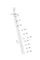
- FIGS. 7 and 8 an example in which fitting is performed on 10 detection positions D1 to D10 as a history of detection positions of the object will be described.
- the detection position D10 is the latest detection position
- the detection position D1 is the oldest detection position.
- a weight is set for each of the detection positions D1 to D10, a maximum of 7 is set as the weight for the latest detection position D10, and a smaller value is set for the weight as the past detection position is reached.
- the host vehicle is deflected between the detection position D3 and the detection position D4 and a lateral position jump occurs.
- the detection position D6 is an outlier due to sensor noise.
- the system ECU 30 sequentially selects the detection positions Di from the detection positions D1 to D10 held (recorded) in the RAM, and performs the following processing for all the detection positions D1 to D10.
- a straight line having an inclination ⁇ passing through the detection position Di is calculated.
- the system ECU 30 calculates each parallel line with a predetermined interval on both the left and right sides with the straight line as the center, and sets a voting range composed of the left and right parallel lines.
- This predetermined interval is an interval at which the detection position of the lateral position jump can be excluded when the lateral position jump due to the shake or deflection of the host vehicle has occurred, and the detection position in the object detection by the stereo camera 10 This is the interval at which noise values (outliers) can be excluded.
- the predetermined interval is set in advance by adaptation. Then, the system ECU 30 extracts detection positions that fall within the voting range from the detection positions D1 to D10. Further, the system ECU 30 integrates the weights of the detected detection positions, and uses the integrated value as a voting point.
- the system ECU 30 compares the voting points of all the detection positions D1 to D10, and selects the straight line of the detection position of the largest voting point.
- straight lines at a plurality of detection positions it is assumed that the selected plurality of straight lines are substantially the same straight line.
- the final straight line is a straight line at the latest detection position.
- an average straight line of a plurality of selected detection positions may be used.
- FIG. 7 shows an example with respect to the detection position D1, and a straight line L1 having an inclination ⁇ passing through the detection position D1 and parallel lines L2 and L3 are calculated on the left and right sides thereof, and the voting composed of the parallel line L2 and the parallel line L3 is calculated.
- a range is set.
- the detection position D1, the detection position D2, and the detection position D3 are extracted as detection positions that fall within the voting range, and four points are calculated as voting points.
- the detection position is a detection position that falls within a voting range centered on a straight line having an inclination ⁇ passing through the detection position D10 (similarly, the detection position D4, the detection position D5, the detection position D7, the detection position D8, and the detection position D9).
- detection position D5 detection position D7, detection position D8, detection position D9, and detection position D10 are extracted, and 27 points are calculated as voting points, and this is the largest voting point. Therefore, for example, a straight line having an inclination ⁇ passing through the detection position D10 is selected as the final straight line.
- each detection position Di is classified into each group including a plurality of detection positions that fall within the voting range of the detection position Di.
- this group includes both the detection positions before and after the lateral position jump. There are few (or none).
- each group includes all detection positions in the history of detection positions except for outliers.
- the group with the largest vote point may be the group that best fits (matches) the straight line having the inclination ⁇ , and the plurality of groups may be the best fit group.
- a straight line having an inclination ⁇ passing through the detection position finally selected in the fitting process is predicted as a movement locus of the object.
- This movement trajectory corresponds to a trajectory predicted from a plurality of detection positions included in a group that best fits a straight line having an inclination ⁇ .
- each surface of the host vehicle front surface, rear surface, right side surface, left side surface
- This partitioning is preset by matching.
- the movement trajectory and target of the host vehicle are determined based on the movement trajectory of the host vehicle predicted by the host vehicle trajectory prediction process and the target object trajectory predicted by the steering object trajectory prediction process or the straight object trajectory prediction process.
- the collision probability accumulation process will be described.
- the system ECU 30 calculates the collision probability of each section around the predicted collision position. For example, the collision probability is calculated in a normal distribution with the predicted collision position as the center, or a high collision probability is calculated only for the predicted collision position. Further, the system ECU 30 adds the calculated collision probability to the previous integrated value for each section of the predicted collision position, and integrates the collision probability.
- the collision determination process will be described.
- the system ECU 30 determines whether or not the collision probability integrated value is greater than or equal to the set collision determination threshold for each collision position section on each surface of the host vehicle (only the section in which the integrated value is updated in the collision probability integration process). Determine whether.
- the collision determination threshold value is a threshold value for determining whether or not the own vehicle may collide with the target object based on the integrated value of the collision probability for each predicted collision position, and is set in advance by adaptation through experiments or simulations. The Then, the system ECU 30 determines that there is a possibility of collision (high possibility) when the integrated value of the collision probability is equal to or greater than the collision determination threshold value, and when the integrated value of the collision probability is less than the collision determination threshold value. It is determined that there is no possibility of collision (low possibility).
- TTC Time To Collision
- FIG. 9 is a flowchart showing an operation flow in the collision prediction apparatus according to the present embodiment.
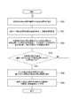
- FIG. 10 is a flowchart showing the flow of abnormal value removal processing in the flowchart of FIG.
- FIG. 11 is a flowchart showing the flow of the fitting process / trajectory object trajectory prediction process in the flowchart of FIG. 9.
- the collision prediction apparatus 1 repeatedly performs the following operation at regular intervals.
- the stereo camera 10 picks up images with a pair of left and right cameras, performs object detection processing using the left and right images (stereo images), and detects the position of the object (target). Information (distance, horizontal position), width, etc. are acquired (S1).
- the stereo camera 10 detects the presence / absence information of the target object or the target object
- the stereo camera 10 transmits a stereo camera signal including position information for each target object to the system ECU 30.
- the system ECU 30 receives this stereo camera signal, and when there is an object, acquires position information and the like for each object, and holds (records) the position information and the like in the RAM. If there is no object, the current process ends.
- the steering angle sensor 11 detects the steering angle and transmits a steering angle signal to the system ECU 30.
- the system ECU 30 receives this steering angle signal and acquires the steering angle.
- the yaw rate sensor 12 detects the yaw rate and transmits a yaw rate signal to the system ECU 30.
- the system ECU 30 receives this yaw rate signal and acquires the yaw rate.
- the wheel speed sensor 13 of each wheel detects the number of rotation pulses of the wheel and transmits a wheel speed signal to the system ECU 30.
- the system ECU 30 receives a wheel speed signal for each wheel, calculates a wheel speed from the number of rotation pulses of each wheel, and calculates a vehicle speed (own vehicle speed) from the wheel speed of each wheel.
- the system ECU 30 predicts the movement trajectory of the host vehicle from the history of the vehicle speed, yaw rate, and steering angle of the host vehicle (S2). Further, the system ECU 30 calculates, for each object, a relative vector of the current value of the detection position of the object relative to the fixed object and a relative vector of the previous value of the detection position based on the same fixed object. A movement vector from the previous value of the detection position to the current value is calculated from the two relative vectors, and the ground speed of the object is calculated (detected) from the movement vector (S3).
- the system ECU 30 determines whether or not the steering amount (addition amount, return amount) of the host vehicle is greater than or equal to the steering threshold (S4). If it is determined in S4 that the steering amount is equal to or greater than the steering threshold (the host vehicle is turning), the system ECU 30 determines the movement trajectory of the object from the history of the detection position of the object by the conventional trajectory prediction unit for each object. Predict (S5).
- the system ECU 30 removes an abnormal value (filtering) for the ground speed detected in S3 for each object (S6). Specifically, as shown in the flowchart of FIG. 10, the system ECU 30 determines whether or not the ground speed is detected once (S20). If it is determined in S20 that the time is once, the system ECU 30 uses the ground speed detected this time as the ground speed in the following processing (S21). If it is determined at S20 that the number is twice or more, the system ECU 30 determines whether the absolute value of the difference between the currently detected ground speed and the previous value of the ground speed is equal to or greater than the first threshold (S22).
- the system ECU 30 uses the ground speed detected this time as the ground speed in the following processing (S25). If it is determined in S22 that the value is equal to or greater than the first threshold, the system ECU 30 calculates the difference between the current value of the ground speed detected this time and the current value of the detected position of the target object (particularly the horizontal position) and the previous value by the update time. It is determined whether or not the absolute value of the difference from the speed is greater than or equal to a second threshold value (S23). If it is determined in S24 that the second threshold value is exceeded, the system ECU 30 uses the previous value of the ground speed as the ground speed in the following processing (S24).
- the system ECU 30 uses the ground speed detected this time as the ground speed in the following processing (S25). Then, the system ECU 30 holds the current detection position of the object and the ground speed as the previous values (S26).
- the system ECU 30 calculates the inclination ⁇ of the trajectory prediction vector for each object using the vehicle speed of the host vehicle and the ground speed of the object (S7). Then, the system ECU 30 performs fitting with a straight line having an inclination ⁇ with respect to the history of detection positions of the target object held in the RAM for each target object (S8), and uses the most fitted straight line as the movement trajectory of the target object. Predict (S9). Specifically, as shown in the flowchart of FIG. 11, the system ECU 30 sequentially selects the detection positions Di from the history of the detection positions of the objects (S30).
- the system ECU 30 calculates a straight line passing through the detection position Di with the inclination ⁇ , and sets a voting range centered on the straight line (S31). Further, the system ECU 30 extracts detection positions that fall within the voting range of the detection position Di from the history of detection positions of the target object, integrates the weights of the extracted detection positions, and calculates voting points at the detection position Di. (S32). The system ECU 30 determines whether or not the processing for all the detection positions included in the history of detection positions of the object has been completed (S33). If it is determined in S33 that the processing for all the detection positions has not been completed, the system ECU 30 returns to the process of S30 and selects the next detection position.
- the system ECU 30 compares the voting points of all the detected positions and selects the straight line of the detected position of the largest voting point (S34). Then, the system ECU 30 predicts a straight line having an inclination ⁇ passing through the selected detection position as a movement locus of the object (S35).
- the system ECU 30 predicts, for each object, a position where it collides with the own vehicle from the movement locus of the own vehicle and the movement locus of the object (S10). And in system ECU30, a collision probability is integrated
- the system ECU 30 determines, for each target object, whether or not there is a possibility of collision between the host vehicle and the target object, based on whether or not the integrated value of the collision probability at each predicted collision position is greater than or equal to the collision determination threshold value. (S12). If it is determined in S12 that the threshold is less than the collision determination threshold (no possibility of collision), the system ECU 30 ends the current process. On the other hand, if it is determined in S12 that the collision determination threshold value is exceeded (there is a possibility of a collision), the system ECU 30 avoids the collision and reduces the damage due to the collision for each target object in order to avoid a collision margin (TTC).
- TTC collision margin
- a control signal is transmitted to a corresponding device among the alarm device 20, the collision avoidance support device 21, the seat belt control device 22, the seat control device 23, and the brake control device 24 (S13).
- the alarm device 20 receives an alarm control signal from the system ECU 30, the alarm device 20 outputs an alarm based on the alarm control signal.
- the collision avoidance assistance device 21 receives a collision avoidance control signal from the system ECU 30, it performs steering control based on the collision avoidance control signal.
- the seat belt control device 22 When the seat belt control device 22 receives a seat belt control signal from the system ECU 30, the seat belt control device 22 controls the tightening force of the seat belt based on the seat belt control signal. When the seat control signal is received from the system ECU 30, the seat control device 23 controls the position and orientation of the seat based on the seat control signal. When the brake control device 24 receives a brake control signal from the system ECU 30, the brake control device 24 performs brake control based on the brake control signal.
- the movement trajectory of the target object is predicted by fitting the history of the relative detection positions of the target object with a straight line of the inclination of the trajectory prediction vector based on the ground speed of the target object. Even when a lateral position jump occurs in the history of the detection position of the object due to the shake or deflection of the host vehicle, the movement trajectory of the object can be predicted with high accuracy from the history of the detection position of the object.
- the collision prediction apparatus 1 by using the position having the strongest vertical edge strength as the detection position of the object, it is possible to suppress the variation in the history of the detection position of the object, and to make the movement locus of the object more accurate. Can be predicted. This is particularly effective for an object whose shape changes, such as a pedestrian. Further, according to the collision prediction apparatus 1, by performing fitting by increasing the weight of a position closer to the current position in the history of detection positions of the object, the movement trajectory of the object can be more accurately determined. Can be predicted. In addition, according to the collision prediction apparatus 1, when the ground speed of the target object is an abnormal value, the ground speed is not used for calculating the trajectory prediction vector (especially, the slope), so that it is possible to suppress a decrease in accuracy of the trajectory prediction vector. Thus, it is possible to suppress a decrease in the prediction accuracy of the movement locus.
- the movement trajectory of an object is predicted, the possibility of a collision with the host vehicle is determined using the movement trajectory of the object, and when there is a possibility, collision avoidance and collision damage reduction are performed.
- a device that performs support it may be applied to other driving support devices that perform other support using the predicted movement trajectory of the object, or movement that only predicts the movement trajectory of the object You may apply to a locus
- a stereo camera is applied as an external sensor for detecting an object around the host vehicle.
- an image sensor using a monocular camera which can detect the distance and lateral position of an object with a single eye
- a laser radar Other external sensors such as a radar sensor such as a millimeter wave radar may be used.
- a stereo camera as an external sensor may be fused with a radar sensor or the like as an operation condition of the device.
- the detection is made from the own vehicle using the stereo camera of the external sensor, but the detection is made from the own vehicle using another external sensor such as a radar sensor. It is good also as a structure which carries out, and the structure (for example, pedestrian in case a target object is a pedestrian) which detects using the device (mobile phone, smart phone, etc.) which a target object detects, and receives by communication between target objects Configuration that receives the speed detected by the device carried by the vehicle by inter-vehicle communication), or the configuration that detects by road-side infrastructure (fixed point camera, radar, etc.) and receives by road-to-vehicle communication with the road-side infrastructure It is good. Note that the configuration for detecting the object and the configuration for acquiring the ground speed of the object are not limited to the same sensor or the same ECU, and the configuration is not limited.
- alarm, steering, seat belt, seat, and brake devices are shown as devices to be activated when there is a possibility of a collision.
- one or more of these devices may be used.
- other devices actuators
- a voting range centered on a straight line of the inclination ⁇ passing through the detection position is set, and the fitting is performed by majority vote of the voting points based on the detection position entering the voting range.
- the least square method or the like is used.
- the fitting may be performed by other methods.
- the weight is set to the detection position of the object to perform the fitting, but the fitting may be performed without setting the weight.
- the position where the vertical edge intensity is the strongest is used as the detection position of the object.
- the vertical edge intensity is not used, but other positions such as the center position of the detection range of the detected object are used. It is good also as a structure using a position.
- the shape does not change particularly during movement, so the vertical edge strength need not be used.
- the target is obtained by performing greater weighting as the vertical edge strength is larger. There is a technique for facilitating use as an object detection position.
- the ground speed abnormal value removal is performed, but when the ground speed detection accuracy is good and the ground speed is assumed to have no abnormal value, the abnormal value removal is not performed. Also good.
- the present invention is mounted on a vehicle and can be used for movement trajectory prediction for predicting a movement trajectory of an object from a history of detection positions of the object around the vehicle.
- SYMBOLS 1 ... Collision prediction apparatus, 10 ... Stereo camera, 11 ... Steering angle sensor, 12 ... Yaw rate sensor, 13 ... Wheel speed sensor, 20 ... Alarm device, 21 ... Collision avoidance support device, 22 ... Seat belt control device, 23 ... Seat Control device, 24 ... brake control device, 30 ... system ECU.
Landscapes
- Engineering & Computer Science (AREA)
- Physics & Mathematics (AREA)
- Automation & Control Theory (AREA)
- Transportation (AREA)
- Mechanical Engineering (AREA)
- General Physics & Mathematics (AREA)
- Theoretical Computer Science (AREA)
- Computer Vision & Pattern Recognition (AREA)
- Multimedia (AREA)
- Human Computer Interaction (AREA)
- Chemical & Material Sciences (AREA)
- Combustion & Propulsion (AREA)
- Data Mining & Analysis (AREA)
- Geometry (AREA)
- Artificial Intelligence (AREA)
- Life Sciences & Earth Sciences (AREA)
- Bioinformatics & Cheminformatics (AREA)
- Bioinformatics & Computational Biology (AREA)
- Evolutionary Biology (AREA)
- Evolutionary Computation (AREA)
- General Engineering & Computer Science (AREA)
- Traffic Control Systems (AREA)
- Image Analysis (AREA)
Abstract
Description
Claims (6)
- 車両周辺の対象物の移動軌跡を予測する移動軌跡予測装置であって、
車両周辺の対象物の位置を取得する対象物検出部と、
前記対象物の対地速度を取得する速度取得部と、
前記車両の速度情報と、前記速度取得部で取得した前記対象物の対地速度とを用いて前記車両からの前記対象物の相対移動ベクトルを算出する相対移動ベクトル算出部と、
前記対象物検出部で取得した前記対象物の移動軌跡における位置を記録し、当該記録された位置を前記相対移動ベクトル算出部で算出した相対移動ベクトルに基づいて、複数のグループに分類する分類部と、
前記分類部で分類したグループのうちの少なくとも1つのグループに含まれる前記対象物の複数の位置に基づいて当該対象物の移動軌跡を予測する移動軌跡予測部と、
を備えることを特徴とする移動軌跡予測装置。 - 前記対象物検出部は、カメラで撮像した画像に対するエッジ処理によって前記対象物の検出を行い、
前記分類部は、前記記録された対象物の位置の分類において、前記画像における縦エッジ強度が強い位置である場合程、当該位置の前記対象物の位置としての利用を促進することを特徴とする請求項1に記載の移動軌跡予測装置。 - 前記車両の操舵量が所定量以上の場合には前記分類部での分類を行わないことを特徴とする請求項1又は請求項2に記載の移動軌跡予測装置。
- 前記分類部は、前記記録された対象物の位置のうち時間的に現在に近い位置である場合程、当該位置の重みを大きくして分類を行うことを特徴とする請求項1~請求項3のいずれか1項に記載の移動軌跡予測装置。
- 前記相対移動ベクトル算出部は、対地速度の前回値との差が第1閾値以上かつ前記対象物の位置の差分から求められる速度との差が第2閾値以上の前記対象物の対地速度を相対移動ベクトルの算出に用いないことを特徴とする請求項1~請求項4のいずれか1項に記載の移動軌跡予測装置。
- 車両周辺の対象物の移動軌跡を予測する移動軌跡予測方法であって、
車両周辺の対象物の位置を取得する対象物検出ステップと、
前記対象物の対地速度を取得する速度取得ステップと、
前記車両の速度情報と、前記速度取得ステップで取得した前記対象物の対地速度とを用いて前記車両からの前記対象物の相対移動ベクトルを算出する相対移動ベクトル算出ステップと、
前記対象物検出ステップで取得した前記対象物の移動軌跡における位置を記録し、当該記録された位置を前記相対移動ベクトル算出ステップで算出した相対移動ベクトルに基づいて、複数のグループに分類する分類ステップと、
前記分類ステップで分類したグループのうちの少なくとも1つのグループに含まれる前記対象物の複数の位置に基づいて当該対象物の移動軌跡を予測する移動軌跡予測ステップと、
を含むことを特徴とする移動軌跡予測方法。
Priority Applications (5)
| Application Number | Priority Date | Filing Date | Title |
|---|---|---|---|
| DE112013007129.0T DE112013007129B4 (de) | 2013-05-31 | 2013-05-31 | Bewegungstrajektorienvorhersagevorrichtung und Bewegungstrajektorienvorhersageverfahren |
| US14/892,468 US9975550B2 (en) | 2013-05-31 | 2013-05-31 | Movement trajectory predicting device and movement trajectory predicting method |
| PCT/JP2013/065198 WO2014192137A1 (ja) | 2013-05-31 | 2013-05-31 | 移動軌跡予測装置及び移動軌跡予測方法 |
| CN201380076974.1A CN105324275B (zh) | 2013-05-31 | 2013-05-31 | 移动轨迹预测装置和移动轨迹预测方法 |
| JP2015519576A JP5939357B2 (ja) | 2013-05-31 | 2013-05-31 | 移動軌跡予測装置及び移動軌跡予測方法 |
Applications Claiming Priority (1)
| Application Number | Priority Date | Filing Date | Title |
|---|---|---|---|
| PCT/JP2013/065198 WO2014192137A1 (ja) | 2013-05-31 | 2013-05-31 | 移動軌跡予測装置及び移動軌跡予測方法 |
Publications (1)
| Publication Number | Publication Date |
|---|---|
| WO2014192137A1 true WO2014192137A1 (ja) | 2014-12-04 |
Family
ID=51988205
Family Applications (1)
| Application Number | Title | Priority Date | Filing Date |
|---|---|---|---|
| PCT/JP2013/065198 Ceased WO2014192137A1 (ja) | 2013-05-31 | 2013-05-31 | 移動軌跡予測装置及び移動軌跡予測方法 |
Country Status (5)
| Country | Link |
|---|---|
| US (1) | US9975550B2 (ja) |
| JP (1) | JP5939357B2 (ja) |
| CN (1) | CN105324275B (ja) |
| DE (1) | DE112013007129B4 (ja) |
| WO (1) | WO2014192137A1 (ja) |
Cited By (12)
| Publication number | Priority date | Publication date | Assignee | Title |
|---|---|---|---|---|
| CN105857307A (zh) * | 2015-02-07 | 2016-08-17 | 赫拉胡克公司 | 用于至少部分独立地控制机动车辆的方法 |
| JP2017194926A (ja) * | 2016-04-22 | 2017-10-26 | 株式会社デンソー | 車両制御装置、車両制御方法 |
| DE102016215314A1 (de) | 2016-08-17 | 2018-02-22 | Bayerische Motoren Werke Aktiengesellschaft | Fahrerassistenzsystem, Fortbewegungsmittel und Verfahren zur Prädiktion einer Verkehrssituation |
| CN108367683A (zh) * | 2015-12-18 | 2018-08-03 | 沃尔沃卡车集团 | 一种控制使用电力道路系统的车辆中的安全系统的方法 |
| JP2018136240A (ja) * | 2017-02-23 | 2018-08-30 | 三菱電機株式会社 | 推定装置、推定方法、推定装置を備えた追尾装置、および推定方法を備えた追尾方法 |
| CN111788571A (zh) * | 2018-03-15 | 2020-10-16 | 蓝色视觉实验室英国有限公司 | 车辆跟踪 |
| CN112364492A (zh) * | 2020-10-28 | 2021-02-12 | 东北大学 | 薄带连铸活套的控制方法及装置 |
| CN113053112A (zh) * | 2021-03-10 | 2021-06-29 | 北京星云互联科技有限公司 | 车辆轨迹预测方法、车辆预测轨迹分析方法、装置及车辆 |
| JP2021155024A (ja) * | 2020-02-11 | 2021-10-07 | トヨタ リサーチ インスティテュート,インコーポレイティド | 歩行者の動きを予測するためのシステムおよび方法 |
| WO2023058559A1 (ja) * | 2021-10-07 | 2023-04-13 | 株式会社デンソー | 情報処理装置、物体追跡装置、追跡方法、プログラム |
| WO2023238735A1 (ja) * | 2022-06-07 | 2023-12-14 | ソニーセミコンダクタソリューションズ株式会社 | 情報処理装置、情報処理方法、プログラム |
| WO2024241428A1 (ja) * | 2023-05-22 | 2024-11-28 | 日立Astemo株式会社 | 車両制御装置 |
Families Citing this family (79)
| Publication number | Priority date | Publication date | Assignee | Title |
|---|---|---|---|---|
| WO2014174637A1 (ja) * | 2013-04-25 | 2014-10-30 | トヨタ自動車株式会社 | 運転支援装置及び運転支援方法 |
| JP6049542B2 (ja) * | 2013-05-31 | 2016-12-21 | 日立オートモティブシステムズ株式会社 | 車両制御システム |
| DE102013222586A1 (de) * | 2013-11-07 | 2015-05-07 | Robert Bosch Gmbh | Verfahren zur Vermeidung einer Kollision eines Kraftfahrzeugs mit einem falschfahrenden Fahrzeug und Steuer- und Erfassungseinrichtung für ein Kraftfahrzeug zur Vermeidung einer Kollision des Kraftfahrzeugs mit einem falschfahrenden Fahrzeug |
| JP6441616B2 (ja) * | 2014-08-29 | 2018-12-19 | 株式会社ゼンリン | 位置特定装置、運転支援装置および制御プログラム |
| DE102014219148A1 (de) * | 2014-09-23 | 2016-03-24 | Robert Bosch Gmbh | Verfahren und Vorrichtung zum Erstellen eines Bewegungsmodells eines Straßenverkehrsteilnehmers |
| KR101628503B1 (ko) * | 2014-10-27 | 2016-06-08 | 현대자동차주식회사 | 운전자 보조장치 및 그 작동 방법 |
| KR101637716B1 (ko) * | 2014-11-03 | 2016-07-07 | 현대자동차주식회사 | 차량의 장애물 위치 인식 장치 및 방법 |
| EP3018010B1 (en) * | 2014-11-06 | 2018-01-10 | Volvo Car Corporation | Method for controlling a time of activation of a reversible restraint system in a vehicle |
| DE102015202099A1 (de) * | 2015-02-06 | 2016-08-11 | Bayerische Motoren Werke Aktiengesellschaft | Verarbeiten von Sensordaten für ein Fahrerassistenzsystem |
| US11167755B2 (en) | 2015-02-07 | 2021-11-09 | Hella Kgaa Hueck & Co. | Method for at least partially automatically controlling a motor vehicle |
| US9881477B2 (en) * | 2015-02-27 | 2018-01-30 | Elwha Llc | Device having a sensor for sensing an object and a communicator for coupling the sensor to a determiner for determining whether a subject may collide with the object |
| KR101714145B1 (ko) * | 2015-04-09 | 2017-03-08 | 현대자동차주식회사 | 주변차량 식별 장치 및 그 방법 |
| US10407047B2 (en) * | 2015-12-07 | 2019-09-10 | Magna Electronics Inc. | Vehicle control system with target vehicle trajectory tracking |
| JP2017117344A (ja) * | 2015-12-25 | 2017-06-29 | 株式会社デンソー | 走行支援装置 |
| EP3954969A1 (en) * | 2015-12-25 | 2022-02-16 | Pioneer Corporation | Distance estimation device, distance estimation method and program |
| JP6330825B2 (ja) * | 2016-01-26 | 2018-05-30 | トヨタ自動車株式会社 | 車両用衝突回避支援システム |
| DE102016202594A1 (de) * | 2016-02-19 | 2017-08-24 | Robert Bosch Gmbh | Verfahren und Vorrichtung zum Interpretieren einer Fahrzeugumgebung eines Fahrzeugs sowie Fahrzeug |
| JP6531689B2 (ja) * | 2016-03-22 | 2019-06-19 | 株式会社デンソー | 移動軌跡検出装置、移動物体検出装置、移動軌跡検出方法 |
| JP6508114B2 (ja) | 2016-04-20 | 2019-05-08 | トヨタ自動車株式会社 | 移動体の自動運転制御システム |
| DE102016209556A1 (de) * | 2016-06-01 | 2017-12-07 | Robert Bosch Gmbh | Verfahren zum Bereitstellen einer Information bezüglich eines Fußgängers in einem Umfeld eines Fahrzeugs und Verfahren zum Steuern eines Fahrzeugs |
| US10089875B2 (en) * | 2016-09-06 | 2018-10-02 | Delphi Technologies, Inc. | Automated vehicle cross-traffic detection system |
| CN106525033A (zh) * | 2016-09-22 | 2017-03-22 | 深圳市元征科技股份有限公司 | 一种行车轨迹的确定方法及其装置 |
| JP6577926B2 (ja) * | 2016-09-26 | 2019-09-18 | 本田技研工業株式会社 | 走行支援装置及び走行支援方法 |
| KR101967305B1 (ko) * | 2016-10-14 | 2019-05-15 | 주식회사 만도 | 차량의 보행자 인식 방법 및 차량의 보행자 인식 시스템 |
| US10248872B2 (en) * | 2016-10-19 | 2019-04-02 | Texas Instruments Incorporated | Estimation of time to collision in a computer vision system |
| CN106571064A (zh) * | 2016-11-10 | 2017-04-19 | 深圳市元征软件开发有限公司 | 基于路边单元的行人监测方法及装置 |
| WO2018116669A1 (ja) * | 2016-12-20 | 2018-06-28 | パイオニア株式会社 | 事故判定装置 |
| US10268200B2 (en) * | 2016-12-21 | 2019-04-23 | Baidu Usa Llc | Method and system to predict one or more trajectories of a vehicle based on context surrounding the vehicle |
| US10459441B2 (en) * | 2016-12-30 | 2019-10-29 | Baidu Usa Llc | Method and system for operating autonomous driving vehicles based on motion plans |
| FR3062721A1 (fr) * | 2017-02-03 | 2018-08-10 | Jd Recherche & Innovation | Procede de traitement de donnees dynamiques de geolocalisation pour la protection d’usagers vulnerables par rapport a des vehicules en mouvement |
| EP3364211B1 (en) * | 2017-02-21 | 2022-08-17 | Continental Autonomous Mobility Germany GmbH | Method and device for detecting a possible collision, and vehicle |
| FR3063265B1 (fr) * | 2017-02-28 | 2019-04-05 | Renault S.A.S | Dispositif de controle de trajectoire d un vehicule |
| CN110462684B (zh) * | 2017-04-10 | 2023-08-01 | 赫尔实验室有限公司 | 对对象移动进行隐式预测的系统、计算机可读介质与方法 |
| JP6812894B2 (ja) | 2017-04-24 | 2021-01-13 | トヨタ自動車株式会社 | 周辺監視装置 |
| US11190944B2 (en) | 2017-05-05 | 2021-11-30 | Ball Aerospace & Technologies Corp. | Spectral sensing and allocation using deep machine learning |
| WO2018212538A1 (en) | 2017-05-16 | 2018-11-22 | Samsung Electronics Co., Ltd. | Electronic device and method of detecting driving event of vehicle |
| KR102060662B1 (ko) * | 2017-05-16 | 2019-12-30 | 삼성전자주식회사 | 차량의 주행 이벤트를 검출하는 전자 장치 및 방법 |
| CN107200016B (zh) * | 2017-05-26 | 2019-11-08 | 重庆长安汽车股份有限公司 | 道路自适应预测方法及采用该方法的车辆系统 |
| EP3422046B1 (en) * | 2017-06-30 | 2021-04-28 | Veoneer Sweden AB | A system for enhanced object tracking |
| DE102017211815A1 (de) * | 2017-07-11 | 2019-01-17 | Robert Bosch Gmbh | Verfahren, Vorrichtung, Computerprogramm und ein maschinenlesbares Speichermedium zum Betreiben eines Fahrzeugs |
| JP7031204B2 (ja) * | 2017-09-29 | 2022-03-08 | オムロン株式会社 | 制御装置、制御装置の制御方法、情報処理プログラム、および記録媒体 |
| WO2019202735A1 (ja) * | 2018-04-20 | 2019-10-24 | 三菱電機株式会社 | 運転監視装置および運転監視プログラム |
| JP6922852B2 (ja) * | 2018-06-12 | 2021-08-18 | 株式会社デンソー | 電子制御装置および電子制御システム |
| CN109249930B (zh) * | 2018-08-10 | 2021-08-31 | 重庆大数据研究院有限公司 | 一种智能车碰撞安全预测方法 |
| DE102018216417A1 (de) * | 2018-09-26 | 2020-03-26 | Robert Bosch Gmbh | Ortsvorhersage für dynamische Objekte |
| US11182672B1 (en) * | 2018-10-09 | 2021-11-23 | Ball Aerospace & Technologies Corp. | Optimized focal-plane electronics using vector-enhanced deep learning |
| US11851217B1 (en) | 2019-01-23 | 2023-12-26 | Ball Aerospace & Technologies Corp. | Star tracker using vector-based deep learning for enhanced performance |
| US11412124B1 (en) | 2019-03-01 | 2022-08-09 | Ball Aerospace & Technologies Corp. | Microsequencer for reconfigurable focal plane control |
| CN109885058B (zh) * | 2019-03-12 | 2022-05-20 | 杭州飞步科技有限公司 | 行车轨迹规划方法、装置、电子设备及存储介质 |
| US11110917B2 (en) * | 2019-05-13 | 2021-09-07 | Great Wall Motor Company Limited | Method and apparatus for interaction aware traffic scene prediction |
| US11303348B1 (en) | 2019-05-29 | 2022-04-12 | Ball Aerospace & Technologies Corp. | Systems and methods for enhancing communication network performance using vector based deep learning |
| US11488024B1 (en) | 2019-05-29 | 2022-11-01 | Ball Aerospace & Technologies Corp. | Methods and systems for implementing deep reinforcement module networks for autonomous systems control |
| KR102209671B1 (ko) * | 2019-07-25 | 2021-01-29 | 경북대학교 산학협력단 | 주변 차량의 경로를 예측하기 위한 경로 예측 시스템 및 방법 |
| US11828598B1 (en) | 2019-08-28 | 2023-11-28 | Ball Aerospace & Technologies Corp. | Systems and methods for the efficient detection and tracking of objects from a moving platform |
| CN110596708A (zh) * | 2019-09-03 | 2019-12-20 | 中国第一汽车股份有限公司 | 一种车辆间距检测方法、装置、车辆和存储介质 |
| KR102794170B1 (ko) * | 2019-11-18 | 2025-04-09 | 현대모비스 주식회사 | 후방 교차 충돌 감지 시스템 및 방법 |
| DE112020006919B4 (de) * | 2020-05-22 | 2024-09-12 | Mitsubishi Electric Corporation | Fahrzeugsteuersystem, integrierte fahrzeugsteuervorrichtung, elektronische steuervorrichtung, netzkommunikationsvorrichtung, fahrzeugsteuerverfahren und fahrzeugsteuerprogramm |
| US12030507B2 (en) * | 2020-06-29 | 2024-07-09 | Dr. Ing. H.C. F. Porsche Aktiengesellschaft | Method and system for predicting a trajectory of a target vehicle in an environment of a vehicle |
| US12430923B2 (en) * | 2020-07-07 | 2025-09-30 | Lyft, Inc. | Systems and methods for deriving an agent trajectory based on multiple image sources |
| CN114511999B (zh) * | 2020-11-17 | 2023-09-01 | 宇通客车股份有限公司 | 一种行人行为预测方法及装置 |
| CN112693455A (zh) * | 2021-01-21 | 2021-04-23 | 广州小鹏自动驾驶科技有限公司 | 移动轨迹拟合方法、装置、车辆和存储介质 |
| CN112802303A (zh) * | 2021-02-09 | 2021-05-14 | 成都视海芯图微电子有限公司 | 一种基于3d视觉的实时风险预测方法及系统 |
| US12311761B2 (en) * | 2021-03-31 | 2025-05-27 | Cerence Operating Company | Infotainment system having awareness of local dynamic features |
| KR20230005556A (ko) * | 2021-07-01 | 2023-01-10 | 현대모비스 주식회사 | 충돌 경고 장치 및 그것을 포함하는 차량 |
| US12399272B2 (en) * | 2021-07-16 | 2025-08-26 | Aptiv Technologies AG | Motion classification using low-level detections |
| US11960292B2 (en) * | 2021-07-28 | 2024-04-16 | Argo AI, LLC | Method and system for developing autonomous vehicle training simulations |
| FR3131009B1 (fr) * | 2021-12-21 | 2023-11-03 | Continental Automotive Gmbh | Procédé de localisation d’un dispositif de communication à proximité d’un véhicule |
| US20230195970A1 (en) * | 2021-12-22 | 2023-06-22 | Gm Cruise Holdings Llc | Estimating object kinematics using correlated data pairs |
| US12499298B2 (en) | 2022-01-11 | 2025-12-16 | Volkswagen Group of America Investments, LLC | Automated generation and refinement of variation parameters for simulation scenarios |
| CN114620039B (zh) * | 2022-03-31 | 2025-08-01 | 阿波罗智能技术(北京)有限公司 | 轨迹修正方法、设备、云控平台和自动驾驶车辆 |
| CN114881339B (zh) * | 2022-05-19 | 2025-02-07 | 长安大学 | 车辆轨迹预测方法、系统、计算机设备及存储介质 |
| CN114937061B (zh) * | 2022-05-27 | 2025-02-21 | 中国第一汽车股份有限公司 | 运动状态的确定方法、装置及存储介质 |
| US12430236B2 (en) | 2022-07-29 | 2025-09-30 | Volkswagen Group of America Investments, LLC | Systems and methods for monitoring progression of software versions and detection of anomalies |
| JP2024019849A (ja) * | 2022-08-01 | 2024-02-14 | 株式会社Subaru | 車両の走行制御装置 |
| CN117670923A (zh) * | 2022-08-30 | 2024-03-08 | 富士通株式会社 | 用于目标跟踪的方法、装置和存储介质 |
| WO2024119489A1 (zh) * | 2022-12-09 | 2024-06-13 | 中国科学院深圳先进技术研究院 | 一种行人轨迹预测方法、系统、设备及存储介质 |
| JP2024109318A (ja) * | 2023-02-01 | 2024-08-14 | トヨタ自動車株式会社 | 運転支援装置 |
| CN117077042B (zh) * | 2023-10-17 | 2024-01-09 | 北京鑫贝诚科技有限公司 | 一种农村平交路口安全预警方法及系统 |
| CN118366009B (zh) * | 2024-06-18 | 2024-09-13 | 安徽大学 | 基于人类群体行为特性引导的行人轨迹预测方法及系统 |
Citations (3)
| Publication number | Priority date | Publication date | Assignee | Title |
|---|---|---|---|---|
| JP2003151096A (ja) * | 2001-11-19 | 2003-05-23 | Honda Motor Co Ltd | 進入警報装置 |
| JP2008302850A (ja) * | 2007-06-08 | 2008-12-18 | Toyota Motor Corp | 衝突判定装置 |
| JP2009012521A (ja) * | 2007-07-02 | 2009-01-22 | Nissan Motor Co Ltd | 車両の走行支援システム及び走行支援方法 |
Family Cites Families (15)
| Publication number | Priority date | Publication date | Assignee | Title |
|---|---|---|---|---|
| JP2003081037A (ja) | 2001-09-14 | 2003-03-19 | Toshiba Corp | 交通事故防止装置 |
| US6662108B2 (en) * | 2002-01-07 | 2003-12-09 | Ford Global Technologies, Llc | Method and apparatus for improving a vehicle safety system using a transponder and GPS |
| US7409295B2 (en) * | 2004-08-09 | 2008-08-05 | M/A-Com, Inc. | Imminent-collision detection system and process |
| JP2008020203A (ja) | 2006-07-10 | 2008-01-31 | Omron Corp | レーダ装置 |
| DE102008007347A1 (de) | 2008-02-04 | 2009-08-06 | Robert Bosch Gmbh | Vorrichtung und Verfahren zum Bestimmen der Position eines anderen Verkehrsteilnehmers |
| JP4924492B2 (ja) | 2008-03-12 | 2012-04-25 | トヨタ自動車株式会社 | 衝突予測装置 |
| JP5083062B2 (ja) * | 2008-06-18 | 2012-11-28 | トヨタ自動車株式会社 | 衝突予測装置 |
| DE112009005022B4 (de) * | 2009-07-02 | 2013-09-26 | Mitsubishi Electric Corporation | Karosseriegeschwindigkeit-Schätzvorrichtung undKollisionssicherheits -Schutzsystem |
| JP5563796B2 (ja) * | 2009-09-25 | 2014-07-30 | トヨタ自動車株式会社 | 歩行者移動推定装置及び方法 |
| JP4883246B2 (ja) * | 2009-12-08 | 2012-02-22 | トヨタ自動車株式会社 | 物体検出装置及び物体検出方法 |
| US20110190972A1 (en) * | 2010-02-02 | 2011-08-04 | Gm Global Technology Operations, Inc. | Grid unlock |
| US9230419B2 (en) * | 2010-07-27 | 2016-01-05 | Rite-Hite Holding Corporation | Methods and apparatus to detect and warn proximate entities of interest |
| JP5835490B2 (ja) * | 2012-08-08 | 2015-12-24 | トヨタ自動車株式会社 | 衝突予測装置 |
| US10737665B2 (en) * | 2012-08-28 | 2020-08-11 | Ford Global Technologies, Llc | Vehicle braking based on external object communications |
| DE112012006878T5 (de) * | 2012-09-04 | 2015-05-21 | Toyota Jidosha Kabushiki Kaisha | Kollisionsvermeidungsunterstützungsvorrichtung und Kollisionsvermeidungsunterstützungsverfahren |
-
2013
- 2013-05-31 US US14/892,468 patent/US9975550B2/en active Active
- 2013-05-31 JP JP2015519576A patent/JP5939357B2/ja active Active
- 2013-05-31 WO PCT/JP2013/065198 patent/WO2014192137A1/ja not_active Ceased
- 2013-05-31 DE DE112013007129.0T patent/DE112013007129B4/de active Active
- 2013-05-31 CN CN201380076974.1A patent/CN105324275B/zh active Active
Patent Citations (3)
| Publication number | Priority date | Publication date | Assignee | Title |
|---|---|---|---|---|
| JP2003151096A (ja) * | 2001-11-19 | 2003-05-23 | Honda Motor Co Ltd | 進入警報装置 |
| JP2008302850A (ja) * | 2007-06-08 | 2008-12-18 | Toyota Motor Corp | 衝突判定装置 |
| JP2009012521A (ja) * | 2007-07-02 | 2009-01-22 | Nissan Motor Co Ltd | 車両の走行支援システム及び走行支援方法 |
Cited By (20)
| Publication number | Priority date | Publication date | Assignee | Title |
|---|---|---|---|---|
| CN105857307A (zh) * | 2015-02-07 | 2016-08-17 | 赫拉胡克公司 | 用于至少部分独立地控制机动车辆的方法 |
| CN108367683A (zh) * | 2015-12-18 | 2018-08-03 | 沃尔沃卡车集团 | 一种控制使用电力道路系统的车辆中的安全系统的方法 |
| CN108367683B (zh) * | 2015-12-18 | 2021-10-15 | 沃尔沃卡车集团 | 一种控制使用电力道路系统的车辆中的安全系统的方法 |
| JP2017194926A (ja) * | 2016-04-22 | 2017-10-26 | 株式会社デンソー | 車両制御装置、車両制御方法 |
| WO2017183668A1 (ja) * | 2016-04-22 | 2017-10-26 | 株式会社デンソー | 車両制御装置、車両制御方法 |
| DE102016215314A1 (de) | 2016-08-17 | 2018-02-22 | Bayerische Motoren Werke Aktiengesellschaft | Fahrerassistenzsystem, Fortbewegungsmittel und Verfahren zur Prädiktion einer Verkehrssituation |
| JP2018136240A (ja) * | 2017-02-23 | 2018-08-30 | 三菱電機株式会社 | 推定装置、推定方法、推定装置を備えた追尾装置、および推定方法を備えた追尾方法 |
| US10705206B2 (en) | 2017-02-23 | 2020-07-07 | Mitsubishi Electric Corporation | Estimation device, estimation method, tracking device including estimation device, and tracking method including estimation method |
| CN111788571A (zh) * | 2018-03-15 | 2020-10-16 | 蓝色视觉实验室英国有限公司 | 车辆跟踪 |
| JP2021155024A (ja) * | 2020-02-11 | 2021-10-07 | トヨタ リサーチ インスティテュート,インコーポレイティド | 歩行者の動きを予測するためのシステムおよび方法 |
| JP7555839B2 (ja) | 2020-02-11 | 2024-09-25 | トヨタ リサーチ インスティテュート,インコーポレイティド | 歩行者の動きを予測するためのシステムおよび方法 |
| CN112364492A (zh) * | 2020-10-28 | 2021-02-12 | 东北大学 | 薄带连铸活套的控制方法及装置 |
| CN112364492B (zh) * | 2020-10-28 | 2023-10-24 | 东北大学 | 薄带连铸活套的控制方法及装置 |
| CN113053112A (zh) * | 2021-03-10 | 2021-06-29 | 北京星云互联科技有限公司 | 车辆轨迹预测方法、车辆预测轨迹分析方法、装置及车辆 |
| CN113053112B (zh) * | 2021-03-10 | 2022-08-26 | 北京星云互联科技有限公司 | 车辆轨迹预测方法、车辆预测轨迹分析方法、装置及车辆 |
| WO2023058559A1 (ja) * | 2021-10-07 | 2023-04-13 | 株式会社デンソー | 情報処理装置、物体追跡装置、追跡方法、プログラム |
| JP2023056372A (ja) * | 2021-10-07 | 2023-04-19 | 株式会社Soken | 情報処理装置、物体追跡装置、追跡方法、プログラム |
| JP7674217B2 (ja) | 2021-10-07 | 2025-05-09 | 株式会社Soken | 情報処理装置、物体追跡装置、追跡方法、プログラム |
| WO2023238735A1 (ja) * | 2022-06-07 | 2023-12-14 | ソニーセミコンダクタソリューションズ株式会社 | 情報処理装置、情報処理方法、プログラム |
| WO2024241428A1 (ja) * | 2023-05-22 | 2024-11-28 | 日立Astemo株式会社 | 車両制御装置 |
Also Published As
| Publication number | Publication date |
|---|---|
| JP5939357B2 (ja) | 2016-06-22 |
| DE112013007129B4 (de) | 2021-08-12 |
| DE112013007129T5 (de) | 2016-03-03 |
| US20160101779A1 (en) | 2016-04-14 |
| JPWO2014192137A1 (ja) | 2017-02-23 |
| CN105324275B (zh) | 2017-06-20 |
| US9975550B2 (en) | 2018-05-22 |
| CN105324275A (zh) | 2016-02-10 |
Similar Documents
| Publication | Publication Date | Title |
|---|---|---|
| JP5939357B2 (ja) | 移動軌跡予測装置及び移動軌跡予測方法 | |
| EP2419881B1 (en) | Object detection device | |
| US10657670B2 (en) | Information processing apparatus | |
| CN104584097B (zh) | 物体检测装置和驾驶辅助装置 | |
| EP2422320B1 (en) | Object detection device | |
| JP5938569B2 (ja) | 方位情報を考慮する高度運転者支援システム、及びその動作方法 | |
| JP6458651B2 (ja) | 路面標示検出装置及び路面標示検出方法 | |
| CN110816540B (zh) | 交通拥堵的确定方法、装置、系统及车辆 | |
| CN110194162B (zh) | 用于基于可用空间信号来检测靠近切入车辆的系统和方法 | |
| JP2015165381A (ja) | 画像処理装置、機器制御システム、および画像処理プログラム | |
| US11753002B2 (en) | Vehicular control system | |
| US20180165966A1 (en) | Obstacle determination system and non-transitory computer-readable recording medium storing obstacle determination program | |
| US20240127694A1 (en) | Method for collision warning, electronic device, and storage medium | |
| US8160300B2 (en) | Pedestrian detecting apparatus | |
| JP2024120231A (ja) | 物体検出装置、物体検出方法および物体検出プログラム | |
| JP2012108665A (ja) | レーンマーク認識装置 | |
| JP2008066953A (ja) | 画像監視装置 | |
| WO2025173272A1 (ja) | 監視装置、及び監視方法 | |
| JP2013120573A (ja) | 車両用歩行者検出装置及び車両用危険報知装置 |
Legal Events
| Date | Code | Title | Description |
|---|---|---|---|
| WWE | Wipo information: entry into national phase |
Ref document number: 201380076974.1 Country of ref document: CN |
|
| 121 | Ep: the epo has been informed by wipo that ep was designated in this application |
Ref document number: 13885766 Country of ref document: EP Kind code of ref document: A1 |
|
| ENP | Entry into the national phase |
Ref document number: 2015519576 Country of ref document: JP Kind code of ref document: A |
|
| WWE | Wipo information: entry into national phase |
Ref document number: 14892468 Country of ref document: US |
|
| WWE | Wipo information: entry into national phase |
Ref document number: 112013007129 Country of ref document: DE |
|
| 122 | Ep: pct application non-entry in european phase |
Ref document number: 13885766 Country of ref document: EP Kind code of ref document: A1 |