WO2014188491A1 - パイプレイヤ - Google Patents
パイプレイヤ Download PDFInfo
- Publication number
- WO2014188491A1 WO2014188491A1 PCT/JP2013/063957 JP2013063957W WO2014188491A1 WO 2014188491 A1 WO2014188491 A1 WO 2014188491A1 JP 2013063957 W JP2013063957 W JP 2013063957W WO 2014188491 A1 WO2014188491 A1 WO 2014188491A1
- Authority
- WO
- WIPO (PCT)
- Prior art keywords
- control valve
- warm
- hydraulic
- winch
- hydraulic circuit
- Prior art date
- Legal status (The legal status is an assumption and is not a legal conclusion. Google has not performed a legal analysis and makes no representation as to the accuracy of the status listed.)
- Ceased
Links
Images



Classifications
-
- B—PERFORMING OPERATIONS; TRANSPORTING
- B66—HOISTING; LIFTING; HAULING
- B66C—CRANES; LOAD-ENGAGING ELEMENTS OR DEVICES FOR CRANES, CAPSTANS, WINCHES, OR TACKLES
- B66C23/00—Cranes comprising essentially a beam, boom, or triangular structure acting as a cantilever and mounted for translatory of swinging movements in vertical or horizontal planes or a combination of such movements, e.g. jib-cranes, derricks, tower cranes
- B66C23/18—Cranes comprising essentially a beam, boom, or triangular structure acting as a cantilever and mounted for translatory of swinging movements in vertical or horizontal planes or a combination of such movements, e.g. jib-cranes, derricks, tower cranes specially adapted for use in particular purposes
- B66C23/36—Cranes comprising essentially a beam, boom, or triangular structure acting as a cantilever and mounted for translatory of swinging movements in vertical or horizontal planes or a combination of such movements, e.g. jib-cranes, derricks, tower cranes specially adapted for use in particular purposes mounted on road or rail vehicles; Manually-movable jib-cranes for use in workshops; Floating cranes
- B66C23/44—Jib-cranes adapted for attachment to standard vehicles, e.g. agricultural tractors
-
- B—PERFORMING OPERATIONS; TRANSPORTING
- B66—HOISTING; LIFTING; HAULING
- B66C—CRANES; LOAD-ENGAGING ELEMENTS OR DEVICES FOR CRANES, CAPSTANS, WINCHES, OR TACKLES
- B66C23/00—Cranes comprising essentially a beam, boom, or triangular structure acting as a cantilever and mounted for translatory of swinging movements in vertical or horizontal planes or a combination of such movements, e.g. jib-cranes, derricks, tower cranes
- B66C23/62—Constructional features or details
- B66C23/72—Counterweights or supports for balancing lifting couples
- B66C23/74—Counterweights or supports for balancing lifting couples separate from jib
- B66C23/76—Counterweights or supports for balancing lifting couples separate from jib and movable to take account of variations of load or of variations of length of jib
-
- B—PERFORMING OPERATIONS; TRANSPORTING
- B66—HOISTING; LIFTING; HAULING
- B66D—CAPSTANS; WINCHES; TACKLES, e.g. PULLEY BLOCKS; HOISTS
- B66D1/00—Rope, cable, or chain winding mechanisms; Capstans
- B66D1/28—Other constructional details
- B66D1/40—Control devices
- B66D1/42—Control devices non-automatic
- B66D1/44—Control devices non-automatic pneumatic of hydraulic
-
- F—MECHANICAL ENGINEERING; LIGHTING; HEATING; WEAPONS; BLASTING
- F15—FLUID-PRESSURE ACTUATORS; HYDRAULICS OR PNEUMATICS IN GENERAL
- F15B—SYSTEMS ACTING BY MEANS OF FLUIDS IN GENERAL; FLUID-PRESSURE ACTUATORS, e.g. SERVOMOTORS; DETAILS OF FLUID-PRESSURE SYSTEMS, NOT OTHERWISE PROVIDED FOR
- F15B21/00—Common features of fluid actuator systems; Fluid-pressure actuator systems or details thereof, not covered by any other group of this subclass
- F15B21/04—Special measures taken in connection with the properties of the fluid
- F15B21/042—Controlling the temperature of the fluid
- F15B21/0427—Heating
-
- F—MECHANICAL ENGINEERING; LIGHTING; HEATING; WEAPONS; BLASTING
- F15—FLUID-PRESSURE ACTUATORS; HYDRAULICS OR PNEUMATICS IN GENERAL
- F15B—SYSTEMS ACTING BY MEANS OF FLUIDS IN GENERAL; FLUID-PRESSURE ACTUATORS, e.g. SERVOMOTORS; DETAILS OF FLUID-PRESSURE SYSTEMS, NOT OTHERWISE PROVIDED FOR
- F15B2211/00—Circuits for servomotor systems
- F15B2211/40—Flow control
- F15B2211/415—Flow control characterised by the connections of the flow control means in the circuit
- F15B2211/41554—Flow control characterised by the connections of the flow control means in the circuit being connected to a return line and a directional control valve
-
- F—MECHANICAL ENGINEERING; LIGHTING; HEATING; WEAPONS; BLASTING
- F15—FLUID-PRESSURE ACTUATORS; HYDRAULICS OR PNEUMATICS IN GENERAL
- F15B—SYSTEMS ACTING BY MEANS OF FLUIDS IN GENERAL; FLUID-PRESSURE ACTUATORS, e.g. SERVOMOTORS; DETAILS OF FLUID-PRESSURE SYSTEMS, NOT OTHERWISE PROVIDED FOR
- F15B2211/00—Circuits for servomotor systems
- F15B2211/60—Circuit components or control therefor
- F15B2211/62—Cooling or heating means
-
- F—MECHANICAL ENGINEERING; LIGHTING; HEATING; WEAPONS; BLASTING
- F15—FLUID-PRESSURE ACTUATORS; HYDRAULICS OR PNEUMATICS IN GENERAL
- F15B—SYSTEMS ACTING BY MEANS OF FLUIDS IN GENERAL; FLUID-PRESSURE ACTUATORS, e.g. SERVOMOTORS; DETAILS OF FLUID-PRESSURE SYSTEMS, NOT OTHERWISE PROVIDED FOR
- F15B2211/00—Circuits for servomotor systems
- F15B2211/70—Output members, e.g. hydraulic motors or cylinders or control therefor
- F15B2211/705—Output members, e.g. hydraulic motors or cylinders or control therefor characterised by the type of output members or actuators
- F15B2211/7058—Rotary output members
-
- Y—GENERAL TAGGING OF NEW TECHNOLOGICAL DEVELOPMENTS; GENERAL TAGGING OF CROSS-SECTIONAL TECHNOLOGIES SPANNING OVER SEVERAL SECTIONS OF THE IPC; TECHNICAL SUBJECTS COVERED BY FORMER USPC CROSS-REFERENCE ART COLLECTIONS [XRACs] AND DIGESTS
- Y10—TECHNICAL SUBJECTS COVERED BY FORMER USPC
- Y10S—TECHNICAL SUBJECTS COVERED BY FORMER USPC CROSS-REFERENCE ART COLLECTIONS [XRACs] AND DIGESTS
- Y10S60/00—Power plants
- Y10S60/905—Winding and reeling
Definitions
- the present invention relates to a pipe layer.
- the pipe layer is a work vehicle used to install pipes at construction sites of oil and natural gas transportation pipelines. For example, in a pipeline construction site, a plurality of pipe layers are arranged in a line, and each pipe layer winds up a wire with a winch, thereby lifting the pipe.
- the winch is connected to a hydraulic motor and is driven to rotate by hydraulic pressure.
- the pipe layer described in Patent Document 1 includes a pump hydraulic circuit to which a hydraulic pump is connected, a drive hydraulic circuit through which hydraulic oil for driving the hydraulic motor passes, and hydraulic oil for warming up the hydraulic motor. And a warm-up hydraulic circuit that passes through.
- a winch control valve is disposed between the pump hydraulic circuit and the drive hydraulic circuit.
- a warm-up control valve is disposed between the pump hydraulic circuit and the warm-up hydraulic circuit.
- the pipe layer may be used in an extremely cold environment where the temperature is below -40 ° C.
- the hydraulic oil becomes low temperature, and therefore there may be a delay in the drain of the hydraulic oil from the pilot port of each control valve.
- a delay occurs in the drain of the hydraulic oil from the pilot port of the warm-up control valve when the winch is driven, a delay occurs in switching the warm-up control valve to the closed state. In this case, both the warm-up control valve and the winch control valve are opened, and an excessive load may be applied to the hydraulic circuit.
- An object of the present invention is to provide a pipe layer capable of stably avoiding simultaneous operation of winch driving and warm-up operation even in an extremely cold environment.
- a pipe layer includes an engine, a hydraulic pump, a hydraulic motor, a winch, a pump hydraulic circuit, a drive hydraulic circuit, a warm-up hydraulic circuit, a winch control valve, and a warm-up control valve. And a pilot pressure control unit.
- the hydraulic pump is driven by the engine.
- the hydraulic motor is driven by hydraulic fluid discharged from the hydraulic pump.
- the winch is driven by a hydraulic motor.
- the pump hydraulic circuit is connected to the hydraulic pump.
- the hydraulic oil discharged from the hydraulic pump passes through the pump hydraulic circuit.
- the drive hydraulic circuit is connected to a hydraulic motor.
- the hydraulic oil for driving the hydraulic motor passes through the drive hydraulic circuit.
- the warm-up hydraulic circuit is connected to the hydraulic motor.
- the hydraulic oil for warming up the hydraulic motor passes through the warm-up hydraulic circuit.
- the winch control valve is provided between the pump hydraulic circuit and the drive hydraulic circuit.
- the winch control valve communicates the pump hydraulic circuit and the drive hydraulic circuit in the open state, and shuts off the pump hydraulic circuit and the drive hydraulic circuit in the closed state.
- the warm-up control valve is provided between the pump hydraulic circuit and the warm-up hydraulic circuit. The warm-up control valve communicates the pump hydraulic circuit and the warm-up hydraulic circuit in the open state, and shuts off the pump hydraulic circuit and the warm-up hydraulic circuit in the closed state.
- the pilot pressure control unit supplies hydraulic oil to the pilot port of the warm-up control valve so that the warm-up control valve is opened when the winch control valve is in the closed state.
- the pilot pressure control unit drains hydraulic oil from the pilot port of the warm-up control valve so that the warm-up control valve is closed when the winch control valve is in the open state.
- the stroke amount from the stroke end on the closing side of the spool of the warm-up control valve is the amount of stroke of the winch control valve when the meter-in opening of the winch control valve is fully closed. It is larger than the stroke amount from the stroke end on the closing side of the spool.
- the stroke amount until the meter-out opening of the warm-up control valve is fully opened to fully closed is smaller than the stroke amount until the meter-in opening of the winch control valve is fully opened to fully closed. Therefore, compared with the case where the meter-out opening characteristic of the warm-up control valve is set similarly to the meter-in opening characteristic of the winch control valve, the stroke amount until the meter-out opening of the warm-up control valve is fully opened to fully closed is small. . For this reason, even if the hydraulic fluid drained from the pilot port of the warm-up control valve is at a low temperature, the meter-out opening of the warm-up control valve can be fully closed quickly.
- the stroke position of the spool of the winch control valve when the meter-in opening of the winch control valve is fully closed is closer to the stroke end on the closing side than the stroke end on the opening side of the winch control valve.
- the stroke position of the spool of the warm-up control valve when the meter-out opening of the warm-up control valve is fully closed is closer to the open stroke end than to the stroke end on the close side of the warm-up control valve.
- the stroke amount until the meter-out opening of the warm-up control valve is fully opened to fully closed is reduced. small. For this reason, even if the hydraulic fluid drained from the pilot port of the warm-up control valve is at a low temperature, the meter-out opening of the warm-up control valve can be fully closed quickly. For this reason, it can reduce or avoid that both a warm-up control valve and a winch control valve will be in an open state. As a result, the simultaneous operation of the winch drive and the warm-up operation can be stably avoided even in an extremely cold environment.
- the area of the meter-out opening of the warm-up control valve is maximized.
- the meter-out opening of the warm-up control valve begins to close. For this reason, the warm-up control valve can be fully closed even more quickly.
- the meter-out opening characteristic of the warm-up control valve indicating the area of the meter-out opening with respect to the stroke amount of the spool of the warm-up control valve has an inflection point.
- the warm-up control valve can be switched from fully open to fully closed with a short stroke amount compared to the case where there is no inflection point.
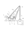
- the perspective view of a pipe layer The front view which shows the working state of a pipe layer.
- the schematic diagram which shows the hydraulic circuit with which a pipe layer is provided.
- the figure which shows the opening characteristic of a warm-up control valve The figure which shows the opening characteristic of a winch control valve.
- FIG. 1 shows a pipe layer 1 according to an embodiment of the present invention.
- FIG. 1 is a perspective view showing the appearance of the pipe layer 1.
- the pipe layer 1 includes a vehicle body 2, a counterweight 3, a boom 4, a hook 5, and a winch device 6.
- the wire 101 for the hook 5 and the wire 102 for the boom 4 described later are omitted for easy understanding of the drawing.
- the vehicle body 2 has an engine room 11, a driver's cab 12, a pair of travel devices 13, 14 and the like.
- the engine room 11 is provided with an engine to be described later.
- the cab 12 and devices such as a hydraulic pump (see FIG. 3) are arranged behind the engine room 11.
- the traveling devices 13 and 14 have covering bands 13a and 14a, respectively.
- the pipe layer 1 travels by driving the covering bands 13a and 14a by the driving force from the engine.
- FIG. 2 is a front view showing a state in which the pipe layer 1 is performing the installation work of the pipe 100.
- the counterweight 3 is attached to the vehicle main body 2 via the arm member 15.
- the counterweight 3 is provided so as to be movable by a hydraulic cylinder 16.
- the pipe layer 1 can balance the vehicle body by adjusting the distance between the counterweight 3 and the vehicle body 2.
- the boom 4 is attached to the other side of the vehicle body 2. That is, the boom 4 is attached to the side portion of the vehicle main body 2 opposite to the counterweight 3. The lower part of the boom 4 is attached to the vehicle body 2 so as to be swingable.
- a first pulley 18 is attached to the upper part of the boom 4.
- the first pulley 18 supports the wire 101 connected to the hook 5.
- a second pulley 17 is disposed on the upper surface of the side of the vehicle body 2 on the boom 4 side.
- the wire 101 connected to the hook 5 passes through the first pulley 18 and the second pulley 17 and extends to a winch for the hook 5 (not shown).
- a boom 4 wire 102 extending from a boom 4 winch, which will be described later, is connected to the upper portion of the boom 4.
- FIG. 3 is a schematic diagram showing a hydraulic drive system for driving the boom 4. As shown in FIG. 3, the pipe layer 1 has a winch 21 for the boom 4.
- the winch 21 is provided in the winch device 6 described above.
- a wire 102 is wound around the winch 21.
- the boom 4 can be swung up and down by the wire 102 being wound up or down by the winch 21.
- the hook 5 shown in FIGS. 1 and 2 moves up and down when the wire 101 is wound up or down by a winch for the hook 5 (not shown).
- the pipe layer 1 includes an engine 22, a first hydraulic pump 23, a hydraulic motor 24, a winch control valve 25, and a warm-up control valve 20.
- the engine 22 is, for example, a diesel engine, and the output of the engine 22 is controlled by adjusting the fuel injection amount from a fuel injection pump (not shown).
- the adjustment of the fuel injection amount is performed by being controlled by a mechanical governor provided in the fuel injection pump.
- a mechanical governor an all-speed control type governor is generally used, and the engine speed and the fuel injection amount are adjusted according to the load by the action of centrifugal force. That is, the governor increases or decreases the fuel injection amount by the displacement of the pair of centrifugal weights attached to the rotating shaft connected to the output shaft of the engine 22.
- the first hydraulic pump 23 is driven by the engine 22 and discharges hydraulic oil.
- a first pump hydraulic circuit 26 is connected to the first hydraulic pump 23.
- the first pump hydraulic circuit 26 is a hydraulic circuit through which the hydraulic oil discharged from the first hydraulic pump 23 passes.
- the first hydraulic pump 23 is a variable displacement hydraulic pump.
- the capacity of the first hydraulic pump 23 is controlled by a pump capacity adjusting unit 27.
- the hydraulic motor 24 is driven by hydraulic oil from the first hydraulic pump 23.
- the hydraulic motor 24 drives the winch 21.
- a drive hydraulic circuit 28 is connected to the hydraulic motor 24.
- the drive hydraulic circuit 28 is a hydraulic circuit through which hydraulic oil for driving the hydraulic motor 24 passes.
- the drive hydraulic circuit 28 includes a first drive hydraulic circuit 29 and a second drive hydraulic circuit 30.
- the first drive hydraulic circuit 29 is connected to the first motor port 24 a of the hydraulic motor 24.
- the second drive hydraulic circuit 30 is connected to the second motor port 24 b of the hydraulic motor 24.
- the hydraulic motor 24 When hydraulic oil is supplied to the first motor port 24a and discharged from the second motor port 24b, the hydraulic motor 24 is driven in one direction (for example, the direction in which the winch 21 is wound up). When hydraulic oil is supplied to the second motor port 24b and discharged from the first motor port 24a, the hydraulic motor 24 is driven in the other direction (for example, the direction in which the winch 21 is wound).
- the winch control valve 25 is provided between the first pump hydraulic circuit 26 and the drive hydraulic circuit 28.
- the winch control valve 25 is connected to a drive drain circuit 31.
- the winch control valve 25 is a pressure proportional control valve, and adjusts the flow rate of hydraulic oil sent from the first pump hydraulic circuit 26 to the drive hydraulic circuit 28 in accordance with the pilot pressure input to the pilot ports pp1 and pp2.
- the winch control valve 25 is switched to states z1, z2, and z3 according to the pilot pressure input to the pilot ports pp1 and pp2.
- the winch control valve 25 when the hydraulic oil is supplied to the pilot port pp1, the winch control valve 25 is in the state z1. When the hydraulic oil is supplied to the pilot port pp2, the winch control valve 25 is in the state z2. As the hydraulic oil is drained from the pilot ports pp1 and pp2, the winch control valve 25 is in the state z3.
- the winch control valve 25 is in the state z1 and communicates the first pump hydraulic circuit 26 and the first drive hydraulic circuit 29 and communicates the second drive hydraulic circuit 30 and the drive drain circuit 31.
- the winch control valve 25 communicates the first pump hydraulic circuit 26 and the second drive hydraulic circuit 30 with the first drive hydraulic circuit 29 and the drive drain circuit 31 in the state z2. Further, the winch control valve 25 is in the state z3, and disconnects the first drive hydraulic circuit 29 and the second drive hydraulic circuit 30 from the first pump hydraulic circuit 26.
- the warm-up control valve 20 is provided between the first pump hydraulic circuit 26 and the warm-up hydraulic circuit 32.
- the warm-up hydraulic circuit 32 is a hydraulic circuit through which hydraulic oil for warming up the hydraulic motor 24 passes.
- the warm-up hydraulic circuit 32 is provided with a throttle 33 as a pressure loss part.
- the hydraulic oil flowing through the warm-up hydraulic circuit 32 generates heat when passing through the throttle 33.
- the warm-up hydraulic circuit 32 passes through the hydraulic motor 24 and is connected to the tank circuit 34.
- the tank circuit 34 is connected to a hydraulic oil tank (not shown).
- the warm-up control valve 20 is a hydraulic directional control valve, and is switched between an open state w1 and a closed state w2 according to the pilot pressure input to the pilot port pp3. Specifically, the warm-up control valve 20 is in the open state w1 by supplying hydraulic oil to the pilot port pp3. When the hydraulic oil is drained from the pilot port pp3, the warm-up control valve 20 is in the closed state w2.
- the warm-up control valve 20 allows the first pump hydraulic circuit 26 and the warm-up hydraulic circuit 32 to communicate with each other in the open state w1 and allows the warm-up drain circuit 35 and the drive drain circuit 31 to communicate with each other.
- the warm-up drain circuit 35 is connected between the throttle 33 and the hydraulic motor 24 in the warm-up hydraulic circuit 32.
- the warm-up control valve 20 shuts off the first pump hydraulic circuit 26 and the warm-up hydraulic circuit 32 and shuts off the warm-up drain circuit 35 and the drive drain circuit 31 in the closed state w2.
- the drive drain circuit 31 is connected to the tank circuit 34 via the back pressure valve 36.
- the back pressure valve 36 is a hydraulic control valve, and is switched between a state x1 and a state x2 according to the pilot pressure input to the pilot port pp4. Specifically, the hydraulic oil is supplied to the pilot port pp4, so that the back pressure valve 36 is in the state x1. When the hydraulic oil is drained from the pilot port pp4, the back pressure valve 36 is in the state x2.
- the back pressure valve 36 connects the drive drain circuit 31 and the tank circuit 34 via the throttle 37 in the state x1.
- the back pressure valve 36 connects the drive drain circuit 31 and the tank circuit 34 without passing through the throttle 37 in the state x2.
- the pipe layer 1 includes a second hydraulic pump 38, a winch operation member 39, a drive pilot pressure control unit 40, and a warm-up pilot pressure control unit 41.
- the second hydraulic pump 38 is driven by the engine 22 and discharges hydraulic oil.
- a second pump hydraulic circuit 42 is connected to the second hydraulic pump 38.
- the second pump hydraulic circuit 42 is a hydraulic circuit through which the hydraulic oil discharged from the second hydraulic pump 38 passes.
- the second hydraulic pump 38 is a fixed displacement hydraulic pump.
- the winch operation member 39 is disposed in the cab 12 and is a member for the operator to operate the winch 21.
- the winch operation member 39 is, for example, a lever member.
- the winch operation member 39 can be operated in a winding position, a lowering position, and a neutral position.
- the drive pilot pressure control unit 40 adjusts the pilot pressure input to the pilot ports pp1 and pp2 of the winch control valve 25 in accordance with the operation of the winch operation member 39.
- the drive pilot pressure control unit 40 is disposed between the second pump hydraulic circuit 42 and the pilot hydraulic circuits pc1 and pc2.
- the pilot hydraulic circuit pc1 is connected to the pilot port pp1 of the winch control valve 25.
- the pilot hydraulic circuit pc2 is connected to the pilot port pp2 of the winch control valve 25.
- the drive pilot pressure control unit 40 supplies hydraulic oil to the pilot port pp1 of the winch control valve 25 via the pilot hydraulic circuit pc1.
- the drive pilot pressure control unit 40 supplies hydraulic oil to the pilot port pp2 of the winch control valve 25 via the pilot hydraulic circuit pc2.
- the winch control valve 25 is set to the state z1 or the state z2, and the hydraulic oil 24 is supplied to the hydraulic motor 24, whereby the winch 21 is driven.
- the drive pilot pressure control unit 40 supplies hydraulic oil to the pilot port pp4 of the back pressure valve 36.
- back pressure is generated in the drive drain circuit 31 during the operation of the winch 21.
- the drive pilot pressure control unit 40 drains hydraulic oil from the pilot port pp4 of the back pressure valve 36.
- the warm-up pilot pressure control unit 41 adjusts the pilot pressure input to the pilot port pp3 of the warm-up control valve 20 according to the operation of the winch operation member 39.
- the warm-up pilot pressure control unit 41 is disposed between the pilot hydraulic circuits pc1 and pc2 and the pilot hydraulic circuit pc3.
- the pilot hydraulic circuit pc3 is connected to the pilot port pp3 of the warm-up control valve 20.
- the warm-up pilot pressure control unit 41 drains hydraulic oil from the pilot port pp3 of the warm-up control valve 20. Thereby, the warm-up control valve 20 is set to the closed state w2. For this reason, hydraulic oil is not supplied to the warm-up hydraulic circuit 32 and warm-up is not performed. That is, the warm-up pilot pressure control unit 41 operates from the pilot port pp3 of the warm-up control valve 20 so that the warm-up control valve 20 is in the closed state w2 when the winch control valve 25 is in the open state z1 or z2. Drain the oil. This prevents warming up during the operation of the winch 21.
- the warm-up pilot pressure control unit 41 supplies hydraulic oil to the pilot port pp3 of the warm-up control valve 20 through the pilot circuit pc3. Therefore, when the winch control valve 25 is in the closed state z3, the warm-up pilot pressure control unit 41 supplies hydraulic oil to the pilot port of the warm-up control valve 20 so that the warm-up control valve 20 is in the open state w1. To do. Thereby, warm-up is performed while the winch 21 is stopped.
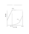
- FIG. 4 shows the opening characteristics of the warm-up control valve 20.
- a solid line L1out indicates the relationship between the stroke amount of the warm-up control valve 20 and the meter-out opening area.
- a broken line L1in indicates the relationship between the stroke amount of the warm-up control valve 20 and the meter-in opening area.
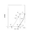
- FIG. 5 shows the opening characteristics of the winch control valve 25.
- the solid line L2in indicates the relationship between the stroke amount of the winch control valve 25 and the meter-in opening area.
- a broken line L2out indicates the relationship between the stroke amount of the warm-up control valve 20 and the meter-out opening area.
- stroke amount means the stroke amount from the stroke end on the closed side of the spool of each control valve. That is, a stroke amount of “0” means that the spool is positioned at the stroke end on the closing side.
- the maximum stroke amount Smax1 of the warm-up control valve 20 shown in FIG. 4 is substantially the same as the maximum stroke amount Smax2 of the winch control valve 25 shown in FIG.
- the scales of the vertical axes in FIGS. 4 and 5 do not necessarily match, and the positions of the vertical axes in FIGS. 4 and 5 indicate the opening area of the warm-up control valve 20 and the opening area of the winch control valve 25. It does not necessarily indicate the size relationship.
- the stroke amount of the warm-up control valve 20 when the meter-out opening of the warm-up control valve 20 is fully closed that is, “0” is S1.
- the warm-up control valve 20 has an opening characteristic in which the meter-out opening area increases as the stroke amount increases from S1 to Smax1.
- the stroke amount of the warm-up control valve 20 reaches Smax1, the area of the meter-out opening of the warm-up control valve 20 is maximized. That is, when the stroke position of the warm-up control valve 20 reaches the stroke end on the open side, the area of the meter-out opening of the warm-up control valve 20 is maximized.
- the meter-out opening characteristic of the warm-up control valve 20 has an inflection point Pinf.
- the meter-out opening characteristic of the warm-up control valve 20 has a bent shape so that the change rate of the opening area increases on the opening side from the inflection point Pinf.
- the warm-up control valve 20 has an opening characteristic in which the meter-in opening area increases as the stroke amount increases from S1 to Smax1. However, the area of the meter-in opening of the warm-up control valve 20 is maximized at S1 'where the stroke amount is smaller than Smax1. S1 'is larger than S1.
- the stroke amount of the winch control valve 25 when the meter-in opening of the winch control valve 25 is fully closed that is, “0” is S2.
- the winch control valve 25 has an opening characteristic in which the meter-in opening area increases as the stroke amount increases from S2 to Smax2.
- Smax2 the area of the meter-in opening of the winch control valve 25 is maximized. That is, when the stroke position of the winch control valve 25 reaches the stroke end on the open side, the area of the meter-in opening of the winch control valve 25 is maximized.
- the warm-up control valve 20 has an opening characteristic in which the meter-out opening area increases as the stroke amount increases from 0 to Smax2. However, the area of the meter-out opening of the warm-up control valve 20 is maximized at S2 'where the stroke amount is smaller than Smax2. S2 'is larger than S1.
- the stroke amount S1 of the warm-up control valve 20 when the meter-out opening of the warm-up control valve 20 is fully closed corresponds to the stroke amount S1 when the meter-in opening of the winch control valve 25 is fully closed.
- the stroke amount S2 of the winch control valve 25 is larger.
- the stroke amount S1 of the warm-up control valve 20 when the meter-out opening of the warm-up control valve 20 is fully closed is based on the stroke amount S2 of the winch control valve 25 when the meter-in opening of the winch control valve 25 is fully closed. Is also big. In other words, the stroke amount (Smax1-S1) until the meter-out opening of the warm-up control valve 20 is fully opened to fully closed is equal to the stroke amount (Smax2-S2) until the meter-in opening of the winch control valve 25 is fully opened to fully closed. Smaller than).
- a broken line L1out ' indicates the meter-out opening characteristic of the warm-up control valve according to the virtual comparative example.
- the meter-out opening characteristic of the warm-up control valve according to the comparative example is set similarly to the meter-in opening characteristic of the winch control valve 25. That is, as indicated by the broken line L1out ′, in the meter-out opening characteristic of the warm-up control valve according to the comparative example, the meter-out opening is fully closed, that is, “0”, similarly to the meter-in opening characteristic L2in of the winch control valve 25.
- the stroke amount at that time is S2.
- the change in the opening area when the warm-up control valve 20 is switched from the open state w1 to the closed state w2 will be described as follows.
- the spool is located at the stroke end on the closing side, that is, the stroke amount is Smax1.
- the opening area is fully open (see point P1).
- the stroke amount decreases from Smax1.
- the opening area decreases immediately when the stroke amount decreases from Smax1.
- the opening area does not immediately decrease even when the stroke amount decreases from Smax1, but the opening area does not decrease until the stroke amount reaches Sa. Remains at the maximum (see point P2 ′).
- the opening area starts to decrease.
- the opening area is already less than half of the maximum value (see point P2).
- the opening area becomes 0 (see point P3). That is, the warm-up control valve 20 is in the closed state w2.
- the opening area is still larger than half of the maximum value (see point P3 ').
- the opening area becomes 0, and the warm-up control valve 20 enters the closed state w2 (see point P4 ').
- the meter-out opening is switched from fully open to fully closed with a smaller stroke amount than the warm-up control valve according to the comparative example. For this reason, even if the hydraulic oil drained from the pilot port of the warm-up control valve 20 is at a low temperature, the warm-up control valve 20 can be quickly switched from the open state w1 to the closed state w2. For this reason, the time when both the warm-up control valve 20 and the winch control valve 25 are in the open state can be reduced or avoided. Thereby, it is possible to stably avoid simultaneous operation of driving of the winch 21 and warm-up operation even in an extremely cold environment.
- the meter-out opening characteristic of the warm-up control valve 20 has an inflection point Pinf.
- the meter-out opening can be switched from fully open to fully closed with a short stroke amount.
- the hydraulic circuit of the hydraulic drive system is not limited to that described above, and an equivalent hydraulic circuit may be used.
- the form of the operation member described above is not limited to a lever or switch, and other forms may be employed.
- the warm-up of the hydraulic motor 24 and the warm-up of the hydraulic motor 24 are performed at the same time, but may be performed separately.
- the throttle 33 is used as a pressure loss part for heat generation, but a relief valve set to a predetermined relief pressure may be used.
- the hydraulic drive system for driving and warming up the hydraulic motor 24 for the boom 4 is described.
- the hydraulic drive system for driving and warming up the hydraulic motor 24 for the hook 5 is used.
- the present invention may be applied.
- the hydraulic drive system for driving and warming up the hydraulic motor 24 for the hook 5 has the same configuration as the hydraulic drive system for driving and warming up the hydraulic motor 24 for the boom 4 described above.
Landscapes
- Engineering & Computer Science (AREA)
- Mechanical Engineering (AREA)
- General Engineering & Computer Science (AREA)
- Chemical & Material Sciences (AREA)
- Analytical Chemistry (AREA)
- Physics & Mathematics (AREA)
- Fluid Mechanics (AREA)
- Life Sciences & Earth Sciences (AREA)
- Agronomy & Crop Science (AREA)
- Fluid-Pressure Circuits (AREA)
- Operation Control Of Excavators (AREA)
Abstract
Description
21 ウインチ
22 エンジン
23 第1油圧ポンプ
24 油圧モータ
25 ウインチ制御弁
40 駆動パイロット圧制御部
26 暖機制御弁
26 第1ポンプ油圧回路
28 駆動油圧回路
32 暖機油圧回路
41 暖機パイロット圧制御部
Claims (4)
- エンジンと、
前記エンジンによって駆動される油圧ポンプと、
前記油圧ポンプから吐出された作動油によって駆動される油圧モータと、
前記油圧モータによって駆動されるウインチと、
前記油圧ポンプから吐出された作動油が通るポンプ油圧回路と、
前記油圧モータに接続され、前記油圧モータを駆動するための作動油が通る駆動油圧回路と、
前記油圧モータに接続され、前記油圧モータを暖機するための作動油が通る暖機油圧回路と、
前記ポンプ油圧回路と前記駆動油圧回路との間に設けられ、開状態で前記ポンプ油圧回路と前記駆動油圧回路とを連通させ、閉状態で前記ポンプ油圧回路と前記駆動油圧回路とを遮断するウインチ制御弁と、
前記ポンプ油圧回路と前記暖機油圧回路との間に設けられ、開状態で前記ポンプ油圧回路と前記暖機油圧回路とを連通させ、閉状態で前記ポンプ油圧回路と前記暖機油圧回路とを遮断する暖機制御弁と、
前記ウインチ制御弁が閉状態であるときには、前記暖機制御弁が開状態となるように、前記暖機制御弁のパイロットポートに作動油を供給し、前記ウインチ制御弁が開状態であるときには、前記暖機制御弁が閉状態となるように、前記暖機制御弁のパイロットポートから作動油をドレンするパイロット圧制御部と、
を備え、
前記暖機制御弁のメータアウト開口が全閉となるときの前記暖機制御弁のスプールの閉じ側のストロークエンドからのストローク量は、前記ウインチ制御弁のメータイン開口が全閉となるときの前記ウインチ制御弁のスプールの閉じ側のストロークエンドからのストローク量よりも大きい、
パイプレイヤ。 - 前記ウインチ制御弁のメータイン開口が全閉となるときの前記ウインチ制御弁のスプールのストローク位置は、前記ウインチ制御弁の開き側のストロークエンドよりも前記閉じ側のストロークエンドに近く、
前記暖機制御弁のメータアウト開口が全閉となるときの前記暖機制御弁のスプールのストローク位置は、前記暖機制御弁の閉じ側のストロークエンドよりも開き側のストロークエンドに近い、
請求項1に記載のパイプレイヤ。 - 前記暖機制御弁のスプールのストローク位置が開き側のストロークエンドに達したときに、前記暖機制御弁のメータアウト開口の面積は最大となる、
請求項1又は2に記載のパイプレイヤ。 - 前記暖機制御弁のスプールのストローク量に対するメータアウト開口の面積を示す前記暖機制御弁のメータアウト開口特性は、変曲点を有する、
請求項1から3のいずれかに記載のパイプレイヤ。
Priority Applications (4)
| Application Number | Priority Date | Filing Date | Title |
|---|---|---|---|
| JP2013539042A JP5442914B1 (ja) | 2013-05-20 | 2013-05-20 | パイプレイヤ |
| US14/114,963 US9021796B2 (en) | 2013-05-20 | 2013-05-20 | Pipelayer |
| CN201380001622.XA CN103748030B (zh) | 2013-05-20 | 2013-05-20 | 管道敷设机 |
| PCT/JP2013/063957 WO2014188491A1 (ja) | 2013-05-20 | 2013-05-20 | パイプレイヤ |
Applications Claiming Priority (1)
| Application Number | Priority Date | Filing Date | Title |
|---|---|---|---|
| PCT/JP2013/063957 WO2014188491A1 (ja) | 2013-05-20 | 2013-05-20 | パイプレイヤ |
Publications (1)
| Publication Number | Publication Date |
|---|---|
| WO2014188491A1 true WO2014188491A1 (ja) | 2014-11-27 |
Family
ID=50504639
Family Applications (1)
| Application Number | Title | Priority Date | Filing Date |
|---|---|---|---|
| PCT/JP2013/063957 Ceased WO2014188491A1 (ja) | 2013-05-20 | 2013-05-20 | パイプレイヤ |
Country Status (4)
| Country | Link |
|---|---|
| US (1) | US9021796B2 (ja) |
| JP (1) | JP5442914B1 (ja) |
| CN (1) | CN103748030B (ja) |
| WO (1) | WO2014188491A1 (ja) |
Families Citing this family (4)
| Publication number | Priority date | Publication date | Assignee | Title |
|---|---|---|---|---|
| US20150033720A1 (en) * | 2013-08-05 | 2015-02-05 | Caterpillar Inc. | Hydraulic Motor Drive System and Method |
| US9850637B2 (en) | 2014-03-24 | 2017-12-26 | Soilmec S.P.A. | Digging equipment with relative improved hydraulic system |
| US10451094B2 (en) * | 2015-09-28 | 2019-10-22 | Kubota Corporation | Hydraulic system of work machine |
| JP7033966B2 (ja) * | 2018-03-16 | 2022-03-11 | 住友重機械建機クレーン株式会社 | 油圧ウインチの制御装置 |
Citations (5)
| Publication number | Priority date | Publication date | Assignee | Title |
|---|---|---|---|---|
| JPH10274212A (ja) * | 1997-03-28 | 1998-10-13 | Shin Caterpillar Mitsubishi Ltd | 流体回路における暖機方法およびその装置 |
| JPH11108015A (ja) * | 1997-10-06 | 1999-04-20 | Komatsu Ltd | 建設機械の油圧駆動装置 |
| JP2000074011A (ja) * | 1997-09-04 | 2000-03-07 | Yutani Heavy Ind Ltd | 油圧作業機械の暖機運転装置 |
| JP2003239907A (ja) * | 2002-02-19 | 2003-08-27 | Kubota Corp | 作業機の油圧装置 |
| WO2012086695A1 (ja) * | 2010-12-21 | 2012-06-28 | 株式会社小松製作所 | パイプレイヤ及びパイプレイヤの暖機方法 |
Family Cites Families (10)
| Publication number | Priority date | Publication date | Assignee | Title |
|---|---|---|---|---|
| GB1335386A (en) * | 1970-06-26 | 1973-10-24 | Caterpillar Tractor Co | Systems for operating and controlling hydraulically driven winches hoists and the like |
| US3972185A (en) * | 1975-02-28 | 1976-08-03 | Caterpillar Tractor Co. | Hydraulic system for a pipelayer |
| US3969897A (en) * | 1975-02-28 | 1976-07-20 | Caterpillar Tractor Co. | Temperature-control arrangement for a pair of hydraulic motors |
| US4048799A (en) * | 1976-11-17 | 1977-09-20 | Caterpillar Tractor Co. | Winch control |
| US4354351A (en) * | 1980-09-29 | 1982-10-19 | Caterpillar Tractor Co. | Load sensing steering |
| US4972762A (en) * | 1989-03-06 | 1990-11-27 | Kubik Philip A | Warm-up circuit for hydraulic pilot control system |
| FR2714663B1 (fr) * | 1993-12-30 | 1996-01-26 | Thomson Csf | Treuil à moteur hydraulique, notamment pour hélicoptère muni d'un sonar. |
| DE602006019343D1 (de) * | 2005-03-31 | 2011-02-17 | Nabtesco Corp | Steuervorrichtung des Antriebsmotors einer Arbeitsmaschine |
| KR100974283B1 (ko) * | 2008-08-08 | 2010-08-06 | 볼보 컨스트럭션 이키프먼트 홀딩 스웨덴 에이비 | 굴삭 및 파이프 레잉 작업을 위한 유량 분배 시스템 |
| US8234860B2 (en) * | 2008-08-29 | 2012-08-07 | Caterpillar Inc. | Machine control system having hydraulic warmup procedure |
-
2013
- 2013-05-20 CN CN201380001622.XA patent/CN103748030B/zh not_active Expired - Fee Related
- 2013-05-20 JP JP2013539042A patent/JP5442914B1/ja not_active Expired - Fee Related
- 2013-05-20 WO PCT/JP2013/063957 patent/WO2014188491A1/ja not_active Ceased
- 2013-05-20 US US14/114,963 patent/US9021796B2/en active Active
Patent Citations (5)
| Publication number | Priority date | Publication date | Assignee | Title |
|---|---|---|---|---|
| JPH10274212A (ja) * | 1997-03-28 | 1998-10-13 | Shin Caterpillar Mitsubishi Ltd | 流体回路における暖機方法およびその装置 |
| JP2000074011A (ja) * | 1997-09-04 | 2000-03-07 | Yutani Heavy Ind Ltd | 油圧作業機械の暖機運転装置 |
| JPH11108015A (ja) * | 1997-10-06 | 1999-04-20 | Komatsu Ltd | 建設機械の油圧駆動装置 |
| JP2003239907A (ja) * | 2002-02-19 | 2003-08-27 | Kubota Corp | 作業機の油圧装置 |
| WO2012086695A1 (ja) * | 2010-12-21 | 2012-06-28 | 株式会社小松製作所 | パイプレイヤ及びパイプレイヤの暖機方法 |
Also Published As
| Publication number | Publication date |
|---|---|
| JP5442914B1 (ja) | 2014-03-19 |
| US20140338317A1 (en) | 2014-11-20 |
| US9021796B2 (en) | 2015-05-05 |
| CN103748030A (zh) | 2014-04-23 |
| JPWO2014188491A1 (ja) | 2017-02-23 |
| CN103748030B (zh) | 2015-06-03 |
Similar Documents
| Publication | Publication Date | Title |
|---|---|---|
| US9187297B2 (en) | Hydraulic driving apparatus for working machine | |
| JP5205552B2 (ja) | パイプレイヤ及びパイプレイヤの暖機方法 | |
| CS238619B2 (en) | Hydrostatic driving system with adjustable pump and a number of consumers | |
| JP5442914B1 (ja) | パイプレイヤ | |
| JP6776334B2 (ja) | ショベル及びショベル用コントロールバルブ | |
| JP7026657B2 (ja) | 建設機械の油圧回路 | |
| JP2010156136A (ja) | 建設機械の旋回ブレーキ装置 | |
| WO2016181635A1 (ja) | 建設機械の油圧駆動システム | |
| CN107407299A (zh) | 建筑机械的油压驱动系统 | |
| JP5097051B2 (ja) | 建設機械の油圧制御装置 | |
| CN101634373A (zh) | 具有摆动速度可调系统的铺管机 | |
| EP2989350B1 (en) | Hydraulic circuit for the transmissions of industrial and agricultural vehicles | |
| JP2000310201A (ja) | 油圧作業機械のアクチュエータ制御回路 | |
| JP6924161B2 (ja) | 建設機械の油圧システム | |
| WO2016092809A1 (ja) | 建設機械の油圧駆動システム | |
| JP6306944B2 (ja) | 油圧作業車両 | |
| JP2016017602A (ja) | 作業機械の駆動装置 | |
| RU2679942C1 (ru) | Гидравлический контроллер для гидравлически управляемого поднимаемого и опускаемого крюка крана | |
| KR102385608B1 (ko) | 쇼벨 및 쇼벨용 컨트롤밸브 | |
| JP2011153572A (ja) | 建設機械のポンプ制御装置 | |
| US9096414B2 (en) | Crane control system | |
| CN103775409B (zh) | 静液压驱动系统 | |
| JPH08120709A (ja) | 油圧作業機の油圧回路 | |
| JP3766827B2 (ja) | 油圧駆動装置 | |
| JPH0637091Y2 (ja) | 土木・建設機械の油圧駆動装置 |
Legal Events
| Date | Code | Title | Description |
|---|---|---|---|
| ENP | Entry into the national phase |
Ref document number: 2013539042 Country of ref document: JP Kind code of ref document: A |
|
| WWE | Wipo information: entry into national phase |
Ref document number: 14114963 Country of ref document: US |
|
| 121 | Ep: the epo has been informed by wipo that ep was designated in this application |
Ref document number: 13885088 Country of ref document: EP Kind code of ref document: A1 |
|
| NENP | Non-entry into the national phase |
Ref country code: DE |
|
| 122 | Ep: pct application non-entry in european phase |
Ref document number: 13885088 Country of ref document: EP Kind code of ref document: A1 |