WO2014185396A1 - 溶接装置、および、溶接装置の通信方法 - Google Patents
溶接装置、および、溶接装置の通信方法 Download PDFInfo
- Publication number
- WO2014185396A1 WO2014185396A1 PCT/JP2014/062683 JP2014062683W WO2014185396A1 WO 2014185396 A1 WO2014185396 A1 WO 2014185396A1 JP 2014062683 W JP2014062683 W JP 2014062683W WO 2014185396 A1 WO2014185396 A1 WO 2014185396A1
- Authority
- WO
- WIPO (PCT)
- Prior art keywords
- welding
- signal
- communication
- power source
- unit
- Prior art date
- Legal status (The legal status is an assumption and is not a legal conclusion. Google has not performed a legal analysis and makes no representation as to the accuracy of the status listed.)
- Ceased
Links
Images




Classifications
-
- B—PERFORMING OPERATIONS; TRANSPORTING
- B23—MACHINE TOOLS; METAL-WORKING NOT OTHERWISE PROVIDED FOR
- B23K—SOLDERING OR UNSOLDERING; WELDING; CLADDING OR PLATING BY SOLDERING OR WELDING; CUTTING BY APPLYING HEAT LOCALLY, e.g. FLAME CUTTING; WORKING BY LASER BEAM
- B23K9/00—Arc welding or cutting
- B23K9/10—Other electric circuits therefor; Protective circuits; Remote controls
- B23K9/1087—Arc welding using remote control
-
- H—ELECTRICITY
- H04—ELECTRIC COMMUNICATION TECHNIQUE
- H04B—TRANSMISSION
- H04B3/00—Line transmission systems
- H04B3/54—Systems for transmission via power distribution lines
Definitions
- the present invention relates to a welding apparatus that operates a welding power supply device with a remote control device. Moreover, this invention relates to the communication method of such a welding apparatus.
- the consumable electrode type welding device includes a welding power source device for supplying electric power necessary for welding, a wire feeding device, and the like. Since the welding power source device is heavy, it is used by being installed at a predetermined location. On the other hand, the wire feeder is carried by a welding operator in accordance with the change of the welding location. When the welding power source is located away from the position where the welding operation is performed, in order to set the welding conditions (for example, the welding voltage value), the operator must move to the installation location of the welding power source. , Work efficiency worsens. In order to improve this problem, there has been proposed a technique for changing welding conditions using a remote control device that performs wireless communication with a welding power source device (see Patent Document 1).
- the welding power source and the welding location may be several tens of meters apart. In such a welding site, it is very convenient if the welding conditions can be set with respect to the welding power source device by a wireless remote control device. However, if a partition wall or the like exists between the remote control device and the welding power source device, a failure may occur in wireless communication.
- a plurality of welding apparatuses may be used in welding sites of large structures.
- a radio signal for one welding apparatus may cause problems such as interference of radio signals for other welding apparatuses or mixing of noise.
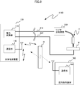
- FIG. 1 shows a state in which wireless communication is performed between the remote control device 300 of the conventional welding device A100 and the welding power source device 100.
- the welding power supply device 100 is disposed at a position away from the workpiece W, and the wire feeding device 200 is disposed near the workpiece W.
- the welding operator has a remote operation device 300 for remotely operating the welding power source device 100.
- a signal output from the communication unit 360 of the remote control device 300 is sent to the communication unit 140 of the welding power source device 100. It may not be received correctly.
- remote control device 300 and welding power supply device 100 are separated from each other, a transmission signal of another welding device in between may be received, or noise generated from other devices may be mixed.
- the welding conditions set by the remote operation device 300 are not accurately communicated to the welding power source device 100, so that welding becomes unstable and the welding quality deteriorates.
- an object of the present invention is to provide a welding apparatus capable of accurately performing communication between a remote control device using wireless communication and a welding power source device.
- the present invention takes the following technical means.
- a welding device provided by the first aspect of the present invention includes a welding power source device, a power transmission line connected to the welding power source device, a relay device provided on the power transmission line, and the relay device. And a remote control device that performs wireless communication between them.
- the welding power supply device and the relay device are configured to perform communication via the power transmission line.
- the welding power supply device is configured to perform wireless communication with the remote control device.
- the welding power source device includes a comparison unit that directly compares a direct signal received from the remote control device by wireless communication with an indirect signal received through the relay device and the power transmission line, and the comparison unit. Processing means for performing a predetermined process when it is determined that the direct signal and the indirect signal are the same.
- Retransmission request means for requesting the operation device to retransmit the signal is provided.
- the welding power source apparatus includes a counting unit that counts the number of times the comparison unit performs comparison.
- the processing means is configured to perform processing based on a signal received via the relay device and the power transmission line when the number counted by the counting means exceeds a predetermined number.
- the relay device when the processing means determines that the direct signal and the indirect signal are different by the comparison means, the relay device And it is comprised so that a process may be performed based on the signal received via the said power transmission line.
- the welding power supply apparatus includes first communication means for receiving a welding condition setting signal for setting a welding condition;
- the first storage control means for changing the welding condition parameter stored in the first storage means based on the welding condition setting signal received by the first communication means, and the first storage control means stored in the first storage means.
- Output control means for controlling the output of the welding power source device based on the welding condition parameters.
- the first communication means is configured to transmit the welding condition parameter stored in the first storage means as a welding condition parameter signal.
- the remote control device is configured to change a welding condition stored in the second storage unit based on an operation by a welding operator, and the welding stored in the second storage unit.
- Display means for performing display based on the condition, and second communication for transmitting the welding condition stored in the second storage means as a welding condition signal and receiving the welding condition parameter signal transmitted by the first communication means.
- Means, third storage means for storing welding condition parameters based on the welding condition parameter signal received by the second communication means, the welding conditions stored in the second storage means, and the third storage means The welding condition parameters stored in the table are compared to determine whether or not they match, and a report for performing predetermined notification based on the determination result by the determination unit. It is provided with a means, a.
- the relay device is a wire feeding device.
- the relay device is a welding torch.
- a relay device used for a welding apparatus is provided.
- This relay device is provided on a power transmission line through which the welding power supply device supplies power.
- the relay device is configured to perform wireless communication with a remote control device for remotely controlling the welding power source device, and via the power transmission line with the welding power source device. It is configured to communicate.
- a welding power supply device a power transmission line for supplying power by the welding power supply device, a relay device provided on the power transmission line, and the welding power supply device.
- a communication method for a welding apparatus including a remote control device for remote control. The communication method includes: a first step in which the remote operation device transmits a signal by radio; a second step in which the relay device receives a signal transmitted by the remote operation device; and the relay device, A third step of transmitting the received signal to the welding power source device via the power transmission line; and a fourth step of the welding power source device receiving a signal transmitted via the power transmission line; It is equipped with.
- the remote control device and the wire feeding device perform wireless communication, and the wire feeding device and the welding power supply device perform wired communication via the power transmission line. Since the remote control device is located near the wire feeding device, there is little possibility that a partition wall or other welding device exists between them, and it is difficult for a failure to occur in wireless communication. Further, since the wire feeding device and the welding power source device are wired communication, even if they are separated from each other, it is difficult for communication to occur. Therefore, compared with the conventional case where the remote control device performs direct wireless communication with the welding power source device, it is less likely to cause a failure in communication, and communication can be performed more accurately.
- FIG. 1 is a diagram for explaining the overall configuration of the welding apparatus according to the first embodiment.
- the welding apparatus A includes a welding power source apparatus 1, a wire feeding apparatus 2, a remote control apparatus 3, two power cables 41 and 42, and a welding torch T.
- the welding power source device 1 includes two output terminals, and one output terminal is connected to the wire feeding device 2 via a power cable 41.
- the wire feeding device 2 feeds the wire electrode to the welding torch T and causes the tip of the wire electrode to protrude from the tip of the welding torch T.
- the power cable 41 and the wire electrode are electrically connected.
- the other output terminal of the welding power source apparatus 1 is connected to the workpiece W via the power cable 42.
- the welding power source apparatus 1 generates an arc by applying a high voltage between the tip of the wire electrode protruding from the tip of the welding torch T and the workpiece W, and welds the workpiece W by the heat of the arc. Is done.
- the welding apparatus A may include a shield gas gas tank for discharging from the welding torch T, a cooling water circulation device for circulating cooling water for cooling the welding torch T, and the like as necessary.
- the welding power supply device 1 supplies power for generating an arc.
- the welding power supply device 1 includes a power conversion unit 11, a storage unit 12, a control unit 13, and a communication unit 14.
- the power converter 11 converts three-phase AC power input from an external power system into DC power suitable for arc welding and outputs the DC power.
- the three-phase AC power input to the power conversion unit 11 is converted to DC power by the rectifier circuit, and is converted to AC power by the inverter circuit.
- the voltage is boosted by a transformer, converted into DC power by a rectifier circuit, and output.
- the configuration of the power conversion unit 11 is not limited to the above.
- the storage unit 12 stores a welding condition parameter Wp such as a setting voltage for setting a welding voltage output from the welding power supply device 1 and a setting current for setting a welding current output from the welding power supply device 1. Is.
- the control unit 13 controls the welding power source apparatus 1 and is realized by, for example, a microcomputer.
- the control unit 13 performs control so that the welding voltage and welding current output from the welding power source device 1 become the set voltage and set current stored in the storage unit 12. Further, the welding condition parameter Wp stored in the storage unit 12 is changed according to the operation of the setting button (not shown), or the power conversion unit 11 is started up according to the operation of the start button (not shown). Control such as.
- the control unit 13 displays a detection value of the welding voltage and welding current detected by a sensor (not shown) on a display unit (not shown), or notifies a notification unit (not shown) when an abnormality occurs. I will let you.
- control unit 13 also changes the welding condition parameter Wp or starts the power conversion unit 11 based on the signal input from the communication unit 14, and detects the detected welding voltage or welding current detection signal or abnormality. A signal indicating the occurrence is output to the communication unit 14.
- control unit 13 reads out the welding condition parameter Wp stored in the storage unit 12 and outputs the welding condition parameter Wp to the communication unit 14 for each preset transmission cycle.
- the transmission cycle is set in the range of about 10 to 500 ms.
- the communication unit 14 is for performing communication with the wire feeding device 2 via the power cable 41.
- the communication unit 14 demodulates the signal received from the wire feeding device 2 and outputs the demodulated signal to the control unit 13.
- the signal received from the wire feeder 2 includes, for example, a welding condition setting signal for changing the welding condition parameter Wp stored in the storage unit 12, an activation signal for instructing activation of the power conversion unit 11, and the like.
- the communication unit 14 modulates a signal input from the control unit 13 and transmits the modulated signal to the wire feeding device 2.
- the signal transmitted to the wire feeding device 2 includes, for example, a detected welding voltage or welding current detection signal, a signal indicating the occurrence of an abnormality, and a welding condition parameter Wp stored in the storage unit 12. There are welding condition parameter signals.
- the signal transmitted / received between the wire feeding apparatuses 2 is not limited to what was mentioned above.
- the communication unit 14 performs communication using a direct spread spectrum (Direct Spread Spectrum: DSSS) communication method.
- DSSS Direct Spread Spectrum
- the transmission side performs an operation using a spread code on a signal to be transmitted, and spreads the spectrum of the original signal in a wider band and transmits the signal.
- the receiving side restores the original signal by despreading the received signal using a common spreading code. If a different spreading code is used for each welding apparatus, even if a signal transmitted / received by another welding apparatus is received, the signal is despread with a different spreading code and removed as noise. Therefore, communication can be performed with high communication quality.
- the communication unit 14 includes a coil disposed around the power cable 41 and magnetically coupled to the power cable 41.
- the communication unit 14 transmits a signal with the power cable 41 via the coil, and detects a signal transmitted with the power cable 41 with the coil.
- the communication unit 14 performs BPSK (Binary Phase Shift Keying) modulation on the carrier signal according to the signal input from the control unit 13, performs spectrum spread on the modulated signal, converts the signal into an analog signal, and transmits the analog signal.
- BPSK Binary Phase Shift Keying
- the modulation method is not limited to BPSK modulation, and ASK modulation or FSK modulation may be performed.
- the spread spectrum is not limited to the direct spreading method, and a frequency hopping method may be used. In this embodiment, the spectrum spread is performed.
- the communication unit 14 detects a signal transmitted by the power cable 41 with a coil, converts the signal into a digital signal, performs despreading and filtering, performs demodulation, and outputs the signal to the control unit 13. Note that the signal transmitted from the welding power supply apparatus 1 to the wire feeding apparatus 2 and the signal transmitted from the wire feeding apparatus 2 to the welding power supply apparatus 1 use different frequency bands.
- the wire feeding device 2 feeds the wire electrode to the welding torch T.
- the wire feeding device 2 controls the feeding motor (not shown) and feeds the wire electrode.
- the wire feeding device 2 also has a function of relaying communication between the welding power source device 1 and the remote control device 3 and includes a relay unit 21.
- the relay unit 21 relays communication between the welding power source device 1 and the remote control device 3.
- the relay unit 21 performs wired communication with the welding power supply device 1 via the power cable 41 and performs wireless communication with the remote control device 3.
- the relay unit 21 detects the signal transmitted by the welding power supply device 1 with a coil disposed around the power cable 41, amplifies the detected signal, and transmits the detected signal to the remote control device 3 as an electromagnetic wave.
- the relay part 21 receives the electromagnetic wave which the remote control apparatus 3 outputs with an antenna, amplifies the received signal, and transmits with the power cable 41 via a coil. Note that the relay unit 21 may transmit the received signal as it is without amplifying it.
- the signal received by the relay unit 21 may be once demodulated, subjected to predetermined processing, and then modulated and transmitted.
- the wire feeding device 2 is controlled by a signal transmitted from the welding power source device 1, demodulation and modulation at the relay unit 21 are necessary.
- the remote control device 3 is for operating the welding power source device 1 from a remote position.
- the remote control device 3 activates the power conversion unit 11 of the welding power source device 1 or changes the welding condition parameter Wp of the welding power source device 1. Further, the detected value of the welding voltage or welding current detected by the welding power supply device 1 is displayed, or an abnormality occurring in the welding power supply device 1 is notified.
- the remote operation device 3 includes an operation unit 31, a storage unit 32, a display unit 33, a notification unit 34, a control unit 35, and a communication unit 36.
- the operation unit 31 outputs an operation button operation by the welding operator to the control unit 35 as an operation signal.
- FIG. 2 shows an example of the external appearance of the remote control device 3.
- a welding current setting button 31a, a welding voltage setting button 31b, and an activation button 31c are arranged as operation buttons on the operation unit 31 of the remote operation device 3.
- the welding current setting button 31a is for changing the setting current of the welding current output from the welding power source device 1.
- the welding voltage setting button 31b is for changing the setting voltage of the welding voltage output from the welding power source device 1.
- the activation button 31 c is for activating the power conversion unit 11 of the welding power supply device 1.
- the operation unit 31 outputs an operation signal for changing welding conditions to the control unit 35.
- the activation button 31 c When the activation button 31 c is operated, the operation unit 31 outputs an operation signal for activation to the control unit 35.
- Note that other operation buttons may be arranged on the operation unit 31. Details of the operation of each operation button will be described later.
- the storage unit 32 stores the welding condition Wr set by the operation of the operation button of the operation unit 31.
- the storage unit 32 also stores a welding condition parameter Wp received as a welding condition parameter signal from the welding power supply device 1.
- the storage unit 32 stores the welding condition Wr and the welding condition parameter Wp in respective determined storage areas.
- the display unit 33 performs various displays (see FIG. 2), and is realized by, for example, a liquid crystal display device.
- the display unit 33 is controlled by the control unit 35, displays the welding condition Wr stored in the storage unit 32, and also displays the result of determination processing described later. Moreover, the display of the detected value of the welding voltage detected by the welding power supply device 1 or welding current is also performed.
- the notification unit 34 performs predetermined notification and is realized by, for example, a speaker.
- the notification unit 34 is controlled by the control unit 35 and notifies the abnormality of the welding power source device 1 with a warning sound.
- the result of determination processing described later is also notified.
- reporting part 34 is not limited to what alert
- the notification may be performed by vibration, or the display unit 33 may be notified by characters or images.
- the control unit 35 controls the remote operation device 3, and is realized by, for example, a microcomputer.
- the control unit 35 outputs an activation signal for activating the power conversion unit 11 of the welding power source device 1 to the communication unit 36 in accordance with the activation operation signal input from the operation unit 31. Further, the welding condition Wr stored in the storage unit 32 is changed according to an operation signal for changing the welding condition Wr input from the operation unit 31.
- control unit 35 reads out the welding condition Wr stored in the storage unit 32 and outputs it to the communication unit 36 and the display unit 34 for each preset transmission cycle.
- the transmission cycle is set in the range of about 10 to 500 ms.
- the transmission cycle set in the control unit 35 may be the same as or different from the transmission cycle set in the control unit 13 of the welding power source device 1. Further, regardless of the transmission cycle, when the welding condition Wr stored in the storage unit 32 is changed, the changed welding condition Wr may be output.
- control unit 35 outputs the welding voltage or welding current detection value input from the communication unit 36 to the display unit 33 for display, or based on a signal indicating the occurrence of abnormality input from the communication unit 36.
- the notification unit 34 is notified of abnormality.
- control unit 35 performs a determination process for determining whether or not the welding condition Wr set by the remote operation device 3 is correctly communicated to the welding power source device 1.
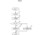
- FIG. 3 is a flowchart for explaining the determination process performed by the control unit 35.
- the determination process is executed at every predetermined timing.
- the welding power source device 1 transmits a welding condition parameter signal to the remote control device 3 for each transmission cycle, and the storage unit 32 stores the welding condition parameter signal as a welding condition parameter Wp.
- storage part 32 is acquired (S1).
- the storage unit 32 also stores a welding condition Wr set by the remote operation device 3.
- the welding condition Wr stored in the storage unit 32 is acquired (S2).
- the welding condition parameter Wp matches the welding condition Wr (S3).
- the elements (set voltage, set current, etc.) of the welding condition parameter Wp all match the corresponding elements of the welding condition Wr, it is determined that the welding condition parameter Wp matches the welding condition Wr.
- the welding condition parameter Wp is set in the welding power source device 1 based on the welding condition Wr set by the remote operation device 3. If communication is correctly performed between the remote control device 3 and the welding power source device 1, the welding condition parameter Wp and the welding condition Wr match.
- the notification unit 34 does not notify when a coincidence signal (low level signal) is input, but when a disagreement signal (high level signal) is input, the notification unit 34 notifies, for example, by a sound of “pea”. I do. Thereby, the welding worker can notice that communication is not performed correctly. In this case, since welding may become unstable and welding quality may deteriorate, the welding operator waits for the communication state to improve without starting the welding operation.
- the result of the determination process is also output to the display unit 33.
- the display unit 33 displays “x” in the communication status column when a mismatch signal (high level signal) is input, and displays in the communication status column when a match signal (eg, low level signal) is input. “ ⁇ ” is displayed (see FIG. 2).
- step S5 only when the determination of NO in step S3 continues for a predetermined number of times (for example, 10 times) or more, and proceeds to step S4 if the determination of NO does not continue for a predetermined number of times or more. Also good.
- step S4 only when the determination of NO in step S3 continues for a predetermined time (for example, 1 second) or longer, the process proceeds to step S5, and when the determination of NO does not continue for a predetermined time or longer, the process proceeds to step S4. Also good.
- a predetermined time for example, 1 second
- the communication unit 36 is for performing wireless communication with the wire feeding device 2.
- the communication unit 36 demodulates the signal received from the wire feeding device 2 and outputs the demodulated signal to the control unit 35.
- the signal received from the wire feeding device 2 includes, for example, a detection signal of a welding voltage or welding current detected by a sensor in the welding power supply device 1, a signal indicating the occurrence of abnormality, and a welding condition stored in the storage unit 12.
- the communication unit 36 modulates a signal input from the control unit 35 and transmits the modulated signal to the wire feeding device 2.
- the signal transmitted to the wire feeder 2 includes, for example, an activation signal for instructing activation of the power conversion unit 11 and a welding condition setting signal for transmitting the welding condition Wr stored in the storage unit 32.
- the signal transmitted / received between the welding power supply apparatuses 1 is not limited to what was mentioned above.
- the communication unit 36 transmits and receives signals through the antenna 36a.
- the communication unit 36 performs BPSK (Binary Phase Shift Shift Keying) modulation on the carrier signal in accordance with the signal input from the control unit 35, performs spectrum spread on the modulated signal, converts it to an analog signal, and transmits it as an electromagnetic wave.
- BPSK Binary Phase Shift Shift Keying
- the modulation method is not limited to BPSK modulation, and ASK modulation or FSK modulation may be performed.
- the spread spectrum is not limited to the direct spreading method, and a frequency hopping method may be used. In this embodiment, the spectrum spread is performed. However, the present invention is not limited to this, and the spectrum spread may not be performed.
- the communication unit 36 converts the electromagnetic wave received by the antenna 36 a into a digital signal, performs despreading and filtering, performs demodulation, and outputs the demodulated signal to the control unit 35. Note that the signal transmitted from the remote operation device 3 to the wire feeding device 2 and the signal transmitted from the wire feeding device 2 to the remote operation device 3 use different frequency bands.
- the operation of the welding apparatus A will be described by taking as an example a case where the welding operator operates the remote control device 3 to set the welding condition parameter Wp of the welding power supply device 1.
- the welding operator operates the operation unit 31 of the remote control device 3 to set the welding condition Wr.
- the welding current setting button 31a is labeled “Current”, and each time the upper part of the button is pressed, the value of the set current increases by 1A, and the lower part of the button is set to 1 Each time it is pressed, the set current value decreases by 1A.
- the welding voltage setting button 31b is labeled “Voltage”, and the set voltage increases by 0.1V each time the upper part of the button is pressed, and every time the lower part of the button is pressed once. The set voltage value decreases by 0.1V.
- the welding condition Wr stored in the storage unit 32 is changed by the operation of the operation unit 31.
- the welding condition Wr stored in the storage unit 32 is displayed on the display unit 33.
- the welding operator looks at the display on the display unit 33 and operates the operation unit 31 so as to obtain a desired value.
- the display of other welding conditions Wr is omitted.
- the remote operation device 3 transmits the welding condition Wr stored in the storage unit 32 to the wire feeding device 2 by wireless communication as a welding condition setting signal for each transmission cycle.
- the wire feeding device 2 amplifies the received welding condition setting signal and transmits it to the welding power source device 1 by wire communication via the power cable 41.
- the welding power source device 1 changes the welding condition parameter Wp stored in the storage unit 12 based on the welding condition setting signal received from the wire feeding device 2.
- the welding power source device 1 is controlled based on the welding condition parameter Wp stored in the storage unit 12.
- the welding power source device 1 transmits the welding condition parameter Wp stored in the storage unit 12 to the wire feeding device 2 by wire communication via the power cable 41 as a welding condition parameter signal for each transmission cycle.
- the wire feeding device 2 amplifies the received welding condition parameter signal and transmits it to the remote control device 3 by wireless communication.
- the remote control device 3 changes the welding condition parameter Wp stored in the storage unit 32 based on the welding condition parameter signal received from the wire feeding device 2. Further, the remote operation device 3 performs a determination process at every predetermined timing. That is, it is determined whether or not the communication is correctly performed by determining whether or not the welding condition parameter Wp stored in the storage unit 32 matches the welding condition Wr. The remote control device 3 performs a predetermined display on the display unit 33 according to the determination result, and causes the notification unit 34 to perform a predetermined notification. In the case of FIG. 2, it is determined that the communication is correctly performed, “Communication state: ⁇ ” is displayed on the display unit 33, and the notification by the notification unit 34 is not performed.
- the welding operator can confirm that the welding condition Wr displayed on the display unit 33 is correctly set as the welding condition parameter Wp of the welding power source device 1 by displaying “communication state: ⁇ ”. If “communication state: ⁇ ” is displayed, it is determined that the welding condition parameter Wp of the welding power source apparatus 1 is set with a content different from the welding condition Wr displayed on the display unit 33. The worker can recognize.
- the remote control device 3 and the wire feeding device 2 perform wireless communication, and the wire feeding device 2 and the welding power source device 1 perform wired communication via the power cable 41. Since the remote control device 3 is located near the wire feeding device 2, there is little possibility that a partition wall or other welding device exists between them, and it is difficult for a failure to occur in wireless communication. Further, since the wire feeding device 2 and the welding power supply device 1 are wired communication, even if they are separated from each other, it is difficult for a communication failure to occur. Therefore, as compared with the case where the remote control device 3 directly performs wireless communication with the welding power source device 1, communication is less likely to occur and communication can be performed accurately.
- the remote operation device 3 performs a determination process, and if the communication with the welding power source device 1 cannot be performed correctly, the remote operator 3 notifies the welding operator to that effect. Therefore, when a failure occurs in communication, the welding operation can be started as it is, and it can be suppressed that welding becomes unstable and the welding quality is deteriorated.
- welding conditions included the setting voltage and the setting current may not include any one of the set voltage and the set current. Further, the welding condition may be such that neither the set voltage nor the set current is included.
- the welding conditions are stored in the storage unit 12 of the welding power source device 1 as a pattern in which the set voltage, the set current, and other conditions are combined, and the remote control device 3 transmits and receives only the pattern number as the welding condition. You may do it.
- the welding power source apparatus 1 is a DC power source that supplies DC power
- the welding power source device 1 may be an AC power source that supplies AC power.
- an inverter circuit may be further added to the power conversion unit 11 so that DC power output from the rectifier circuit is converted into AC power and output.
- the present invention is not limited to this.
- the transmission signal may be transmitted as a voltage signal through the power cable 41, and the voltage signal transmitted through the power cable 41 may be detected.
- the welding power source device 1 and the remote control device 3 perform only communication for relaying the wire feeding device 2 has been described.
- the present invention is not limited to this.
- the welding power supply device 1 and the remote control device 3 may directly communicate with each other.
- a case where direct communication is also performed will be described below as a second embodiment.
- FIG. 4 is a diagram for explaining the overall configuration of the welding apparatus according to the second embodiment.
- symbol is attached
- the welding apparatus A2 shown in FIG. 4 is the first embodiment in that the welding power source apparatus 1 ′ includes the wireless communication unit 15, and the wireless communication unit 15 directly performs wireless communication with the communication unit 36 of the remote control device 3. Different from the welding apparatus A according to FIG.
- the wireless communication unit 15 is for performing wireless communication with the remote control device 3, and transmits and receives signals via an antenna.
- the communication method of the wireless communication unit 15 is common to the communication method of the communication unit 14 except that the communication method is wireless communication.
- the welding power supply device 1 ′ has two communication paths in communication with the remote control device 3.
- the wireless communication unit 15 directly transmits the same signal as the signal transmitted from the communication unit 14 to the remote operation device 3 via the wire feeding device 2 to the remote operation device 3 by wireless communication.
- the signal transmitted by the remote control device 3 is received by the communication unit 14 via the wire feeding device 2 and also received by the wireless communication unit 15.
- the control unit 13 ′ compares the signal received by the communication unit 14 and the signal received by the wireless communication unit 15, and accepts the same signal and performs a predetermined process only when the two match. If they do not match, request retransmission of the signal.
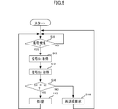
- FIG. 5 is a flowchart for explaining a comparison process performed by the control unit 13 ′ of the welding power source apparatus 1 ′.
- the comparison process is started when the welding power supply apparatus 1 'is activated.
- step S11 it is determined whether or not the communication unit 14 and the wireless communication unit 15 have received a signal (S11). Determination of step S11 until a signal is received is repeated, if the signal is received: the (S11 YES), signals S 1 to the communication unit 14 has received is acquired (S12), the wireless communication unit 15 has received signal S 2 is obtained (S13).
- step S14 whether or not the signals S 1 and the signal S 2 match is determined. If they match (S14: YES), in either of the two communication paths may not communication failure occurs, the signal S 1 and the signal S 2 received is considered to be communicated correctly, the signal Processing according to S 1 (or signal S 2 ) is performed (S15), and the process returns to step S11.
- the signals S 1 and S 2 are welding condition setting signals
- the welding condition parameter Wp in the storage unit 12 is changed.
- the signals S 1 and S 2 are activation signals
- the power conversion unit 11 is activated.
- the processing is performed (S15), the reception waiting state of the next signal (S11) become. If the signals S 1 and the signal S 2 match (S14: NO), and retransmission is requested (S16), it waits for a signal to be retransmitted (S11).
- the welding power source apparatus 1 ′ since the welding power source apparatus 1 ′ performs processing only when the signals received through the two communication paths match, the signal received when the communication failure has occurred and communication has not been performed correctly. It is possible to prevent the processing based on this.
- FIG. 6 is a flowchart for explaining another embodiment of the comparison process performed by the control unit 13 ′ of the welding power source apparatus 1 ′.
- steps S21 to S24 are added to the flowchart shown in FIG. 5, and step S15 is changed to S15 ′.
- step S23 by counting the number of comparisons N (step S23), it is determined whether or not exceeded the predetermined number N 0 (S22), if it exceeds (S22: YES), and depending on the signals S 1 Processing is performed (S15 ').
- Steps S21 and S24 are steps for initializing the number N of comparisons to “1”.
- steps S22, S16, S23, S11 to S14 are repeated, and the number of comparisons N is counted. If the comparison number N has exceeded the predetermined number N 0 (S22: YES), the processing corresponding to the signal S 1 is performed (S15 '), comparing the number N is initialized to "1" (S24), the following (S11).
- the wireless communication unit 15 performs wireless communication with the remote operation device 3, whereas the communication unit 14 performs wired communication with the wire feeding device 2, and the wire feeding device 2 and the remote operation device 3. Wireless communication is performed at a location close to. Therefore, the signal S 1 received by the communication unit 14 is more reliable than the signal S 2 received by the wireless communication unit 15. Therefore, in step S15 ', and to perform the processing according to the signal S 1.
- the reliability is lower than the case where the retransmission request is made until the signal S 1 and the signal S 2 match, but the time until the process is performed can be shortened.
- the comparison number N exceeds the predetermined number N 0 (S22: YES)
- a signal for alerting the remote control device 3 may be transmitted. If the remote control device 3 that has received the signal notifies the attention, it is possible to alert the welding operator that there is a possibility of communication failure.
- the process according to the signal S 1 may be performed without requesting retransmission.
- the flowchart in this case is obtained by replacing step S16 with step S15 ′ in the flowchart shown in FIG.
- the reliability is further lowered, but the time until the processing is performed can be further shortened.
- control unit 35 of the remote operation device 3 may have the same function. That is, the control unit 35 compares the signal directly received by the communication unit 36 from the wireless communication unit 15 with the signal received by the communication unit 36 after being relayed by the relay unit 21, and if both match, A signal may be received and processed, and if they do not match, a retransmission of the signal may be requested.
- the present invention is not limited to this.
- the wire feeding device 2 in the case of a non-consumable electrode type welding device, the wire feeding device 2 is not used.
- the welding torch T may be provided with a relay function so that the welding torch T relays communication.
- the case of a non-consumable electrode type welding apparatus will be described below as a third embodiment.
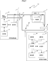
- FIG. 7 is a diagram for explaining the overall configuration of the welding apparatus according to the third embodiment.
- symbol is attached
- the welding apparatus T ′ differs from the welding apparatus A according to the first embodiment in that the welding apparatus A3 illustrated in FIG. 7 does not include the wireless feeding device, and the welding torch T ′ includes the relay unit 21.
- the relay unit 21 has the same configuration and the same function as the relay unit 21 of the wire feeding device 2 according to the first embodiment.
- the welding torch T ′ performs wired communication with the welding power source device 1 via the power cable 41 and wireless communication with the remote control device 3.
- the welding torch T ' has a relay function for amplifying and transmitting the received signal. Further, since the welding torch T 'is used by a welding operator by hand, the welding torch T' and the remote control device 3 are located close to each other. Therefore, also in the third embodiment, the same effect as in the first embodiment can be obtained.
- a relay device including the relay unit 21 may be separately provided.
- the case where the relay device 5 is provided in the middle of the power cable 41 will be described below as a fourth embodiment.
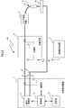
- FIG. 8 is a diagram for explaining the overall configuration of the welding apparatus according to the fourth embodiment.
- symbol is attached
- the welding device A4 shown in FIG. 8 is the first in that the relay unit 21 is not provided in the wireless feeding device 2 ′, and the relay device 5 including the relay unit 21 is provided in the middle of the power cable 41. It is different from the welding apparatus A according to one embodiment.
- the relay unit 21 has the same configuration and the same function as the relay unit 21 of the wire feeding device 2 according to the first embodiment.
- the relay device 5 performs wired communication with the welding power source device 1 via the power cable 41 and performs wireless communication with the remote control device 3.
- the relay device 5 has a relay function for amplifying and transmitting the received signal.
- the relay device 5 can be provided at an arbitrary position of the power cable 41, but it is preferable to provide the relay device 5 as close to the remote operation device 3 as possible so that wireless communication with the remote operation device 3 can be easily performed.
- the relay device 5 may be arranged so as to be movable on the power cable 41. In the fourth embodiment, the same effect as that of the first embodiment can be obtained.
- the welding apparatus and the communication method of the welding apparatus according to the present invention are not limited to the above-described embodiment.
- the specific configuration of each part of the welding apparatus and the communication method of the welding apparatus according to the present invention can be varied in design in various ways.
Landscapes
- Engineering & Computer Science (AREA)
- Physics & Mathematics (AREA)
- Plasma & Fusion (AREA)
- Mechanical Engineering (AREA)
- Power Engineering (AREA)
- Computer Networks & Wireless Communication (AREA)
- Signal Processing (AREA)
- Arc Welding Control (AREA)
- Cable Transmission Systems, Equalization Of Radio And Reduction Of Echo (AREA)
Abstract
無線通信を利用する遠隔操作装置が溶接電源装置との間で適切に通信を行うことができる溶接装置を提供する。この溶接装置は、溶接電源装置と、この溶接電源装置とパワーケーブルで接続されるワイヤ送給装置と、このワイヤ送給装置との間で無線通信を行う遠隔操作装置と、を備えている。前記溶接電源装置と前記ワイヤ送給装置とは、前記パワーケーブルを介して通信を行う。前記遠隔操作装置は前記ワイヤ送給装置の近くに位置される。前記ワイヤ送給装置と前記溶接電源装置とは、有線通信により適切な通信が行われる。
Description
本発明は、遠隔操作装置で溶接電源装置の操作を行う溶接装置に関する。また本発明は、このような溶接装置の通信方法に関する。
消耗電極式の溶接装置は、溶接に必要な電力を供給するための溶接電源装置や、ワイヤ送給装置などを含んでいる。溶接電源装置は重量があるため、所定の箇所に設置して使用される。一方、ワイヤ送給装置は、溶接個所の変更に伴って、溶接作業者により持ち運びされる。溶接電源装置が溶接作業を行っている位置から離れた場所にある場合、溶接条件(たとえば溶接電圧値)を設定するためには、作業者が溶接電源装置の設置場所まで移動しなければならず、作業効率が悪くなる。この不具合を改善するために、溶接電源装置との間で無線通信を行う遠隔操作装置を用いて、溶接条件の変更を行うものが提案されている(特許文献1参照)。
造船、橋梁等の大型構造物の溶接現場においては、溶接電源装置と溶接個所とが数十m離れていることもある。このような溶接現場では、溶接電源装置に対し、無線式の遠隔操作装置により溶接条件の設定ができれば非常に便利である。しかしながら、遠隔操作装置と溶接電源装置との間に隔壁などが存在すると、無線通信に障害が生じることがある。
また、大型構造物の溶接現場においては、複数の溶接装置が用いられることがある。このような場合、一の溶接装置に対する無線信号に対し、他の溶接装置に対する無線信号が混信したり、ノイズが混入するなどの不具合が生じることがある。
図9を参照して、より具体的に説明する。同図は、従来の溶接装置A100の遠隔操作装置300と溶接電源装置100との間で、無線通信を行っている状態を示している。溶接電源装置100は被加工物Wから離れた位置に配置されており、ワイヤ送給装置200は被加工物Wの近くに配置されている。溶接作業者は溶接電源装置100を遠隔操作するための遠隔操作装置300を所持している。同図に示すように、溶接電源装置100と遠隔操作装置300との間に隔壁Bがあると、遠隔操作装置300の通信部360から出力された信号が、溶接電源装置100の通信部140に正しく受信されないおそれがある。また、遠隔操作装置300と溶接電源装置100とが離れているので、間にある他の溶接装置の送信信号を受信したり、他の機器から発生したノイズが混入したりする場合がある。
上記のように無線通信に障害が発生すると、遠隔操作装置300で設定された溶接条件が溶接電源装置100に正確に通信されないため、溶接が不安定になり、溶接品質が悪くなる。
本発明は上記した事情のもとで考え出されたものである。そこで本発明は、無線通信を利用する遠隔操作装置と溶接電源装置との間において、正確に通信を行うことができる溶接装置を提供することをその目的としている。
上記課題を解決するため、本発明では、次の技術的手段を講じている。
本発明の第1の側面によって提供される溶接装置は、溶接電源装置と、前記溶接電源装置に接続された電力伝送線と、前記電力伝送線上に設けられた中継装置と、前記中継装置との間で無線通信を行う遠隔操作装置と、を備えている。前記溶接電源装置と前記中継装置とは、前記電力伝送線を介して通信を行う構成とされている。
本発明の第2の側面によれば、前記第1の側面に係る溶接装置において、前記溶接電源装置は、前記遠隔操作装置との間で無線通信を行うよう構成されている。また、前記溶接電源装置は、無線通信によって前記遠隔操作装置から直接受信した直接信号と、前記中継装置および前記電力伝送線を介して受信した間接信号とを比較する比較手段と、前記比較手段によって前記直接信号および前記間接信号が同じであると判断された場合に、所定の処理を行う処理手段と、を備えている。
本発明の第3の側面によれば、前記第2の側面に係る溶接装置において、前記溶接電源装置は、前記比較手段によって前記直接信号および前記間接信号が異なると判断された場合に、前記遠隔操作装置に信号の再送信を要求する再送信要求手段を備えている。
本発明の第4の側面によれば、前記第3の側面に係る溶接装置において、前記溶接電源装置は、前記比較手段が比較を行った回数をカウントするカウント手段を備えている。また、前記処理手段は、前記カウント手段によってカウントされた数が所定数を超えた場合に、前記中継装置および前記電力伝送線を介して受信した信号に基づいて処理を行うよう構成されている。
本発明の第5の側面によれば、前記第2の側面に係る溶接装置において、前記処理手段は、前記比較手段によって前記直接信号および前記間接信号が異なると判断された場合に、前記中継装置および前記電力伝送線を介して受信した信号に基づいて処理を行うよう構成されている。
本発明の第6の側面によれば、前記第1~第5の側面に係る溶接装置において、前記溶接電源装置は、溶接条件を設定するための溶接条件設定信号を受信する第1通信手段と、前記第1通信手段によって受信された前記溶接条件設定信号に基づいて、第1記憶手段に記憶されている溶接条件パラメータを変更する第1記憶制御手段と、前記第1記憶手段に記憶されている前記溶接条件パラメータに基づいて、前記溶接電源装置の出力を制御する出力制御手段と、を備えている。前記第1通信手段は、前記第1記憶手段に記憶されている前記溶接条件パラメータを溶接条件パラメータ信号として送信するよう構成されている。また、前記遠隔制御装置は、溶接作業者による操作に基づいて、第2記憶手段に記憶されている溶接条件を変更する第2記憶制御手段と、前記第2記憶手段に記憶されている前記溶接条件に基づいて表示を行う表示手段と、前記第2記憶手段に記憶されている前記溶接条件を溶接条件信号として送信し、前記第1通信手段が送信した溶接条件パラメータ信号を受信する第2通信手段と、前記第2通信手段によって受信された前記溶接条件パラメータ信号に基づく溶接条件パラメータを記憶する第3記憶手段と、前記第2記憶手段に記憶されている前記溶接条件と前記第3記憶手段に記憶されている前記溶接条件パラメータとを比較して、一致しているか否かを判定する判定手段と、前記判定手段による判定結果に基づいて所定の報知を行う報知手段と、を備えている。
本発明の第7の側面によれば、前記第1~第6の側面に係る溶接装置において、前記中継装置はワイヤ送給装置である。
本発明の第8の側面によれば、前記第1~第6の側面に係る溶接装置において、前記中継装置は溶接トーチである。
本発明の第9の側面によれば、溶接装置に用いられる中継装置が提供される。この中継装置は、溶接電源装置が電力を供給するための電力伝送線上に設けられる。また、前記中継装置は、前記溶接電源装置を遠隔操作するための遠隔操作装置との間で無線通信を行うよう構成されているとともに、前記溶接電源装置との間で前記電力伝送線を介した通信を行うように構成されている。
本発明の第10の側面によれば、溶接電源装置と、前記溶接電源装置が電力を供給するための電力伝送線と、前記電力伝送線上に設けられている中継装置と、前記溶接電源装置を遠隔操作するための遠隔操作装置とを備えている溶接装置の通信方法が提供される。この通信方法は、前記遠隔操作装置が、無線によって信号を送信する第1の工程と、前記中継装置が、前記遠隔操作装置が送信した信号を受信する第2の工程と、前記中継装置が、受信した信号を、前記電力伝送線を介して前記溶接電源装置に送信する第3の工程と、前記溶接電源装置が、前記電力伝送線を介して送信された信号を受信する第4の工程と、を備えている。
本発明によると、遠隔操作装置とワイヤ送給装置とが無線通信を行い、ワイヤ送給装置と溶接電源装置とが電力伝送線を介した有線通信を行う。遠隔操作装置はワイヤ送給装置の近くに位置するので、間に隔壁やほかの溶接装置などが存在する可能性が少なく、無線通信に障害が発生しにくい。また、ワイヤ送給装置と溶接電源装置とは有線通信なので、たとえ互いに離れていても通信に障害が発生しにくい。したがって、従来のように遠隔操作装置が溶接電源装置と直接無線通信を行う場合と比べて、通信に障害が発生しにくく、より正確に通信を行うことができる。
本発明のその他の特徴および利点は、添付図面を参照して以下に行う詳細な説明によって、より明らかとなろう。
以下、本発明の実施の形態を、図面を参照して具体的に説明する。
図1は、第1実施形態に係る溶接装置の全体構成を説明するための図である。
図1に示すように、溶接装置Aは、溶接電源装置1、ワイヤ送給装置2、遠隔操作装置3、2本のパワーケーブル41,42、および、溶接トーチTを備えている。溶接電源装置1は2つの出力端子を備えており、一方の出力端子は、パワーケーブル41を介して、ワイヤ送給装置2に接続されている。ワイヤ送給装置2は、ワイヤ電極を溶接トーチTに送り出して、ワイヤ電極の先端を溶接トーチTの先端から突出させる。ワイヤ送給装置2において、パワーケーブル41とワイヤ電極とは電気的に接続されている。溶接電源装置1の他方の出力端子は、パワーケーブル42を介して、被加工物Wに接続される。溶接電源装置1は、溶接トーチTの先端から突出するワイヤ電極の先端と、被加工物Wとの間に高電圧を印加してアークを発生させ、当該アークの熱により被加工物Wの溶接が行われる。なお、溶接装置Aは、必要に応じて、溶接トーチTから放出するためのシールドガスのガスタンク、溶接トーチTを冷却する冷却水を循環させる冷却水循環装置などを備えていてもよい。
溶接電源装置1は、アークを発生させるための電力を供給するものである。溶接電源装置1は、電力変換部11、記憶部12、制御部13、および、通信部14を備えている。
電力変換部11は、外部の電力系統から入力される三相交流電力をアーク溶接に適した直流電力に変換して出力するものである。電力変換部11に入力される三相交流電力は、整流回路によって直流電力に変換され、インバータ回路によって交流電力に変換される。そして、トランスによって昇圧され、整流回路によって直流電力に変換されて出力される。なお、電力変換部11の構成は、上記したものに限定されない。
記憶部12は、溶接電源装置1から出力される溶接電圧を設定するための設定電圧や、溶接電源装置1から出力される溶接電流を設定するための設定電流などの溶接条件パラメータWpを記憶するものである。
制御部13は、溶接電源装置1の制御を行うものであり、例えばマイクロコンピュータなどによって実現されている。制御部13は、溶接電源装置1から出力される溶接電圧や溶接電流が記憶部12に記憶されている設定電圧や設定電流になるように、制御を行う。また、設定ボタン(図示略)の操作に応じて記憶部12に記憶されている溶接条件パラメータWpの変更を行ったり、起動ボタン(図示略)の操作に応じて電力変換部11を起動させたりなどの制御を行う。また、制御部13は、センサ(図示略)によって検出された溶接電圧や溶接電流の検出値を表示部(図示略)に表示させたり、異常が発生した場合に報知部(図示略)に報知させたりする。
また、制御部13は、通信部14から入力される信号に基づいても、溶接条件パラメータWpの変更や電力変換部11の起動を行い、検出された溶接電圧または溶接電流の検出信号や、異常発生を示す信号を通信部14に出力する。また、制御部13は、あらかじめ設定された送信周期ごとに、記憶部12に記憶されている溶接条件パラメータWpを読み出して、通信部14に出力する。本実施形態では、送信周期は、10~500ms程度の範囲で設定されている。
通信部14は、パワーケーブル41を介して、ワイヤ送給装置2との間で通信を行うためのものである。通信部14は、ワイヤ送給装置2から受信した信号を復調して、制御部13に出力する。ワイヤ送給装置2から受信する信号には、例えば、記憶部12に記憶された溶接条件パラメータWpを変更するための溶接条件設定信号や、電力変換部11の起動を指示する起動信号などがある。また、通信部14は、制御部13から入力される信号を変調して、ワイヤ送給装置2に送信する。ワイヤ送給装置2に送信する信号には、例えば、検出された溶接電圧または溶接電流の検出信号や、異常発生を示す信号、記憶部12に記憶されている溶接条件パラメータWpを送信するための溶接条件パラメータ信号などがある。なお、ワイヤ送給装置2との間で送受信される信号は、上記したものに限定されない。
通信部14は、直接スペクトル拡散(Direct Sequence Spread Spectrum: DSSS)通信方式を用いて通信を行う。直接スペクトル拡散通信方式では、送信側は、送信する信号に対して拡散符号による演算を行い、元の信号のスペクトルをより広い帯域に拡散して送信する。受信側は、受信した信号を共通する拡散符号を用いて逆拡散することで、元の信号に戻す。溶接装置毎に異なる拡散符号を用いていれば、別の溶接装置で送受信される信号を受信したとしても、当該信号は異なる拡散符号で逆拡散されて、ノイズとして除去される。したがって、高い通信品質で通信を行うことができる。
通信部14は、パワーケーブル41の周囲に配置されてパワーケーブル41に磁気結合したコイルを備えている。通信部14は、当該コイルを介して、信号をパワーケーブル41で送信し、また、パワーケーブル41で送られる信号を当該コイルによって検出する。通信部14は、制御部13より入力される信号に応じてキャリア信号をBPSK(Binary Phase Shift Keying)変調し、変調信号にスペクトル拡散を行い、アナログ信号に変換して送信する。なお、変調方法はBPSK変調に限られず、ASK変調やFSK変調を行うようにしてもよい。また、スペクトル拡散は直接拡散方式に限られず、周波数ホッピング方式を用いてもよい。なお、本実施形態では、スペクトル拡散を行っているが、これに限定されず、スペクトル拡散を行わないようにしてもよい。通信部14は、パワーケーブル41で送られる信号をコイルによって検出し、デジタル信号に変換して、逆拡散およびフィルタリングを行い、復調を行って、制御部13に出力する。なお、溶接電源装置1からワイヤ送給装置2に送信する信号と、ワイヤ送給装置2から溶接電源装置1に送信する信号とでは、異なる周波数帯域を利用している。
ワイヤ送給装置2は、ワイヤ電極を溶接トーチTに送り出すものである。ワイヤ送給装置2は、送給モータ(図示略)を制御して、ワイヤ電極の送り出しを行う。また、ワイヤ送給装置2は、溶接電源装置1と遠隔操作装置3との通信を中継する機能も有しており、中継部21を備えている。
中継部21は、溶接電源装置1と遠隔操作装置3との通信を中継するものである。中継部21は、溶接電源装置1との間でパワーケーブル41を介した有線通信を行い、遠隔操作装置3との間で無線通信を行う。中継部21は、溶接電源装置1が送信した信号を、パワーケーブル41の周囲に配置されたコイルによって検出し、検出した信号を増幅して、アンテナによって電磁波として遠隔操作装置3に送信する。また、中継部21は、遠隔操作装置3が出力する電磁波をアンテナで受信し、受信した信号を増幅して、コイルを介して、パワーケーブル41で送信する。なお、中継部21は、受信した信号を増幅することなく、そのまま送信するようにしてもよい。また、中継部21が受信した信号を一旦復調して、所定の処理を行った上で変調して送信するようにしてもよい。例えば、溶接電源装置1から送信した信号でワイヤ送給装置2を制御する場合は、中継部21での復調および変調が必要になる。
遠隔操作装置3は、離れた位置から溶接電源装置1を操作するためのものである。遠隔操作装置3は、溶接電源装置1の電力変換部11を起動したり、溶接電源装置1の溶接条件パラメータWpの変更を行ったりする。また、溶接電源装置1で検出された溶接電圧または溶接電流の検出値を表示したり、溶接電源装置1で発生した異常を報知したりする。遠隔操作装置3は、操作部31、記憶部32、表示部33、報知部34、制御部35、および、通信部36を備えている。
操作部31は、溶接作業者による操作ボタンの操作を操作信号として制御部35に出力するものである。
図2は、遠隔操作装置3の外観の一例を示す。同図に示すように、遠隔操作装置3の操作部31には、操作ボタンとして、溶接電流設定用ボタン31a、溶接電圧設定用ボタン31b、および、起動ボタン31cが配置されている。溶接電流設定用ボタン31aは、溶接電源装置1から出力される溶接電流の設定電流を変更するためのものである。溶接電圧設定用ボタン31bは、溶接電源装置1から出力される溶接電圧の設定電圧を変更するためのものである。起動ボタン31cは、溶接電源装置1の電力変換部11を起動させるためのものである。溶接電流設定用ボタン31aまたは溶接電圧設定用ボタン31bが操作されると、操作部31は、溶接条件を変更するための操作信号を、制御部35に出力する。起動ボタン31cが操作されると、操作部31は、起動のための操作信号を、制御部35に出力する。なお、操作部31には、他の操作ボタンが配置されていてもよい。各操作ボタンの操作の詳細については後述する。
図1に戻って、記憶部32は、操作部31の操作ボタンの操作によって設定される溶接条件Wrを記憶するものである。また、記憶部32は、溶接電源装置1から溶接条件パラメータ信号として受信した溶接条件パラメータWpも記憶している。記憶部32は、溶接条件Wrと溶接条件パラメータWpとを、それぞれ定められた記憶領域に記憶している。
表示部33は、各種表示を行うものであり(図2参照)、例えば液晶表示装置によって実現されている。表示部33は、制御部35によって制御されており、記憶部32に記憶されている溶接条件Wrを表示し、後述する判定処理の結果も表示する。また、溶接電源装置1で検出された溶接電圧や溶接電流の検出値の表示も行う。
報知部34は、所定の報知を行うものであり、例えばスピーカによって実現されている。報知部34は、制御部35によって制御されており、溶接電源装置1の異常を警告音で報知する。また、後述する判定処理の結果も報知する。なお、報知部34は、音で報知を行うものに限定されない。例えば、振動で報知を行うようにしてもよいし、表示部33に文字や画像で報知するようにしてもよい。
制御部35は、遠隔操作装置3の制御を行うものであり、例えばマイクロコンピュータなどによって実現されている。制御部35は、操作部31より入力される起動のための操作信号に応じて、溶接電源装置1の電力変換部11を起動するための起動信号を通信部36に出力する。また、操作部31より入力される溶接条件Wrを変更するための操作信号に応じて、記憶部32に記憶されている溶接条件Wrを変更する。
また、制御部35は、あらかじめ設定された送信周期ごとに、記憶部32に記憶されている溶接条件Wrを読み出して、通信部36および表示部34に出力する。なお、本実施形態では、送信周期は、10~500ms程度の範囲で設定されている。制御部35に設定される送信周期は、溶接電源装置1の制御部13に設定される送信周期と同じであってもよいし、異なっていてもよい。また、送信周期に係わらず、記憶部32に記憶されている溶接条件Wrが変更された時に、変更後の溶接条件Wrを出力するようにしてもよい。
また、制御部35は、通信部36より入力される溶接電圧または溶接電流の検出値を、表示部33に出力して表示させたり、通信部36より入力される異常発生を示す信号に基づいて、報知部34に異常の報知をさせたりする。
また、制御部35は、遠隔操作装置3で設定された溶接条件Wrが溶接電源装置1に正しく通信されているかを判定する判定処理を行う。
図3は、制御部35が行う判定処理を説明するためのフローチャートである。当該判定処理は、所定のタイミング毎に実行される。
上述したように、溶接電源装置1は送信周期ごとに溶接条件パラメータ信号を遠隔操作装置3に送信しており、記憶部32は溶接条件パラメータWpとして記憶している。まず、記憶部32に記憶されている溶接条件パラメータWpが取得される(S1)。また、記憶部32は、遠隔操作装置3で設定された溶接条件Wrも記憶している。記憶部32に記憶されている溶接条件Wrが取得される(S2)。
次に、溶接条件パラメータWpが溶接条件Wrに一致するか否かが判別される(S3)。溶接条件パラメータWpの各要素(設定電圧や設定電流など)が溶接条件Wrの対応する各要素にすべて一致する場合に、溶接条件パラメータWpが溶接条件Wrに一致すると判別される。溶接条件パラメータWpは、遠隔操作装置3で設定された溶接条件Wrに基づいて溶接電源装置1に設定されたものである。遠隔操作装置3と溶接電源装置1との間で正しく通信が行われていれば、溶接条件パラメータWpと溶接条件Wrとは一致する。溶接条件パラメータWpと溶接条件Wrとが一致する場合(S3:YES)、正しく通信が行われており、遠隔操作装置3で設定された溶接条件Wrが溶接条件パラメータWpとして溶接電源装置1に正しく設定されていると判定され、一致信号(例えば、ローレベル信号)が報知部34に出力されて(S4)、判定処理が終了する。
一方、溶接条件パラメータWpと溶接条件Wrとが一致しない場合(S3:NO)、正しく通信が行われておらず、遠隔操作装置3で設定された溶接条件Wrが溶接電源装置1に正しく設定されていないと判定され、不一致信号(例えば、ハイレベル信号)が報知部34に出力されて(S5)、判定処理が終了する。
報知部34は、一致信号(ローレベル信号)が入力された場合には報知を行わないが、不一致信号(ハイレベル信号)が入力された場合には、例えば、「ピー」という音声によって、報知を行う。これにより、溶接作業者は、通信が正しく行われていないことに気付くことができる。この場合、溶接が不安定になり溶接品質が悪くなる可能性があるので、溶接作業者は溶接作業を開始せずに、通信状態が改善されるのを待つ。また、本実施形態では、判定処理の結果は表示部33にも出力される。表示部33は、不一致信号(ハイレベル信号)が入力された場合に通信状態の欄に「×」を表示し、一致信号(例えば、ローレベル信号)が入力された場合に通信状態の欄に「○」を表示する(図2参照)。
なお、判定処理のフローチャートは、図3に示したものに限定されない。例えば、ステップS3でNOとの判別が所定回数(例えば、10回)以上連続している場合にのみ、ステップS5に進み、NOとの判別が所定回数以上連続しない場合にはステップS4に進むようにしてもよい。また、ステップS3でNOとの判別が所定時間(例えば、1秒)以上連続している場合にのみ、ステップS5に進み、NOとの判別が所定時間以上連続しない場合にはステップS4に進むようにしてもよい。溶接作業者が溶接条件を設定している途中には、通信による時間遅れによって、WpとWrとが一致しない瞬間が発生する場合がある。この瞬間的な不一致の場合にも報知が行われると紛らわしいので、所定回数(または、所定時間)以上連続してNOと判別されることで判定を行っている。
通信部36は、ワイヤ送給装置2との間で無線通信を行うためのものである。通信部36は、ワイヤ送給装置2から受信した信号を復調して、制御部35に出力する。ワイヤ送給装置2から受信する信号には、例えば、溶接電源装置1においてセンサで検出された溶接電圧または溶接電流の検出信号や、異常発生を示す信号、記憶部12に記憶されている溶接条件パラメータWpに基づいて送信された溶接条件パラメータ信号などがある。また、通信部36は、制御部35から入力される信号を変調して、ワイヤ送給装置2に送信する。ワイヤ送給装置2に送信する信号には、例えば、電力変換部11の起動を指示する起動信号や、記憶部32に記憶された溶接条件Wrを送信するための溶接条件設定信号などがある。なお、溶接電源装置1との間で送受信される信号は、上記したものに限定されない。
通信部36は、アンテナ36aを介して信号の送受信を行う。通信部36は、制御部35より入力される信号に応じてキャリア信号をBPSK(Binary Phase Shift Keying)変調し、変調信号にスペクトル拡散を行い、アナログ信号に変換して、電磁波として送信する。なお、変調方法はBPSK変調に限られず、ASK変調やFSK変調を行うようにしてもよい。また、スペクトル拡散は直接拡散方式に限られず、周波数ホッピング方式を用いてもよい。なお、本実施形態では、スペクトル拡散を行っているが、これに限定されず、スペクトル拡散を行わないようにしてもよい。通信部36は、アンテナ36aが受信した電磁波をデジタル信号に変換して、逆拡散およびフィルタリングを行い、復調を行って、制御部35に出力する。なお、遠隔操作装置3からワイヤ送給装置2に送信する信号と、ワイヤ送給装置2から遠隔操作装置3に送信する信号とでは、異なる周波数帯域を利用している。
次に、溶接作業者が遠隔操作装置3を操作して、溶接電源装置1の溶接条件パラメータWpを設定する場合を例として、溶接装置Aの作用について説明する。
溶接作業者は、遠隔操作装置3の操作部31を操作して溶接条件Wrを設定する。図2に示すように、溶接電流設定用ボタン31aには「Current」とラベルが付されており、ボタンの上部を1回押すごとに設定電流の値が1Aずつ増加し、ボタンの下部を1回押すごとに設定電流の値が1Aずつ減少する。また、溶接電圧設定用ボタン31bには「Voltage」とラベルが付されており、ボタンの上部を1回押すごとに設定電圧の値が0.1Vずつ増加し、ボタンの下部を1回押すごとに設定電圧の値が0.1Vずつ減少する。操作部31の操作によって、記憶部32に記憶されている溶接条件Wrが変更される。記憶部32に記憶されている溶接条件Wrは、表示部33に表示される。図2においては、現在の溶接条件Wrの一部である「設定電流:150A」および「設定電圧:18.5V」が表示されている。溶接作業者は、表示部33の表示をみて、所望の値になるように操作部31を操作する。なお、同図においては他の溶接条件Wrの表示を省略している。
遠隔操作装置3は、記憶部32に記憶されている溶接条件Wrを、送信周期ごとに溶接条件設定信号として、無線通信によってワイヤ送給装置2に送信する。ワイヤ送給装置2は受信した溶接条件設定信号を増幅して、パワーケーブル41を介した有線通信によって溶接電源装置1に送信する。
溶接電源装置1は、ワイヤ送給装置2から受信した溶接条件設定信号に基づいて、記憶部12に記憶されている溶接条件パラメータWpを変更する。溶接電源装置1は、記憶部12に記憶されている溶接条件パラメータWpに基づいて制御される。
また、溶接電源装置1は、記憶部12に記憶されている溶接条件パラメータWpを、送信周期ごとに溶接条件パラメータ信号として、パワーケーブル41を介した有線通信によってワイヤ送給装置2に送信する。ワイヤ送給装置2は受信した溶接条件パラメータ信号を増幅して、無線通信によって遠隔操作装置3に送信する。
遠隔操作装置3は、ワイヤ送給装置2から受信した溶接条件パラメータ信号に基づいて、記憶部32に記憶されている溶接条件パラメータWpを変更する。また、遠隔操作装置3は、所定のタイミング毎に判定処理を行う。すなわち、記憶部32に記憶されている溶接条件パラメータWpと溶接条件Wrとが一致するか否かを判別して、正しく通信されているかを判定する。遠隔操作装置3は、判定結果に応じて、表示部33に所定の表示を行い、報知部34に所定の報知をさせる。図2の場合は、正しく通信されていると判定されて、表示部33に「通信状態:○」の表示がされており、報知部34による音声での報知はされていない。溶接作業者は、「通信状態:○」の表示により、表示部33に表示されている溶接条件Wrが溶接電源装置1の溶接条件パラメータWpとして正しく設定されていることを確認することができる。もし、「通信状態:×」と表示されていた場合は、表示部33に表示されている溶接条件Wrとは異なる内容で溶接電源装置1の溶接条件パラメータWpが設定されていることを、溶接作業者は認識することができる。
本実施形態によると、遠隔操作装置3とワイヤ送給装置2とが無線通信を行い、ワイヤ送給装置2と溶接電源装置1とがパワーケーブル41を介した有線通信を行う。遠隔操作装置3はワイヤ送給装置2の近くに位置するので、間に隔壁やほかの溶接装置などが存在する可能性が少なく、無線通信に障害が発生しにくい。また、ワイヤ送給装置2と溶接電源装置1とは有線通信なので、たとえ離れていても通信に障害が発生しにくい。したがって、遠隔操作装置3が溶接電源装置1と直接無線通信を行う場合と比べて、通信に障害が発生しにくく、正確に通信を行うことができる。
また、遠隔操作装置3は判定処理を行い、溶接電源装置1との間で正しく通信できなかった場合に、その旨を溶接作業者に知らせる。したがって、通信に障害が発生した場合に、そのまま溶接作業を開始して、溶接が不安定になって溶接品質が悪くなってしまうことを抑制することができる。
なお、本実施形態においては、溶接条件が設定電圧および設定電流を含んでいる場合について説明したが、これに限られない。溶接条件は、設定電圧および設定電流のいずれか一方を含んでいなくてもよい。また、溶接条件が、設定電圧および設定電流のいずれも含まないようにしてもよい。例えば、溶接条件を、設定電圧、設定電流、その他の条件を組み合わせたパターンとして溶接電源装置1の記憶部12に記憶しておき、遠隔操作装置3とはパターンのナンバーだけを溶接条件として送受信するようにしてもよい。
本実施形態においては、溶接電源装置1が直流電力を供給する直流電源である場合について説明したが、これに限られない。例えばアルミなどの溶接を行うために、溶接電源装置1を、交流電力を供給する交流電源としてもよい。この場合、電力変換部11にさらにインバータ回路を追加し、整流回路から出力される直流電力を交流電力に変換して出力するようにすればよい。
本実施形態においては、通信部14および中継部21が、パワーケーブル41の周囲に配置されたコイルによる磁気結合を利用する場合について説明したが、これに限られない。例えば、パワーケーブル41に接続されたコンデンサを用いて、送信信号を電圧信号としてパワーケーブル41で送信し、また、パワーケーブル41で送られる電圧信号を検出するようにしてもよい。
上記第1実施形態においては、溶接電源装置1と遠隔操作装置3とが、ワイヤ送給装置2を中継する通信のみを行う場合について説明したが、これに限られない。例えば、溶接電源装置1と遠隔操作装置3とが直接通信も行うようにしてもよい。直接通信も行う場合を第2実施形態として、以下に説明する。
図4は、第2実施形態に係る溶接装置の全体構成を説明するための図である。同図において、第1実施形態に係る溶接装置A(図1参照)と同一または類似の要素には、同一の符号を付している。
図4に示す溶接装置A2は、溶接電源装置1’が無線通信部15を備えており、無線通信部15が遠隔操作装置3の通信部36と直接無線通信を行う点で、第1実施形態に係る溶接装置Aと異なる。
無線通信部15は、遠隔操作装置3との間で無線通信を行うためのものであり、アンテナを介して信号の送受信を行う。無線通信部15の通信方式は、無線通信であることを除いて、通信部14の通信方式と共通する。溶接電源装置1’は、遠隔操作装置3との通信において、2つの通信経路を有している。無線通信部15は、通信部14がワイヤ送給装置2を経由して遠隔操作装置3に送信する信号と同じ信号を、無線通信により遠隔操作装置3に直接送信する。また、遠隔操作装置3が送信する信号は、ワイヤ送給装置2を経由して通信部14によって受信され、無線通信部15によっても受信される。通信部14が受信した信号(「間接信号」)と、無線通信部15が受信した信号(「直接信号」)とが一致する場合、いずれの通信経路でも通信障害が発生していないと考えることができる。
制御部13’は、通信部14が受信した信号と無線通信部15が受信した信号の比較を行い、両者が一致する場合にのみ、この同じ信号を受け付けて所定の処理を行う。一致しない場合は、信号の再送信を要求する。
図5は、溶接電源装置1’の制御部13’が行う比較処理を説明するためのフローチャートである。当該比較処理は、溶接電源装置1’が起動されたときに開始される。
まず、通信部14および無線通信部15が信号を受信したか否かが判別される(S11)。信号が受信されるまでステップS11の判別は繰り返され、信号が受信された場合(S11:YES)に、通信部14が受信した信号S1が取得され(S12)、無線通信部15が受信した信号S2が取得される(S13)。
次に、信号S1と信号S2とが一致するか否かが判別される(S14)。一致する場合(S14:YES)、2つの通信経路のいずれにも通信障害が発生しておらず、受信された信号S1および信号S2は正しく通信されたものであると考えられるので、信号S1(または信号S2)に応じた処理が行われて(S15)、ステップS11に戻る。例えば、信号S1,S2が溶接条件設定信号であった場合、記憶部12の溶接条件パラメータWpが変更される。また、信号S1,S2が起動信号であった場合、電力変換部11が起動される。一方、一致しない場合(S14:NO)、2つの通信経路のいずれか一方または両方で通信障害が発生していると考えられるので、遠隔操作装置3に対して信号の再送信が要求されて(S16)、ステップS11に戻る。
信号が受信された場合(S11:YES)に、信号S1と信号S2とが一致すれば(S14:YES)、処理が行われて(S15)、次の信号の受信待ち状態(S11)になる。信号S1と信号S2とが一致しなければ(S14:NO)、再送信が要求されて(S16)、再送信される信号を待つ(S11)。
第2実施形態によると、溶接電源装置1’は2つの通信経路で受信された信号が一致する場合にのみ処理を行うので、通信障害が発生して正しく通信できていない状態で受信した信号に基づいて処理をしてしまうことを防止することができる。
なお、図5に示すフローチャートの場合、信号S1と信号S2とが一致するまで再送信が要求されるので、処理が行われるまでに時間がかかる場合がある。信号S1と信号S2とが一致しない場合でも、いずれか一方の通信経路では通信障害が発生していない場合がある。したがって、信号S1と信号S2との比較が所定回数行われても一致しない場合には、通信障害が発生していない可能性が高い通信経路の信号に基づいて処理を行うようにしてもよい。
図6は、溶接電源装置1’の制御部13’が行う比較処理の別の実施例を説明するためのフローチャートである。図6に示すフローチャートは、図5に示すフローチャートに対して、ステップS21~S24が追加され、ステップS15がS15’に変更されている。具体的には、比較回数Nをカウントして(ステップS23)、所定回数N0を超えたか否かを判別し(S22)、超えた場合(S22:YES)には、信号S1に応じた処理が行われる(S15’)。ステップS21およびS24は、比較回数Nを「1」に初期化するステップである。
受信された信号S1と信号S2とが一致しなければ(S14:NO)、ステップS22,S16,S23,S11~S14が繰り返され、比較回数Nがカウントされる。比較回数Nが所定回数N0を超えた場合(S22:YES)、信号S1に応じた処理が行われ(S15’)、比較回数Nが「1」に初期化されて(S24)、次の信号の受信待ち状態(S11)になる。
無線通信部15が遠隔操作装置3との間で無線通信を行うのに対して、通信部14はワイヤ送給装置2との間で有線通信を行い、ワイヤ送給装置2と遠隔操作装置3とは近い位置で無線通信を行っている。したがって、通信部14が受信した信号S1の方が無線通信部15が受信した信号S2より信頼性が高い。よって、ステップS15’では、信号S1に応じて処理を行うようにしている。
この実施例の場合、信号S1と信号S2とが一致するまで再送信要求をする場合より信頼性は低くなるが、処理が行われるまでの時間を短縮することができる。なお、比較回数Nが所定回数N0を超えた場合(S22:YES)に、遠隔操作装置3に注意を促すための信号を送信するようにしてもよい。当該信号を受信した遠隔操作装置3が注意を報知するようにすれば、溶接作業者に通信障害の可能性があることの注意を促すことができる。
さらに別の実施例として、信号S1と信号S2とが一致しない場合に、再送信要求をせずに、信号S1に応じた処理を行うようにしてもよい。この場合のフローチャートは、図5に示すフローチャートにおいて、ステップS16をステップS15’に置き換えたものになる。この実施例の場合、さらに信頼性は低くなるが、処理が行われるまでの時間をさらに短縮することができる。
また、遠隔操作装置3の制御部35にも同様の機能を持たせるようにしてもよい。すなわち、制御部35が、通信部36が無線通信部15から直接受信した信号と、中継部21で中継されてから通信部36が受信した信号との比較を行い、両者が一致する場合に当該信号を受け付けて処理を行い、一致しない場合には当該信号の再送信を要求するようにしてもよい。
上記第1および第2実施形態においては、溶接電源装置1と遠隔操作装置3との通信の中継をワイヤ送給装置2が行う場合について説明したが、本発明はこれに限定されない。例えば、非消耗電極式の溶接装置の場合、ワイヤ送給装置2は用いられない。この場合は、溶接トーチTに中継機能を設け、溶接トーチTが通信の中継を行うようにすればよい。非消耗電極式の溶接装置の場合を第3実施形態として、以下に説明する。
図7は、第3実施形態に係る溶接装置の全体構成を説明するための図である。同図において、第1実施形態に係る溶接装置A(図1参照)と同一または類似の要素には、同一の符号を付している。
図7に示す溶接装置A3は、ワイヤレス送給装置を備えておらず、溶接トーチT’が中継部21を備えている点で、第1実施形態に係る溶接装置Aと異なる。当該中継部21は、第1実施形態に係るワイヤ送給装置2の中継部21と同様の構成で同様の機能を有する。溶接トーチT’は、溶接電源装置1との間でパワーケーブル41を介した有線通信を行い、遠隔操作装置3との間で無線通信を行う。溶接トーチT’は、受信した信号を増幅して送信する中継機能を有する。また、溶接トーチT’は溶接作業者が手に持って使用するものなので、溶接トーチT’と遠隔操作装置3とは近くに位置する。したがって、第3実施形態においても、第1実施形態と同様の効果を奏することができる。
また、ワイヤ送給装置2や溶接トーチT’に中継部21を設けるのではなく、中継部21を備える中継装置を別途設けるようにしてもよい。消耗電極式の溶接装置において、パワーケーブル41の途中に中継装置5を設けた場合を第4実施形態として、以下に説明する。
図8は、第4実施形態に係る溶接装置の全体構成を説明するための図である。同図において、第1実施形態に係る溶接装置A(図1参照)と同一または類似の要素には、同一の符号を付している。
図8に示す溶接装置A4は、ワイヤレス送給装置2’に中継部21が設けられておらず、中継部21を備えた中継装置5がパワーケーブル41の途中に設けられている点で、第1実施形態に係る溶接装置Aと異なる。当該中継部21は、第1実施形態に係るワイヤ送給装置2の中継部21と同様の構成で同様の機能を有する。中継装置5は、溶接電源装置1との間でパワーケーブル41を介した有線通信を行い、遠隔操作装置3との間で無線通信を行う。また、中継装置5は、受信した信号を増幅して送信する中継機能を有する。中継装置5は、パワーケーブル41の任意の位置に設けることができるが、遠隔操作装置3との間で無線通信を行いやすいように、できるだけ遠隔操作装置3に近い位置に設ける方がよい。なお、中継装置5は、パワーケーブル41上で移動可能に配置されるようにしてもよい。第4実施形態においても、第1実施形態と同様の効果を奏することができる。
本発明に係る溶接装置、および、溶接装置の通信方法は、上述した実施形態に限定されるものではない。本発明に係る溶接装置、および、溶接装置の通信方法の各部の具体的な構成は、種々に設計変更自在である。
Claims (10)
- 溶接電源装置と、
前記溶接電源装置に接続された電力伝送線と、
前記電力伝送線上に設けられた中継装置と、
前記中継装置との間で無線通信を行う遠隔操作装置と、を備えており、
前記溶接電源装置と前記中継装置とが、前記電力伝送線を介して通信を行う、溶接装置。 - 前記溶接電源装置は、前記遠隔操作装置との間で無線通信を行うよう構成されており、
前記溶接電源装置は、無線通信によって前記遠隔操作装置から直接受信した直接信号と、前記中継装置および前記電力伝送線を介して受信した間接信号とを比較する比較手段と、前記比較手段によって前記直接信号および前記間接信号が同じであると判断された場合に、所定の処理を行う処理手段と、を備えている、請求項1に記載の溶接装置。 - 前記溶接電源装置は、前記比較手段によって前記直接信号および前記間接信号が異なると判断された場合に、前記遠隔操作装置に信号の再送信を要求する再送信要求手段を備えている、請求項2に記載の溶接装置。
- 前記溶接電源装置は、前記比較手段が比較を行った回数をカウントするカウント手段を備えており、前記処理手段は、前記カウント手段によってカウントされた数が所定数を超えた場合に、前記中継装置および前記電力伝送線を介して受信した信号に基づいて処理を行う、請求項3に記載の溶接装置。
- 前記処理手段は、前記比較手段によって前記直接信号および前記間接信号が異なると判断された場合に、前記中継装置および前記電力伝送線を介して受信した信号に基づいて処理を行う、請求項2に記載の溶接装置。
- 前記溶接電源装置は、
溶接条件を設定するための溶接条件設定信号を受信する第1通信手段と、
前記第1通信手段によって受信された前記溶接条件設定信号に基づいて、第1記憶手段に記憶されている溶接条件パラメータを変更する第1記憶制御手段と、
前記第1記憶手段に記憶されている前記溶接条件パラメータに基づいて、前記溶接電源装置の出力を制御する出力制御手段と、を備えており、
前記第1通信手段は、前記第1記憶手段に記憶されている前記溶接条件パラメータを溶接条件パラメータ信号として送信するよう構成されており、
前記遠隔制御装置は、
溶接作業者による操作に基づいて、第2記憶手段に記憶されている溶接条件を変更する第2記憶制御手段と、
前記第2記憶手段に記憶されている前記溶接条件に基づいて表示を行う表示手段と、
前記第2記憶手段に記憶されている前記溶接条件を溶接条件信号として送信し、前記第1通信手段が送信した溶接条件パラメータ信号を受信する第2通信手段と、
前記第2通信手段によって受信された前記溶接条件パラメータ信号に基づく溶接条件パラメータを記憶する第3記憶手段と、
前記第2記憶手段に記憶されている前記溶接条件と前記第3記憶手段に記憶されている前記溶接条件パラメータとを比較して、一致しているか否かを判定する判定手段と、
前記判定手段による判定結果に基づいて所定の報知を行う報知手段と、
を備えている、請求項1ないし5のいずれかに記載の溶接装置。 - 前記中継装置はワイヤ送給装置である、請求項1ないし6のいずれかに記載の溶接装置。
- 前記中継装置は溶接トーチである、請求項1ないし6のいずれかに記載の溶接装置。
- 溶接電源装置が電力を供給するための電力伝送線上に設けられた中継装置であって、前記溶接電源装置を遠隔操作するための遠隔操作装置との間で無線通信を行うよう構成されているとともに、前記溶接電源装置との間で前記電力伝送線を介した通信を行うように構成されている、中継装置。
- 溶接電源装置と、前記溶接電源装置が電力を供給するための電力伝送線と、前記電力伝送線上に設けられている中継装置と、前記溶接電源装置を遠隔操作するための遠隔操作装置とを備えている溶接装置の通信方法であって、
前記遠隔操作装置が、無線によって信号を送信する第1の工程と、
前記中継装置が、前記遠隔操作装置が送信した信号を受信する第2の工程と、
前記中継装置が、受信した信号を、前記電力伝送線を介して前記溶接電源装置に送信する第3の工程と、
前記溶接電源装置が、前記電力伝送線を介して送信された信号を受信する第4の工程と、
を備えている通信方法。
Applications Claiming Priority (4)
| Application Number | Priority Date | Filing Date | Title |
|---|---|---|---|
| JP2013-102692 | 2013-05-15 | ||
| JP2013102692 | 2013-05-15 | ||
| JP2013206335A JP6214309B2 (ja) | 2013-05-15 | 2013-10-01 | 溶接装置、および、溶接装置の通信方法 |
| JP2013-206335 | 2013-10-01 |
Publications (1)
| Publication Number | Publication Date |
|---|---|
| WO2014185396A1 true WO2014185396A1 (ja) | 2014-11-20 |
Family
ID=51898373
Family Applications (1)
| Application Number | Title | Priority Date | Filing Date |
|---|---|---|---|
| PCT/JP2014/062683 Ceased WO2014185396A1 (ja) | 2013-05-15 | 2014-05-13 | 溶接装置、および、溶接装置の通信方法 |
Country Status (4)
| Country | Link |
|---|---|
| JP (1) | JP6214309B2 (ja) |
| KR (1) | KR102140347B1 (ja) |
| CN (1) | CN104162728B (ja) |
| WO (1) | WO2014185396A1 (ja) |
Cited By (4)
| Publication number | Priority date | Publication date | Assignee | Title |
|---|---|---|---|---|
| JP2016111706A (ja) * | 2014-12-05 | 2016-06-20 | リンカーン グローバル,インコーポレイテッド | 高帯域幅データ通信用溶接アセンブリ |
| JP2016111708A (ja) * | 2014-12-05 | 2016-06-20 | リンカーン グローバル,インコーポレイテッド | 高帯域幅データ通信用溶接アセンブリ |
| JP2016111707A (ja) * | 2014-12-05 | 2016-06-20 | リンカーン グローバル,インコーポレイテッド | 高帯域幅データ通信用溶接アセンブリ |
| USD914071S1 (en) | 2018-11-02 | 2021-03-23 | Esab Ab | Welding device enclosure |
Families Citing this family (10)
| Publication number | Priority date | Publication date | Assignee | Title |
|---|---|---|---|---|
| JP6196530B2 (ja) * | 2013-11-05 | 2017-09-13 | 株式会社ダイヘン | 電源装置の遠隔操作装置、および、加工システム |
| JP6424026B2 (ja) * | 2014-07-01 | 2018-11-14 | 株式会社ダイヘン | 溶接システム |
| AT516644B1 (de) * | 2014-12-29 | 2020-12-15 | Fronius Int Gmbh | Leistungsübertragungssystem |
| JP6437843B2 (ja) * | 2015-02-19 | 2018-12-12 | 株式会社ダイヘン | 溶接システムおよび溶接システムの制御方法 |
| US10369652B2 (en) | 2015-07-24 | 2019-08-06 | Illinois Tool Works Inc. | Wireless and powerline communications in a welding-type system |
| CN105537727B (zh) * | 2016-01-15 | 2018-02-23 | 深圳麦格米特电气股份有限公司 | 实现送丝机端实时监控焊接参数和焊机状态的焊机电路 |
| CN109926702A (zh) * | 2017-12-15 | 2019-06-25 | 伊达新技术电源(昆山)有限公司 | 焊枪、具有这种焊枪的系统以及用于控制这种系统的方法 |
| JP6985972B2 (ja) * | 2018-04-03 | 2021-12-22 | 株式会社ダイヘン | ワイヤ送給装置 |
| CN110802308B (zh) * | 2019-11-08 | 2021-11-26 | 唐山松下产业机器有限公司 | 电弧焊送丝的控制方法、装置及电子设备 |
| JP7116829B1 (ja) * | 2021-07-09 | 2022-08-10 | 日鉄エンジニアリング株式会社 | 溶接システム、中継装置、溶接方法、中継方法及び溶接システムの設置方法 |
Citations (9)
| Publication number | Priority date | Publication date | Assignee | Title |
|---|---|---|---|---|
| JPS58107272A (ja) * | 1981-12-18 | 1983-06-25 | Matsushita Electric Ind Co Ltd | 溶接出力条件遠隔制御装置 |
| JPS6133768A (ja) * | 1984-07-27 | 1986-02-17 | Shindaiwa Kogyo Kk | 溶接機の遠隔制御装置 |
| JPH0663749A (ja) * | 1992-06-15 | 1994-03-08 | Kemppi Oy | 溶接機の電源ユニット及び/又は補助ユニット制御方法及び装置 |
| JP2000003312A (ja) * | 1998-06-15 | 2000-01-07 | Canon Inc | 同期式シリアル通信システム及びその制御方法 |
| EP1112800A1 (fr) * | 2000-01-03 | 2001-07-04 | L'air Liquide, Societe Anonyme Pour L'etude Et L'exploitation Des Procedes Georges Claude | Control apparatus for wireless control of an arc welding installation |
| US6570132B1 (en) * | 1999-01-15 | 2003-05-27 | Fronius Schweissmaschinen Produktion Gmbh & Co. Kg | Remote regulation unit for a welding apparatus or a power source |
| JP2003191075A (ja) * | 2001-12-25 | 2003-07-08 | Daihen Corp | 消耗電極式アーク溶接装置 |
| US20100108654A1 (en) * | 2008-11-03 | 2010-05-06 | Ulrich James F | Weld parameter interface |
| US20110240620A1 (en) * | 2010-04-05 | 2011-10-06 | Illinois Tool Works Inc. | Welding system and method utilizing internal ethernet communications |
Family Cites Families (2)
| Publication number | Priority date | Publication date | Assignee | Title |
|---|---|---|---|---|
| JP3414193B2 (ja) | 1997-05-09 | 2003-06-09 | 松下電器産業株式会社 | 溶接機器の通信制御装置 |
| IT1302106B1 (it) * | 1997-09-04 | 2000-07-26 | Esseti Srl | Sistema per l'impostazione,la regolazione ed il controllo a distanzadelle funzioni macchine saldatrici o simili |
-
2013
- 2013-10-01 JP JP2013206335A patent/JP6214309B2/ja not_active Expired - Fee Related
-
2014
- 2014-04-29 KR KR1020140051229A patent/KR102140347B1/ko active Active
- 2014-05-12 CN CN201410198152.7A patent/CN104162728B/zh not_active Expired - Fee Related
- 2014-05-13 WO PCT/JP2014/062683 patent/WO2014185396A1/ja not_active Ceased
Patent Citations (9)
| Publication number | Priority date | Publication date | Assignee | Title |
|---|---|---|---|---|
| JPS58107272A (ja) * | 1981-12-18 | 1983-06-25 | Matsushita Electric Ind Co Ltd | 溶接出力条件遠隔制御装置 |
| JPS6133768A (ja) * | 1984-07-27 | 1986-02-17 | Shindaiwa Kogyo Kk | 溶接機の遠隔制御装置 |
| JPH0663749A (ja) * | 1992-06-15 | 1994-03-08 | Kemppi Oy | 溶接機の電源ユニット及び/又は補助ユニット制御方法及び装置 |
| JP2000003312A (ja) * | 1998-06-15 | 2000-01-07 | Canon Inc | 同期式シリアル通信システム及びその制御方法 |
| US6570132B1 (en) * | 1999-01-15 | 2003-05-27 | Fronius Schweissmaschinen Produktion Gmbh & Co. Kg | Remote regulation unit for a welding apparatus or a power source |
| EP1112800A1 (fr) * | 2000-01-03 | 2001-07-04 | L'air Liquide, Societe Anonyme Pour L'etude Et L'exploitation Des Procedes Georges Claude | Control apparatus for wireless control of an arc welding installation |
| JP2003191075A (ja) * | 2001-12-25 | 2003-07-08 | Daihen Corp | 消耗電極式アーク溶接装置 |
| US20100108654A1 (en) * | 2008-11-03 | 2010-05-06 | Ulrich James F | Weld parameter interface |
| US20110240620A1 (en) * | 2010-04-05 | 2011-10-06 | Illinois Tool Works Inc. | Welding system and method utilizing internal ethernet communications |
Cited By (4)
| Publication number | Priority date | Publication date | Assignee | Title |
|---|---|---|---|---|
| JP2016111706A (ja) * | 2014-12-05 | 2016-06-20 | リンカーン グローバル,インコーポレイテッド | 高帯域幅データ通信用溶接アセンブリ |
| JP2016111708A (ja) * | 2014-12-05 | 2016-06-20 | リンカーン グローバル,インコーポレイテッド | 高帯域幅データ通信用溶接アセンブリ |
| JP2016111707A (ja) * | 2014-12-05 | 2016-06-20 | リンカーン グローバル,インコーポレイテッド | 高帯域幅データ通信用溶接アセンブリ |
| USD914071S1 (en) | 2018-11-02 | 2021-03-23 | Esab Ab | Welding device enclosure |
Also Published As
| Publication number | Publication date |
|---|---|
| CN104162728A (zh) | 2014-11-26 |
| JP6214309B2 (ja) | 2017-10-18 |
| JP2014240089A (ja) | 2014-12-25 |
| CN104162728B (zh) | 2018-10-09 |
| KR20140135099A (ko) | 2014-11-25 |
| KR102140347B1 (ko) | 2020-07-31 |
Similar Documents
| Publication | Publication Date | Title |
|---|---|---|
| JP6214309B2 (ja) | 溶接装置、および、溶接装置の通信方法 | |
| EP2960001B1 (en) | Welding system and communication method for welding system | |
| JP6424026B2 (ja) | 溶接システム | |
| JP6342274B2 (ja) | 溶接システム、および、溶接システムの通信方法 | |
| JP6196530B2 (ja) | 電源装置の遠隔操作装置、および、加工システム | |
| JP6294009B2 (ja) | 溶接システム、および、溶接システムの通信方法 | |
| JP2015199100A (ja) | 遠隔操作装置、および、溶接システム | |
| JP2018125800A (ja) | 通信システム、および、溶接システム | |
| JP2003348837A (ja) | 電力・信号伝送装置 | |
| JP2016087654A (ja) | 通信装置および通信システム | |
| JP2016132030A (ja) | 溶接システム、溶接電源装置、ワイヤ送給装置、および、溶接システムの通信方法 | |
| JP6951067B2 (ja) | 通信システム、および、溶接システム | |
| WO2018012184A1 (ja) | 通信システム、および、溶接システム | |
| JP6231294B2 (ja) | 通信装置の制御回路、通信装置、溶接電源装置、ワイヤ送給装置、溶接装置、溶接システム、制御方法、および、プログラム | |
| JP2014222808A (ja) | 通信装置の制御回路、通信装置、溶接電源装置、遠隔操作装置、溶接装置、制御方法、および、プログラム | |
| JP6424038B2 (ja) | 溶接装置、および、加工システム | |
| WO2017208766A1 (ja) | 通信システム、および、通信機能を有する溶接システム | |
| JP2015162707A (ja) | 通信装置、溶接電源装置、ワイヤ送給装置、溶接システム、および、制御方法 | |
| JP2014205189A (ja) | 溶接機の遠隔制御装置及びこれに用いられる遠隔制御器 | |
| JP2016195350A (ja) | 通信システム、溶接システム、および、通信方法 | |
| JP2016196036A (ja) | アーク溶接装置 | |
| JP2015198373A (ja) | 通信装置、溶接電源装置、ワイヤ送給装置、溶接システム、および、送信方法 | |
| JP2015089554A (ja) | 溶接電源装置、および、溶接システム |
Legal Events
| Date | Code | Title | Description |
|---|---|---|---|
| 121 | Ep: the epo has been informed by wipo that ep was designated in this application |
Ref document number: 14798110 Country of ref document: EP Kind code of ref document: A1 |
|
| NENP | Non-entry into the national phase |
Ref country code: DE |
|
| WWE | Wipo information: entry into national phase |
Ref document number: IDP00201508398 Country of ref document: ID |
|
| 122 | Ep: pct application non-entry in european phase |
Ref document number: 14798110 Country of ref document: EP Kind code of ref document: A1 |