WO2014185114A1 - 機能水生成装置 - Google Patents
機能水生成装置 Download PDFInfo
- Publication number
- WO2014185114A1 WO2014185114A1 PCT/JP2014/054554 JP2014054554W WO2014185114A1 WO 2014185114 A1 WO2014185114 A1 WO 2014185114A1 JP 2014054554 W JP2014054554 W JP 2014054554W WO 2014185114 A1 WO2014185114 A1 WO 2014185114A1
- Authority
- WO
- WIPO (PCT)
- Prior art keywords
- ions
- aqueous solution
- ion
- electrode
- conductivity
- Prior art date
- Legal status (The legal status is an assumption and is not a legal conclusion. Google has not performed a legal analysis and makes no representation as to the accuracy of the status listed.)
- Ceased
Links
Images





Classifications
-
- C—CHEMISTRY; METALLURGY
- C02—TREATMENT OF WATER, WASTE WATER, SEWAGE, OR SLUDGE
- C02F—TREATMENT OF WATER, WASTE WATER, SEWAGE, OR SLUDGE
- C02F1/00—Treatment of water, waste water, or sewage
- C02F1/005—Systems or processes based on supernatural or anthroposophic principles, cosmic or terrestrial radiation, geomancy or rhabdomancy
-
- C—CHEMISTRY; METALLURGY
- C02—TREATMENT OF WATER, WASTE WATER, SEWAGE, OR SLUDGE
- C02F—TREATMENT OF WATER, WASTE WATER, SEWAGE, OR SLUDGE
- C02F1/00—Treatment of water, waste water, or sewage
- C02F1/46—Treatment of water, waste water, or sewage by electrochemical methods
- C02F1/469—Treatment of water, waste water, or sewage by electrochemical methods by electrochemical separation, e.g. by electro-osmosis, electrodialysis, electrophoresis
Definitions
- This invention relates to a functional water generator, and more particularly to a functional water generator using an ion adsorption electrode.
- a functional water generating apparatus there is an apparatus in which two electrodes are arranged with an ion-permeable diaphragm interposed therebetween, and salt water is electrolyzed to prepare acidic water and alkaline water (for example, Patent 3291504 (Patent Reference 1)).
- This functional water generator forms a laminar flow of alkaline water and a laminar flow of acidic water by electrolyzing the water flowing between the electrodes, and obtains alkaline water and acidic water by taking them out separately. .
- the above-described conventional functional water generating apparatus generates accurate functional water using a pH meter, and does not efficiently generate functional water.
- the conventional functional water generation device performs the oxygen gas and hydrogen ion generation reaction at the anode and the hydrogen gas and hydroxide ion generation reaction at the cathode at the same time, expensive platinum or the like is used for both the anode and the cathode.
- the electrode covered with was used.
- the above-described conventional functional water generating device has a problem that the salt concentration of the aqueous solution whose pH is adjusted using an ion-permeable diaphragm is high and the device itself is easily corroded.
- the problem of the present invention is to detect a decrease in the adsorption / desorption efficiency of ions, and functional water that can efficiently handle the adsorption / desorption of ions according to the amount of ions in the aqueous solution and the amount of ions adsorbed by the ion adsorption electrode. It is to provide a generation device.
- the functional water generator of the present invention is A container for containing an aqueous solution; An ion adsorption electrode disposed in the container and capable of adsorbing and desorbing ions in the aqueous solution; A counter electrode disposed in the container so as to face the ion-adsorbing electrode with a space therebetween; Voltage application means for applying a voltage between the ion adsorption electrode and the counter electrode; The voltage application means applies a voltage between the ion adsorption electrode and the counter electrode to adsorb ions in the aqueous solution to the ion adsorption electrode, or removes ions from the ion adsorption electrode into the aqueous solution.
- a change point determination unit for determining a change point at which the change rate of the conductivity of the aqueous solution changes is provided.
- the change point is a change point at which the conductivity of the aqueous solution changes nonlinearly after a linear change period in which the conductivity of the aqueous solution changes linearly.
- a conductivity calculator that calculates the conductivity of the aqueous solution based on the voltage applied between the ion adsorption electrode and the counter electrode and the current flowing between the ion adsorption electrode and the counter electrode;
- the change point determination unit determines a change point at which the conductivity changes nonlinearly based on the conductivity of the aqueous solution calculated by the conductivity calculation unit.
- a starting point determination unit that determines a starting point at which a linear change period in which the conductivity of the aqueous solution linearly changes after a voltage is applied between the ion adsorption electrode and the counter electrode is provided.
- the voltage applying means is a constant current source
- the change point determination unit is a change point in which the conductivity of the aqueous solution changes in a nonlinear manner at a change point in which the voltage changes in a nonlinear manner after a linear change period in which the voltage applied between the ion adsorption electrode and the counter electrode changes in a linear manner. Let it be a point.
- An adsorbed ion amount calculation unit is provided that calculates the amount of ions adsorbed to the ion adsorption electrode from the aqueous solution based on the amount of current flowing.
- a time measuring unit that measures the time from the start point of the adsorption step or the desorption step to the start point of a linear change period in which the conductivity of the aqueous solution changes linearly; Based on the voltage applied between the ion adsorbing electrode and the counter electrode, the current flowing between the ion adsorbing electrode and the counter electrode, and the time measured by the time measuring unit, the buffering ion amount is calculated. And a buffering ion amount calculation unit.
- an adsorption step (or from an ion adsorption electrode) in which a voltage is applied between the ion adsorption electrode and the counter electrode by voltage application means to adsorb ions in an aqueous solution to the ion adsorption electrode.
- the change point determination unit determines the change point at which the conductivity changes nonlinearly after the linear change period during which the conductivity of the aqueous solution changes linearly.
- FIG. 1 is a diagram showing a basic configuration of a functional water generator according to a first embodiment of the present invention.
- FIG. 2 is a diagram showing changes in the amount of adsorbed ions by tap water and saline having different ion concentrations.
- FIG. 3 is a diagram showing a change in conductivity during the adsorption and desorption of positive ions.
- FIG. 4 is a diagram showing a change in conductivity during the adsorption and desorption of negative ions.
- FIG. 5 is a diagram showing a basic configuration of the functional water generating apparatus according to the second embodiment of the present invention.
- FIG. 6 is a block diagram showing a basic configuration of a functional water generation system using the functional water generation apparatus according to the third embodiment of the present invention.
- FIG. 7 is a block diagram which shows the basic composition of the functional water production
- FIG. 8 is a diagram showing a basic configuration of the functional water generating apparatus according to the fifth embodiment of the present invention.
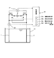
- FIG. 1 shows a basic configuration of a functional water generator according to a first embodiment of the present invention.
- the functional water generating apparatus includes a treatment tank 10 as an example of a container in which an aqueous solution is stored, an ion adsorption electrode 1 disposed in the treatment tank 10, and a treatment tank. 10, a counter electrode 2 disposed so as to face the ion adsorption electrode 1 with a gap, a DC power source E for applying a DC voltage between the ion adsorption electrode 1 and the counter electrode 2, and an aqueous solution in the treatment tank 10. And a conductivity meter 11 for detecting the conductivity.
- the DC power source E is a constant current source or a constant voltage source.
- the ion-adsorbing electrode 1 is made of a porous carbon material (for example, activated carbon), and the counter electrode 2 may be an electrode member that does not dissolve, and may be carbon or the like, but a metal that easily undergoes electrolysis of water (for example, Pt, At least one metal (or alloy) of Au, Pd, Rh, and Ir is suitable.
- a metal that easily undergoes electrolysis of water for example, Pt, At least one metal (or alloy) of Au, Pd, Rh, and Ir is suitable.
- the surface of an electrode made of Ti may be coated with Pt.
- the ion adsorption electrode 1 and the counter electrode 2 are formed in a flat plate shape, but may be appropriately set according to the electrode material and the shape of the container.
- the positive electrode side of the DC power supply E is connected to the ion adsorption electrode 1 and the counter electrode 2 via the changeover switch SW1
- the negative electrode side of the DC power supply E is connected to the ion adsorption electrode 1 via the changeover switch SW2. 2 is connected.
- the changeover switches SW1 and SW2 By switching the changeover switches SW1 and SW2, the ion adsorption electrode 1 and the counter electrode 2 are arranged so that the ion adsorption electrode 1 becomes an anode (or cathode) and the counter electrode 2 becomes a cathode (or anode). A voltage is applied between them.
- the DC power supply E and the changeover switches SW1 and SW2 constitute voltage application means.
- the functional water generating device includes a control device 20 including a microcomputer and an input / output circuit.
- the control device 20 performs functional water generation processing by controlling the changeover switches SW1 and SW2 based on the conductivity of the aqueous solution detected by the conductivity meter 11.
- control device 20 includes a change point determination unit 20a that determines a change point at which the conductivity of the aqueous solution changes nonlinearly after a linear change period in which the conductivity of the aqueous solution in the treatment tank 10 changes linearly, and the ion adsorption electrode 1
- a start point determination unit 20b is provided that determines a start point at which a linear change period in which the conductivity of the aqueous solution changes linearly after a voltage is applied between the counter electrode 2 and the counter electrode 2 is applied.
- the linear change period in which the conductivity changes linearly is a period in which the change rate of the conductivity (change per unit time) is substantially constant.
- the functional water generating apparatus capable of controlling the ion concentration in an aqueous solution to which the present invention is applied, forms ions in the aqueous solution by forming an electric double layer capacitor between the surface of the ion adsorption electrode 1 and the ions.
- ions corresponding to the amount of adsorbed ions are reduced from the aqueous solution.
- this functional water generating apparatus releases ions adsorbed on the ion adsorption electrode 1 into the aqueous solution by eliminating the formation of the electric double layer capacitor between the surface of the ion adsorption electrode 1 and the ions. It is possible to increase the amount of ions.
- the electric double layer capacitor when the electric double layer capacitor is formed, the electric charge at the time of forming the capacitor is generated by the polarization inside the ion adsorption electrode 1, but the reverse charge is also generated by this polarization. Since this reverse charge flows between the electrodes as a processing current, in this functional water generating apparatus, the installed electrodes are configured as a cathode electrode or an anode electrode. For this reason, one of these electrodes is composed of an electrode capable of adsorbing and desorbing ions. However, when ions are adsorbed and desorbed, it is necessary to reverse the polarity of the electrodes. Changes the polarity of the voltage applied between the electrodes. Table 1 shows the polarity of ions (positive ions and negative ions) and the state of the ion-adsorbing electrode 1 (cathode or anode) due to adsorption / desorption of ions.
- the ions adsorbed on the ion adsorption electrode 1 move between the electrodes according to the voltage applied between the electrodes, and form an electric double layer in the vicinity of the ion adsorption electrode 1. For this reason, when there are sufficient ions in the aqueous solution, there are many ions around the ion-adsorbing electrode 1, so that the electric double layer is efficiently formed. At this time, since the energy for forming the electric double layer is smaller than the electrolysis energy of water, the formation of the electric double layer is preferentially performed with respect to the treatment current.
- the amount of ions around the ion adsorption electrode 1 decreases, the amount of electric double layer formation also decreases. For this reason, the amount of current consumed in forming the electric double layer is reduced with respect to the amount of current flowing between the electrodes.
- the ion concentration in the aqueous solution is high, the ion adsorption / desorption treatment can be performed in a state where the treatment efficiency is still good even if the aqueous solution has been subjected to the ion adsorption / desorption treatment. Also, if the ion concentration in the aqueous solution is low, the treated aqueous solution cannot be treated as functional water with the specified ion concentration, so that the functional water generated by installing a pH meter will have the target ion concentration. Some have performed processing while detecting the ion concentration at the time of generating functional water by adjusting the voltage, current, or flow rate.
- An object of the present invention is not to measure the ion concentration of functional water that is finally required, but to provide a functional water generating device that performs ion adsorption / desorption treatment in a power efficient state.
- the conductivity is proportional to the amount of ions (however, the conductivity increases in any direction from pH 7), and the variation in conductivity depends on the ion mobility. The greater the amount, the greater the variation in conductivity.
- the amount of hydrogen ions increases / decreases for positive ions and the amount of hydroxide ions increases / decreases for negative ions according to the charge polarity and valence of the adsorbed / desorbed ions. To do.
- a capacitor is formed by charges corresponding to the bivalent amount corresponding to the charge amount of the positive ions due to polarization inside the ion adsorption electrode 1.
- the charge remaining at this time flows as a processing current.
- This processing current is generated by electrolysis of water at the counter electrode 2.
- oxygen (O 2 ) is generated on the counter electrode 2 side, hydroxide ions (OH ⁇ ) are consumed, but hydrogen ions (H + ) are generated.
- one hydroxide ion (OH ⁇ ) is consumed, one electron is generated, so that two hydrogen ions (H + ) are generated with respect to the treatment current for two valences.
- the amount of hydrogen ions (H + ) increases or decreases in the case of positive ions
- the amount of hydroxide ions (OH ⁇ ) increases or decreases in the case of negative ions, depending on the charge polarity and valence number of adsorbed and desorbed ions.
- the electrolysis reaction of water at the counter electrode 2 is different from that in the case of adsorption, but the amount of charge and the amount of generated hydrogen ions (H + ) or hydroxide ions (OH ⁇ ) are the same charge. Therefore, increase / decrease of hydrogen ions (H + ) or hydroxide ions (OH ⁇ ) occurs in the same manner. For this reason, pH and electrical conductivity have a correlation with the amount of adsorption / desorption charges to the ion adsorption electrode 1 of positive ions and negative ions.
- the amount of ions adsorbed and desorbed on the ion adsorption electrode 1 is proportional to the treatment current. For this reason, the amount of ions in the aqueous solution is uniformly increased or decreased according to the state of ion adsorption / desorption.
- the amount of ions in the aqueous solution or the amount of ions adsorbed on the ion adsorption electrode 1 is finite, when a certain amount of ion adsorption / desorption treatment is continuously performed, the ions necessary for the treatment are insufficient. It becomes the situation to do. In such a situation where ions are insufficient, the amount of ion adsorption / desorption decreases as in the tap water shown in FIG.
- Fig. 2 shows changes in the amount of adsorbed ions by tap water (black diamond ⁇ ) and saline (black square ⁇ ) with different ion concentrations.
- the horizontal axis represents the treatment time [minutes]
- the vertical axis represents the ions.
- the amount of adsorption [mol] is expressed.
- the processing conditions in FIG. 2 are as follows. Capacity of tap water: 80mL (hardness 50mg / L) Saline capacity: 80 mL (concentration 0.01 mol / L, salt dissolved in the above tap water) Constant current control: 90 mA, 18 mm distance between electrodes Activated carbon electrode: Activated carbon electrode sheet (manufactured by Kansai Thermal Chemical: MSP-20, weight content 92%, 50 ⁇ 50 ⁇ 0.45 mm)
- the salt solution has a sufficient amount of ions, so no change point appears, whereas the tap water is nonlinear after the ion adsorption amount changes linearly in a treatment time of 1 to 3 minutes. A changing point of change appears.
- ions that change the characteristics of water are other than hydrogen ions (H + ) and hydroxide ions (OH ⁇ ). This is because, in the adsorption / desorption of these hydrogen ions and hydroxide ions, the same ions are generated on the counter electrode 2 side, so that the change due to adsorption / desorption appears to be in an equilibrium state. For this reason, if the ion adsorption / desorption process proceeds to some extent, the composition ratio of hydrogen ions or hydroxide ions in the polarity ions gradually increases depending on the polarity of ions to be adsorbed / desorbed. It tends to decrease gradually. Compared to the change in conductivity when the amount of ions in the aqueous solution is consumed, the change rate of conductivity due to hydrogen ions and hydroxide ions is small, and this change makes the change point of conductivity invisible. There is no.
- the ion mobility of hydrogen ions (H + ) is much higher than that of other ions in the process of adsorbing positive ions. Since the adsorption of hydrogen ions is given priority, the adsorption of other positive ions is performed after the adsorption of hydrogen ions around the ion adsorption electrode 1 is performed to some extent. For this reason, a period in which the fluctuation of the conductivity is very small can be formed, so that the ion adsorption / desorption is efficiently performed by detecting the changing point where the conductivity changes nonlinearly except the period of the equilibrium state of the conductivity. Can be performed more accurately.
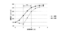
- FIGS. 3 and 4 The processing conditions of FIGS. 3 and 4 are as follows. Capacity of tap water: 80mL (hardness 50mg / L) Constant current control: 90 mA, 18 mm distance between electrodes Activated carbon electrode: Activated carbon electrode sheet (manufactured by Kansai Thermal Chemical: MSP-20, weight content 92%, 50 ⁇ 50 ⁇ 0.45 mm)
- the linear change period T1 of conductivity at the time of adsorption of positive ions indicated by a dotted line is between the processing time of 2 minutes and 4 minutes.
- the linear change period T2 of conductivity at the time of negative ion adsorption indicated by a solid line is between the processing time of 2 minutes and 5 minutes.
- an adsorption step in which ions in an aqueous solution are adsorbed to the ion adsorption electrode 1 by applying a voltage between the ion adsorption electrode 1 and the counter electrode 2 by the DC power source E.
- the change point determination unit 20a determines a change point at which the change rate of the conductivity of the aqueous solution changes, thereby detecting a decrease in ion adsorption / desorption efficiency.
- Ion adsorption / desorption can be efficiently processed according to the amount of ions adsorbed by the ion adsorption electrode.
- the change point determination unit 20a determines a change point at which the conductivity of the aqueous solution changes nonlinearly after a linear change period in which the conductivity of the aqueous solution changes linearly. It is possible to reliably detect a decrease in the adsorption / desorption efficiency.
- the DC power source E is a constant current source
- positive ions are applied to the ion adsorption electrode 1 after the voltage is applied between the ion adsorption electrode 1 and the counter electrode 2 until the conductivity of the aqueous solution changes linearly.
- the negative electrode is adsorbed and when negative ions are desorbed from the ion-adsorbing electrode 1, there is a period in which the variation in conductivity is very small. To do.
- the change point determination unit 20a does not determine the change point of the conductivity of the aqueous solution, thereby accurately determining the point where the conductivity of the aqueous solution changes from linear to nonlinear. Can be determined.
- the conductivity meter 11 for detecting conductivity is used, but a pH meter for detecting pH having a correlation with the conductivity may be used.
- the change in conductivity may be obtained based on the pH of the aqueous solution detected by the pH meter, and the change point at which the conductivity changes nonlinearly may be determined by the change point determination unit.
- the amount of ion adsorption adsorbed on the ion adsorption electrode 1 is proportional to the amount of treatment current.
- the term of water electrolysis current is such that oxygen (O 2 ) and hydrogen (H 2 ) are in the composition ratio of water at both electrodes. Since it is generated in proportion, it becomes a constant term that does not increase or decrease the ion concentration.
- the term of ion adsorption treatment current includes ion adsorption treatment current other than hydrogen ion (H + ) or hydroxide ion (OH ⁇ ) whose ion concentration varies due to ion adsorption, and hydrogen ion (H + ) or ion concentration that does not vary.
- FIG. 5 shows a basic configuration of a functional water generator of the second embodiment of the present invention.
- the functional water generator of the second embodiment includes a voltmeter and an ammeter instead of the conductivity meter. Except for the operation of the control device, the functional water generating device of the first embodiment has the same configuration, and the same components are denoted by the same reference numerals.
- the functional water generating apparatus includes a treatment tank 10 as an example of a container in which an aqueous solution is accommodated, an ion adsorption electrode 1 disposed in the treatment tank 10, and a treatment tank. 10, a counter electrode 2 disposed to face the ion adsorption electrode 1 with a space therebetween, a DC power source E that applies a DC voltage between the ion adsorption electrode 1 and the counter electrode 2, and an ion adsorption from the DC power source E
- a voltmeter 21 for detecting a voltage applied between the electrode 1 and the counter electrode 2 and an ammeter 22 for detecting a processing current flowing between the ion adsorption electrode 1 and the counter electrode 2 are provided.
- the DC power source E is a constant current source
- the ammeter 22 may not be provided
- the voltmeter 21 may not be provided.
- the positive electrode side of the DC power supply E is connected to the ion adsorption electrode 1 and the counter electrode 2 via the changeover switch SW1
- the negative electrode side of the DC power supply E is connected to the ion adsorption electrode 1 via the changeover switch SW2. 2 is connected.
- the changeover switches SW1 and SW2 By switching the changeover switches SW1 and SW2, the ion adsorption electrode 1 and the counter electrode 2 are arranged so that the ion adsorption electrode 1 becomes an anode (or cathode) and the counter electrode 2 becomes a cathode (or anode). A voltage is applied between them.
- the DC power supply E and the changeover switches SW1 and SW2 constitute voltage application means.
- the functional water generating device includes a control device 30 including a microcomputer and an input / output circuit.
- the control device 30 performs functional water generation processing by controlling the changeover switches SW1 and SW2 based on the output voltage of the DC power source E detected by the voltmeter 21 and the processing current detected by the ammeter 22.
- control device 30 includes a conductivity calculating unit 30a that calculates the conductivity of the aqueous solution based on the amount of current flowing between the ion adsorption electrode 1 and the counter electrode 2, and the conductivity of the aqueous solution in the treatment tank 10 is linear.
- the conductivity of the aqueous solution changes linearly after a voltage is applied between the change point determination unit 30b that determines a change point where the conductivity changes nonlinearly after the changing linear change period and the ion adsorption electrode 1 and the counter electrode 2. It has a start point determination unit 30c that determines a start point at which the linear change period starts, and an adsorption ion amount calculation unit 30d that calculates the amount of ions adsorbed on the ion adsorption electrode 1.
- the DC power source E As a constant current source, if there are enough ions in the aqueous solution, constant ion adsorption / desorption is performed for a constant processing current. At this time, the ion concentration in the aqueous solution fluctuates due to ion adsorption / desorption, so that the electric conductivity of the aqueous solution fluctuates. Therefore, the applied voltage from the DC power source E of the constant current source shows the same behavior as the fluctuation of the electric conductivity of the aqueous solution. It will be. For this reason, in the constant current control, it is possible to detect a change in conductivity based on a change in applied voltage.
- the conductivity of the aqueous solution By determining the change point at which the conductivity changes nonlinearly after the linear change period during which the ion changes linearly by the change point determination unit 30b, the ion adsorption / desorption ends when the ion adsorption / desorption efficiency starts to decrease, Thus, the current does not continue to flow between the electrodes in a state in which the adsorption / desorption efficiency of the electrode deteriorates, and the adsorption / desorption of ions can be efficiently processed.
- the conductivity of the aqueous solution has a correlation with the amount of charge / desorption to the ion adsorption electrode 1 of positive ions or negative ions, the voltage applied between the ion adsorption electrode 1 and the counter electrode 2 by the DC power source E. And based on the electric current which flows between the ion adsorption electrode 1 and the counter electrode 2, the electrical conductivity of aqueous solution can be easily calculated by the electrical conductivity calculation part 30a.
- start point determination unit 30c determines the start point of the linear change period in which the conductivity of the aqueous solution changes linearly, and determines the change point at which the conductivity of the aqueous solution changes nonlinearly between the voltage application and the start point. Is not performed by the change point determination unit 30b, the change point of the conductivity of the aqueous solution can be accurately determined.
- the change point determination part 30b is the voltage applied between the ion adsorption electrode 1 and the counter electrode 2.
- a change point at which the voltage changes nonlinearly after a linear change period in which the change is linear is taken as a change point of conductivity. Therefore, based on the voltage applied between the ion adsorption electrode 1 and the counter electrode 2, the change point when the electrical conductivity of the aqueous solution changes nonlinearly from the linear change period can be easily determined.
- the ion adsorption electrode 1 and the counter electrode 2 from the DC power source E.
- the amount of ions adsorbed on the ion adsorption electrode 1 can be accurately calculated by the adsorbed ion amount calculation unit 30d based on the amount of current flowing between the two.
- the DC power source E is a constant current source that outputs a constant current, a constant current flowing between the ion adsorption electrode 1 and the counter electrode 2 and an energization time (conductivity of the aqueous solution) by the adsorption ion amount calculation unit 30d.
- the amount of ions adsorbed on the ion-adsorbing electrode 1 can be calculated more accurately by obtaining the amount of processing current that is the product of the (linear change period).
- the ion adsorption electrode 1 by the direct current power source E is used.
- the amount of ions desorbed from the ion adsorption electrode 1 is accurately calculated by the adsorption ion amount calculation unit 30d based on the voltage applied between the ion adsorption electrode 1 and the counter electrode 2 and the current flowing between the ion adsorption electrode 1 and the counter electrode 2. can do.
- the amount of average current flowing between the ion adsorption electrode 1 and the counter electrode 2 and the energization time (conductivity of aqueous solution) are calculated by the adsorbed ion amount calculation unit 30d.
- the amount of ions adsorbed on the ion-adsorbing electrode 1 can be calculated more accurately by determining the amount of processing current that is the product of the linear rate change period).
- the conventional functional water generator has uniquely completed the adsorption / desorption treatment when the pH of the intended use is reached in an aqueous solution having a high ion concentration.
- the functional water generating apparatus according to the third embodiment of the present invention, if the processing efficiency can be continued in a state where the processing efficiency is high, the adsorption / desorption processing is continued within a range where high efficiency can be maintained. In this way, in the aqueous solution in which the adsorption / desorption treatment is continued, the amount of ions greatly fluctuates from the specification of the target functional water, so that it cannot be used directly as it is.
- the functional water generating apparatus of the third embodiment it is possible to adjust the target ion concentration by adding and diluting the untreated aqueous solution to the absorbed and desorbed aqueous solution.
- a mechanism is used that is mixed with an untreated aqueous solution.
- this functional water generating device does not have a mixing function part with the untreated aqueous solution inside, and only has a function of discharging to the flow path (or holding tank) of the untreated aqueous solution outside the device. You may have.
- the capacity when mixing the treated aqueous solution and the untreated aqueous solution is uniquely determined by the specifications of the target aqueous solution, it is necessary to have a device for managing the volume of the untreated aqueous solution.
- 1 ⁇ 10 ⁇ 7 mol / L of hydrogen ions (H + ) are present in 1 L (liter) of tap water at pH 7.
- 1 L functional water of pH 4 is finally desired, 1 L of functional water of pH 4 can be generated by generating acidic water of pH 3 in a 100 mL treatment tank 10 and mixing with 900 mL of untreated tap water. .
- Hydrogen ion concentration of pH 3 treated water 1 ⁇ 10 ⁇ 3 mol / L
- Hydrogen ion concentration of functional water at pH 4 1 ⁇ 10 ⁇ 4 mol / L
- Hydrogen ion concentration of tap water at pH 7 1 ⁇ 10 ⁇ 7 mol / L
- Hydrogen ion concentration of functional water at pH 4 ⁇ (1 ⁇ 10 ⁇ 3 mol / L ⁇ 100 mL / 1 L) + (1 ⁇ 10 ⁇ 7 mol / L ⁇ 900 mL / 1 L) ⁇ ⁇ 1L ⁇ 1 ⁇ 10 ⁇ 4 mol / L
- functional water having a target ion concentration can be generated. This can be similarly generated with respect to pH adjustment of alkaline water and hardness adjustment such as hard water and soft water if the ion concentration or the amount of ions per volume is determined.
- FIG. 6 is a block diagram showing a basic configuration of a functional water generation system using the functional water generation apparatus according to the third embodiment of the present invention.
- the functional water generating system of the present invention is a treatment tank 102 that performs adsorption / desorption of ions in an aqueous solution by the branch portion 101 of the untreated aqueous solution and the ion adsorption electrode 1 (shown in FIGS. 1 and 5).
- a mixing unit 103 for mixing the aqueous solution processed in the processing tank 102 and the unprocessed aqueous solution from the branching unit 101, and controlling the processing tank 102, the branching unit 101, the processing tank 102 and the mixing unit 103.
- the processing control unit 110 is configured.
- the untreated aqueous solution branch 101 flows the untreated aqueous solution through the treatment tank 102 and the mixing unit 103.
- the treatment tank 102 has the same configuration as that of any one of the functional water generators of the first and second embodiments.
- one of the electrodes of different polarities installed in the functional water generating device is the ion adsorption electrode 1, the other is the counter electrode 2, and the counter electrode 2 side is composed of a Pt electrode.
- each electrode does not need to have a single structure, and may be divided into a plurality of parts.
- each electrode is installed so that the whole is submerged in an aqueous solution (a solution obtained by dissolving an auxiliary in tap water or tap water, or a dedicated solution) placed in the treatment tank 102. There is no problem even if the entire electrode does not sink, but in this case, the adsorption / desorption area of the ion adsorption electrode 1 is reduced.
- the ion concentration differs for each local tap water, such as when using local tap water as an aqueous solution. Therefore, since the amount of ions contained in the aqueous solution varies from region to region, the treatment time that can be efficiently processed varies depending on the region. For this reason, functional water is generated by treating the aqueous solution in the treatment tank 102 in a treatment time according to the amount of ions in the region.
- the functional water generated in the treatment tank 102 has a variation in the amount of ions larger than the target ion control amount, an untreated aqueous solution is mixed in the mixing unit 103 so that the target ion amount is finally reached. To produce target functional water.
- the configuration diagram shown in FIG. 6 is a structure for keeping the specifications of the functional water when taken out, but in a system capable of performing processing in a state where it is stored in another tank at the time of use, the mixing unit 103
- the structure of the system can be simplified by adopting a structure that eliminates the problem or a structure that discharges the untreated aqueous solution through the treatment tank 102.
- the functional water generating apparatus of the present invention when the amount of the aqueous solution finally required is determined, there is no need to hold the aqueous solution in the treatment tank 102 more than necessary, so that the functional water generating apparatus is charged with ions.
- concentration measurement function it is possible to detect the amount of ions in the aqueous solution. If the amount of ions in the aqueous solution can be detected, the minimum required amount of aqueous solution can be calculated in reverse, so that it is not necessary to perform ion adsorption / desorption treatment on an excessive amount of aqueous solution.
- FIG. 7 is a block diagram which shows the basic composition of the functional water production
- the functional water generation system of the fourth embodiment has the same configuration as the functional water generation system of the third embodiment except for the drainage section 104. Moreover, it is set as the structure similar to the functional water production
- the ion concentration of the aqueous solution When the ion concentration of the aqueous solution is low, it works favorably for reducing the ion concentration of the aqueous solution, but even if trying to increase the amount of ions, it is not possible to adsorb more ions than the amount of ions in the aqueous solution, It is not possible to control ions by desorbing more than the adsorbed ions. However, even when the amount of ions that can be adsorbed from the aqueous solution in a single treatment is small, the amount of ions necessary for ion concentration control is adsorbed to the ion adsorption electrode 1 by treating the adsorption treatment multiple times while exchanging the aqueous solution be able to.
- an untreated aqueous solution is put into the treatment tank 102, and ion adsorption treatment in the aqueous solution is performed.
- An aqueous solution having a high ion concentration can adsorb more than the necessary amount of ions in one adsorption treatment, but if the ion concentration is low, the necessary amount of ions cannot be adsorbed only by this ion adsorption treatment.
- the treated aqueous solution is replaced with an untreated aqueous solution after draining, and ions are desorbed from the exchanged aqueous solution. Inability to produce water.
- the ion adsorption process is continuously performed without performing the ion desorption process, so that it is added to the previous ion adsorption amount and adsorbed on the ion adsorption electrode 1.
- the amount of ions to be increased can be increased.
- This ion adsorption treatment is performed a plurality of times until the necessary amount of ions is adsorbed.
- the ion adsorption process is terminated, and the treated aqueous solution is discharged from the treatment tank 102 via the drainage unit 104, and the treatment tank 102 is replaced with the untreated aqueous solution.
- the treated aqueous solution becomes functional water having a target specification.
- the flow channel is opened to the mixing unit 103, and when unnecessary, the flow channel is opened to the drainage unit 104. It is configured to open and discharge.
- the untreated aqueous solution for diluting the treated aqueous solution does not need to go through the functional water generating device unless it is required to have a constant specification at the outlet of the functional water generating device.
- the system can be miniaturized by calculating the ratio and providing a mixing amount control function outside.
- the change point at which the conductivity changes nonlinearly is detected, but the pH of the aqueous solution is detected using a pH meter, and the pH having a correlation with the conductivity is nonlinear. You may make it detect the changing point which changes.
- the functional water generation system of the said 3rd, 4th embodiment is a static water type, ion adsorption performance is good, and it is not necessary to have a processing tank more than a finally required capacity
- a processing current equal to or higher than the current that forms the electric double layer is passed, water electrolysis occurs, resulting in a decrease in power efficiency. . For this reason, there is a problem that the processing efficiency decreases when the processing current is increased in order to speed up the processing time, but since parallel processing can be performed in batch processing using a processing tank, it is possible to perform processing efficiently. Become.
- the change in conductivity correlates with the ion concentration of hydrogen ions and hydroxide ions.
- the amount of hydrogen ions for positive ions and the amount of hydroxide ions for negative ions increase / decrease according to the charge polarity and valence of the adsorbed / desorbed ions. For this reason, the conductivity has a correlation with the amount of charge / desorption charges to the ion adsorption electrode 1 of positive ions or negative ions.
- the treatment current flowing between the ion adsorption electrode 1 and the counter electrode 2 is made constant, the treatment current amount and the ion adsorption / desorption amount have a correlation, so that the ion adsorption amount is sufficient if ions are sufficiently present in the aqueous solution. Is constant, and if there are sufficient ions in the ion adsorption electrode 1, the ion desorption amount is constant.
- the amount of ion adsorption / desorption charge is calculated from the varying voltage with a constant processing current during the linear change period in which the change in conductivity is constant. Can be easily done.
- the variable value of the ion adsorption amount / input current amount is substantially constant. Since the variable value decreases as the value decreases, the efficiency of the ion adsorption / desorption state can be detected by monitoring the fluctuation of this value. Since there is a correlation between the ion adsorption amount and the conductivity, the adsorption efficiency can be monitored by monitoring the change in the conductivity.
- the change in conductivity is the same as the change in voltage applied between the ion adsorption electrode and the counter electrode, so the change in voltage is monitored. By doing so, it becomes possible to monitor the ion concentration.
- FIG. 8 shows a basic configuration of a functional water generator of the fifth embodiment of the present invention.
- the functional water generator of the fifth embodiment is the same as the functional water generator of the second embodiment except for the control device.
- the same configuration is given, and the same components are denoted by the same reference numerals.
- the functional water generating apparatus of the fifth embodiment includes a treatment tank 10 as an example of a container in which an aqueous solution is stored, an ion adsorption electrode 1 disposed in the treatment tank 10, and a treatment tank. 10, a counter electrode 2 disposed to face the ion adsorption electrode 1 with a space therebetween, a DC power source E that applies a DC voltage between the ion adsorption electrode 1 and the counter electrode 2, and an ion adsorption from the DC power source E
- a voltmeter 21 for detecting a voltage applied between the electrode 1 and the counter electrode 2 and an ammeter 22 for detecting a processing current flowing between the ion adsorption electrode 1 and the counter electrode 2 are provided.
- the DC power source E is a constant current source
- the ammeter 22 may not be provided
- the voltmeter 21 may not be provided.
- the positive electrode side of the DC power supply E is connected to the ion adsorption electrode 1 and the counter electrode 2 via the changeover switch SW1
- the negative electrode side of the DC power supply E is connected to the ion adsorption electrode 1 via the changeover switch SW2. 2 is connected.
- the changeover switches SW1 and SW2 By switching the changeover switches SW1 and SW2, the ion adsorption electrode 1 and the counter electrode 2 are arranged so that the ion adsorption electrode 1 becomes an anode (or cathode) and the counter electrode 2 becomes a cathode (or anode). A voltage is applied between them.
- the DC power supply E and the changeover switches SW1 and SW2 constitute voltage application means.
- the functional water generating device includes a control device 40 including a microcomputer and an input / output circuit.
- the control device 40 performs functional water generation processing by controlling the changeover switches SW1 and SW2 based on the output voltage of the DC power source E detected by the voltmeter 21 and the processing current detected by the ammeter 22.
- control device 40 includes a conductivity calculating unit 40a that calculates the conductivity of the aqueous solution based on the amount of current flowing between the ion adsorption electrode 1 and the counter electrode 2, and the conductivity of the aqueous solution in the treatment tank 10 is linear.
- the conductivity of the aqueous solution changes linearly after a voltage is applied between the change point determination unit 40b that determines a change point where the conductivity changes nonlinearly after the changing linear change period and the ion adsorption electrode 1 and the counter electrode 2.
- a start point determination unit 40c that determines a start point at which the linear change period starts, a time measurement unit 40d that measures the time from the application of the voltage to the start point, and a buffering action based on the time measured by the time measurement unit 40d
- a buffering ion amount calculating unit 40e for calculating an ion amount.
- the functional water generator of the fifth embodiment has the same effect as the functional water generator of the second embodiment.
- the functional water generator configured as described above also functions as an ion sensor that detects the amount of buffering ions such as bicarbonate ions (bicarbonate ions).
- buffering ions such as bicarbonate ions (bicarbonate ions).
- the ion sensor function for detecting the amount of buffer ions such as bicarbonate ions is the electrolysis of water at the counter electrode 2 when positive ions (or negative ions) in an aqueous solution are adsorbed to the ion adsorption electrode 1 according to the electric double layer theory. Chemical changes that generate hydrogen ions (or hydroxide ions) are used.
- the amount of hydrogen ion (or the amount of hydroxide ions) in the aqueous solution that is, the amount of change in the conductivity of the aqueous solution due to pH fluctuation is larger than the amount of change in the conductivity of the aqueous solution due to the adsorption of ions to the ion adsorption electrode 1.
- the point of change in the conductivity of the aqueous solution appears when the buffering ions are gone.
- bicarbonate ions HCO 3 ⁇
- H + generated at the counter electrode 2
- desorption of positive ions and adsorption of negative ions are not connected to OH ⁇ generated at the counter electrode 2, but bicarbonate ions are separated and buffered when negative ions are adsorbed to the ion adsorption electrode 1. An effect occurs.
- the functional water generating apparatus using the electric double layer of the fifth embodiment since an imbalance between hydrogen ions and hydroxide ions occurs in the same treatment tank 10, at least one of the treatment current or the treatment voltage is an aqueous solution. It will fluctuate due to the change in conductivity. By making the processing current (or processing voltage) constant, the other voltage (or current) is affected, so a change point (starting point where the linear change period begins) also appears in this voltage value (or current value). It will be.
- the time from the start point of the adsorption process or the desorption process (the point where voltage application is started) to the start point of the linear change period in which the conductivity of the aqueous solution changes linearly is measured by the time measuring unit 40d. Based on the measured time, the voltage applied between the ion adsorption electrode 1 and the counter electrode 2, and the current flowing between the ion adsorption electrode 1 and the counter electrode 2, the buffering ion amount is measured. It is calculated by the buffering ion amount calculation unit 40e. Thereby, it is possible to detect the amount of buffering ions with a simple configuration.
- the functional water generating apparatus using the electric double layer regardless of the flowing water type and the batch type system, it is not necessary to newly provide a sensing unit, and water is accumulated between the electrodes. In the first treatment, the amount of buffering ions such as bicarbonate ions contained in the water can be detected.
- the purpose is to detect the change point of the conductivity of the aqueous solution, so the electrode size is necessary for detection Since the minimum size is sufficient, it can be provided as a small sensor unit.
- the sensor components are simple, it is possible to provide an inexpensive ion sensor, and high-precision sensing without requiring special sensor calibration work or the like. Is possible.
- the functional water generating apparatus of the fifth embodiment forms ions in the aqueous solution by forming an electric double layer capacitor between the ions in the aqueous solution and the surface of the ion adsorption electrode 1, thereby allowing the ions to be adsorbed on the surface of the ion adsorption electrode 1. Decrease. Further, by eliminating the formation of the electric double layer capacitor between the surface of the ion adsorption electrode 1 and the ions, the ions adsorbed on the ion adsorption electrode 1 are desorbed in the aqueous solution to increase the amount of ions in the aqueous solution.
- the ion adsorption electrode 1 has a structure having one or a plurality of ion adsorption electrodes
- the counter electrode 2 is an electrode capable of electrolyzing platinum-based water.
- This functional water generating device has a structure having one or a plurality thereof, and functions as an ion sensor having a treatment tank 10 capable of holding an aqueous solution for sensing between the ion adsorption electrode 1 and the counter electrode 2. To do.
- hydrogen ions or hydroxide ions
- the amount of positive ions other than hydrogen ions or the amount of negative ions other than hydroxide ions in the aqueous solution will decrease, so that ion adsorption of hydrogen ions (or hydroxide ions) will occur and the ion state Is gradually approaching an equilibrium state, so the increase in conductivity gradually decreases and eventually changes little.
- the amount of hydrogen ions increases / decreases for positive ions and the amount of hydroxide ions increases / decreases for negative ions according to the polarity and valence of charges of adsorbed / desorbed ions.
- monovalent ions are adsorbed and desorbed at the ion adsorption electrode 1
- electrons are exchanged at the counter electrode 2 due to the polarity of the adsorbed ions, and the above equations (1), (1) ′, (2 ), (2) 'reaction occurs.
- the pH and conductivity correlate with the amount of charge / desorption charges of positive ions or negative ions to the ion adsorption electrode 1.
- buffer ions such as free carbonates that have a buffering effect on pH such as bicarbonate ions
- the content of the buffer ions varies depending on the region. It was impossible to perform the same electrolytic treatment depending on the treatment conditions.
- buffered ions will have a large effect on the pH of the alkaline water that is finally conditioned, so conventionally treated aqueous solutions are sensed with a pH sensor or conductivity sensor. By doing so, the quality of the aqueous solution was made constant.
- adsorption and desorption of ions in the aqueous solution are performed on the ion adsorption electrode 1 side.
- the supply and consumption of charges used in the adsorption and desorption of ions are counter electrodes.
- 2 is performed by electrolytic treatment of water.
- hydrogen ions (or hydroxide ions) generated at the same time can exist in the aqueous solution as they are unless there is an ion having a buffering effect, causing a change in pH of the aqueous solution.
- Ionic conductivity is Since there is a relationship of hydrogen ions> hydroxide ions >> other ions, the change in conductivity of the aqueous solution when hydrogen ions (or hydroxide ions) increase is greater than the decrease due to adsorption of ions in the aqueous solution Therefore, there is a change point of conductivity when there is a buffering action of pH and after the buffering action of pH disappears.
- the functional water generating apparatus having the configuration of the fifth embodiment is implemented as a single sensor that detects the amount of buffering ions such as bicarbonate ions, a minimum required aqueous solution is interposed between the ion adsorption electrode and the counter electrode. There is no need to increase the distance between the ion adsorption electrode and the counter electrode. When the distance between the ion-adsorbing electrode and the counter electrode is reduced, the electrical resistance of water between the electrodes is also reduced, the applied voltage can be lowered, and the power consumption is reduced.
- the distance between the ion adsorption electrode and the counter electrode is preferably about 2 mm to 15 mm.
- the processing time increases, but the number of voltage or current sampling data increases, so the detection accuracy improves.
- the processing time can be shortened by reducing the distance between the electrodes, so that it is possible to select an appropriate combination of values according to the processing time and the required accuracy.
- the ion sensor function for detecting the amount of buffering ions in the fifth embodiment is not limited to a functional water generator, but is applied to a water conditioner or a device affected by buffering ions (such as bicarbonate ions) in an aqueous solution. can do.
- the characteristics of the generated functional water vary depending on the concentration of bicarbonate ions having a buffering action contained in an aqueous solution such as tap water. For this reason, a sensor for bicarbonate ions has been devised in order to make the characteristics of the generated functional water constant by sensing the amount of ions having a buffering action such as bicarbonate ions in water.
- the functional water generating apparatus having the ion sensor function of the fifth embodiment can provide a low-cost ion sensor that can detect the amount of buffering ions such as bicarbonate ions with a simple configuration. .
- the functional water generator of this invention is A container 10 containing an aqueous solution; An ion-adsorbing electrode 1 disposed in the container 10 and capable of adsorbing and desorbing ions in the aqueous solution; A counter electrode 2 disposed in the container 10 so as to face the ion-adsorbing electrode 1 with a space therebetween; Voltage application means (E, SW1, SW2) for applying a voltage between the ion adsorption electrode 1 and the counter electrode 2; An adsorption step in which ions in the aqueous solution are adsorbed to the ion adsorption electrode 1 by applying a voltage between the ion adsorption electrode 1 and the counter electrode 2 by the voltage application means (E, SW1, SW2) or the ion
- the desorption step of desorbing ions from the adsorption electrode 1 into the aqueous solution includes change point determination units 20a, 30b, and 40b that determine change points at which the change rate of the conductivity of the aqueous
- the adsorption step (or the step of adsorbing ions in the aqueous solution to the ion adsorption electrode 1 by applying a voltage between the ion adsorption electrode 1 and the counter electrode 2 by the voltage application means (E, SW1, SW2) (or In the desorption step in which ions are desorbed from the ion adsorption electrode 1 into the aqueous solution), the change point determination unit 20a, 30b, or 40b determines the change point at which the change rate of the conductivity of the aqueous solution changes. A decrease in efficiency can be detected.
- Ion adsorption / desorption can be efficiently processed according to the amount of ions adsorbed by the ion adsorption electrode 1.
- the change point is a change point at which the conductivity of the aqueous solution changes nonlinearly after a linear change period in which the conductivity of the aqueous solution changes linearly.
- the change point determination unit 20a, 30b in the adsorption process (or desorption process), the change point determination unit 20a, 30b, the change point at which the conductivity of the aqueous solution changes nonlinearly after the linear change period in which the conductivity of the aqueous solution changes linearly.
- a conductivity calculating unit 30a that calculates the conductivity of the aqueous solution based on the voltage applied between the ion adsorption electrode 1 and the counter electrode 2 and the current flowing between the ion adsorption electrode 1 and the counter electrode 2.
- the change point determination unit 30b determines a change point at which the conductivity changes nonlinearly based on the conductivity of the aqueous solution calculated by the conductivity calculation units 30a and 40a.
- the voltage application means causes the ion adsorption electrode.
- the conductivity of the aqueous solution can be easily calculated by the conductivity calculators 30a and 40a. .
- Start point determination units 30c and 40c for determining a start point at which a linear change period in which the conductivity of the aqueous solution linearly changes after a voltage is applied between the ion adsorption electrode 1 and the counter electrode 2 are provided.
- the conductivity of the aqueous solution changes linearly after the voltage is applied between the ion adsorption electrode 1 and the counter electrode 2.
- the starting point determination unit 30c, 40c determines the starting point of the linear change period in which the conductivity of the aqueous solution changes linearly, and the voltage of the ion adsorbing electrode 1 and the counter electrode 2 is applied before the electric conductivity of the aqueous solution.
- the change point determination units 20a, 30b, and 40b By preventing the change point determination units 20a, 30b, and 40b from determining the change point of the conductivity of the aqueous solution until the linear change period in which the change of the linearity starts, the change point of the conductivity of the aqueous solution is accurately determined. Can be determined.
- the voltage applying means (E, SW1, SW2) is a constant current source
- the change point determination units 20a, 30b, and 40b determine a change point at which the voltage changes nonlinearly after a linear change period in which the voltage applied between the ion adsorption electrode 1 and the counter electrode 2 changes linearly. A change point where the conductivity changes nonlinearly.
- constant current control is performed so that a constant processing current flows between the ion adsorption electrode 1 and the counter electrode 2, so that a constant ion absorption with respect to the processing current can be obtained if sufficient ions exist in the aqueous solution. Since desorption is performed and the treatment current does not vary, the ion concentration in the aqueous solution varies due to ion adsorption / desorption, and the conductivity of the aqueous solution varies. Therefore, the voltage applied between the ion adsorption electrode 1 and the counter electrode 2 Shows the same behavior as the variation in conductivity.
- the change point determination units 20a, 30b, and 40b are applied between the ion adsorption electrode 1 and the counter electrode 2.
- the change point at which the voltage changes nonlinearly after the linear change period during which the applied voltage changes linearly is defined as the change point at which the conductivity of the aqueous solution changes nonlinearly. Therefore, based on the voltage applied between the ion adsorption electrode 1 and the counter electrode 2, the change point when the electrical conductivity of the aqueous solution changes nonlinearly from the linear change period can be easily determined.
- an adsorption ion amount calculation unit 30 d that calculates the amount of ions adsorbed to the ion adsorption electrode 1 from the aqueous solution is provided.
- the amount of ions adsorbed on the ion adsorbing electrode 1 is accurately calculated by the adsorbed ion amount calculating unit 30d. Can be calculated.
- a time measuring unit 40d for measuring the time from the start point of the adsorption step or the desorption step to the start point of a linear change period in which the conductivity of the aqueous solution changes linearly; Based on the voltage applied between the ion adsorption electrode 1 and the counter electrode 2, the current flowing between the ion adsorption electrode 1 and the counter electrode 2, and the time measured by the time measurement unit 40d And a buffering ion amount calculating unit 40e for calculating the amount of working ions.
- the time from the start point of the adsorption step or the desorption step to the start point of the linear change period in which the conductivity of the aqueous solution changes linearly is measured by the time measurement unit 40d, and the measurement is performed. Based on the time, the voltage applied between the ion adsorption electrode 1 and the counter electrode 2, and the current flowing between the ion adsorption electrode 1 and the counter electrode 2, the buffering ion amount is calculated by the buffering ion amount calculation unit 40e. Since it is calculated, the amount of buffering ions can be detected with a simple configuration.
Landscapes
- Life Sciences & Earth Sciences (AREA)
- General Life Sciences & Earth Sciences (AREA)
- Geology (AREA)
- Hydrology & Water Resources (AREA)
- Engineering & Computer Science (AREA)
- Environmental & Geological Engineering (AREA)
- Water Supply & Treatment (AREA)
- Chemical & Material Sciences (AREA)
- Organic Chemistry (AREA)
- Water Treatment By Electricity Or Magnetism (AREA)
Abstract
機能水生成装置は、電圧印加手段(E,SW1,SW2)によりイオン吸着電極(1)と対極(2)との間に電圧を印加することによりイオン吸着電極(1)に水溶液中のイオンを吸着させる吸着工程またはイオン吸着電極(1)から水溶液中にイオンを脱離させる脱離工程において、水溶液の導電率の変化率が変わる変化点を判定する変化点判定部(20a)を備える。これにより、イオンの吸脱着効率の低下を検知でき、水溶液中のイオン量やイオン吸着電極の吸着イオン量に応じてイオンの吸脱着を効率よく処理することが可能な機能水生成装置を提供する。
Description
この発明は、機能水生成装置に関し、詳しくは、イオン吸着電極を用いた機能水生成装置に関する。
従来、機能水生成装置としては、イオン透過性の隔膜を挟んで2つの電極を配置し、塩水を電気分解して酸性水とアルカリ性水とを調製するものがある(例えば、特許3291054号(特許文献1)参照)。この機能水生成装置は、電極間を流れる水を電気分解することによって、アルカリ性水の層流と酸性水の層流とを形成し、それらを別々に取り出すことによって、アルカリ性水および酸性水を得る。
ところが、上記従来の機能水生成装置は、pHメータを用いて正確な機能水の生成を行うものであって、機能水を効率よく生成するものではない。また、上記従来の機能水生成装置は、アノードにおける酸素ガスおよび水素イオン生成反応と、カソードにおける水素ガスおよび水酸イオン生成反応とが同時に行われるため、アノードおよびカソードの両方に、高価な白金等で覆われた電極が用いられていた。また、上記従来の機能水生成装置では、イオン透過性の隔膜を用いてpHが調整された水溶液の塩濃度が高くなって装置自体が腐食しやすいという問題がある。
そこで、電気二重層理論を用いたイオン吸着電極で水溶液中のイオンの吸脱着することによりpHなどの調整を行う機能水生成装置が提案されている。この機能水生成装置は、イオン吸着時に水溶液中のイオンが少なくなると、イオン吸着を効率よく処理できなくなったり、イオン脱離時にイオン吸着電極に吸着していたイオンが少なくなると、イオン脱離を効率よく処理できなくなったりするという問題がある。
そこで、この発明の課題は、イオンの吸脱着効率の低下を検知でき、水溶液中のイオン量やイオン吸着電極の吸着イオン量に応じてイオンの吸脱着を効率よく処理することが可能な機能水生成装置を提供することにある。
上記課題を解決するため、この発明の機能水生成装置は、
水溶液が収容される容器と、
上記容器内に配置され、上記水溶液中のイオンの吸着および脱離が可能なイオン吸着電極と、
上記容器内に上記イオン吸着電極と間隔をあけて対向するように配置された対極と、
上記イオン吸着電極と上記対極との間に電圧を印加する電圧印加手段と、
上記電圧印加手段により上記イオン吸着電極と上記対極との間に電圧を印加することにより上記イオン吸着電極に上記水溶液中のイオンを吸着させる吸着工程または上記イオン吸着電極から上記水溶液中にイオンを脱離させる脱離工程において、上記水溶液の導電率の変化率が変わる変化点を判定する変化点判定部と
を備えたことを特徴とする。
水溶液が収容される容器と、
上記容器内に配置され、上記水溶液中のイオンの吸着および脱離が可能なイオン吸着電極と、
上記容器内に上記イオン吸着電極と間隔をあけて対向するように配置された対極と、
上記イオン吸着電極と上記対極との間に電圧を印加する電圧印加手段と、
上記電圧印加手段により上記イオン吸着電極と上記対極との間に電圧を印加することにより上記イオン吸着電極に上記水溶液中のイオンを吸着させる吸着工程または上記イオン吸着電極から上記水溶液中にイオンを脱離させる脱離工程において、上記水溶液の導電率の変化率が変わる変化点を判定する変化点判定部と
を備えたことを特徴とする。
また、一実施形態の機能水生成装置では、
上記変化点は、上記水溶液の導電率が線形変化する線形変化期間の後に上記水溶液の導電率が非線形変化する変化点である。
上記変化点は、上記水溶液の導電率が線形変化する線形変化期間の後に上記水溶液の導電率が非線形変化する変化点である。
また、一実施形態の機能水生成装置では、
上記イオン吸着電極と上記対極との間に印加された電圧および上記イオン吸着電極と上記対極との間に流れる電流に基づいて、上記水溶液の導電率を算出する導電率算出部を備え、
上記変化点判定部は、上記導電率算出部により算出された上記水溶液の導電率に基づいて、上記導電率が非線形変化する変化点を判定する。
上記イオン吸着電極と上記対極との間に印加された電圧および上記イオン吸着電極と上記対極との間に流れる電流に基づいて、上記水溶液の導電率を算出する導電率算出部を備え、
上記変化点判定部は、上記導電率算出部により算出された上記水溶液の導電率に基づいて、上記導電率が非線形変化する変化点を判定する。
また、一実施形態の機能水生成装置では、
上記イオン吸着電極と上記対極との間に電圧が印加されてから上記水溶液の導電率が線形変化する線形変化期間が始まる開始点を判定する開始点判定部を備えた。
上記イオン吸着電極と上記対極との間に電圧が印加されてから上記水溶液の導電率が線形変化する線形変化期間が始まる開始点を判定する開始点判定部を備えた。
また、一実施形態の機能水生成装置では、
上記電圧印加手段が定電流源であって、
上記変化点判定部は、上記イオン吸着電極と上記対極との間に印加された電圧が線形変化する線形変化期間の後に上記電圧が非線形変化する変化点を上記水溶液の導電率が非線形変化する変化点とする。
上記電圧印加手段が定電流源であって、
上記変化点判定部は、上記イオン吸着電極と上記対極との間に印加された電圧が線形変化する線形変化期間の後に上記電圧が非線形変化する変化点を上記水溶液の導電率が非線形変化する変化点とする。
また、一実施形態の機能水生成装置では、
上記電圧印加手段により上記イオン吸着電極と上記対極との間に電圧を印加することにより上記イオン吸着電極に上記水溶液中のイオンを吸着させる吸着工程において、上記イオン吸着電極と上記対極との間に流れた電流量に基づいて、上記水溶液から上記イオン吸着電極に吸着したイオン量を算出する吸着イオン量算出部を備えた。
上記電圧印加手段により上記イオン吸着電極と上記対極との間に電圧を印加することにより上記イオン吸着電極に上記水溶液中のイオンを吸着させる吸着工程において、上記イオン吸着電極と上記対極との間に流れた電流量に基づいて、上記水溶液から上記イオン吸着電極に吸着したイオン量を算出する吸着イオン量算出部を備えた。
また、一実施形態の機能水生成装置では、
上記吸着工程または上記脱離工程の開始点から上記水溶液の導電率が線形変化する線形変化期間の開始点までの時間を計測する時間計測部と、
上記イオン吸着電極と上記対極との間に印加された電圧と上記イオン吸着電極と上記対極との間に流れる電流および上記時間計測部により計測された上記時間に基づいて、緩衝作用イオン量を算出する緩衝作用イオン量算出部と
を備えた。
上記吸着工程または上記脱離工程の開始点から上記水溶液の導電率が線形変化する線形変化期間の開始点までの時間を計測する時間計測部と、
上記イオン吸着電極と上記対極との間に印加された電圧と上記イオン吸着電極と上記対極との間に流れる電流および上記時間計測部により計測された上記時間に基づいて、緩衝作用イオン量を算出する緩衝作用イオン量算出部と
を備えた。
以上より明らかなように、この発明によれば、電圧印加手段によりイオン吸着電極と対極との間に電圧を印加してイオン吸着電極に水溶液中のイオンを吸着させる吸着工程(またはイオン吸着電極から水溶液中にイオンを脱離させる脱離工程)において、変化点判定部により、水溶液の導電率が線形変化する線形変化期間の後に導電率が非線形変化する変化点を判定することによって、イオンの吸脱着効率の低下を検知でき、水溶液中のイオン量やイオン吸着電極の吸着イオン量に応じてイオンの吸脱着を効率よく処理することができる機能水生成装置を実現することができる。
以下、この発明の機能水生成装置を図示の実施の形態により詳細に説明する。
〔第1実施形態〕
図1はこの発明の第1実施形態の機能水生成装置の基本構成を示している。
図1はこの発明の第1実施形態の機能水生成装置の基本構成を示している。
この第1実施形態の機能水生成装置は、図1に示すように、水溶液が収容される容器の一例としての処理槽10と、処理槽10内に配置されたイオン吸着電極1と、処理槽10内にイオン吸着電極1と間隔をあけて対向するように配置された対極2と、イオン吸着電極1と対極2との間に直流電圧を印加する直流電源Eと、処理槽10内の水溶液の導電率を検出する導電率計11とを備えている。ここで、直流電源Eは、定電流源または定電圧源とする。
上記イオン吸着電極1は、多孔質の炭素材料(例えば活性炭)からなり、対極2は、溶解しない電極部材であればよく、カーボンなどでもよいが、水の電気分解が生じやすい金属(例えばPt,Au,Pd,Rh,Irの少なくとも1つの金属(または合金))が好適であり、例えばTiからなる電極の表面をPtで被覆したものでもよい。また、この実施の形態では、イオン吸着電極1および対極2は平板状としているが、電極材料や容器の形状に応じて適宜設定すればよい。
また、上記機能水生成装置は、直流電源Eの正極側が切替スイッチSW1を介してイオン吸着電極1と対極2に接続され、直流電源Eの負極側が切替スイッチSW2を介してイオン吸着電極1と対極2に接続されている。上記切替スイッチSW1,SW2を切り替えることにより、イオン吸着電極1が陽極(または陰極)になるように、かつ、対極2が陰極(または陽極)になるように、イオン吸着電極1と対極2との間に電圧を印加する。上記直流電源Eと切替スイッチSW1,SW2で電圧印加手段を構成している。
また、上記機能水生成装置は、マイクロコンピュータと入出力回路などからなる制御装置20を備えている。この制御装置20は、導電率計11により検出された水溶液の導電率に基づいて、切替スイッチSW1,SW2を制御することにより機能水生成処理を行う。
また、制御装置20は、処理槽10内の水溶液の導電率が線形変化する線形変化期間の後に水溶液の導電率が非線形変化する変化点を判定する変化点判定部20aと、イオン吸着電極1と対極2との間に電圧が印加されてから水溶液の導電率が線形変化する線形変化期間が始まる開始点を判定する開始点判定部20bを有する。ここで、導電率が線形変化する線形変化期間とは、導電率の変化率(単位時間あたりの変化)がほぼ一定である期間のことである。
この発明が適用される水溶液中のイオン濃度を制御可能な機能水生成装置は、水溶液中のイオンをイオン吸着電極1の表面とイオンとの間で電気二重層キャパシタを形成することにより、イオンをイオン吸着電極1の表面に吸着させることで、吸着させたイオン量に相当するイオンを水溶液中から減少させる。また、この機能水生成装置は、イオン吸着電極1の表面とイオンとの電気二重層キャパシタの形成を解消させることにより、イオン吸着電極1に吸着したイオンを水溶液中に放出して、水溶液中のイオン量を増加させることが可能である。
この機能水生成装置では、電気二重層キャパシタの形成時にイオン吸着電極1の内部では分極により、キャパシタ形成時の電荷が作られるが、この分極では逆電荷も生成される。この逆電荷は、処理電流として電極間に流れるために、この機能水生成装置では、設置されている電極は、カソード電極やアノード電極として構成されることになる。このため、これらの電極の一方がイオンの吸脱着が可能な電極で構成されることになるが、イオンの吸脱着を行う場合には、電極の極性反転を行う必要があり、対象とするイオンによって電極間に印加する電圧の極性が変化する。イオンの極性(プラスイオン、マイナスイオン)とイオンの吸脱着によるイオン吸着電極1の状態(カソードまたはアノード)を次の表1に示す。

上記表1に示すように、イオンの吸着時と脱着時においてイオン吸着電極1の極性が反転する必要がある。また、処理するイオンの電荷によって同じ吸着処理であってもイオン吸着電極1の極性は反転することになる。このため、どちらの電極をカソードにするかは、処理する内容やイオンの電荷により選択すると共に、印加する処理電圧を最適に選択する回路(SW1,SW2を含む)が必要である。
イオン吸着電極1に吸着されるイオンは、電極間に印加された電圧に応じて電極間を移動し、イオン吸着電極1近傍にて電気二重層を形成する。このため、水溶液中にイオンが十分存在する場合は、イオン吸着電極1の周辺にイオンが多く存在するため、電気二重層の形成が効率よく行われる。このとき、電気二重層を形成するエネルギーが、水の電気分解エネルギーより小さいために、処理電流に対しては電気二重層の形成が優先的に行われる。
イオン吸着電極1の周辺のイオン量が減少してくると、電気二重層の形成量も減少する。このため、電極間に流れる電流量に対して電気二重層の形成で消費される電流量が減少する。
このような電流量に対して電気二重層の形成で消費される電極間に一定の電流を流す定電流制御では、その減少分の電流量は水の電気分解で消費されるためにイオン吸着効率は低下する。また、電極間に一定の電圧を印加する定電圧制御でも、イオン吸着によるpH変化に比例して、水溶液の導電率が変化するために、水溶液全体の処理電流が増加することも相まって、イオン吸着効率が減少する。このため、電力効率のよい処理時間は、水溶液中のイオン濃度により異なることになる。
従来の機能水生成装置においては、生成する機能水のpH値等の仕様を一定に合わせるために、未処理の水溶液において一定以上のイオン濃度であれば、中性からのpH等の変動量は、イオン吸着量とは相関しているために処理電圧または処理電流を一定にするように、定電圧制御または定電流制御にて処理している。
このため、水溶液中のイオン濃度が高ければ、イオン吸脱着処理を終了した水溶液であっても、まだ処理効率の良い状態でイオン吸脱着処理を行うことが可能であった。また、水溶液中のイオン濃度が低ければ、処理後の水溶液は指定したイオン濃度の機能水として処理することができないため、pHメータを設置して生成した機能水が目的のイオン濃度になるように電圧または電流や流量を調整することにより、機能水生成時のイオン濃度を検出しつつ処理を行うものもあった。
この発明の目的は、最終的に必要な機能水のイオン濃度を測定することが目的ではなく、電力効率のよい状態でイオン吸脱着処理を行う機能水生成装置を提供することである。
機能水の生成において、pHおよび導電率の変化は水素イオンおよび水酸化イオンのイオン濃度と相関関係があり、中性から水素イオン濃度が高くなる(水酸化イオン濃度が低くなる)とpHは減少し、導電率は増加する一方、中性から水酸化イオン濃度が高くなる(水素イオン濃度が低くなる)とpHと導電率は増加する。
ここで、導電率はイオン量に比例し(但しpH7からの何れの方向に対しても導電率は増加)、この導電率の変動はイオン移動度に依存するため、水素イオンや水酸化イオンの量が多くなるほど導電率の変動は大きくなる。
また、電気二重層を用いたイオン吸脱着では、吸脱着したイオンの電荷の極性および電価数に応じて、プラスイオンなら水素イオンの量が増減し、マイナスイオンなら水酸化イオンの量が増減する。
イオン吸着電極1にて1価のイオンが吸脱着した場合には、対極2では吸着したイオンの極性による電子のやり取りが発生し、以下のいずれかの反応が起こる。
プラスイオンがイオン吸着電極1に吸着した場合の対極2では、
OH- → 1/2 H2O + 1/4 O2 + e- …… (1)
1/2 H2O → H+ + 1/4 O2 + e- …… (1)’
となり、マイナスイオンがイオン吸着電極1に吸着した場合の対極2では、
H+ + e- → 1/2 H2 …… (2)
1/2 H2O + e- → 1/2 H2 + OH- …… (2)’
となる。
OH- → 1/2 H2O + 1/4 O2 + e- …… (1)
1/2 H2O → H+ + 1/4 O2 + e- …… (1)’
となり、マイナスイオンがイオン吸着電極1に吸着した場合の対極2では、
H+ + e- → 1/2 H2 …… (2)
1/2 H2O + e- → 1/2 H2 + OH- …… (2)’
となる。
例えば、2価のプラスイオンがイオン吸着電極1に吸着した場合には、イオン吸着電極1内部の分極によりプラスイオンの電荷量に相当する2価分の電荷によりキャパシタを形成する。このときに残った電荷は、処理電流として流れる。この処理電流は、対極2の水の電気分解にて生成される。この時には、対極2側において酸素(O2)が発生するために水酸化イオン(OH-)が消費されるが、水素イオン(H+)が生成される。水酸化イオン(OH-)が1個消費する時には、電子が1個生成されるため、2価分の処理電流に対して2個の水素イオン(H+)が生成されることになる。
一方、マイナスイオンの場合は、対極2側において、水素イオン(H+)が消費され、水酸化イオン(OH-)が生成されることとなり、水素イオン(H+)が1個消費される時には電子が1個必要となるために、処理電流の電荷量に応じて水酸化イオン(OH-)が生成される。
このために、吸脱着したイオンの電荷の極性および電価数に応じて、プラスイオンなら水素イオン(H+)が、マイナスイオンなら水酸化イオン(OH-)の量が増減する。イオン脱着の場合にも、対極2での水の電気分解の反応は吸着の場合と異なるが、電荷量と生成される水素イオン(H+)または水酸化イオン(OH-)の量は同電荷量となるので、同じように水素イオン(H+)または水酸化イオン(OH-)の増減が発生することになる。このため、pHおよび導電率は、プラスイオンやマイナスイオンのイオン吸着電極1への吸脱着電荷量と相関関係があることになる。
ここで、処理する水溶液中に十分なイオンが存在する場合は、イオン吸着電極1に吸脱着するイオンの量は、処理電流に比例する。このため、イオンの吸脱着の状況に応じて水溶液中のイオン量は一様な増減が行われることになる。ただし、水溶液中のイオン量またはイオン吸着電極1に吸着しているイオン量は有限であるために、一定量のイオン吸脱着処理を継続して行った場合には、処理に必要なイオンが不足する状況になる。このようなイオンが不足した状況では、図2に示す水道水のように、イオン吸脱着量も減少するために導電率の変化点が現れることになる。
図2はイオン濃度が異なる水道水(黒菱形◆)と食塩水(黒四角■)によるイオン吸着量の変化を示しており、図2において、横軸は処理時間[分]、縦軸はイオン吸着量[mol]を表す。
また、図2における処理条件は次のとおりである。
水道水の容量 : 80mL(硬度50mg/L)
食塩水の容量 : 80mL(濃度0.01mol/L、上記水道水に食塩を溶かしたもの)
定電流制御 : 90mA、電極間距離18mm
活性炭電極 : 活性炭電極シート(関西熱化学製:MSP-20、重量含有率92%、50×50×0.45mm)
水道水の容量 : 80mL(硬度50mg/L)
食塩水の容量 : 80mL(濃度0.01mol/L、上記水道水に食塩を溶かしたもの)
定電流制御 : 90mA、電極間距離18mm
活性炭電極 : 活性炭電極シート(関西熱化学製:MSP-20、重量含有率92%、50×50×0.45mm)
図2において、食塩水は、イオン量が十分にあるので、変化点は現れていないのに対して、水道水は、処理時間が1~3分の期間でイオン吸着量が線形変化した後に非線形変化する変化点が現れている。
このため、このイオン吸着量の変化点を検出することにより、水溶液中のイオンの吸脱着処理が効率良く行われているか否かを判別することが可能となる。
実際のイオンの吸脱着時においては、水の特性を変化させるイオンは、水素イオン(H+)および水酸化イオン(OH-)以外となる。なぜならば、これら水素イオンと水酸化イオンの吸脱着では、対極2側で同じイオンの発生が起こるために、吸脱着による変化は、見掛け上、平衡状態になるためである。このため、ある程度イオンの吸脱着処理が進むと、吸脱着されるイオンの極性によって、水素イオンまたは水酸化イオンのその極性のイオンにおける構成比が徐々に増加するために、イオンの吸脱着効率は徐々に低下する傾向となる。水溶液中のイオン量を消費した場合の導電率の変化と比較すると、水素イオンと水酸化イオンに起因する導電率の変化率が小さいために、こちらの変化により導電率の変化点が見えなくなることはない。
また、水溶液中のイオンの吸脱着処理で、プラスイオンを吸着させる処理では、水素イオン(H+)のイオン移動度が他のイオンと比較して非常に大きいために、他のプラスイオン吸着よりも水素イオンの吸着が優先されるために、イオン吸着電極1周辺の水素イオンの吸着がある程度行われてから他のプラスイオンの吸着が行われる。このため、導電率の変動が非常に小さい期間ができるので、この導電率の平衡状態の期間を除いて導電率が非線形変化する変化点を検出することにより、イオン吸脱着が効率よく行われているかをより精度よく行うことができる。この平衡期間が存在するのは、図3に示すプラスイオンの吸着時と、図4に示すマイナスイオンの脱着時であるため、この場合には、導電率が非線形変化する変化点の判定において上記平衡期間を除く必要がある。
また、上記以外に導電率が非線形変化する要因としては、水溶液中に含まれる炭酸イオンによる緩衝作用および溶液中に含まれる塩化物イオンによる影響も考えられる。炭酸イオンによる緩衝作用の場合においては、水素イオンと炭酸イオンとの結合により水中のイオンが減少する方向であるため、イオンの増加による導電率の増加減少は派生しないので、導電率が非線形変化する原因となる。また、水溶液中の塩化物イオンは、水酸化イオンよりイオン化傾向が小さいため、水溶液の電気分解を行った場合に水酸化イオンより先に塩素ガスを発生させる。塩素ガスは、溶液に溶存するとpHにより次亜塩素酸と塩酸に分離するが、この場合も、緩衝作用により大きくpHの変化が起きないため、水溶液中のイオンの増加の割合も水酸化イオンが電気分解した場合に比べて小さく、導電率の変動も小さくなるので、同様に導電率が非線形変化する原因となる。
図3,図4の処理条件は次のとおりである。
水道水の容量 : 80mL(硬度50mg/L)
定電流制御 : 90mA、電極間距離18mm
活性炭電極 : 活性炭電極シート(関西熱化学製:MSP-20、重量含有率92%、50×50×0.45mm)
水道水の容量 : 80mL(硬度50mg/L)
定電流制御 : 90mA、電極間距離18mm
活性炭電極 : 活性炭電極シート(関西熱化学製:MSP-20、重量含有率92%、50×50×0.45mm)
図3において、点線で示すプラスイオンの吸着時の導電率の線形変化期間T1は、処理時間2分~4分の間である。また、図4において、実線で示すマイナスイオンの吸着時の導電率の線形変化期間T2は、処理時間2分~5分の間である。
上記構成の機能水生成装置によれば、直流電源Eによりイオン吸着電極1と対極2との間に電圧を印加することによりイオン吸着電極1に水溶液中のイオンを吸着させる吸着工程(またはイオン吸着電極1から水溶液中にイオンを脱離させる脱離工程)において、水溶液の導電率の変化率が変わる変化点を変化点判定部20aにより判定することによって、イオンの吸脱着効率の低下を検知できる。したがって、イオンの吸脱着効率が低下し始めたらイオンの吸脱着を終了することで、イオンの吸脱着効率が悪くなった状態で電極間に電流を流し続けることがなくなり、水溶液中のイオン量やイオン吸着電極の吸着イオン量に応じてイオンの吸脱着を効率よく処理することができる。
また、上記吸着工程(または脱離工程)において、水溶液の導電率が線形変化する線形変化期間の後に上記水溶液の導電率が非線形変化する変化点を変化点判定部20aにより判定することによって、イオンの吸脱着効率の低下を確実に検知できる。
また、直流電源Eが定電流源であるときにイオン吸着電極1と対極2との間に電圧が印加されてから水溶液の導電率が線形変化するまでの間、イオン吸着電極1へのプラスイオンの吸着時とイオン吸着電極1からのマイナスイオンの脱着時に導電率の変動が非常に小さい期間ができ、開始点判定部20bによりこの水溶液の導電率が線形変化する線形変化期間の開始点を判定する。この電圧印加から線形変化期間の開始点までの期間は、変化点判定部20aが水溶液の導電率の変化点の判定を行わないことによって、水溶液の導電率が線形から非線形に変化する点を正確に判定することできる。
上記第1実施形態では、導電率を検出する導電率計11を用いたが、導電率と相関を有するpHを検出するpHメータを用いてもよい。この場合、pHメータにより検出された水溶液のpHに基づいて導電率の変化を求めて、変化点判定部により導電率が非線形変化する変化点を判定してもよい。
また、イオンの吸脱着を行うイオン極性の違いにより、時系列での導電率の変化の推移が異なるため、処理するイオンにより判定方法を最適化して精度の良いイオンの吸脱着処理を行うことができる。
特に、電圧印加手段で定電流制御を行った場合には、導電率計を設けることなく、印加電圧により導電率を同定することが可能となるため、定電圧制御の場合に必要な演算処理を行う必要が無くなる。
さらに、通常では水溶液中のイオン量以上を吸着できないが、イオン吸着電極に複数回連続して吸着させれば、水溶液中にあるイオン量以上のイオンを吸着させることができる。ただし、水溶液中のイオン量は場所によって一定ではないので、最適な印加電圧の制御は決めることができないため、最適な吸着条件で複数回の吸着を行うことが可能となる。また、イオン吸着電極へのイオン吸着処理が単独でも処理条件の最適化や、水溶液中から効率よくイオンを除去するという処理が容易に実現可能になる。
〔第2実施形態〕
次に、この発明の第2実施形態の機能水生成装置について説明する。上記第1実施形態の機能水生成装置では、導電率計を用いて導電率が非線形変化する変化点を判断したが、この第2実施形態の機能水生成装置では、導電率計を用いずに導電率が非線形変化する変化点を検出する。
次に、この発明の第2実施形態の機能水生成装置について説明する。上記第1実施形態の機能水生成装置では、導電率計を用いて導電率が非線形変化する変化点を判断したが、この第2実施形態の機能水生成装置では、導電率計を用いずに導電率が非線形変化する変化点を検出する。
処理する水溶液中に十分イオンが存在する場合は、イオン吸着電極1に吸着するイオン吸着量は処理電流量に比例する。ただし、処理電流量がイオン吸着量を超えた値に設定された場合には、イオン吸着のみでは処理電流量を確保することができないために、イオン吸着電極1の表面で水の電気分解反応が起こることにより、不足分の電子の生成や電子の消費が行われ、処理電流の不足分が生成されることになる。このため、処理電流とイオン吸着量は以下の関係となる。
(イオン吸着処理電流)+(水の電気分解電流) = 処理電流 …… (3)
(イオン吸着処理電流)+(水の電気分解電流) = 処理電流 …… (3)
上記式(3)の関係において、水溶液中のイオン濃度が十分高い場合は、水の電気分解電流の項は、両電極にて酸素(O2)および水素(H2)が水の構成比に比例して生成されるために、イオン濃度の増減は発生しない定数項となる。イオン吸着処理電流の項は、イオン吸着によりイオン濃度が変動する水素イオン(H+)もしくは水酸化イオン(OH-)以外のイオン吸着処理電流と、イオン濃度が変動しない水素イオン(H+)もしくは水酸化イオン(OH-)によるイオン吸着処理電流から構成されるため、上記式(3)は次の式(4)となる。
(イオン濃度変動に関与するイオン吸着処理電流)
+(イオン濃度変動に関与しないイオン吸着処理電流)
+(水の電気分解電流) = 処理電流 …… (4)
(イオン濃度変動に関与するイオン吸着処理電流)
+(イオン濃度変動に関与しないイオン吸着処理電流)
+(水の電気分解電流) = 処理電流 …… (4)
上記式(4)のうちイオン濃度の変動に関与しない項は、定数項と仮定できるため、この式(4)は次の式(5)に同定できる。
イオン濃度変動に関与するイオン吸着処理電流 = 処理電流の変動 …… (5)
イオン濃度変動に関与するイオン吸着処理電流 = 処理電流の変動 …… (5)
このため、イオン濃度変動は、処理電流量の変動として検出可能となる。また、イオン濃度が変動することにより、水溶液の導電率も変動することとなる。この変化の割合は一定であるために、水溶液の導電率と処理電流から求まる処理電圧の変動でもイオン濃度の変動を検出することが可能となる。
次に、直流電源Eを定電流源とした場合について説明する。
図5はこの発明の第2実施形態の機能水生成装置の基本構成を示しており、この第2実施形態の機能水生成装置は、導電率計の代わりに電圧計,電流計を備えた点と制御装置の動作を除いて第1実施形態の機能水生成装置と同一の構成をしており、同一構成部は同一参照番号を付している。
この第1実施形態の機能水生成装置は、図5に示すように、水溶液が収容される容器の一例としての処理槽10と、処理槽10内に配置されたイオン吸着電極1と、処理槽10内にイオン吸着電極1と間隔をあけて対向するように配置された対極2と、イオン吸着電極1と対極2との間に直流電圧を印加する直流電源Eと、直流電源Eからイオン吸着電極1と対極2との間に印加される電圧を検出する電圧計21と、イオン吸着電極1と対極2との間に流れる処理電流を検出する電流計22とを備えている。ここで、直流電源Eが定電流源である場合は、電流計22は無くてもよく、また、直流電源Eが定電圧源である場合は、電圧計21は無くてもよい。
また、上記機能水生成装置は、直流電源Eの正極側が切替スイッチSW1を介してイオン吸着電極1と対極2に接続され、直流電源Eの負極側が切替スイッチSW2を介してイオン吸着電極1と対極2に接続されている。上記切替スイッチSW1,SW2を切り替えることにより、イオン吸着電極1が陽極(または陰極)になるように、かつ、対極2が陰極(または陽極)になるように、イオン吸着電極1と対極2との間に電圧を印加する。上記直流電源Eと切替スイッチSW1,SW2で電圧印加手段を構成している。
また、上記機能水生成装置は、マイクロコンピュータと入出力回路などからなる制御装置30を備えている。この制御装置30は、電圧計21により検出された直流電源Eの出力電圧および電流計22により検出された処理電流に基づいて、切替スイッチSW1,SW2を制御することにより機能水生成処理を行う。
また、制御装置30は、イオン吸着電極1と対極2との間に流れた電流量に基づいて水溶液の導電率を算出する導電率算出部30aと、処理槽10内の水溶液の導電率が線形変化する線形変化期間の後に導電率が非線形変化する変化点を判定する変化点判定部30bと、イオン吸着電極1と対極2との間に電圧が印加されてから水溶液の導電率が線形変化する線形変化期間が始まる開始点を判定する開始点判定部30cと、イオン吸着電極1に吸着したイオン量を算出する吸着イオン量算出部30dとを有する。
直流電源Eを定電流源とすることにより、水溶液中にイオンが十分存在すれば、一定の処理電流に対して一定のイオン吸脱着が行われる。このとき、イオン吸脱着により水溶液中のイオン濃度は変動することにより、水溶液の導電率が変動するので、定電流源の直流電源Eからの印加電圧が水溶液の導電率の変動と同じ挙動を示すことになる。このため、定電流制御では、印加電圧の変動に基づいて導電率の変動を検出することが可能となる。
上記構成の機能水生成装置によれば、イオン吸着電極1に水溶液中のイオンを吸着させる吸着工程(またはイオン吸着電極1から水溶液中にイオンを脱離させる脱離工程)において、水溶液の導電率が線形変化する線形変化期間の後に導電率が非線形変化する変化点を変化点判定部30bにより判定することによって、イオンの吸脱着効率が低下し始めたらイオンの吸脱着を終了することで、イオンの吸脱着効率が悪くなった状態で電極間に電流を流し続けることがなくなり、イオンの吸脱着を効率よく処理することができる。
また、水溶液の導電率は、プラスイオンまたはマイナスイオンのイオン吸着電極1への吸脱着電荷量と相関関係を有するので、直流電源Eによりイオン吸着電極1と対極2との間に印加された電圧およびイオン吸着電極1と対極2との間に流れる電流に基づいて、導電率算出部30aにより水溶液の導電率を容易に算出することができる。
また、開始点判定部30cによりこの水溶液の導電率が線形変化する線形変化期間の開始点を判定して、電圧印加から開始点までの間は、水溶液の導電率が非線形変化する変化点の判定を変化点判定部30bが行わないことによって、水溶液の導電率の変化点を正確に判定することできる。
また、上記イオン吸着電極1と対極2との間に一定の処理電流を流す定電流制御とすることにより、水溶液中にイオンが十分存在すれば処理電流に対して一定のイオン吸脱着が行われ、処理電流が変動することなく、イオン吸脱着により水溶液中のイオン濃度は変動して水溶液の導電率が変動するので、イオン吸着電極1と対極2との間に印加された電圧が導電率の変動と同じ挙動を示す。これにより、定電流制御では、印加電圧の変動に基づいて導電率の変動を検出することが可能となり、変化点判定部30bは、イオン吸着電極1と対極2との間に印加された電圧が線形変化する線形変化期間の後に電圧が非線形変化する変化点を導電率の変化点とする。したがって、イオン吸着電極1と対極2との間に印加された電圧に基づいて、水溶液の導電率が線形変化期間から非線形変化するときの変化点を容易に判定することができる。
また、直流電源Eによりイオン吸着電極1と対極2との間に電圧を印加することによりイオン吸着電極1に水溶液中のイオンを吸着させる吸着工程において、直流電源Eからイオン吸着電極1と対極2との間に流れた電流量に基づいて、イオン吸着電極1に吸着したイオン量を吸着イオン量算出部30dで正確に算出することができる。
ここで、直流電源Eが一定電流を出力する定電流源であるので、吸着イオン量算出部30dによって、イオン吸着電極1と対極2との間に流す一定電流と通電時間(水溶液の導電率の線形変化期間)との積である処理電流量を求めることにより、イオン吸着電極1に吸着したイオン量をより正確に算出することができる。
同様に、直流電源Eによりイオン吸着電極1と対極2との間に電圧を印加することによりイオン吸着電極1から水溶液中にイオンを脱離させる脱離工程において、直流電源Eによりイオン吸着電極1と対極2との間に印加された電圧およびイオン吸着電極1と対極2との間に流れる電流に基づいて、イオン吸着電極1から脱離したイオン量を吸着イオン量算出部30dで正確に算出することができる。
なお、上記直流電源Eが一定電圧を出力する定電圧源とした場合は、吸着イオン量算出部30dによって、イオン吸着電極1と対極2との間に流す平均電流量と通電時間(水溶液の導電率の線形変化期間)との積である処理電流量を求めることにより、イオン吸着電極1に吸着したイオン量をより正確に算出することができる。
〔第3実施形態〕
次に、この発明の第3実施形態の機能水生成装置について説明する。
次に、この発明の第3実施形態の機能水生成装置について説明する。
従来の機能水生成装置は、イオン濃度が高い水溶液中において使用目的のpH等の仕様になった時点で一意に吸脱着処理を終了していた。これに対して、この発明の第3実施形態の機能水生成装置では、処理効率が高い状態で継続可能ならば、高効率を維持できる範囲で吸脱着処理を継続処理する。このようにして、吸脱着処理が継続された水溶液では、目的の機能水の仕様よりイオン量が大きく変動しているため、このままでは直接使用することはできない。
しかしながら、この第3実施形態の機能水生成装置では、吸脱着処理された水溶液に未処理の水溶液を加えて希釈することにより、目的のイオン濃度に調整することが可能であるため、処理槽10から水溶液を取水する際に未処理の水溶液と混合して使用する機構を備える。
また、この機能水生成装置は、未処理の水溶液との混合機能部分を装置内部に持たないで、装置外部にある未処理の水溶液の流路(または保持槽)に対して放出する機能のみを有するものでもよい。ただし、処理した水溶液と未処理の水溶液を混合する時の容量は、目的の水溶液の仕様により一意に決まるため、未処理の水溶液の容量を管理する装置を持つ必要がある。
以下に、pH4の機能水が必要な場合の一例を示す。
pH7の1L(リットル)の水道水中には、1×10⁻⁷mol/Lの水素イオン(H+)が存在する。最終的にpH4の1Lの機能水が欲しい場合には、100mLの処理槽10にてpH3の酸性水を生成して未処理の水道水900mLと混ぜることにより、pH4の1Lの機能水が生成できる。
ここで、
pH3の処理水の水素イオン濃度 : 1×10⁻³mol/L
pH4の機能水の水素イオン濃度 : 1×10⁻⁴mol/L
pH7の水道水の水素イオン濃度 : 1×10⁻⁷mol/L
であるから、
pH4の機能水の水素イオン濃度 =
{(1×10⁻³mol/L × 100mL/1L)+(1×10-7mol/L × 900mL/1L)}÷1L ≒ 1×10⁻⁴mol/L
となり、目的のイオン濃度の機能水を生成できる。これは、アルカリ水のpH調整や、硬水や軟水といった硬度調整に関しても、イオン濃度または容量当たりのイオン量が決まれば同様に生成可能である。
pH3の処理水の水素イオン濃度 : 1×10⁻³mol/L
pH4の機能水の水素イオン濃度 : 1×10⁻⁴mol/L
pH7の水道水の水素イオン濃度 : 1×10⁻⁷mol/L
であるから、
pH4の機能水の水素イオン濃度 =
{(1×10⁻³mol/L × 100mL/1L)+(1×10-7mol/L × 900mL/1L)}÷1L ≒ 1×10⁻⁴mol/L
となり、目的のイオン濃度の機能水を生成できる。これは、アルカリ水のpH調整や、硬水や軟水といった硬度調整に関しても、イオン濃度または容量当たりのイオン量が決まれば同様に生成可能である。
上記の場合は、水素イオン(H+)に注目しているが、イオン吸脱着においては、水素イオン(H+)または水酸化イオン(OH-)以外のイオンが増減すれば、そのイオンの総電荷量に比例して、プラスイオンなら水素イオン(H+)が、マイナスイオンなら水酸化イオン(OH-)が増減するため、イオンの総電荷量つまり処理電流量で計算可能となる。
図6はこの発明の第3実施形態の機能水生成装置を用いた機能水生成システムの基本構成を示すブロック図である。
この発明の機能水生成システムは、図6に示すように、未処理水溶液の分岐部101と、イオン吸着電極1(図1,図5に示す)による水溶液のイオンの吸脱着を行う処理槽102と、処理槽102で処理された水溶液と分岐部101からの未処理の水溶液を混合するための混合部103を設け、処理槽102,分岐部101,処理槽102および混合部103の制御を行う処理制御部110から構成されている。上記未処理水溶液の分岐部101は、未処理の水溶液を処理槽102と混合部103に流す。
上記処理槽102は、第1,第2実施形態の機能水生成装置のいずれかと同様の構成をしている。
また、機能水生成装置内に設置された異なった極性の電極の一方がイオン吸着電極1であり、他方が対極2であり、対極2側はPt電極で構成される。ただし、各電極は1枚構成の必要はなく、複数に分割を行う場合もある。また、各電極は、処理槽102内に入れられた水溶液(水道水や水道水に助剤を溶かしたもの、または専用液)の中に全体が沈み込むように設置する。電極全体が沈み込まなくても問題ないが、この場合はイオン吸着電極1の吸脱着面積が小さくなる。
水溶液として各地域の水道水を使用する場合など、地域の水道水ごとにイオン濃度が異なる。したがって、水溶液中に含まれるイオン量が地域ごとに異なるので、イオン量に応じて、効率よく処理できる処理時間は地域ごとに異なる。このため、地域のイオン量に応じた処理時間で、処理槽102内の水溶液を処理により機能水の生成を行う。
処理槽102にて生成された機能水は、目標のイオン制御量より多いイオン量の変動があるため、最終的には目標イオン量となるように、未処理の水溶液を混合部103で混合して希釈し、目標仕様の機能水の生成を行う。
図6に示す構成図は、取り出したときの機能水の仕様を一定に保つための構造であるが、使用時に別の槽に溜めた状態で処理を行うことが可能なシステムでは、混合部103をなくした構造や、処理槽102を通して未処理の水溶液を排出する構造にすることで、システム構成を簡略化させることができる。
この発明の機能水生成装置において、最終的に必要な水溶液の量が決まっている場合には、処理槽102に水溶液を必要以上に保持して処理する必要はないため、機能水生成装置にイオン濃度測定機能を設けることにより、水溶液中のイオン量を検出することが可能となる。水溶液中のイオン量が検出できれば、最小限必要な水溶液量が逆計算可能となるため、余分な量の水溶液に対してイオン吸脱着処理を行う必要がなくなる。
〔第4実施形態〕
図7はこの発明の第4実施形態の機能水生成装置を用いた機能水生成システムの基本構成を示すブロック図である。この第4実施形態の機能水生成システムは、排水部104を除いて第3実施形態の機能水生成システムと同一の構成をしている。また、処理槽102には、イオン量を算出する機能を備えた第2実施形態の機能水生成装置と同様の構成とする。
図7はこの発明の第4実施形態の機能水生成装置を用いた機能水生成システムの基本構成を示すブロック図である。この第4実施形態の機能水生成システムは、排水部104を除いて第3実施形態の機能水生成システムと同一の構成をしている。また、処理槽102には、イオン量を算出する機能を備えた第2実施形態の機能水生成装置と同様の構成とする。
水溶液のイオン濃度が低い場合には、水溶液のイオン濃度を薄くする方には有利に働くが、イオン量を増加させようとしても、水溶液中のイオン量以上のイオンを吸着することができないため、吸着したイオン以上の量を脱着してイオン制御することはできない。しかし、1回の処理で水溶液から吸着できるイオン量が少ない場合でも、吸着処理のみを水溶液を交換しながら複数回処理することにより、イオン濃度制御に必要なイオン量をイオン吸着電極1に吸着することができる。
そこで、この第4実施形態の機能水生成装置では、まず未処理の水溶液を処理槽102に入れ、水溶液中のイオン吸着処理を行う。イオン濃度が高い水溶液では、1回の吸着処理で必要なイオン量以上の吸着が可能であるが、イオン濃度が低い場合はこのイオン吸着処理だけでは必要なイオン量を吸着することはできない。通常の処理では、処理した水溶液を排出後に未処理の水溶液と交換し、交換した水溶液に対してイオンの脱着を行うが、このまま処理を行うと、吸着したイオン量が少ないため、目標仕様の機能水の生成を行うことができない。
このため、上記第4実施形態の機能水生成装置では、イオン脱離処理を行なわずに、連続してイオン吸着処理を行うことで、前回のイオン吸着量に加算してイオン吸着電極1に吸着するイオン量を増やすことが可能となる。このイオン吸着処理を、必要なイオン量が吸着するまで複数回行う。必要なイオン量が吸着した時点でイオン吸着処理を終了し、処理済みの水溶液を処理槽102から排水部104を介して排出して、処理槽102に未処理の水溶液を入れて交換する。この交換した水溶液に対して、再びイオン吸着電極1に吸着したイオンを脱着させると、処理後の水溶液は目的の仕様の機能水となる。
この機能水生成装置では、連続したイオン吸着処理の際に発生した処理済みの水溶液が必要な場合は、混合部103に対して流路を開き、不必要な場合は排水部104に流路を開いて排出する構成としている。
処理済みの水溶液に対して希釈を行う未処理の水溶液は、機能水生成装置の取出口で一定仕様にする必要がなければ、機能水生成装置内を経由する必要が無くなる。特に未処理の水溶液を単体で使用するシステム等に取り付ける場合は、処理槽102で処理された水溶液を必要な量だけ投入できるシステムであれば問題ないので、処理の水溶液を混合する機能や、混合比率を計算して混合量の制御機能を外部に設けることによりシステムの小型化が可能になる。
上記第1~第4実施形態の機能水生成装置では、導電率が非線形変化する変化点を検出したが、pHメータを用いて水溶液のpHを検出して、導電率と相関を有するpHが非線形変化する変化点を検出するようにしてもよい。
また、上記第3,第4実施形態の機能水生成システムは、静水型であるため、イオン吸着性能がよく、最終的に必要な容量以上の処理槽を持つ必要がなく、処理槽で機能水を生成している場合においても、洗浄などの処理槽にてある程度処理時間を必要とする処理にいても、並行して機能水を生成することができる。また、電気二重層を用いてイオン濃度を調整する装置においては、電気二重層を形成する電流以上の処理電流を流した場合には、水の電気分解が発生してしまうために電力効率が落ちる。このため、処理時間を早くするために処理電流を増やすと処理効率が低下するという問題があるが、処理タンクを用いたバッチ処理にて並列処理を行えるために、効率良く処理することが可能となる。
水道水等の水溶液中のイオン濃度が比較的低い水溶液において、電気二重層によるイオン吸着を行う場合に、電気二重層の形成に必要なイオン濃度が十分あれば、処理電流と吸着イオン量には相関関係が存在する。イオン濃度が低下した場合には、相関直線より傾きが離れるため、相関直線から乖離した時点までの総電流量、もしくは、平均処理電流量と処理時間により水溶液中のイオン濃度が測定可能となる。
また、水素イオンが電気二重層の形成に影響がある場合には、電極周辺のイオン移動度の高い水素イオンの吸着が先行し、その後にイオン移動度の低い水素イオン以外のイオンの吸着が行われた時点で、通常のイオン濃度の変化が行われる。このため、水素イオン吸着時の平衡状態の処理時間を除いて測定することで、水溶液中のイオン濃度が測定可能となる。
機能水の生成において、導電率の変化は水素イオンおよび水酸化イオンのイオン濃度と相関関係がある。電気二重層を用いたイオンの吸脱着では、吸脱着したイオンの電荷の極性および電価数に応じて、プラスイオンなら水素イオンが、マイナスイオンなら水酸化イオンの量が増減する。このため、導電率は、プラスイオンまたはマイナスイオンのイオン吸着電極1への吸脱着電荷量と相関関係があることになる。例えば、イオン吸着電極1と対極2との間に流す処理電流を一定にすれば、処理電流量とイオンの吸脱着量は相関関係があるため、水溶液中にイオンが十分存在すればイオン吸着量は一定となり、イオン吸着電極1にイオンが十分存在すればイオン脱着量は一定となる。また、導電率とイオンの吸脱着量と相関関係があることから、導電率の変化も一定となる線形変化期間において、処理電流を一定にして変化する電圧からイオンの吸脱着電荷量を計算することが容易にできる。
また、イオン吸着が効率よく行われているか否かの判定は、イオン吸着電極1周辺のイオン濃度が高い状況では、イオン吸着量/入力電流量の変数値がほぼ一定となるが、イオン濃度が低下すると変数値が小さくなるため、この値の変動を監視することでイオンの吸脱着状態の効率を検出できる。イオン吸着量と導電率は相関関係があるので、導電率の変化を監視することで、吸着効率を監視することが可能となる。
また、定電流制御にてイオンの吸脱着処理を行うと、導電率の変化がイオン吸着電極と対極との間に印加された電圧の変動と同じ変化となるために、その電圧の変化を監視することにより、イオン濃度の監視を行うことが可能となる。
〔第5実施形態〕
図8はこの発明の第5実施形態の機能水生成装置の基本構成を示しており、この第5実施形態の機能水生成装置は、制御装置を除いて第2実施形態の機能水生成装置と同一の構成をしており、同一構成部は同一参照番号を付している。
図8はこの発明の第5実施形態の機能水生成装置の基本構成を示しており、この第5実施形態の機能水生成装置は、制御装置を除いて第2実施形態の機能水生成装置と同一の構成をしており、同一構成部は同一参照番号を付している。
この第5実施形態の機能水生成装置は、図8に示すように、水溶液が収容される容器の一例としての処理槽10と、処理槽10内に配置されたイオン吸着電極1と、処理槽10内にイオン吸着電極1と間隔をあけて対向するように配置された対極2と、イオン吸着電極1と対極2との間に直流電圧を印加する直流電源Eと、直流電源Eからイオン吸着電極1と対極2との間に印加される電圧を検出する電圧計21と、イオン吸着電極1と対極2との間に流れる処理電流を検出する電流計22とを備えている。ここで、直流電源Eが定電流源である場合は、電流計22は無くてもよく、また、直流電源Eが定電圧源である場合は、電圧計21は無くてもよい。
また、上記機能水生成装置は、直流電源Eの正極側が切替スイッチSW1を介してイオン吸着電極1と対極2に接続され、直流電源Eの負極側が切替スイッチSW2を介してイオン吸着電極1と対極2に接続されている。上記切替スイッチSW1,SW2を切り替えることにより、イオン吸着電極1が陽極(または陰極)になるように、かつ、対極2が陰極(または陽極)になるように、イオン吸着電極1と対極2との間に電圧を印加する。上記直流電源Eと切替スイッチSW1,SW2で電圧印加手段を構成している。
また、上記機能水生成装置は、マイクロコンピュータと入出力回路などからなる制御装置40を備えている。この制御装置40は、電圧計21により検出された直流電源Eの出力電圧および電流計22により検出された処理電流に基づいて、切替スイッチSW1,SW2を制御することにより機能水生成処理を行う。
また、制御装置40は、イオン吸着電極1と対極2との間に流れた電流量に基づいて水溶液の導電率を算出する導電率算出部40aと、処理槽10内の水溶液の導電率が線形変化する線形変化期間の後に導電率が非線形変化する変化点を判定する変化点判定部40bと、イオン吸着電極1と対極2との間に電圧が印加されてから水溶液の導電率が線形変化する線形変化期間が始まる開始点を判定する開始点判定部40cと、上記電圧の印加から開始点までの時間を計測する時間計測部40dと、時間計測部40dにより計測された時間に基づいて緩衝作用イオン量を算出する緩衝作用イオン量算出部40eとを有する。
上記第5実施形態の機能水生成装置は、第2実施形態の機能水生成装置と同様の効果を有する。
さらに、上記構成の機能水生成装置では、重炭酸イオン(炭酸水素イオン)などの緩衝作用イオン量を検出するイオンセンサとしても機能する。以下、そのイオンセンサ機能について説明する。
この重炭酸イオン等の緩衝作用イオン量を検出するイオンセンサ機能は、電気二重層理論により水溶液中のプラスイオン(もしくはマイナスイオン)をイオン吸着電極1に吸着させる時に、対極2の水の電気分解で水素イオン(もしくは水酸化イオン)が発生する化学変化を用いている。
例えば、重炭酸イオン等の緩衝作用イオンが水溶液中に存在しない場合は、イオン吸着電極1に吸着されたイオンの電荷量に比例した水素イオン(もしくは水酸化イオン)が増加し、水溶液のpHは処理電荷量に応じて変動する。
しかし、水溶液中に重炭酸イオン等の緩衝作用イオンが存在する場合は、水溶液の緩衝作用により水素イオン(もしくは水酸化イオン)が水溶液中に単独で存在することができないため、水溶液のpH変動は小さなものとなる。このとき、イオン吸着電極1に水溶液中のイオンが吸着するため、その量に応じて水溶液の導電率が減少していく。また、水溶液中の緩衝作用イオンが無くなると、イオン吸着電極1に吸着したイオンと同電荷量の水素イオン(もしくは水酸化イオン)が水溶液中に単独で存在することが可能となることにより、水溶液のpHは処理電荷量に応じて変動する。水溶液の水素イオン量(もしくは水酸化イオン量)つまりpH変動による水溶液の導電率の変化量は、イオン吸着電極1にイオンが吸着されることによる水溶液の導電率の変化量より大きいため、水中の緩衝作用イオンが無くなった時点で水溶液の導電率の変化点が現れることになる。
例えば、重炭酸イオン(HCO3
-)は、プラスイオンの吸着およびマイナスイオンの脱着において対極2に発生するH+と結びついて緩衝作用が生じる。これに対して、プラスイオンの脱着およびマイナスイオンの吸着においては、対極2に発生するOH-とは結びつかないが、マイナスイオンがイオン吸着電極1に吸着した場合に重炭酸イオンが分離して緩衝作用が生じる。
上記第5実施形態の電気二重層を用いた機能水生成装置では、同一処理槽10の中で水素イオンおよび水酸化イオンの不均衡が発生するため、処理電流もしくは処理電圧の少なくとも一方が、水溶液の導電率の変化により変動することになる。処理電流(もしくは処理電圧)を一定にすることにより、他方の電圧(もしくは電流)に影響があるため、この電圧値(もしくは電流値)にも変化点(線形変化期間が始まる開始点)が現れることになる。イオン吸着電極1と対極2への電圧印加から電圧値(もしくは電流値)変化点が現れるまでの時間は、水溶液中に存在する緩衝作用イオン量に比例するため、電圧印加から変化点(線形変化期間の開始点)までの時間計測により正確な緩衝作用イオン量を検出することができる。
したがって。上記機能水生成装置によれば、吸着工程または脱離工程の開始点(電圧印加を開始した点)から水溶液の導電率が線形変化する線形変化期間の開始点までの時間を時間計測部40dにより計測して、その計測された時間と、イオン吸着電極1と対極2との間に印加された電圧と、イオン吸着電極1と対極2との間に流れる電流に基づいて、緩衝作用イオン量を緩衝作用イオン量算出部40eにより算出する。これにより、簡単な構成で緩衝作用イオン量を検出することができる。
このように、上記電気二重層を用いた機能水生成装置によれば、流水型およびバッチ型の方式に関係なく、また、新たにセンシングユニットを設ける必要はなく、電極間に水を溜めた状態で最初に1回処理することにより、その水に含まれる重炭酸イオン等の緩衝作用イオン量の検出が可能となる。
また、別方式の機能水生成装置や、重炭酸イオン等の緩衝作用イオン量を検出したい装置においては、水溶液の導電率の変化点を検出することが目的であるため、電極サイズは検出に際して必要最小限のサイズであればよいので、小さなセンサユニットとして提供することが可能となる。
また、上記第5実施形態の機能水生成装置によれば、センサ構成要素が単純であるため、安価なイオンセンサの提供が可能となり、特別なセンサ較正作業等も必要とせずに高精度のセンシングが可能となる。
上記第5実施形態の機能水生成装置は、水溶液中のイオンをイオン吸着電極1表面との間で電気二重層キャパシタを形成することにより、イオンをイオン吸着電極1表面に吸着させて水溶液中から減少させる。また、イオン吸着電極1表面とイオンとの電気二重層キャパシタの形成を解消させることにより、イオン吸着電極1に吸着したイオンを水溶液中に脱着させて水溶液中のイオン量を増加させる。また、上記第5実施形態の機能水生成装置では、イオン吸着電極1は、イオン吸着電極を1個もしくは複数個あわせ持つ構造であり、対極2は白金系の水の電気分解が可能な電極を1個もしくは複数個あわせ持つ構造であり、この上記機能水生成装置は、イオン吸着電極1と対極2との間にはセンシングする水溶液を保持可能な処理槽10を備えた構造のイオンセンサとして機能する。
このようなイオンセンサでは、水溶液中のイオン吸着時もしくはイオン脱着時に測定は可能であるが、吸着もしく脱着の一方向のみで、イオン吸着電極のイオン吸着性能を超えた処理イオン量の領域でセンシングを行うと検出ができなくなる。
図3に示すプラスイオンの吸着および脱着時および図4に示すマイナスイオンの吸着および脱着時の処理の初期状態では、水溶液中に含まれる重炭酸イオン等の緩衝作用イオンの影響で導電率の変動は小さい。
その後、緩衝作用が無くなると、イオン吸着電極1に吸着した電荷量と等しい水素イオン(もしくは水酸化イオン)が増加するため、導電率の変動は大きくなる。それ以降処理を続けると、水溶液中の水素イオン以外のプラスイオン量(もしくは水酸化イオン以外のマイナスイオン量)が減少するため、水素イオン(もしくは水酸化イオン)のイオン吸着が起こり、イオンの状態は徐々に平衡状態に近くなるために、導電率の増加は徐々に小さくなり、やがてほとんど変化しなくなる。
電気二重層を用いたイオン吸脱着では、吸脱着したイオンの電荷の極性および電価数に応じて、プラスイオンなら水素イオンの量が増減し、マイナスイオンなら水酸化イオンの量が増減する。例えば、イオン吸着電極1にて1価のイオンが吸脱着した場合には、対極2では吸着したイオンの極性による電子のやり取りが発生し、前述の式(1),(1)’,(2),(2)’のいずれかの反応が起こる。
上記第1実施形態で述べたとおり、pHおよび導電率は、プラスイオンもしくはマイナスイオンのイオン吸着電極1への吸脱着電荷量と相関関係がある。
しかし、実際の水道水等は、重炭酸イオン等のpHに対して緩衝作用のある遊離炭酸等の緩衝作用イオンを含み、かつ、その緩衝作用イオンの含有量が地域により様々であるため、一定の処理条件により同一の電解処理を行うことは不可能であった。アルカリイオン整水機等では、緩衝作用イオンにより、最終的に整水されるアルカリ水のpHに大きな影響を与えることになるため、従来は処理された水溶液をpHセンサもしくは導電率センサ等によりセンシングすることにより、水溶液の品質を一定にしようとしていた。
〔イオン伝導度と導電率の変化点〕
この第5実施形態の機能水生成装置は、イオン吸着電極1側で水溶液中のイオンの吸着および脱着が行われているが、イオンの吸脱着にて使用される電荷の供給および消費は、対極2では水の電解処理により行われる。このとき、同時に発生する水素イオン(もしくは水酸化イオン)は、緩衝作用のあるイオンが存在しなければ、そのまま水溶液中に存在することが可能となり、水溶液のpHの変動を起こすが、緩衝作用のあるイオンが存在すれば、そのイオンと結びつくことにより、単体では水溶液中に存在できないため、水溶液のpHの変動は小さくなる。このpH変動の小さい期間は、水溶液中に含まれる緩衝作用のあるイオンと相関関係があり、単位時間当たりの発生する水素イオン(もしくは水酸化イオン)の発生量が一定であれば、イオン量とpH変動の小さい期間は比例関係となる。
この第5実施形態の機能水生成装置は、イオン吸着電極1側で水溶液中のイオンの吸着および脱着が行われているが、イオンの吸脱着にて使用される電荷の供給および消費は、対極2では水の電解処理により行われる。このとき、同時に発生する水素イオン(もしくは水酸化イオン)は、緩衝作用のあるイオンが存在しなければ、そのまま水溶液中に存在することが可能となり、水溶液のpHの変動を起こすが、緩衝作用のあるイオンが存在すれば、そのイオンと結びつくことにより、単体では水溶液中に存在できないため、水溶液のpHの変動は小さくなる。このpH変動の小さい期間は、水溶液中に含まれる緩衝作用のあるイオンと相関関係があり、単位時間当たりの発生する水素イオン(もしくは水酸化イオン)の発生量が一定であれば、イオン量とpH変動の小さい期間は比例関係となる。
イオン伝導度は、
水素イオン > 水酸化イオン >> その他のイオン
という関係があるため、水素イオン(もしくは水酸化イオン)が増加した時の水溶液の導電率の変動は、水溶液中のイオンの吸着による減少よりも大きくなるので、pHの緩衝作用がある場合とpHの緩衝作用が無くなった後では、導電率の変化点が存在することになる。
水素イオン > 水酸化イオン >> その他のイオン
という関係があるため、水素イオン(もしくは水酸化イオン)が増加した時の水溶液の導電率の変動は、水溶液中のイオンの吸着による減少よりも大きくなるので、pHの緩衝作用がある場合とpHの緩衝作用が無くなった後では、導電率の変化点が存在することになる。
イオンの吸脱着時に電圧印加もしくは電流印加を行っている場合は、V=R×Iの電気法則から導電率の変動により、電圧印加の場合は電流に変化点が現れ、電流印加の場合は電圧に変化点が現れる。
また、定電流制御にて制御している場合は、時間当たりに発生する水素イオン(もしくは水酸化イオン)が一定となるために、pHの緩衝作用で消費される水素イオン(もしくは水酸化イオン)の量を顕著に検出することができる。また、イオン伝導度は、
水素イオン > 水酸化イオン
であることから、水素イオンが発生するイオン吸脱着プロセスを利用した検出の方が、精度良い検出を行うことが可能となる。
水素イオン > 水酸化イオン
であることから、水素イオンが発生するイオン吸脱着プロセスを利用した検出の方が、精度良い検出を行うことが可能となる。
〔電極間の距離〕
上記第5実施形態の構成の機能水生成装置を、重炭酸イオン等の緩衝作用イオン量を検出するセンサ単体として実施する場合においては、必要最小限の水溶液がイオン吸着電極と対極との間にあればよいので、イオン吸着電極と対極との間の距離を大きくする必要はない。イオン吸着電極と対極との間の距離を小さくすると、電極間の水の電気抵抗も小さくなり、印加電圧を低くすることが可能となって、消費電力が下がる。イオン吸着電極と対極との間は2mmから15mm程度が望ましい。
上記第5実施形態の構成の機能水生成装置を、重炭酸イオン等の緩衝作用イオン量を検出するセンサ単体として実施する場合においては、必要最小限の水溶液がイオン吸着電極と対極との間にあればよいので、イオン吸着電極と対極との間の距離を大きくする必要はない。イオン吸着電極と対極との間の距離を小さくすると、電極間の水の電気抵抗も小さくなり、印加電圧を低くすることが可能となって、消費電力が下がる。イオン吸着電極と対極との間は2mmから15mm程度が望ましい。
また、イオン吸着電極と対極との間に印加する単位時間あたりの電荷量を小さくすると、処理時間が増えるが、電圧もしくは電流のサンプリングデータ数が増加するため、検出精度が向上する。処理時間の増加に関しては、上記の電極間の距離を小さくすることにより、処理時間の短縮は可能となるため、処理時間と要求精度に応じて適切な値の組み合わせを選択することが可能になる。
〔電極間に溜めた水溶液の検出〕
電気二重層理論を用いた機能水生成装置においては、バッチ式や流水式の方式の違いに関係なく、電極間に水溶液を溜めた状態で処理できる構造であれば、改めて重炭酸イオン等のpHの緩衝作用イオン量のセンサを設置する必要もなく、電極間に溜めた水溶液のイオン吸着処理を行い、印加した電荷に対する電圧もしくは電流の変化点までの時間を計測して、pHの緩衝作用イオン量を検出するイオンセンサを実現することができる。
電気二重層理論を用いた機能水生成装置においては、バッチ式や流水式の方式の違いに関係なく、電極間に水溶液を溜めた状態で処理できる構造であれば、改めて重炭酸イオン等のpHの緩衝作用イオン量のセンサを設置する必要もなく、電極間に溜めた水溶液のイオン吸着処理を行い、印加した電荷に対する電圧もしくは電流の変化点までの時間を計測して、pHの緩衝作用イオン量を検出するイオンセンサを実現することができる。
この第5実施形態の緩衝作用イオン量を検出するイオンセンサ機能は、機能水生成装置に限らず、整水機や、水溶液中の緩衝作用イオン(重炭酸イオンなど)の影響を受ける装置に適用することができる。
従来の機能水生成装置では、水道水等の水溶液中に含まれる緩衝作用を有する重炭酸イオン等の濃度に影響され、生成される機能水の特性にばらつき発生する。このため、水中の重炭酸イオン等の緩衝作用のあるイオン量をセンシングすることにより、生成される機能水の特性を一定にするために重炭酸イオンのセンサが考案されてきた。
上記従来の重炭酸イオンのセンサとしては、文献1(特開2007-192702号公報)のように、イオン交換樹脂の通過前後の電気化学的測定値を測定して濃度計算する手法や、文献2(特開2006-167706号公報)のように、複数の電流値の電流を印加し、処理後の伝導度を検出して処理電流を判定するものや、文献3(特開平7-108272号公報)のように、水の電気伝導度と重炭酸イオン量は密接な相関関係から、電気伝導度を検出し重炭酸イオン量を計算するものや、文献4(特開昭62-214346号公報)のように、細菌を用いた重炭酸イオン用のセンサの例があった。
上記文献1~文献4では、センシングを行ためには、本来の機能水生成装置として必要最低限の機能以外のセンサを設ける必要があり、コストを抑えた単純な構成のセンサでは測定精度が下がるという問題がある。また、重炭酸イオンの検出精度を上げようとすると、複雑な構成のセンシングユニットとなって、低コストなイオンセンサを提供することができなくなるという課題があった。
これに対して、上記第5実施形態のイオンセンサ機能を備えた機能水生成装置は、簡単な構成で重炭酸イオン等の緩衝作用イオン量を検出できる低コストなイオンセンサを提供することができる。
この発明の具体的な実施の形態について説明したが、この発明は上記第1~第5実施形態に限定されるものではなく、この発明の範囲内で種々変更して実施することができる。
この発明および実施形態をまとめると、次のようになる。
この発明の機能水生成装置は、
水溶液が収容される容器10と、
上記容器10内に配置され、上記水溶液中のイオンの吸着および脱離が可能なイオン吸着電極1と、
上記容器10内に上記イオン吸着電極1と間隔をあけて対向するように配置された対極2と、
上記イオン吸着電極1と上記対極2との間に電圧を印加する電圧印加手段(E,SW1,SW2)と、
上記電圧印加手段(E,SW1,SW2)により上記イオン吸着電極1と上記対極2との間に電圧を印加することにより上記イオン吸着電極1に上記水溶液中のイオンを吸着させる吸着工程または上記イオン吸着電極1から上記水溶液中にイオンを脱離させる脱離工程において、上記水溶液の導電率の変化率が変わる変化点を判定する変化点判定部20a,30b,40bと
を備えたことを特徴とする。
水溶液が収容される容器10と、
上記容器10内に配置され、上記水溶液中のイオンの吸着および脱離が可能なイオン吸着電極1と、
上記容器10内に上記イオン吸着電極1と間隔をあけて対向するように配置された対極2と、
上記イオン吸着電極1と上記対極2との間に電圧を印加する電圧印加手段(E,SW1,SW2)と、
上記電圧印加手段(E,SW1,SW2)により上記イオン吸着電極1と上記対極2との間に電圧を印加することにより上記イオン吸着電極1に上記水溶液中のイオンを吸着させる吸着工程または上記イオン吸着電極1から上記水溶液中にイオンを脱離させる脱離工程において、上記水溶液の導電率の変化率が変わる変化点を判定する変化点判定部20a,30b,40bと
を備えたことを特徴とする。
上記構成によれば、電圧印加手段(E,SW1,SW2)によりイオン吸着電極1と対極2との間に電圧を印加することによりイオン吸着電極1に水溶液中のイオンを吸着させる吸着工程(またはイオン吸着電極1から水溶液中にイオンを脱離させる脱離工程)において、水溶液の導電率の変化率が変わる変化点を変化点判定部20a,30b,40bにより判定することによって、イオンの吸脱着効率の低下を検知できる。したがって、イオンの吸脱着効率が低下し始めたらイオンの吸脱着を終了することで、イオンの吸脱着効率が悪くなった状態で電極間に電流を流し続けることがなくなり、水溶液中のイオン量やイオン吸着電極1の吸着イオン量に応じてイオンの吸脱着を効率よく処理することができる。
また、一実施形態の機能水生成装置では、
上記変化点は、上記水溶液の導電率が線形変化する線形変化期間の後に上記水溶液の導電率が非線形変化する変化点である。
上記変化点は、上記水溶液の導電率が線形変化する線形変化期間の後に上記水溶液の導電率が非線形変化する変化点である。
上記実施形態によれば、吸着工程(または脱離工程)において、水溶液の導電率が線形変化する線形変化期間の後に上記水溶液の導電率が非線形変化する変化点を変化点判定部20a,30b,40bにより判定することによって、イオンの吸脱着効率の低下を確実に検知できる。
また、一実施形態の機能水生成装置では、
上記イオン吸着電極1と上記対極2との間に印加された電圧および上記イオン吸着電極1と上記対極2との間に流れる電流に基づいて、上記水溶液の導電率を算出する導電率算出部30a,40aを備え、
上記変化点判定部30bは、上記導電率算出部30a,40aにより算出された上記水溶液の導電率に基づいて、上記導電率が非線形変化する変化点を判定する。
上記イオン吸着電極1と上記対極2との間に印加された電圧および上記イオン吸着電極1と上記対極2との間に流れる電流に基づいて、上記水溶液の導電率を算出する導電率算出部30a,40aを備え、
上記変化点判定部30bは、上記導電率算出部30a,40aにより算出された上記水溶液の導電率に基づいて、上記導電率が非線形変化する変化点を判定する。
水溶液の導電率は、プラスイオンまたはマイナスイオンのイオン吸着電極1への吸脱着電荷量と相関関係を有するので、上記実施形態によれば、電圧印加手段(E,SW1,SW2)によりイオン吸着電極1と対極2との間に印加された電圧およびイオン吸着電極1と対極2との間に流れる電流に基づいて、導電率算出部30a,40aにより水溶液の導電率を容易に算出することができる。
また、一実施形態の機能水生成装置では、
上記イオン吸着電極1と上記対極2との間に電圧が印加されてから上記水溶液の導電率が線形変化する線形変化期間が始まる開始点を判定する開始点判定部30c,40cを備えた。
上記イオン吸着電極1と上記対極2との間に電圧が印加されてから上記水溶液の導電率が線形変化する線形変化期間が始まる開始点を判定する開始点判定部30c,40cを備えた。
上記実施形態によれば、電圧印加手段(E,SW1,SW2)が定電流源であるときにイオン吸着電極1と対極2との間に電圧が印加されてから水溶液の導電率が線形変化する線形変化期間が始まるまでの間、イオン吸着電極1へのプラスイオンの吸着時とイオン吸着電極1からのマイナスイオンの脱着時にpHおよび導電率の変動が非常に小さい期間ができる。上記開始点判定部30c,40cによりこの水溶液の導電率が線形変化する線形変化期間の開始点を判定して、イオン吸着電極1と対極2との間に電圧が印加されてから水溶液の導電率が線形変化する線形変化期間が始まるまでの間、変化点判定部20a,30b,40bが水溶液の導電率の変化点の判定を行わないようにすることによって、水溶液の導電率の変化点を正確に判定することできる。
また、一実施形態の機能水生成装置では、
上記電圧印加手段(E,SW1,SW2)が定電流源であって、
上記変化点判定部20a,30b,40bは、上記イオン吸着電極1と上記対極2との間に印加された電圧が線形変化する線形変化期間の後に上記電圧が非線形変化する変化点を上記水溶液の導電率が非線形変化する変化点とする。
上記電圧印加手段(E,SW1,SW2)が定電流源であって、
上記変化点判定部20a,30b,40bは、上記イオン吸着電極1と上記対極2との間に印加された電圧が線形変化する線形変化期間の後に上記電圧が非線形変化する変化点を上記水溶液の導電率が非線形変化する変化点とする。
上記実施形態によれば、イオン吸着電極1と対極2との間に一定の処理電流を流す定電流制御とすることにより、水溶液中にイオンが十分存在すれば処理電流に対して一定のイオン吸脱着が行われ、処理電流が変動することなく、イオン吸脱着により水溶液中のイオン濃度は変動して水溶液の導電率が変動するので、イオン吸着電極1と対極2との間に印加された電圧が導電率の変動と同じ挙動を示す。これにより、定電流制御では、印加電圧の変動に基づいて導電率の変動を検出することが可能となり、変化点判定部20a,30b,40bは、イオン吸着電極1と対極2との間に印加された電圧が線形変化する線形変化期間の後に上記電圧が非線形変化する変化点を、水溶液の導電率が非線形変化する変化点とする。したがって、イオン吸着電極1と対極2との間に印加された電圧に基づいて、水溶液の導電率が線形変化期間から非線形変化するときの変化点を容易に判定することができる。
また、一実施形態の機能水生成装置では、
上記電圧印加手段(E,SW1,SW2)により上記イオン吸着電極1と上記対極2との間に電圧を印加することにより上記イオン吸着電極1に上記水溶液中のイオンを吸着させる吸着工程において、上記イオン吸着電極1と上記対極2との間に流れた電流量に基づいて、上記水溶液から上記イオン吸着電極1に吸着したイオン量を算出する吸着イオン量算出部30dを備えた。
上記電圧印加手段(E,SW1,SW2)により上記イオン吸着電極1と上記対極2との間に電圧を印加することにより上記イオン吸着電極1に上記水溶液中のイオンを吸着させる吸着工程において、上記イオン吸着電極1と上記対極2との間に流れた電流量に基づいて、上記水溶液から上記イオン吸着電極1に吸着したイオン量を算出する吸着イオン量算出部30dを備えた。
上記実施形態によれば、電圧印加手段(E,SW1,SW2)によりイオン吸着電極1と対極2との間に電圧を印加することによりイオン吸着電極1に水溶液中のイオンを吸着させる吸着工程において、電圧印加手段(E,SW1,SW2)からイオン吸着電極1と対極2との間に流れた電流量に基づいて、イオン吸着電極1に吸着したイオン量を吸着イオン量算出部30dで正確に算出することができる。
また、一実施形態の機能水生成装置では、
上記吸着工程または上記脱離工程の開始点から上記水溶液の導電率が線形変化する線形変化期間の開始点までの時間を計測する時間計測部40dと、
上記イオン吸着電極1と上記対極2との間に印加された電圧と上記イオン吸着電極1と上記対極2との間に流れる電流および上記時間計測部40dにより計測された上記時間に基づいて、緩衝作用イオン量を算出する緩衝作用イオン量算出部40eと
を備えた。
上記吸着工程または上記脱離工程の開始点から上記水溶液の導電率が線形変化する線形変化期間の開始点までの時間を計測する時間計測部40dと、
上記イオン吸着電極1と上記対極2との間に印加された電圧と上記イオン吸着電極1と上記対極2との間に流れる電流および上記時間計測部40dにより計測された上記時間に基づいて、緩衝作用イオン量を算出する緩衝作用イオン量算出部40eと
を備えた。
上記実施形態によれば、上記吸着工程または上記脱離工程の開始点から水溶液の導電率が線形変化する線形変化期間の開始点までの時間を時間計測部40dにより計測して、その計測された時間と、イオン吸着電極1と対極2との間に印加された電圧と、イオン吸着電極1と対極2との間に流れる電流に基づいて、緩衝作用イオン量を緩衝作用イオン量算出部40eにより算出するので、簡単な構成で緩衝作用イオン量を検出できる。
1…イオン吸着電極
2…対極
10…処理槽
11…導電率計
20…制御装置
20a…変化点判定部
20b…開始点判定部
21…電圧計
22…電流計
30…制御装置
30a…導電率算出部
30b…変化点判定部
30c…開始点判定部
30d…吸着イオン量算出部
40…制御装置
40a…導電率算出部
40b…変化点判定部
40c…開始点判定部
40d…時間計測部
40e…緩衝作用イオン量算出部
101…未処理溶液の分岐部
102…処理槽
103…混合部
104…排水部
110…処理制御部
E…直流電源
SW1,SW2…切替スイッチ
2…対極
10…処理槽
11…導電率計
20…制御装置
20a…変化点判定部
20b…開始点判定部
21…電圧計
22…電流計
30…制御装置
30a…導電率算出部
30b…変化点判定部
30c…開始点判定部
30d…吸着イオン量算出部
40…制御装置
40a…導電率算出部
40b…変化点判定部
40c…開始点判定部
40d…時間計測部
40e…緩衝作用イオン量算出部
101…未処理溶液の分岐部
102…処理槽
103…混合部
104…排水部
110…処理制御部
E…直流電源
SW1,SW2…切替スイッチ
Claims (7)
- 水溶液が収容される容器(10)と、
上記容器(10)内に配置され、上記水溶液中のイオンの吸着および脱離が可能なイオン吸着電極(1)と、
上記容器(10)内に上記イオン吸着電極(1)と間隔をあけて対向するように配置された対極(2)と、
上記イオン吸着電極(1)と上記対極(2)との間に電圧を印加する電圧印加手段(E,SW1,SW2)と、
上記電圧印加手段(E,SW1,SW2)により上記イオン吸着電極(1)と上記対極(2)との間に電圧を印加することにより上記イオン吸着電極(1)に上記水溶液中のイオンを吸着させる吸着工程または上記イオン吸着電極(1)から上記水溶液中にイオンを脱離させる脱離工程において、上記水溶液の導電率の変化率が変わる変化点を判定する変化点判定部(20a,30b,40b)と
を備えたことを特徴とする機能水生成装置。 - 請求項1に記載の機能水生成装置において、
上記変化点は、上記水溶液の導電率が線形変化する線形変化期間の後に上記水溶液の導電率が非線形変化する変化点であることを特徴とする機能水生成装置。 - 請求項1または2に記載の機能水生成装置において、
上記イオン吸着電極(1)と上記対極(2)との間に印加された電圧および上記イオン吸着電極(1)と上記対極(2)との間に流れる電流に基づいて、上記水溶液の導電率を算出する導電率算出部(30a,40a)を備え、
上記変化点判定部(20a,30b,40b)は、上記導電率算出部(30a,40a)により算出された上記水溶液の導電率に基づいて、上記導電率が非線形変化する変化点を判定することを特徴とする機能水生成装置。 - 請求項1から3までのいずれか1つに記載の機能水生成装置において、
上記イオン吸着電極(1)と上記対極(2)との間に電圧が印加されてから上記水溶液の導電率が線形変化する線形変化期間が始まる開始点を判定する開始点判定部(30c,40c)を備えたことを特徴とする機能水生成装置。 - 請求項1または2に記載の機能水生成装置において、
上記電圧印加手段(E,SW1,SW2)が定電流源であって、
上記変化点判定部(20a,30b,40b)は、上記イオン吸着電極(1)と上記対極(2)との間に印加された電圧が線形変化する線形変化期間の後に上記電圧が非線形変化する変化点を上記水溶液の導電率が非線形変化する変化点とすることを特徴とする機能水生成装置。 - 請求項1から5までのいずれか1つに記載の機能水生成装置において、
上記電圧印加手段(E,SW1,SW2)により上記イオン吸着電極(1)と上記対極(2)との間に電圧を印加することにより上記イオン吸着電極(1)に上記水溶液中のイオンを吸着させる吸着工程において、上記イオン吸着電極(1)と上記対極(2)との間に流れた電流量に基づいて、上記水溶液から上記イオン吸着電極(1)に吸着したイオン量を算出する吸着イオン量算出部(30d)を備えたことを特徴とする機能水生成装置。 - 請求項1から6までのいずれか1つに記載の機能水生成装置において、
上記吸着工程または上記脱離工程の開始点から上記水溶液の導電率が線形変化する線形変化期間の開始点までの時間を計測する時間計測部(40d)と、
上記イオン吸着電極(1)と上記対極(2)との間に印加された電圧と上記イオン吸着電極(1)と上記対極(2)との間に流れる電流および上記時間計測部(40d)により計測された上記時間に基づいて、緩衝作用イオン量を算出する緩衝作用イオン量算出部(40e)と
を備えたことを特徴とする機能水生成装置。
Applications Claiming Priority (2)
| Application Number | Priority Date | Filing Date | Title |
|---|---|---|---|
| JP2013103438A JP2016135459A (ja) | 2013-05-15 | 2013-05-15 | 機能水生成装置 |
| JP2013-103438 | 2013-05-15 |
Publications (1)
| Publication Number | Publication Date |
|---|---|
| WO2014185114A1 true WO2014185114A1 (ja) | 2014-11-20 |
Family
ID=51898101
Family Applications (1)
| Application Number | Title | Priority Date | Filing Date |
|---|---|---|---|
| PCT/JP2014/054554 Ceased WO2014185114A1 (ja) | 2013-05-15 | 2014-02-25 | 機能水生成装置 |
Country Status (2)
| Country | Link |
|---|---|
| JP (1) | JP2016135459A (ja) |
| WO (1) | WO2014185114A1 (ja) |
Families Citing this family (1)
| Publication number | Priority date | Publication date | Assignee | Title |
|---|---|---|---|---|
| JP6537573B2 (ja) * | 2017-10-27 | 2019-07-03 | 株式会社タクマ | 電気二重層式除去装置を用いたイオン性物質含有液の処理方法およびその処理システム |
Citations (6)
| Publication number | Priority date | Publication date | Assignee | Title |
|---|---|---|---|---|
| JPH06325983A (ja) * | 1993-05-17 | 1994-11-25 | Kansai Coke & Chem Co Ltd | 平板形状の通液型電気二重層コンデンサおよびそれを用いた液体の処理方法 |
| JPH11319838A (ja) * | 1998-05-07 | 1999-11-24 | Kurita Water Ind Ltd | 電解コンデンサ型脱塩装置および脱塩方法 |
| JP2000091169A (ja) * | 1998-09-08 | 2000-03-31 | Kansai Coke & Chem Co Ltd | 通液型コンデンサおよびそれを用いた液体の処理方法 |
| JP2000176453A (ja) * | 1998-12-17 | 2000-06-27 | Japan Organo Co Ltd | 通液型コンデンサの通液方法 |
| JP2001070947A (ja) * | 1999-09-03 | 2001-03-21 | Japan Organo Co Ltd | 通液型コンデンサの通液方法及び装置 |
| JP2002273439A (ja) * | 2001-03-22 | 2002-09-24 | Kurita Water Ind Ltd | 脱塩方法とその装置 |
-
2013
- 2013-05-15 JP JP2013103438A patent/JP2016135459A/ja active Pending
-
2014
- 2014-02-25 WO PCT/JP2014/054554 patent/WO2014185114A1/ja not_active Ceased
Patent Citations (6)
| Publication number | Priority date | Publication date | Assignee | Title |
|---|---|---|---|---|
| JPH06325983A (ja) * | 1993-05-17 | 1994-11-25 | Kansai Coke & Chem Co Ltd | 平板形状の通液型電気二重層コンデンサおよびそれを用いた液体の処理方法 |
| JPH11319838A (ja) * | 1998-05-07 | 1999-11-24 | Kurita Water Ind Ltd | 電解コンデンサ型脱塩装置および脱塩方法 |
| JP2000091169A (ja) * | 1998-09-08 | 2000-03-31 | Kansai Coke & Chem Co Ltd | 通液型コンデンサおよびそれを用いた液体の処理方法 |
| JP2000176453A (ja) * | 1998-12-17 | 2000-06-27 | Japan Organo Co Ltd | 通液型コンデンサの通液方法 |
| JP2001070947A (ja) * | 1999-09-03 | 2001-03-21 | Japan Organo Co Ltd | 通液型コンデンサの通液方法及び装置 |
| JP2002273439A (ja) * | 2001-03-22 | 2002-09-24 | Kurita Water Ind Ltd | 脱塩方法とその装置 |
Also Published As
| Publication number | Publication date |
|---|---|
| JP2016135459A (ja) | 2016-07-28 |
Similar Documents
| Publication | Publication Date | Title |
|---|---|---|
| Cohen et al. | The effect of the flow-regime, reversal of polarization, and oxygen on the long term stability in capacitive de-ionization processes | |
| JP6196528B2 (ja) | 溶存水素濃度測定方法及び電解水生成装置 | |
| EP3070465B1 (en) | Reforming-water-antirust-effect determination device and reforming-water-antirust-effect determination method | |
| JP4653708B2 (ja) | 電解水の生成方法及びそれに用いる電解水生成装置 | |
| EP2322486B1 (en) | An apparatus and method for removal of ions | |
| CA2763550A1 (en) | Reverse polarity cleaning and electronic flow control systems for low intervention electrolytic chemical generators | |
| JPWO2014171383A1 (ja) | 系に保持されている水性液体のイオン濃度を低減する装置および方法、ならびにその装置を備える装置 | |
| EP2233441A1 (en) | Electrolysis water generator | |
| JP2022182221A (ja) | 電解装置 | |
| WO2014185114A1 (ja) | 機能水生成装置 | |
| JP4371731B2 (ja) | 次亜ハロゲン酸塩発生装置および発生方法 | |
| CN110579524B (zh) | 用于清洁、调节、校准和/或调整电流传感器的方法 | |
| JP2008086885A (ja) | 電解水生成装置 | |
| JP2011007508A (ja) | 遊離残留塩素濃度の測定方法及びこれを用いた次亜塩素酸の生成方法 | |
| JP2005219045A (ja) | 溶液の液質制御方法および装置 | |
| KR100639836B1 (ko) | 전해수의 페하값 조정방법 및 이를 이용한 전해수 제조장치 | |
| AU2020221906B2 (en) | System for electro-chemically inhibiting biological growth in air treatment units | |
| JP2022071345A (ja) | 電解装置 | |
| JP2005219046A (ja) | 溶液の液質制御方法および装置 | |
| JP2008086886A (ja) | 電解水生成装置 | |
| JP2006167706A (ja) | イオン水生成装置 | |
| JP2006175360A (ja) | 溶液のpH制御方法および装置 | |
| JP4806951B2 (ja) | イオン水生成装置 | |
| JP2015128755A (ja) | オゾン水生成装置 | |
| JP2006035107A (ja) | 電解水生成器 |
Legal Events
| Date | Code | Title | Description |
|---|---|---|---|
| 121 | Ep: the epo has been informed by wipo that ep was designated in this application |
Ref document number: 14797682 Country of ref document: EP Kind code of ref document: A1 |
|
| NENP | Non-entry into the national phase |
Ref country code: DE |
|
| 122 | Ep: pct application non-entry in european phase |
Ref document number: 14797682 Country of ref document: EP Kind code of ref document: A1 |
|
| NENP | Non-entry into the national phase |
Ref country code: JP |