WO2014181703A1 - ジョイントコネクタ - Google Patents
ジョイントコネクタ Download PDFInfo
- Publication number
- WO2014181703A1 WO2014181703A1 PCT/JP2014/061638 JP2014061638W WO2014181703A1 WO 2014181703 A1 WO2014181703 A1 WO 2014181703A1 JP 2014061638 W JP2014061638 W JP 2014061638W WO 2014181703 A1 WO2014181703 A1 WO 2014181703A1
- Authority
- WO
- WIPO (PCT)
- Prior art keywords
- press
- support plate
- joint
- fitting hole
- plate portion
- Prior art date
- Legal status (The legal status is an assumption and is not a legal conclusion. Google has not performed a legal analysis and makes no representation as to the accuracy of the status listed.)
- Ceased
Links
Images





Classifications
-
- H—ELECTRICITY
- H01—ELECTRIC ELEMENTS
- H01R—ELECTRICALLY-CONDUCTIVE CONNECTIONS; STRUCTURAL ASSOCIATIONS OF A PLURALITY OF MUTUALLY-INSULATED ELECTRICAL CONNECTING ELEMENTS; COUPLING DEVICES; CURRENT COLLECTORS
- H01R13/00—Details of coupling devices of the kinds covered by groups H01R12/70 or H01R24/00 - H01R33/00
- H01R13/40—Securing contact members in or to a base or case; Insulating of contact members
- H01R13/42—Securing in a demountable manner
- H01R13/422—Securing in resilient one-piece base or case, e.g. by friction; One-piece base or case formed with resilient locking means
Definitions
- the present invention relates to a joint connector provided with a joint terminal in a housing.
- the press-fitting hole formed in the housing into which the joint terminal is press-fitted is formed such that the upper and lower gap dimensions are substantially equal to the thickness dimension of the joint terminal.
- the joint terminal press-fitted into the press-fitting hole is held in surface contact with both the upper and lower opposing surfaces that face the joint terminal in the press-fitting hole.
- the housing may vary in dimensions due to errors in its manufacture. If the upper and lower gaps of the press-fitting hole are small with respect to the thickness of the joint terminal, the friction at the surface contact portion between both opposing surfaces of the press-fitting hole and the front and rear surfaces of the joint terminal becomes extremely large. Accordingly, a large insertion force is required to press-fit the joint terminal into the housing, and the workability of mounting the joint terminal on the housing is reduced. Also, if the upper and lower clearances of the press-fit holes are large relative to the thickness of the joint terminal, the joint terminal mounted on the housing will rattle or shake, resulting in poor fitting with the mating connector or mating connector mating terminal There is a risk of poor contact.
- the joint connector manages the joint clearance of the press-fitting hole in the housing with high accuracy in order to prevent the joint terminal from shaking and shaking while ensuring good mounting workability of the joint terminal to the housing. Had to do.
- the present invention has been made in view of the above-mentioned circumstances, and its purpose is to support the joint terminal on the housing without rattling or shaking while ensuring good mounting workability of the joint terminal to the housing.
- an object of the present invention is to provide a joint connector that can facilitate the management of dimensions.
- the joint connector according to the present invention is characterized by the following (1) to (3).
- the ribs are formed on both opposing surfaces facing the front and back surfaces of the support plate portion of the press-fitting hole.
- the gap dimension in the press-fitting hole is slightly smaller than the thickness dimension of the support plate portion.
- a plurality of ribs along the press-fitting direction of the support plate part into the press-fitting hole are orthogonal to the press-fitting direction on at least one of the opposing surfaces facing the front and back surfaces of the support plate part in the press-fitting hole. It is formed with an interval in the direction of. For this reason, when press-fitting the support plate portion of the joint terminal into the press-fitting hole, the rib comes into contact with at least one of the front and back surfaces of the support plate portion. Since these ribs are formed along the press-fitting direction of the support plate part into the press-fitting holes, the ribs are in line contact with at least one of the front and back surfaces of the support plate part.
- the friction with respect to a support plate part can be reduced.
- the joint terminal in which the support plate is press-fitted into the press-fitting hole can be supported by the housing without rattling or shaking. be able to.
- the ribs are formed on both of the opposing surfaces facing the front and back surfaces of the support plate portion of the press-fitting hole. For this reason, a rib will carry out line contact with both the front and back of a support plate part, and the friction with respect to a support plate part is further reduced.
- the gap dimension in the press-fitting hole is slightly smaller than the thickness dimension of the support plate portion. For this reason, it is possible to ensure an appropriate pressure input of the support plate portion into the press-fitting hole and to securely support the joint terminal on the housing while reducing friction with respect to the support plate portion press-fitted into the press-fitting hole.
- joint terminals it is possible to support the joint terminal to the housing without rattling or shaking while ensuring good mounting workability of the joint terminal to the housing, and to facilitate the management of dimensions.
- Possible joint connectors can be provided.
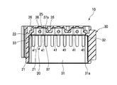
- FIG. 1 is a front view showing a joint connector according to the present embodiment.
- FIG. 2 is an exploded perspective view of the joint connector according to the present embodiment.
- FIG. 3 is a cross-sectional view taken along the line AA in FIG. 1 showing the joint connector according to the present embodiment.
- 4 is a cross-sectional view taken along the line BB in FIG. 1 showing the joint connector according to the present embodiment.
- FIG. 5 is a perspective view of a joint terminal constituting the joint connector.
- 6 (a) and 6 (b) are diagrams showing joint terminals constituting the joint connector, in which FIG. 6 (a) is a front view, and FIG. 6 (b) is a cross-sectional view of FIG. It is C sectional drawing.
- FIGS. 7 (a) to 7 (c) are views showing a housing constituting the joint connector, in which FIG. 7 (a) is a front view and FIG. 7 (b) is a DD in FIG. 7 (a).
- FIG. 7C is a cross-sectional view taken along line EE in FIG. 7A.
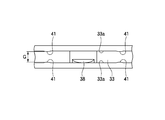
- FIG. 8 is an enlarged view of a portion F in FIG. 7A showing the press-fitting hole of the housing.
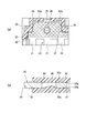
- 9 (a) and 9 (b) are views showing the press-fitted state of the support plate portion of the joint terminal into the press-fitting hole of the housing, and FIG. 9 (a) is a partial horizontal sectional view, FIG. 9B is a partial cross-sectional view in the vertical direction.
- FIG. 10A and 10B are views showing the press-fitted state of the support plate portion of the joint terminal into the press-fitting hole of the housing in the joint connector according to the reference example, and FIG. FIG. 10B is a partial cross-sectional view in the horizontal direction.
- FIG. 1 is a front view showing a joint connector according to this embodiment.
- FIG. 2 is an exploded perspective view of the joint connector according to the present embodiment.
- FIG. 3 is a cross-sectional view taken along the line AA in FIG. 1 showing the joint connector according to the present embodiment.
- 4 is a cross-sectional view taken along the line BB in FIG. 1 showing the joint connector according to the present embodiment.
- FIG. 5 is a perspective view of a joint terminal constituting the joint connector.
- 6 (a) and 6 (b) are diagrams showing joint terminals constituting the joint connector, in which FIG. 6 (a) is a front view, and FIG. 6 (b) is a cross-sectional view of FIG. It is C sectional drawing.
- FIG. 7 (a) to 7 (c) are views showing a housing constituting the joint connector, in which FIG. 7 (a) is a front view and FIG. 7 (b) is a DD in FIG. 7 (a).
- FIG. 7C is a cross-sectional view taken along line EE in FIG. 7A.
- FIG. 8 is an enlarged view of a portion F in FIG. 7A showing the press-fitting hole of the housing.
- 9 (a) and 9 (b) are views showing the press-fitted state of the support plate portion of the joint terminal into the press-fitting hole of the housing, and FIG. 9 (a) is a partial horizontal sectional view, FIG. 9B is a partial cross-sectional view in the vertical direction.
- the joint connector 10 includes two joint terminals 20 and a housing 30.
- hatching to the cross section of the joint terminal 20 is omitted in order to express the position of the rib 41.
- the joint connector 10 is to be mated and connected to the mating connector.
- the joint terminal 20 is electrically connected to the mating terminal of the mating connector.
- the joint terminal 20 is formed by pressing a conductive metal plate made of copper or a copper alloy, and includes a contact 21 and a support plate portion. 22.
- the joint terminal 20 is preferably subjected to tin plating on the surface for improving electrical connection performance.
- the support plate portion 22 is formed in a flat plate shape and is provided across the width direction of the joint terminal 20.
- a plurality of contacts 21 are formed on one side of the support plate portion 22.
- the contacts 21 come into contact with the mating terminals of the mating connector when connected to the mating connector, extend in the same direction from the support plate 22, and are arranged in parallel at intervals in the width direction of the joint terminal 20. ing.
- the support plate portion 22 has a plurality of protruding plate portions 24 protruding to the opposite side of the contact 21, and these protruding plate portions 24 are formed with locking holes 25 in the center portion in the width direction. Yes.
- Locking claw portions 26 are formed on both side portions of each protruding plate portion 24. The locking claw portion 26 protrudes obliquely toward the side opposite to the protruding direction of the protruding plate portion 24.
- the housing 30 is formed of, for example, a synthetic resin such as plastic, and the mating connector is inserted into the connection side with the mating connector. It is formed in a box shape having a recess 31. A wall 32 is provided on the opposite side of the fitting recess 31 of the housing 30 from the opening 31a.
- the wall portion 32 is formed with a press-fitting hole 33 into which the support plate portion 22 of the joint terminal 20 is press-fitted.
- the press-fitting holes 33 are formed along the width direction of the housing 30, and two press-fitting holes 33 are arranged in parallel to each other at positions spaced apart from each other in the vertical direction.
- the press-fitting hole 33 has locking recesses 37 at portions corresponding to the protruding plate portions 24 of the joint terminals 20, and the protruding plate portions 24 of the joint terminals 20 are fitted into these locking recesses 37. .
- a locking projection 38 is formed in the locking recess 37 on the surface facing the protruding plate portion 24 to be fitted, and the locking projection 38 locks the protruding plate portion 24 to be fitted. The protruding plate portion 24 is locked by entering the hole 25.
- the press-fitting hole 33 of the housing 30 includes a plurality of protrusions on both the upper and lower opposing surfaces 33 a facing the front and back surfaces 22 a of the support plate portion 22 press-fitted into the press-fitting hole 33.
- Ribs 41 are formed at opposing positions. These ribs 41 are formed along the press-fitting direction of the support plate part 22 into the press-fitting holes 33, and are arranged in parallel in a direction orthogonal to the press-fitting direction of the support plate part 22. Two of these ribs 41 are formed at a position sandwiching the locking projection 38 in the locking recess 37. Further, the upper and lower gap dimension G in the press-fitting hole 33 is slightly smaller than the thickness dimension T of the support plate portion 22 of the joint terminal 20.
- the joint terminal 20 is assembled to the housing 30 by press-fitting the support plate portion 22 from the opening 31 a side of the fitting recess 31 into the upper and lower press-fitting holes 33 of the housing 30.
- the joint terminal 20 When the joint terminal 20 is assembled in this way, the protruding plate portion 24 is fitted into the locking recess 37, so that the locking claw portion 26 of the protruding plate portion 24 is locked as shown in FIG. As shown in FIG. 9 (b), the locking projection 38 enters the locking hole 25 of the protruding plate portion 24 while biting into the side wall 37 a of the recess 37. As a result, the joint terminal 20 is maintained in a state where it is securely press-fitted into the press-fitting hole 33.
- the joint terminal 20 is supported vertically with respect to the wall portion 32 that is a fitting reference, and a plurality of contacts of the joint terminal 20 21 is disposed in the fitting recess 31 of the housing 30.
- the rib 41 contacts the front and back surfaces 22 a of the support plate portion 22. Since these ribs 41 are formed along the press-fitting direction of the support plate part 22 into the press-fitting holes 33, the ribs 41 are in line contact with the front and back surfaces 22a of the support plate part 22 (FIG. 9A). ), And the friction with respect to the support plate portion 22 is reduced. Further, when the support plate portion 22 of the joint terminal 20 is press-fitted into the press-fit hole 33, the ribs 41 formed on the upper and lower opposing surfaces 33a of the press-fit hole 33 serve as guides so that the support plate portion 22 of the joint terminal 20 is smooth. To the press-fitting hole 33.
- FIG. 10A and FIG. 10B are diagrams showing the press-fitted state of the support plate portion of the joint terminal into the press-fitting hole of the housing in the joint connector according to the reference example, and FIG. Is a partial cross-sectional view in the horizontal direction, and FIG. 10B is a partial cross-sectional view in the vertical direction.
- the joint terminal 20 attached to the housing 30 rattles or shakes. Therefore, there is a risk of poor fitting with the counterpart connector and poor contact with the counterpart terminal of the counterpart connector.
- the support plate portion 22 is press-fitted into the press-fitting hole 33 on both the opposing surfaces 33a of the press-fitting hole 33 facing the front and back surfaces 22a of the support plate portion 22.
- a plurality of ribs 41 along the direction are formed at intervals in a direction orthogonal to the press-fitting direction. For this reason, when the support plate part 22 of the joint terminal 20 is press-fitted into the press-fitting hole 33, the rib 41 comes into contact with the front and back surfaces 22 a of the support plate part 22.
- these ribs 41 are formed along the press-fitting direction of the support plate part 22 into the press-fitting holes 33, the ribs 41 are in line contact with the front and back surfaces 22 a of the support plate part 22. The friction with respect to the support plate part 22 can be reduced. Further, by controlling the projecting dimension of the rib 41 so that the gap dimension G in the press-fitting hole 33 is an appropriate dimension, the joint terminal 20 in which the support plate portion 22 is press-fitted into the press-fitting hole 33 is very easily rattled. It can be supported by the housing 30 without shaking.
- the press-fitting hole 33 is reduced while reducing friction with respect to the support plate part 22 press-fitted into the press-fitting hole 33.
- the joint terminal 20 can be reliably supported by the housing 30 by securing an appropriate pressure input to the support plate portion 22.
- the ribs 41 are formed on both opposing surfaces 33a of the press-fitting hole 33, but the ribs 41 may be formed on either one of the opposing surfaces 33a of the press-fitting hole 33. Even in this case, the rib 41 is in line contact with the support plate portion 22 on the facing surface 33a side where the rib 41 is formed, and friction when the support plate portion 22 is press-fitted into the press-fitting hole 33 can be reduced. Further, the mounting operation of the joint terminal 20 to the housing 30 can be facilitated.
- the present invention it is possible to support the joint terminal to the housing without rattling or shaking while ensuring good mounting workability of the joint terminal to the housing, and to facilitate the management of dimensions. it can.
- the present invention having this effect is useful for a joint connector having a joint terminal in a housing.
Landscapes
- Connector Housings Or Holding Contact Members (AREA)
- Connections Arranged To Contact A Plurality Of Conductors (AREA)
Abstract
平板状の支持板部(22)から相手方端子と接触するコンタクトが延在されたジョイント端子(20)と、ジョイント端子(20)の支持板部(22)が圧入される圧入孔(33)が形成された樹脂製のハウジング(30)と、を備え、圧入孔(33)には、支持板部(22)の表裏面(22a)に対向する対向面(33a)に、圧入孔(33)への支持板部(22)の圧入方向に沿う複数のリブ(41)が圧入方向と直交する方向に間隔をあけて形成されている。
Description
本発明は、ハウジング内にジョイント端子を備えたジョイントコネクタに関する。
従来より、相手方コネクタに接続されて導通状態を確保するジョイントコネクタとして、樹脂製のハウジング内にジョイント端子が圧入されたジョイントコネクタがある(例えば、特許文献1参照)。
上記のジョイントコネクタでは、ジョイント端子が圧入されるハウジングに形成された圧入孔は、その上下の隙間寸法がジョイント端子の厚さ寸法と略同等となるように成形される。圧入孔へ圧入されたジョイント端子は、その表裏面が圧入孔におけるジョイント端子と対向する上下の両方の対向面と面接触されて保持される。
ところで、ハウジングは、その製造時の誤差によって寸法にばらつきが生じることがある。そして、ジョイント端子の厚さに対して圧入孔の上下の隙間が小さいと、圧入孔の両対向面とジョイント端子の表裏面との面接触部分における摩擦が極めて大きくなる。これにより、ハウジングへジョイント端子を圧入するために大きな挿入力が必要となり、ジョイント端子のハウジングへの装着作業性が低下する。また、ジョイント端子の厚さに対して圧入孔の上下の隙間が大きいと、ハウジングに装着したジョイント端子ががたついたり振れが生じてしまい、相手方コネクタとの嵌合不良や相手方コネクタの相手方端子との接触不良が生じるおそれがある。
このように、ジョイントコネクタは、ジョイント端子のハウジングへの良好な装着作業性を確保しつつジョイント端子のがたつきや振れを抑えるために、ハウジングにおける圧入孔の上下の隙間寸法を高精度に管理しなければならなかった。
本発明は、上述した事情に鑑みてなされたものであり、その目的は、ハウジングへのジョイント端子の良好な装着作業性を確保しつつジョイント端子をハウジングにがたつきや振れなく支持させることができ、しかも、寸法の管理の容易化を図ることが可能なジョイントコネクタを提供することにある。
前述した目的を達成するために、本発明に係るジョイントコネクタは、下記(1)~(3)を特徴としている。
(1) 平板状の支持板部から相手方端子と接触するコンタクトが延在されたジョイント端子と、
該ジョイント端子の前記支持板部が圧入される圧入孔が形成された樹脂製のハウジングと、
を備え、
前記圧入孔には、前記支持板部の表裏面に対向する対向面の少なくとも一方に、前記圧入孔への前記支持板部の圧入方向に沿う複数のリブが前記圧入方向と直交する方向に間隔をあけて形成されていること。
(2) 上記(1)の構成のジョイントコネクタにおいて、前記リブが前記圧入孔の前記支持板部の表裏面に対向する対向面の両方に形成されていること。
(3) 上記(1)または(2)の構成のジョイントコネクタにおいて、前記圧入孔における隙間寸法が前記支持板部の厚さ寸法よりも僅かに小さくされていること。
(1) 平板状の支持板部から相手方端子と接触するコンタクトが延在されたジョイント端子と、
該ジョイント端子の前記支持板部が圧入される圧入孔が形成された樹脂製のハウジングと、
を備え、
前記圧入孔には、前記支持板部の表裏面に対向する対向面の少なくとも一方に、前記圧入孔への前記支持板部の圧入方向に沿う複数のリブが前記圧入方向と直交する方向に間隔をあけて形成されていること。
(2) 上記(1)の構成のジョイントコネクタにおいて、前記リブが前記圧入孔の前記支持板部の表裏面に対向する対向面の両方に形成されていること。
(3) 上記(1)または(2)の構成のジョイントコネクタにおいて、前記圧入孔における隙間寸法が前記支持板部の厚さ寸法よりも僅かに小さくされていること。
上記(1)の構成のジョイントコネクタは、圧入孔における支持板部の表裏面に対向する対向面の少なくとも一方に、圧入孔への支持板部の圧入方向に沿う複数のリブが圧入方向と直交する方向に間隔をあけて形成されている。このため、圧入孔へジョイント端子の支持板部を圧入する際に、支持板部の表裏面の少なくとも一方には、リブが接触することとなる。これらのリブは、圧入孔への支持板部の圧入方向に沿って形成されていることから、リブが支持板部の表裏面の少なくとも一方に対して線接触することとなる。このため、支持板部に対する摩擦を低減させることができる。また、リブの突出寸法を管理して圧入孔における隙間寸法を適正な寸法とすることで、極めて容易に、圧入孔へ支持板部を圧入したジョイント端子をがたつきや振れなくハウジングに支持させることができる。
上記(2)の構成のジョイントコネクタは、リブが圧入孔の支持板部の表裏面に対向する対向面の両方に形成されている。このため、リブが支持板部の表裏面の両方に対して線接触することとなり、支持板部に対する摩擦がさらに低減される。
上記(3)の構成のジョイントコネクタは、圧入孔における隙間寸法が支持板部の厚さ寸法よりも僅かに小さくされている。このため、圧入孔へ圧入される支持板部に対する摩擦を低減しつつ、圧入孔への支持板部の適度な圧入力を確保してジョイント端子を確実にハウジングに支持させることができる。
上記(2)の構成のジョイントコネクタは、リブが圧入孔の支持板部の表裏面に対向する対向面の両方に形成されている。このため、リブが支持板部の表裏面の両方に対して線接触することとなり、支持板部に対する摩擦がさらに低減される。
上記(3)の構成のジョイントコネクタは、圧入孔における隙間寸法が支持板部の厚さ寸法よりも僅かに小さくされている。このため、圧入孔へ圧入される支持板部に対する摩擦を低減しつつ、圧入孔への支持板部の適度な圧入力を確保してジョイント端子を確実にハウジングに支持させることができる。
本発明によれば、ハウジングへのジョイント端子の良好な装着作業性を確保しつつジョイント端子をハウジングにがたつきや振れなく支持させることができ、しかも、寸法の管理の容易化を図ることが可能なジョイントコネクタを提供できる。
以上、本発明について簡潔に説明した。更に、以下に説明される発明を実施するための形態(以下、「実施形態」という。)を添付の図面を参照して通読することにより、本発明の詳細は更に明確化されるであろう。
以下、本発明に係るジョイント端子の実施の形態の例を、図面を参照して説明する。
図1は、本実施形態に係るジョイントコネクタを示す正面図である。図2は、本実施形態に係るジョイントコネクタの分解斜視図である。図3は、本実施形態に係るジョイントコネクタを示す図1におけるA-A断面図である。図4は、本実施形態に係るジョイントコネクタを示す図1におけるB-B断面図である。図5は、ジョイントコネクタを構成するジョイント端子の斜視図である。図6(a)及び図6(b)は、ジョイントコネクタを構成するジョイント端子を示す図であって、図6(a)は正面図、図6(b)は図6(a)におけるC-C断面図である。図7(a)から図7(c)は、ジョイントコネクタを構成するハウジングを示す図であって、図7(a)は正面図、図7(b)は図7(a)におけるD-D断面図、図7(c)は図7(a)におけるE-E断面図である。図8は、ハウジングの圧入孔を示す、図7(a)におけるF部拡大図である。図9(a)及び図9(b)は、ハウジングの圧入孔へのジョイント端子の支持板部の圧入状態を示す図であって、図9(a)は一部の水平方向の断面図、図9(b)は一部の鉛直方向の断面図である。
図1から図4に示すように、ジョイントコネクタ10は、二つのジョイント端子20と、ハウジング30とを備えている。尚、図4においては、リブ41の位置を表現するためジョイント端子20の断面へのハッチングを省略している。
このジョイントコネクタ10は、相手方コネクタが嵌合接続されるもので、相手方コネクタが嵌合接続されることで、ジョイント端子20が、相手方コネクタの相手方端子と導通される。
図5及び図6(a)、図6(b)に示すように、ジョイント端子20は、銅または銅合金などからなる導電性の金属板をプレス加工したもので、コンタクト21と、支持板部22とを有している。なお、このジョイント端子20は、その表面に電気接続性能の向上のためのスズメッキを施すのが好ましい。
支持板部22は、平板状に形成されており、ジョイント端子20の幅方向にわたって設けられている。そして、この支持板部22の一方側に、複数のコンタクト21が形成されている。
コンタクト21は、相手方コネクタとの接続時に相手方コネクタの相手方端子と接触するもので、支持板部22から同一方向へ延在され、ジョイント端子20の幅方向に互いに間隔をあけて並列に複数配列されている。
支持板部22は、コンタクト21と反対側へ突出する複数の突出板部24を有しており、これらの突出板部24には、その幅方向の中央部分に係止孔25が形成されている。それぞれの突出板部24の両側部には、係止爪部26が形成されている。この係止爪部26は、突出板部24の突出方向と反対側へ向かって斜めに突出されている。
図7(a)~図7(c)に示すように、ハウジング30は、例えば、プラスチック等の合成樹脂から成形されたもので、相手方コネクタとの接続側に、相手方コネクタが挿し込まれる嵌合凹部31を有する箱状に形成されている。このハウジング30の嵌合凹部31の開口部31aと反対側には、壁部32が設けられている。
この壁部32には、ジョイント端子20の支持板部22が圧入される圧入孔33が穿設されている。圧入孔33は、ハウジング30の幅方向に沿って形成され、上下に間隔をあけて離間した位置に互いに平行に二つ配列されている。
圧入孔33は、ジョイント端子20の突出板部24に対応する部分に、係止凹部37を有しており、これらの係止凹部37に、ジョイント端子20の突出板部24が嵌合される。この係止凹部37には、嵌合される突出板部24との対向面に、係止突起38が形成されており、この係止突起38は、嵌合される突出板部24の係止孔25に入り込んで突出板部24を係止する。
図8に示すように、ハウジング30の圧入孔33には、この圧入孔33に圧入された支持板部22の表裏面22aに対向する上下の対向面33aの両方に、複数の突条からなるリブ41が対向位置に形成されている。これらのリブ41は、圧入孔33への支持板部22の圧入方向に沿って形成されており、支持板部22の圧入方向と直交する方向に間隔をあけて並列されている。これらのリブ41は、係止凹部37における係止突起38を挟んだ位置に二つずつ形成されている。また、圧入孔33における上下の隙間寸法Gは、ジョイント端子20の支持板部22の厚さ寸法Tよりも僅かに小さくされている。
上記のハウジング30において、ジョイント端子20は、ハウジング30の上下のそれぞれの圧入孔33へ嵌合凹部31の開口部31a側から支持板部22を圧入することでハウジング30に組み付けられる。
このようにジョイント端子20を組み付けると、係止凹部37に突出板部24が嵌合されることで、図9(a)に示すように、突出板部24の係止爪部26が係止凹部37の側壁37aに食い込むとともに、図9(b)に示すように、突出板部24の係止孔25に係止突起38が入り込む。これにより、ジョイント端子20は、圧入孔33に確実に圧入された状態に維持される。
上記のように、圧入孔33にジョイント端子20の支持板部22を圧入することで、嵌合基準である壁部32に対してジョイント端子20が垂直に支持され、ジョイント端子20の複数のコンタクト21がハウジング30の嵌合凹部31内に配置される。
また、圧入孔33へジョイント端子20の支持板部22を圧入する際に、支持板部22の表裏面22aには、リブ41が接触する。これらのリブ41は、圧入孔33への支持板部22の圧入方向に沿って形成されていることから、リブ41は、支持板部22の表裏面22aに対して線接触(図9(a)における網目箇所参照)することとなり、支持板部22に対する摩擦が低減される。また、圧入孔33へジョイント端子20の支持板部22を圧入する際に、圧入孔33の上下の対向面33aに形成されたリブ41がガイドとなってジョイント端子20の支持板部22が円滑に圧入孔33へ導かれる。
ここで、図10(a)及び図10(b)は、参考例に係るジョイントコネクタにおけるハウジングの圧入孔へのジョイント端子の支持板部の圧入状態を示す図であって、図10(a)は一部の水平方向の断面図、図10(b)は一部の鉛直方向の断面図である。
図10(a)及び図10(b)に示すように、リブ41が形成されていない圧入孔33にジョイント端子20の支持板部22を圧入する場合では、支持板部22の表裏面22aと圧入孔33の対向面33aとがそれぞれ面接触(図10(a)における網目箇所参照)することとなる。この場合、支持板部22の厚さ寸法Tに対して圧入孔33の対向面33aの隙間寸法Gが小さいと、圧入孔33の対向面33aと支持板部22の表裏面22aとの面接触部分における摩擦が極めて大きくなる。このため、ハウジング30の圧入孔33へジョイント端子20の支持板部22を圧入するために大きな挿入力が必要となり、ジョイント端子20のハウジング30への装着作業性が低下する。
また、ジョイント端子20の支持板部22の厚さ寸法Tに対して圧入孔33の対向面33aの隙間寸法Gが大きいと、ハウジング30に装着したジョイント端子20ががたついたり振れが生じてしまい、相手方コネクタとの嵌合不良や相手方コネクタの相手方端子との接触不良が生じるおそれがある。
これに対して、本実施形態に係るジョイントコネクタ10によれば、圧入孔33における支持板部22の表裏面22aに対向する対向面33aの両方に、圧入孔33への支持板部22の圧入方向に沿う複数のリブ41が圧入方向と直交する方向に間隔をあけて形成されている。このため、圧入孔33へジョイント端子20の支持板部22を圧入する際に、支持板部22の表裏面22aには、リブ41が接触することとなる。これらのリブ41は、圧入孔33への支持板部22の圧入方向に沿って形成されていることから、リブ41が支持板部22の表裏面22aに対して線接触することとなるので、支持板部22に対する摩擦を低減させることができる。また、リブ41の突出寸法を管理して圧入孔33における隙間寸法Gを適正な寸法とすることで、極めて容易に、圧入孔33へ支持板部22を圧入したジョイント端子20をがたつきや振れなくハウジング30に支持させることができる。
また、圧入孔33における隙間寸法Gが支持板部22の厚さ寸法Tよりも僅かに小さくされているので、圧入孔33へ圧入される支持板部22に対する摩擦を低減しつつ、圧入孔33への支持板部22の適度な圧入力を確保してジョイント端子20を確実にハウジング30に支持させることができる。
なお、上記の実施形態では、圧入孔33における両方の対向面33aにリブ41を形成したが、圧入孔33の対向面33aのいずれか一方にリブ41を形成しても良い。この場合においても、リブ41を形成した対向面33a側では、リブ41が支持板部22と線接触することとなり、圧入孔33へ支持板部22を圧入する際の摩擦を低減することができ、ハウジング30へのジョイント端子20の装着作業の容易化を図ることができる。
尚、本発明は、上述した実施形態に限定されるものではなく、適宜、変形、改良、等が可能である。その他、上述した実施形態における各構成要素の材質、形状、寸法、数、配置箇所、等は本発明を達成できるものであれば任意であり、限定されない。
ここで、上述した本発明に係るジョイントコネクタの実施形態の特徴をそれぞれ以下[1]~[3]に簡潔に纏めて列記する。
[1] 平板状の支持板部(22)から相手方端子と接触するコンタクト(21)が延在されたジョイント端子(20)と、
該ジョイント端子の前記支持板部が圧入される圧入孔(33)が形成された樹脂製のハウジング(30)と、
を備え、
前記圧入孔には、前記支持板部の表裏面に対向する対向面の少なくとも一方に、前記圧入孔への前記支持板部の圧入方向に沿う複数のリブ(41)が前記圧入方向と直交する方向に間隔をあけて形成されているジョイントコネクタ。
[2] 前記リブが前記圧入孔の前記支持板部の表裏面に対向する対向面の両方に形成されている上記[1]に記載のジョイントコネクタ。
[3] 前記圧入孔における隙間寸法(G)が前記支持板部の厚さ寸法(T)よりも僅かに小さくされている上記[1]または[2]に記載のジョイントコネクタ。
該ジョイント端子の前記支持板部が圧入される圧入孔(33)が形成された樹脂製のハウジング(30)と、
を備え、
前記圧入孔には、前記支持板部の表裏面に対向する対向面の少なくとも一方に、前記圧入孔への前記支持板部の圧入方向に沿う複数のリブ(41)が前記圧入方向と直交する方向に間隔をあけて形成されているジョイントコネクタ。
[2] 前記リブが前記圧入孔の前記支持板部の表裏面に対向する対向面の両方に形成されている上記[1]に記載のジョイントコネクタ。
[3] 前記圧入孔における隙間寸法(G)が前記支持板部の厚さ寸法(T)よりも僅かに小さくされている上記[1]または[2]に記載のジョイントコネクタ。
本発明を詳細にまた特定の実施態様を参照して説明したが、本発明の精神と範囲を逸脱することなく様々な変更や修正を加えることができることは当業者にとって明らかである。
本出願は、2013年5月10日出願の日本特許出願(特願2013-100758)に基づくものであり、その内容はここに参照として取り込まれる。
本発明によれば、ハウジングへのジョイント端子の良好な装着作業性を確保しつつジョイント端子をハウジングにがたつきや振れなく支持させることができ、しかも、寸法の管理の容易化を図ることができる。この効果を奏する本発明は、ハウジング内にジョイント端子を備えたジョイントコネクタに関して有用である。
10 ジョイントコネクタ
20 ジョイント端子
21 コンタクト
22 支持板部
22a 表裏面
30 ハウジング
33 圧入孔
33a 対向面
41 リブ
G 隙間寸法
T 厚さ寸法
20 ジョイント端子
21 コンタクト
22 支持板部
22a 表裏面
30 ハウジング
33 圧入孔
33a 対向面
41 リブ
G 隙間寸法
T 厚さ寸法
Claims (3)
- 平板状の支持板部から相手方端子と接触するコンタクトが延在されたジョイント端子と、
該ジョイント端子の前記支持板部が圧入される圧入孔が形成された樹脂製のハウジングと、
を備え、
前記圧入孔には、前記支持板部の表裏面に対向する対向面の少なくとも一方に、前記圧入孔への前記支持板部の圧入方向に沿う複数のリブが前記圧入方向と直交する方向に間隔をあけて形成されているジョイントコネクタ。 - 前記リブが前記圧入孔の前記支持板部の表裏面に対向する対向面の両方に形成されている請求項1に記載のジョイントコネクタ。
- 前記圧入孔における隙間寸法が前記支持板部の厚さ寸法よりも僅かに小さくされている請求項1または請求項2に記載のジョイントコネクタ。
Priority Applications (1)
| Application Number | Priority Date | Filing Date | Title |
|---|---|---|---|
| CN201480025533.3A CN105191017B (zh) | 2013-05-10 | 2014-04-24 | 接合连接器 |
Applications Claiming Priority (2)
| Application Number | Priority Date | Filing Date | Title |
|---|---|---|---|
| JP2013100758A JP6093645B2 (ja) | 2013-05-10 | 2013-05-10 | ジョイントコネクタ |
| JP2013-100758 | 2013-05-10 |
Publications (1)
| Publication Number | Publication Date |
|---|---|
| WO2014181703A1 true WO2014181703A1 (ja) | 2014-11-13 |
Family
ID=51867185
Family Applications (1)
| Application Number | Title | Priority Date | Filing Date |
|---|---|---|---|
| PCT/JP2014/061638 Ceased WO2014181703A1 (ja) | 2013-05-10 | 2014-04-24 | ジョイントコネクタ |
Country Status (3)
| Country | Link |
|---|---|
| JP (1) | JP6093645B2 (ja) |
| CN (1) | CN105191017B (ja) |
| WO (1) | WO2014181703A1 (ja) |
Families Citing this family (2)
| Publication number | Priority date | Publication date | Assignee | Title |
|---|---|---|---|---|
| JP7311320B2 (ja) * | 2019-06-21 | 2023-07-19 | 矢崎総業株式会社 | ジョイントコネクタ |
| JP7725152B2 (ja) * | 2023-04-10 | 2025-08-19 | 矢崎総業株式会社 | コネクタ |
Citations (3)
| Publication number | Priority date | Publication date | Assignee | Title |
|---|---|---|---|---|
| JPH0662491U (ja) * | 1993-02-12 | 1994-09-02 | ホシデン株式会社 | ショートプラグ |
| JP2005116472A (ja) * | 2003-10-10 | 2005-04-28 | Sumitomo Wiring Syst Ltd | ジョイントコネクタ及びジョイントコネクタの製造方法 |
| JP2005116473A (ja) * | 2003-10-10 | 2005-04-28 | Sumitomo Wiring Syst Ltd | ジョイントコネクタ、ジョイント端子、及びジョイント端子の製造方法 |
Family Cites Families (2)
| Publication number | Priority date | Publication date | Assignee | Title |
|---|---|---|---|---|
| US5147218A (en) * | 1991-04-12 | 1992-09-15 | Minnesota Mining And Manufacturing Company | Pluggable modular splicing connector and bridging adapter |
| JP2004311044A (ja) * | 2003-04-02 | 2004-11-04 | Sumitomo Wiring Syst Ltd | コネクタ |
-
2013
- 2013-05-10 JP JP2013100758A patent/JP6093645B2/ja active Active
-
2014
- 2014-04-24 CN CN201480025533.3A patent/CN105191017B/zh active Active
- 2014-04-24 WO PCT/JP2014/061638 patent/WO2014181703A1/ja not_active Ceased
Patent Citations (3)
| Publication number | Priority date | Publication date | Assignee | Title |
|---|---|---|---|---|
| JPH0662491U (ja) * | 1993-02-12 | 1994-09-02 | ホシデン株式会社 | ショートプラグ |
| JP2005116472A (ja) * | 2003-10-10 | 2005-04-28 | Sumitomo Wiring Syst Ltd | ジョイントコネクタ及びジョイントコネクタの製造方法 |
| JP2005116473A (ja) * | 2003-10-10 | 2005-04-28 | Sumitomo Wiring Syst Ltd | ジョイントコネクタ、ジョイント端子、及びジョイント端子の製造方法 |
Also Published As
| Publication number | Publication date |
|---|---|
| CN105191017A (zh) | 2015-12-23 |
| JP6093645B2 (ja) | 2017-03-08 |
| JP2014220211A (ja) | 2014-11-20 |
| CN105191017B (zh) | 2017-06-16 |
Similar Documents
| Publication | Publication Date | Title |
|---|---|---|
| JP5946804B2 (ja) | コネクタ | |
| JP6278841B2 (ja) | コネクタ | |
| US20160093967A1 (en) | Connector | |
| CN106067627A (zh) | 连接器 | |
| JP2017204325A (ja) | 基板用コネクタ | |
| JP2016177955A (ja) | 電気コネクタ | |
| JP6600261B2 (ja) | プレスフィット端子 | |
| TWI659574B (zh) | 電連接器 | |
| JP2018006246A (ja) | 端子モジュール、およびコネクタ | |
| TW201803218A (zh) | 表面安裝型連接器 | |
| CN105048149A (zh) | 连接器 | |
| JP6093645B2 (ja) | ジョイントコネクタ | |
| JP2012256477A (ja) | 基板用コネクタの取付構造 | |
| JP7256094B2 (ja) | ジョイントコネクタ | |
| JP2012243676A (ja) | コネクタ | |
| JP2016162605A (ja) | コネクタユニット | |
| JP5999509B2 (ja) | カードエッジコネクタ | |
| JP2013143286A (ja) | 基板用コネクタ | |
| JP5999638B2 (ja) | 電子ユニット取付構造 | |
| JP5806128B2 (ja) | バスバー組み付け構造 | |
| JP5934630B2 (ja) | ジョイントコネクタ | |
| JP2014203694A (ja) | コネクタ | |
| WO2021153212A1 (ja) | 端子、端子連結体、及び基板用コネクタ | |
| CN106252929A (zh) | 连接器、以及扁平电路体与连接器的连接构造 | |
| WO2014007241A1 (ja) | コネクタ構造 |
Legal Events
| Date | Code | Title | Description |
|---|---|---|---|
| WWE | Wipo information: entry into national phase |
Ref document number: 201480025533.3 Country of ref document: CN |
|
| 121 | Ep: the epo has been informed by wipo that ep was designated in this application |
Ref document number: 14794326 Country of ref document: EP Kind code of ref document: A1 |
|
| NENP | Non-entry into the national phase |
Ref country code: DE |
|
| 122 | Ep: pct application non-entry in european phase |
Ref document number: 14794326 Country of ref document: EP Kind code of ref document: A1 |