WO2014181675A1 - Unité de pince - Google Patents
Unité de pince Download PDFInfo
- Publication number
- WO2014181675A1 WO2014181675A1 PCT/JP2014/061231 JP2014061231W WO2014181675A1 WO 2014181675 A1 WO2014181675 A1 WO 2014181675A1 JP 2014061231 W JP2014061231 W JP 2014061231W WO 2014181675 A1 WO2014181675 A1 WO 2014181675A1
- Authority
- WO
- WIPO (PCT)
- Prior art keywords
- clip
- end side
- arm
- locked
- proximal end
- Prior art date
Links
Images


Classifications
-
- A—HUMAN NECESSITIES
- A61—MEDICAL OR VETERINARY SCIENCE; HYGIENE
- A61B—DIAGNOSIS; SURGERY; IDENTIFICATION
- A61B17/00—Surgical instruments, devices or methods, e.g. tourniquets
- A61B17/12—Surgical instruments, devices or methods, e.g. tourniquets for ligaturing or otherwise compressing tubular parts of the body, e.g. blood vessels, umbilical cord
- A61B17/122—Clamps or clips, e.g. for the umbilical cord
-
- A—HUMAN NECESSITIES
- A61—MEDICAL OR VETERINARY SCIENCE; HYGIENE
- A61B—DIAGNOSIS; SURGERY; IDENTIFICATION
- A61B17/00—Surgical instruments, devices or methods, e.g. tourniquets
- A61B17/12—Surgical instruments, devices or methods, e.g. tourniquets for ligaturing or otherwise compressing tubular parts of the body, e.g. blood vessels, umbilical cord
- A61B17/128—Surgical instruments, devices or methods, e.g. tourniquets for ligaturing or otherwise compressing tubular parts of the body, e.g. blood vessels, umbilical cord for applying or removing clamps or clips
- A61B17/1285—Surgical instruments, devices or methods, e.g. tourniquets for ligaturing or otherwise compressing tubular parts of the body, e.g. blood vessels, umbilical cord for applying or removing clamps or clips for minimally invasive surgery
-
- A—HUMAN NECESSITIES
- A61—MEDICAL OR VETERINARY SCIENCE; HYGIENE
- A61B—DIAGNOSIS; SURGERY; IDENTIFICATION
- A61B17/00—Surgical instruments, devices or methods, e.g. tourniquets
- A61B17/08—Wound clamps or clips, i.e. not or only partly penetrating the tissue ; Devices for bringing together the edges of a wound
- A61B17/083—Clips, e.g. resilient
Definitions
- the present invention relates to a clip unit used for ligating tissues.
- This application claims priority on May 7, 2013 based on the US provisional application 61 / 820,219 provisionally applied to the United States, and uses the content here.
- the clip unit described in Patent Document 1 includes a claw, a pressing tube, and a connecting plate.
- the nail is formed by bending the middle part into an ⁇ shape and forming both end parts in a nail shape.
- the claw arm portion is configured to open small by its own elastic restoring force in the released natural state.
- the connecting plate is provided with a hole at the proximal end and a hook portion at the distal end. The hook portion is hooked and attached to the proximal end loop portion of the claw in the holding tube. At this time, the ⁇ portion of the nail is not drawn deeply into the holding tube, and the arm portion of the nail can be opened small.
- the clip unit of Patent Document 1 configured as described above is introduced into the body using an endoscopic ligation apparatus.
- the endoscope ligation apparatus includes an introduction tube, a coil sheath, an operation wire (a linear member), an operation unit body, and a slider.
- the coil sheath is inserted into the introduction tube so as to freely advance and retract.
- the operation wire (linear member) is inserted into the coil sheath so as to be able to advance and retract.
- the operation part main body is attached to the proximal end of the coil sheath.
- the slider is attached to the proximal end of the operation wire via a pipe, and is configured to be slidable with the operation unit main body.
- the aforementioned clip unit is attached to the tip of the operation wire.
- the operation wire is passed through the hole of the connecting plate and the midway portion is folded back.
- the portions on both sides of the operation wire that has become two by turning the midway part are inserted in a coil sheath so as to be able to advance and retreat in a parallel state.
- Sliders are fixed to the base end portions on both sides of the operation wire.
- Pipes are fitted to both side base ends of the operation wire.
- the clip unit and endoscope ligation apparatus configured as described above are used as follows.
- the clip unit is kept in the introduction tube.
- the introduction tube of the endoscope ligation apparatus thus configured is inserted into the endoscope channel that has been previously inserted into the body cavity.
- the introducing tube is pulled toward the proximal side, and the clip unit is protruded from the leading end of the introducing tube.
- the slider toward the hand side with a light force
- the ⁇ part of the nail is pulled into the holding tube, and the nail is opened more widely.
- the introduction tube is pushed into the endoscope, and the opened nail is pressed against the target bleeding site in the body cavity.
- This invention is made
- the clip unit according to the first aspect of the present invention includes a first arm portion, a second arm portion, and a center located between the proximal end portion of the first arm portion and the proximal end portion of the second arm portion.
- a clip body having a portion and a cylindrical shape capable of accommodating the clip body, and the clip body is deformed as the central portion, the first arm portion, and the second arm portion move to the proximal end side.
- a pressing tube that allows the distal end portion of the first arm portion and the distal end portion of the second arm portion to approach each other, a locking portion that protrudes from the inner peripheral surface of the proximal end side of the pressing tube, and the first arm portion And can move forward with respect to the pressing tube in a state of being positioned on the distal end side of the locking portion in the pressing tube and beyond the locking portion on the proximal side with respect to the locking portion.
- the state of moving to the presser tube by engaging with the locking portion Comprising a first engaged portion which forward is restricted, the.
- the second locked portion that protrudes in the direction opposite to the first locked portion from the side surface of the second arm portion is further provided. You may prepare. As the first arm portion and the second arm portion approach each other by the pressing tube, the first engaged portion and the second engaged portion approach each other, so that the first engaged portion The stop portion may be movable to the proximal end side beyond the locking portion.
- the locking portion may be provided at a proximal end of the pressing tube. In a state where the first locked portion moves to the proximal end side beyond the locking portion, at least a part of the center portion may protrude toward the proximal end side from the pressing tube.
- the pressing tube may be formed in a cylindrical shape.
- the locking portion may be formed over the entire circumference of the inner peripheral surface of the pressing tube, and the edge of the locking portion may be formed in a circular shape coaxial with the pressing tube.
- the first locked portion includes a front end side end surface composed of a surface substantially orthogonal to the longitudinal axis of the clip body, and You may have the base end side end surface formed in the taper shape.
- the amount of force required for the first locked portion to move over the locking portion from the proximal end side toward the distal end side by bringing the distal end side end surface into contact with the locking portion is It may be larger than the amount of force required for the first locked portion to get over the locking portion from the distal end side toward the proximal end side by contacting the side end surface.
- an elastic member for urging the clip main body in a direction of moving forward with respect to the pressing tube is provided in the pressing tube. Also good. In a state in which the first locked portion is positioned on the tip side of the locking portion in the pressing tube, the clip body is moved in a direction to advance with respect to the pressing tube by the biasing of the elastic member. Also good.
- the target tissue can be grasped again.
- FIG. 4 is a schematic perspective view taken along the cutting line A1-A1 in FIG. It is a figure which shows typically the state which looked at the clip unit of FIG.
- FIG. 5 is a view taken along the cutting line A2-A2 in FIG. It is sectional drawing of the plane which showed typically the fracture
- FIG. 10 is a view taken along a cutting line A3-A3 in FIG. It is a schematic diagram explaining the procedure using the endoscope treatment tool of FIG. It is a schematic diagram showing the force required for pulling back a slider with respect to the moving amount which pulls back a slider in the endoscope treatment tool of FIG. It is sectional drawing of the side which showed typically the same endoscope treatment tool when the clip unit which concerns on one Embodiment of this invention is a contact state.
- FIG. 2 is a plan sectional view schematically showing a breaking mechanism in a broken state in the procedure using the endoscope treatment tool of FIG. 1. It is the figure fractured
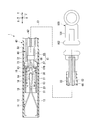
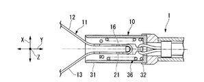
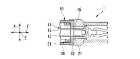
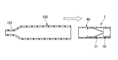
- the endoscope treatment tool 1 that is a ligation apparatus includes a clip unit (hereinafter also abbreviated as “clip”) 10 and a treatment tool body 40.
- the clip 10 can be attached to and detached from the distal end portion of the treatment instrument main body 40.
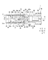
- 1 and 2 are cross-sectional views of a plane passing through an axis C1 of a presser tube 31 described later.
- FIG. 1 and 2 are cross-sectional views of a plane passing through an axis C1 of a presser tube 31 described later.
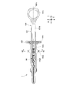
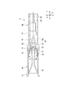
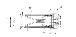
- FIG. 3 is a side sectional view of the clip 10 of the endoscope treatment tool 1.
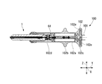
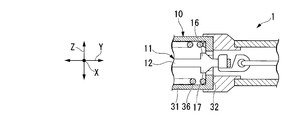
- FIG. 4 is a cross-sectional view of the side surface of the proximal end portion of the endoscope treatment tool 1.
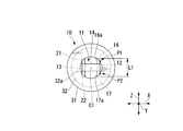
- FIG. 5 is a plan sectional view of the proximal end portion of the endoscope treatment tool 1.
- the clip 10 includes a clip body 11, a holding tube 31, and a helical spring (elastic member) 36.
- the holding tube 31 is formed in a cylindrical shape and accommodates the proximal end portion of the clip body 11.
- the helical spring 36 is accommodated in the holding tube 31.
- These members constituting the clip 10 including the clip body 11 are made of a material such as cobalt chrome alloy, titanium, stainless steel or the like.
- the clip 10 is configured to allow observation under MRI (nuclear magnetic resonance imaging) fluoroscopy.
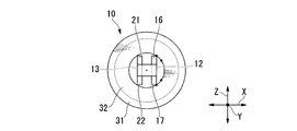
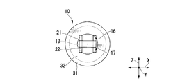
- the clip main body 11 has a first arm portion 12, a second arm portion 13, and a central portion 14.
- the first arm portion 12 and the second arm portion 13 are arranged side by side so as to extend from the proximal end side toward the distal end side and to face each other.
- the central portion 14 is located between the proximal end portion of the first arm portion 12 and the proximal end portion of the second arm portion 13.
- the first arm portion 12 and the second arm portion 13 are formed so as to be separated from each other in the natural state from the proximal end side toward the distal end side.
- a claw 12 a extending toward the second arm portion 13 side is formed at the distal end portion of the first arm portion 12.
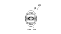
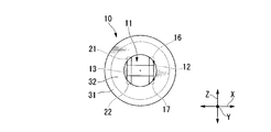
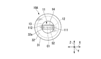
- the first arm portion 12 and the second arm portion 13 are formed in a rounded shape so that the cross-sectional shape orthogonal to the longitudinal direction on the distal end side becomes an arc shape as shown in FIG. More specifically, the center part in the orthogonal direction Z, which will be described later, on the outer surfaces of the arm parts 12 and 13 is formed in a curved surface that is convex outward. As a result, the first arm portion 12 and the second arm portion 13 are improved in strength against bending, and the friction resistance with respect to the outer tube 50 described later can be reduced, so that the forward and backward movement can be performed smoothly.
- first locked portions 16 and 17 of the clip (Description of configuration: first locked portions 16 and 17 of the clip 10)
- the facing direction X in which the first arm portion 12 and the second arm portion 13 face each other the axial direction Y parallel to the axis C ⁇ b> 1 of the pressing tube 31, and the facing direction X and the axial direction Y, respectively.
- An orthogonal direction Z that is orthogonal is defined.
- two first locked portions 16 and 17 are provided at the proximal end portion of the first arm portion 12.
- the first locked portions 16 and 17 are provided so as to protrude in the orthogonal direction Z from the side surface of the first arm portion 12 on the reference surface S1 parallel to the axis line (center axis line) C1 of the presser tube 31.
- FIG. 2 is a diagram viewed in a direction orthogonal to the reference plane S1.
- the first locked portion 16 and the first locked portion 17 are formed so as to be line-symmetric with respect to the axis C1.
- the base end surface 16a of the first locked portion 16 is inclined so as to be separated from the first arm portion 12 (center axis C1) toward the distal end side.
- the front end surface 16 b of the first locked portion 16 is orthogonal to the axial direction Y.
- the proximal end surface 17a and the distal end surface 17b of the first locked portion 17 are formed so as to be symmetrical with respect to the proximal end surface 16a and the distal end surface 16b of the first locked portion 16 and the axis C1.
- protrusions 18 and 19 of the clip 10 As shown in FIGS. 1 and 2, two protrusions 18 and 19 are provided on the distal end side of the first locked portion 16 and 17 in the first arm portion 12.
- the protrusions 18 and 19 protrude in the orthogonal direction Z from the side surface of the first arm portion 12.
- the protrusion 18 and the protrusion 19 are formed so as to be line symmetric with respect to the axis C1 in plan view.
- the length that the protrusions 18 and 19 protrude from the first arm portion 12 is longer than the length that the first locked portions 16 and 17 protrude from the first arm portion 12 in the orthogonal direction Z.
- a claw 13 a extending toward the first arm portion 12 is formed at the distal end portion of the second arm portion 13.
- the second arm portion 13 includes second locked portions 21 and 22 and protruding portions 23 and 24 formed in the same manner as the first locked portions 16 and 17 and the protruding portions 18 and 19 of the first arm portion 12. (See FIG. 7 for the second locked portion 22 and the protrusion 24 is not shown). That is, the second locked portions 21 and 22 protrude from the side surface of the second arm portion 13 in the orthogonal direction Z that is a direction away from the first arm portion 12.
- the protrusions 23 and 24 are provided on the distal end side of the second arm portion 13 relative to the second locked portions 21 and 22 so as to protrude from the side surface of the second arm portion 13 in the orthogonal direction Z.
- the second locked portions 21 and 22 and the protrusions 23 and 24, and the first locked portions 16 and 17 and the protrusions 18 and 19 are arranged side by side in the facing direction X, respectively. That is, in the plan view shown in FIG. 2, the second locked portions 21 and 22 overlap the first locked portions 16 and 17, and the protrusions 23 and 24 overlap the protrusions 18 and 19.
- the first arm portion 12 and the second arm portion 13 are formed at positions that are line-symmetric with respect to the axis C1.
- the clip body 11 is made of a plate material made of a cobalt chrome alloy or the like.
- the arm portions 12 and 13, the central portion 14, the first locked portions 16 and 17, the second locked portions 21 and 22, the protruding portion 18, 19, 23, and 24 are punched into a flat shape. Then, the punched member is bent at the connecting portion between the first arm portion 12 and the central portion 14 and the connecting portion between the second arm portion 13 and the central portion 14 so as to be C-shaped in a side view. It is integrally formed.
- a locking portion 32 protrudes from the inner peripheral surface of the proximal end portion of the presser tube 31 over the entire circumference.
- the edge portion 32 a on the axis C ⁇ b> 1 side of the locking portion 32 is formed in a circular shape coaxial with the presser tube 31.
- the base end face 32 b (base end side end face) and the tip end face 32 c (tip end side end face) of the locking portion 32 are orthogonal to the axial direction Y.
- each of the first locked portions 16 and 17 is set so as to overlap the locking portion 32 when viewed from the axial direction Y. That is, in the state shown in FIG.
- the edge portion 32a is opposed to the first locked portions 16 and 17 at the positions P1 and P2, and the heights of the positions P1 and P2 of the edge portion 32a in the orthogonal direction Z (in FIG. 7).
- the length L1 of the first locked portions 16 and 17 is set to be longer than the length of the line segment connecting the position P1 and the position P2.
- a tapered surface 31 a is formed over the entire circumference at the tip of the inner peripheral surface of the pressing tube 31.
- the taper surface 31a increases in diameter toward the tip side.
- the holding tube 31 and the locking portion 32 are integrally formed of a material such as 64 titanium alloy (Ti-6AL-4V) or cobalt chrome alloy.
- the end winding portion 36 b is provided at the tip of the helical spring 36.
- the end turn 36b is formed to have a smaller inner diameter than other portions of the helical spring 36.
- the distal end portion is locked to the protrusions 18, 19, 23, and 24, and the base end portion is locked to the locking portion 32.
- the proximal end portion of the helical spring 36 and the locking portion 32 may be fixed by welding or the like.
- a portion of the first arm portion 12 that is proximal to the protrusions 18 and 19, a portion of the second arm portion 13 that is proximal to the protrusions 23 and 24, and the central portion 14. Can be inserted.
- the protrusions 18, 19, 23, 24 move to the proximal end side, the protrusions 18, 19, 23, 24 are locked to the end turn part 36 b of the helical spring 36.
- the helical spring 36 does not include the end winding portion 36b, the same effect can be obtained by attaching another member such as a washer to the tip of the helical spring 36.
- the proximal end portion of the first arm portion 12, the proximal end portion of the second arm portion 13, and the central portion 14 are from the locking portion 32 in the presser tube 31. Is also housed on the tip side.
- the first locked portions 16 and 17 and the second locked portions 21 and 22 are not in contact with the locking portion 32 of the presser tube 31.
- the strands 36a adjacent to each other in the axial direction Y of the helical spring 36 are separated from each other, and the helical spring 36 is slightly compressed in the axial direction Y from the natural state.
- the distal end portion of the first arm portion 12 and the distal end portion of the second arm portion 13 of the clip body 11 are in an open state that is relatively separated from each other.
- the 1st to-be-latched part 16 contacts the part of the position P1 in the edge part 32a.
- the portion at the position P1 of the edge portion 32a and the first locked portion 16 are in point contact.
- the 1st arm part 12 is moved to the base end side with respect to the holding
- the portion of the edge portion 32a at the position P2 and the first locked portion 17 are in point contact.
- the positions in the orthogonal direction Z of the edge portion 32a corresponding to the positions P1 and P2 are shown as positions Q1 and Q2 in FIG.
- the treatment instrument main body 40 includes an outer tube 50, an insertion portion 60 that is inserted into the outer tube 50 so as to be able to advance and retreat, and an operation portion that is attached to a proximal end portion of the insertion portion 60.
- the outer tube 50 can be formed of a fluororesin such as PTFE (polytetrafluoroethylene) or a resin material such as HDPE (high density polyethylene).
- the insertion part 60 includes a sheath part 61, an operation wire 62, and a connecting member 63.
- the operation wire 62 is inserted into the sheath portion 61 so as to be able to advance and retract.
- the connecting member 63 is connected to the distal end portion of the operation wire 62.
- the connecting member 63 is provided to be rotatable about an axis parallel to the facing direction X with respect to the operation wire 62.
- the sheath portion 61 has a coil sheath 66 and a tip member (stopper portion) 67 fixed to the tip portion of the coil sheath 66.
- the coil sheath 66 is made of stainless steel such as SUS301 having high compressive strength. As the coil sheath 66, a coil formed by winding a wire (not shown) closely in the axial direction Y can be used. The coil sheath 66 has flexibility and is strong against compressive force in the axial direction Y. The inner diameter of the coil sheath 66 is substantially equal to the inner diameter of the helical spring 36.
- the tip member 67 is formed in a cylindrical shape with stainless steel or the like, and the inner diameter is smaller than the inner diameter of the coil sheath 66.
- the outer diameter of the tip member 67 is larger than that of the coil sheath 66 and the holding tube 31.
- a concave portion 67 a is formed on the outer peripheral surface of the base end portion of the distal end member 67 by reducing the outer diameter.
- the inner peripheral surface of the distal end portion of the sheath portion 61 is formed such that the inner diameter of the distal end member 67 on the distal end side of the coil sheath 66 with respect to the coil sheath 66 is reduced.
- a stepped portion 68 is formed at the connecting portion.
- the inner diameter of the distal end member 67 is such that the distal end member 67 engages with the first locked portions 16 and 17 and the second locked portions 21 and 22 when the clip 10 is locked as described later. It is formed as large as possible.
- distal end member 67 of treatment instrument body 40 On the inner peripheral surface of the distal end portion of the distal end member 67, a recess is formed over the entire circumference, and the distal end side is a support member 69 from the recess.
- the support member 69 is formed in a cylindrical shape.
- the inner diameter of the support member 69 is slightly larger than the outer diameter of the pressing tube 31 and can receive the proximal end of the pressing tube 31.
- the surface facing forward is a tip support surface (tip surface) 67b.
- the distal end support surface 67 b can contact the proximal end surface of the presser tube 31.
- the clip 10 is disposed on the distal end side of the sheath portion 61.
- the support member 69 can support the outer peripheral surface of the pressing tube 31 in contact with the tip support surface 67b. With these configurations, the wobbling of the clip 10 with respect to the support member 69 can be minimized, and a certain degree of inclination of the clip 10 with respect to the support member 69 can be allowed. For this reason, the endoscope treatment tool 1 can be smoothly inserted into a bent shape such as an endoscope channel.
- the operation wire 62 is formed of a single metal wire or a twisted wire.
- a loop portion 73 is provided at the distal end portion of the operation wire 62 via the enlarged diameter portion 72.
- the operation wire 62 and the loop portion 73 constitute a linear member 74 (see FIG. 1).
- the enlarged diameter portion 72 is formed in a cylindrical shape with metal or the like.
- the outer diameter of the enlarged diameter portion 72 is smaller than the inner diameter of the coil sheath 66 and larger than the inner diameter of the tip member 67.
- the amount of protrusion of the loop portion 73 with respect to the sheath portion 61 is regulated to the length L2 (see FIG.
- the length L2 is the maximum protrusion amount of the loop portion 73 allowed by the tip member 67.
- the loop portion 73 is formed by folding the wire 73a. Both ends of the wire 73a folded so that the folded portion is on the distal end side are fixed to the enlarged diameter portion 72 by brazing, resistance welding, or the like.
- the connecting member 63 includes a hook portion 77 at the distal end portion of the connecting portion main body 76 and a through hole 76 a formed at the proximal end portion of the connecting portion main body 76.
- An inclined surface 76 b is formed on the surface of the connecting portion main body 76 that faces the hook portion 77.
- the connecting member 63 is rotatable about an axis parallel to the facing direction X with respect to the loop portion 73 by inserting the folded portion of the wire 73a of the loop portion 73 through the through hole 76a (in the direction of arrow D in FIG. 2). Can be rotated).
- the width of the connecting member 63 (the outer diameter in the direction perpendicular to the central axis C1 of the connecting portion main body 76 when the hook portion 77 is disposed on the tip side) is the inner diameter of the helical spring 36, the inner diameter of the coil sheath 66, And slightly smaller than the inner diameter of the tip member 67. That is, the connecting member 63 cannot rotate with respect to the loop portion 73 from the state where the hook portion 77 is disposed on the distal end side in the pressing tube 31 and the sheath portion 61. In other words, the relative movement in the radial direction between the clip body 11 and the hook portion 77 is restricted by the pressing tube 31 and the sheath portion 61.
- the hook portion 77 can be engaged with the central portion 14 by arranging the central portion 14 between the hook portion 77 of the connecting member 63 and the inclined surface 76b. When the hook portion 77 rotates in the direction D (see FIG. 2) with respect to the loop portion 73, the engagement between the hook portion 77 and the central portion 14 is released.
- the connecting member 63 is detachably connected to the clip body 11.
- the connecting member 63 is located in the holding tube 31.
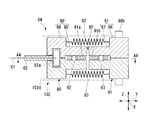
- the operation unit 100 includes an operation unit main body 101, a slider 102, and a breaking mechanism 64.
- the operation portion main body 101 is attached to the proximal end portion of the coil sheath 66.
- the slider 102 is provided so as to be slidable in the axial direction Y with respect to the operation unit main body 101 by being externally fitted to the operation unit main body 101.
- the breaking mechanism 64 is connected to the proximal end portion of the operation wire 62 and the slider 102.
- the operation portion main body 101 is formed in a rod shape extending in the axial direction Y, and a finger hook portion 101a is provided at the base end portion.
- a flat surface portion 101c is provided on the base end side of the finger rest portion 101a so that the operation portion 100 can be easily grasped with both hands (see FIG. 4).
- a slit 101 b extending in the axial direction Y is formed in the operation unit main body 101.
- the slider 102 is formed in a cylindrical shape.
- a recess 102 a is formed on the outer peripheral surface of the slider 102 over the entire periphery.
- a pair of flange portions 102 b and 102 c are formed such that a recess 102 a is positioned between the pair of flange portions 102 b and 102 c in the axial direction Y.
- the pair of flange portions 102b and 102c are elliptical when viewed in the axial direction Y (see FIGS. 4 and 8). As a result, the slider 102 can be easily gripped, and space can be saved when the operation unit 100 of the endoscope treatment tool 1 is packed. As shown in FIG.
- a groove 102 e extending in the orthogonal direction Z is formed in the cylindrical hole 102 d of the slider 102. Since the slider 102 is engaged with the slit 101 b of the operation unit main body 101, the movement range in the axial direction Y of the slider 102 with respect to the operation unit main body 101 is restricted.
- the breaking mechanism 64 is disposed in the cylindrical hole 102 d of the slider 102.
- the breaking mechanism 64 is built in the operation unit 100.
- the breaking mechanism 64 includes a first support member 80, a second support member 81, a planned fracture member 82, and an elastic member 83.
- the first support member 80 is connected to the proximal end portion of the operation wire 62.
- the second support member 81 is disposed on the proximal end side of the first support member 80.
- the planned fracture member 82 and the elastic member 83 are connected to the first support member 80 and the second support member 81.
- the breaking mechanism 64 includes a pair of a first support member 80, a second support member 81, and an elastic member 83.
- the pair of first support members 80, the pair of second support members 81, and the pair of elastic members 83 are arranged so as to be line-symmetric with respect to the axis C1 in a plan view shown in FIG.
- the first support member 80 includes a support portion body 85 and a wall portion 86.
- the support portion main body 85 is formed in a plate shape extending in the axial direction Y.
- the wall portion 86 is erected in a direction orthogonal to the distal end portion of the support body 85 and away from the axis C1.
- a groove 85 a extending in the orthogonal direction Z is formed at the tip of the surface on the axis C ⁇ b> 1 side of the support body 85.
- An accommodating portion 85b is formed at the base end portion of the surface on the axis C1 side of the support portion main body 85.
- the first support member 80 is formed of a material such as resin.
- the wire fixing portion 62 a is fixed to the proximal end portion of the operation wire 62 and has a larger diameter than the operation wire 62.
- the wire fixing portion 62a is formed integrally with the operation wire 62, and is engaged with the groove 85a of each first support member 80 so as to be sandwiched from both sides. Thereby, each first support member 80 is connected to the proximal end portion of the operation wire 62.
- the second support member 81 is disposed so as to face the first support member 80 in a plane orthogonal to the axial direction Y.
- the second support member 81 has a support portion main body 87 and a wall portion 88.
- the support portion main body 87 is formed in a plate shape extending in the axial direction Y.
- the wall portion 88 is erected in the direction orthogonal to the base end portion of the support portion main body 87 and away from the axis C1.
- An accommodating portion 87a is formed at the tip of the surface on the axis C1 side of the support portion main body 87.
- a protrusion 88b is formed on the tip surface in the standing direction (direction away from the axis C1) where the wall portion 88 is erected.
- the protrusion 88 b engages with the groove 102 e of the slider 102.
- the proximal end face 86a of the wall portion 86 and the distal end face 88a of the wall portion 88 are opposed to each other in the axial direction Y.
- the planned fracture member 82 is formed in a plate shape with a metal such as stainless steel.
- the planned fracture member 82 has a first end portion 89, a second end portion 90, and a central fracture portion 91.
- the first end 89 is connected to the support body 85 of the first support member 80.
- the second end 90 is connected to the support body 87 of the second support member 81.
- the central fracture portion 91 is disposed between the first end portion 89 and the second end portion 90.
- the planned fracture member 82 is configured such that the width of the central fracture portion 91 is narrower than the width of the first end portion 89 and the width of the second end portion 90.
- a through hole 89 a is formed in the first end portion 89.
- the first end portion 89 is connected to the first support member 80 by inserting the pin 92 provided in the housing portion 85 b of the support portion main body 85 into the through hole 89 a.
- a through hole 90 a is formed in the second end 90.
- the second end 90 is connected to the second support member 81 by inserting a pin 93 provided in the housing portion 87 a of the support portion main body 87 into the through hole 90 a. Gaps are formed between the pin 92 and the through-hole 89a and between the pin 93 and the through-hole 90a.
- the base end surface of the support portion main body 85 is pushed out to the front end side by the front end surface of the support portion main body 87. be able to. For this reason, it can suppress that a load acts on the fracture
- the tensile strength against the force pulling in the axial direction Y is lower in the central fracture portion 91 than in the first end portion 89 and the second end portion 90.
- the fracture-scheduled member 82 can be integrally formed by pressing a metal plate.
- the planned fracture member 82 is weaker at the central fracture portion 91 than the first support member 80 and the second support member 81.
- the planned fracture member 82 fractures with a low tensile strength in the axial direction Y.
- the tensile strength at which the rupture-scheduled member 82 breaks is higher (larger) than the force necessary to move the clip body 11 accommodated in the holding tube 31 to the proximal end side with respect to the holding tube 31 to be in the locked state. .
- the tensile strength at which the planned fracture member 82 breaks is lower than the tensile strength of the clip main body 11, the connecting member 63, the loop portion 73, the enlarged diameter portion 72, and the operation wire 62.
- the tensile strength at which the rupture-scheduled member 82 is ruptured is the clip body 11 and the connection member 63, the connection member 63 and the loop portion 73, the loop portion 73 and the enlarged diameter portion 72, and the enlarged diameter portion 72 and the operation wire 62. Lower than connection strength.
- the tensile strength at which the rupture-scheduled member 82 breaks will be described with specific numerical values. As will be described later, when the amount of force (force) F1 required to get over the clip 10 is about 20 to 50 N, the fracture-scheduled member 82 is determined in consideration of the frictional force in the insertion portion 60 and the like. The breaking strength is set to about 100N.
- the elastic member 83 is constituted by a helical spring.
- the end portions of the elastic member 83 are connected to the base end surface 86a of the wall portion 86 and the distal end surface 88a of the wall portion 88, respectively.
- the elastic member 83 is elastically deformed without being plastically deformed even when it is pulled in the axial direction Y with the tensile strength at which the member 82 to be broken is broken. Since these support members 80 and 81 are disposed in the cylindrical hole 102 d of the slider 102, the support members 80 and 81 are restricted so as to move only in the axial direction Y with respect to the slider 102.
- the second support member 81 By engaging the protrusion 88 b of the second support member 81 with the groove 102 e of the slider 102, the second support member 81 is connected to the slider 102, and the second support member 81 is integrated with the slider 102 and the operation unit main body 101. Slide in the axial direction Y.
- the first support member 80 is connected to the second support member 81 via the fracture-scheduled member 82 and the elastic member 83.
- the first support member 80, the second support member 81, and the fracture-scheduled member 82 can move integrally to the proximal end side. That is, when the second support member 81 is pulled toward the base end side, the fracture-scheduled member 82 moves toward the base end side, and accordingly, the first support member 80 moves toward the base end side. Since the first support member 80 is connected to the operation wire 62, when the second support member 81 is pulled toward the proximal end, the operation wire 62 can be pulled toward the proximal end.
- the clip body 11 is pulled back with respect to the holding tube 31, the clip 10 is sequentially closed, and finally the locking portion 32 and the first locked portions 16, 17.
- the second locked portions 21 and 22 can be locked.
- the outer diameters of the pins 92 and 93 of the first support member 80 and the second support member 81 are slightly smaller than the inner diameters of the through holes 89a and 90a of the member 82 to be broken. Therefore, a gap is formed between the outer diameters of the pins 92 and 93 and the inner diameters of the through holes 89a and 90a.
- the gap provided between the first support member 80 and the second support member 81 is configured to be smaller than the gap. Therefore, even if the second support member 81 is moved to the distal end side, the fracture-scheduled member 82 is not immediately moved to the distal end side, and the fracture-scheduled member 82 is configured not to generate a compressive force in the axial direction Y. .
- transforming does not arise.
- the tip end surface of the enlarged diameter portion 72 is in contact with the stepped portion 68, and the loop portion 73 protrudes up to the maximum protruding amount with respect to the tip member 67. Since the connecting member 63 is disposed in the holding tube 31, the connecting member 63 cannot rotate with respect to the loop portion 73, and the engagement between the hook portion 77 and the central portion 14 is maintained. At this time, the planned fracture member 82 of the fracture mechanism 64 is not broken.
- FIG. 12 is a schematic diagram showing the amount of force necessary to pull back the slider with respect to the amount of movement to pull back the slider in the endoscope treatment tool.
- the slider 102 is moved to the proximal end side (retracted) with respect to the operation unit main body 101.
- the clip 10 is configured such that the amount of force required to pull back the slider 102 changes according to this movement.
- FIG. 12 also shows the relative change in the amount of force required to pull back the slider in various states such as the initial state of the clip 10. As the slider 102 is pulled back, the clip 10 changes from the initial state to the contact state, the ride-over state, and the locking state. Details of the change in the force and the change in the state of the clip 10 will be described in detail.
- the enlarged diameter portion 72 contacts the stepped portion 68.
- the proximal end surface of the pressing tube 31 is in contact with the distal end support surface 67b, and the pressing tube 31 and the distal end support surface 67b are not separated from each other beyond at least the depth in the longitudinal direction of the support member 69.
- the clip 10 is made to face the target tissue T in the body, for example, by bending the bending portion provided in the endoscope insertion portion.
- the arm portions 12 and 13 are pressed against the target tissue T by pressing the endoscope treatment tool 1 against the endoscope.
- the first arm portion 12 and the second arm portion 13 are urged toward the inner peripheral surface of the distal end portion of the presser tube 31.
- the first arm portion 12 is elastically deformed to the second arm portion 13 side and the second arm portion 13 is elastically deformed to the first arm portion 12 side.
- the arm parts 12 and 13 close).
- the helical spring 36 is compressed in the axial direction Y.
- the amount of force that pulls back the slider 102 is transmitted to the fracture-scheduled member 82 via the second support member 81. Since there is only a small gap between the pin 92 and the through-hole 89a and between the pin 93 and the through-hole 90a, the amount of force for pulling back the slider 102 is received not by the elastic member 83 but by the member to be broken.
- the connecting member 63 Since the connecting member 63 is disposed in the holding tube 31 or the sheath portion 61, the connecting member 63 cannot rotate with respect to the loop portion 73, and the engagement between the hook portion 77 and the central portion 14 is maintained. . Since the planned fracture member 82 of the fracture mechanism 64 is not broken, the amount of force for pulling back the slider 102 is transmitted to the operation wire 62 via the planned fracture member 82. When the slider 102 is pushed in, the base end surface of the support portion main body 85 is pushed to the tip end side by the tip end surface of the support portion main body 87 of the breaking mechanism 64, so that the amount of force for pushing the slider 102 is transmitted to the operation wire 62. It is done.
- the first locked portions 16 and 17 are in contact with the locking portion 32 while the first locked portions 16 and 17 are in contact with each other.
- the edge 32a of the part 32 moves from the position P1 to the position P3.
- the edge portion 32a of the locking portion 32 with which the first locked portion 17 contacts moves from the position P2 to the position P4.
- the distal end portion of the proximal end surface 16a of the first locked portion 16 and the distal end portion of the proximal end surface 17a of the first locked portion 17 are the edge portion 32a of the locking portion 32.
- the state of overcoming in contact with is shown.
- the second arm portion 13 receives a vertical drag from the edge portion 32 a of the locking portion 32 and moves in the facing direction X so as to approach the first arm portion 12.
- the central portion 14 is elastically deformed so that both end portions thereof move to the axis C1 side.
- the rate of increase in the amount of force necessary for pulling back the slider 102 per unit moving amount for pulling back the slider 102 is larger than in the region R1 described above.
- the region R1 shows a relatively gentle change in the force characteristic
- the first locked portions 16 and 17 and the second locked portions 21 and 22 are in contact with the locking portion 32.
- R2 indicates a change in the force characteristic with a relatively steep gradient. That is, for the user who pulls back the slider 102, when the slider 102 is pulled back in the region R2 compared to the region R1, the slider 102 feels sharply heavy. Thereby, the user can easily recognize whether the state in which the slider 102 is currently pulled back is the region R1 or the region R2, in other words, whether the slider 102 is pulled back beyond the contact state.
- the clip 10 is kept closed. Since the connecting member 63 is disposed in the sheath portion 61, the engagement between the hook portion 77 and the central portion 14 is maintained. The member to be broken 82 of the breaking mechanism 64 is not broken.
- the amount of force F1 required to bring the clip 10 shown in FIG. 12 into the override state is, for example, about 20 to 50 N (Newton).
- the distance between the position P3 and the position P4 of the edge portion 32a is equal to the length L1 of the first locked portions 16 and 17 described above.
- the clip 10 is elastically deformed. For this reason, if the slider 102 is pushed in when the clip 10 is in one of the regions R1 and R2, the helical spring 36 that has been compressed is extended.
- the clip main body 11 moves to the distal end side with respect to the holding tube 31 in a state where the holding tube 31 is in contact with the distal end support surface 67b, and the clip 10 is in the initial state shown in FIG.
- the endoscope such as bending the bending portion
- the clip 10 is made to face another target tissue T again. Thereafter, the target tissue T can be re-gripped with the clip 10 by performing the above-described procedure.
- the orientation of the clip 10 can be adjusted by rotating the operation wire 62 relative to the sheath portion 61 in the initial state. At this time, it is conceivable that the clip body 11 rotates around the axis C ⁇ b> 1 with respect to the holding tube 31. However, since the edge portion 32a of the locking portion 32 is formed in a circular shape coaxial with the pressing tube 31, the locking portion 32, the first locked portions 16, 17 and the second locked portions 21, 22 are formed. The locking by and is kept well.
- the proximal end side of the first arm portion 12 and the proximal end side of the second arm portion 13 are moved in the facing direction X so as to be separated from each other.
- the distal end surfaces 16 b and 17 b of the first locked portions 16 and 17 become the proximal end surface 32 b of the locking portion 32. It will be in the latching state latched by the front end side with respect to.
- the strands 36 a of the helical spring 36 compressed in the axial direction Y are almost in close contact with the adjacent strands 36 a in the axial direction Y. It becomes a tightly wound state.
- the distal end surfaces 16b and 17b of the first locked portions 16 and 17 are locked to the proximal end surface 32b of the locking portion 32. Movement is restricted. That is, the clip 10 is maintained in a state in which the target tissue T is ligated, and cannot return to the initial state in which the arms 12 and 13 are opened.
- the clip 10 is fixed with the arms 12 and 13 closed.
- the central portion 14 protrudes closer to the base end side than the presser tube 31.
- first locked portions 16 and 17 and the second locked portions 21 and 22 move to the proximal end side beyond the locking portion 32, the first locked portions 16 and 17 and the second locked portions
- the stop portions 21 and 22 may get over the lock portion 32 by scraping the lock portion 32 or deforming the lock portion 32. In such a case, chamfering is performed on portions of the first locked portions 16 and 17 and the second locked portions 21 and 22 in contact with the locking portions 32 in order to prevent excessive locking of the locking portions 32. Etc. are preferable.
- a region R4 shown in FIG. 12 corresponds to the state from the locked state to the front of the fracture state of the fracture mechanism 64 described later. In the region R4 shown in FIG. 12, the clip 10 is kept closed. Since the connecting member 63 is disposed in the sheath portion 61, the engagement between the hook portion 77 and the central portion 14 is maintained. The member to be broken 82 of the breaking mechanism 64 is not broken.
- the elastic member 83 since the first support member 80 and the second support member 81 are connected by the elastic member 83, the movement toward the tip side is restricted. The clip 10 is not detached from the support member 69. After the fracture-scheduled member 82 is broken, the connection state between the first support member 80 and the second support member 81 is maintained by the elastic member 83.
- the impact of breaking the central breaking portion 91 is transmitted to the user who holds the operation portion 100. That is, the breaking mechanism 64 causes the user to recognize that the clip 10 has been fixed in the closed state by breaking the member to be broken 82. By providing the breaking mechanism 64 in the operation unit 100, the user can recognize this impact more reliably. By recognizing the transmitted impact, the user knows that the clip 10 is in the locked state and the target tissue T is ligated. The user can also recognize that the clip 10 is in the locked state by further pulling back the slider 102 and bringing the slider 102 into contact with the proximal end portion of the slit 101 b of the operation unit main body 101.
- Region R5 shown in FIG. 12 includes a broken state and a state in which slider 102 is pulled back from the broken state.
- the elastic member 83 extends after the fracture-desired member 82 is broken, so that the amount of force necessary to pull the slider 102 is temporarily reduced as the slider 102 is pulled back. It will increase later.
- the clip 10 is kept closed. Since the connecting member 63 is disposed in the sheath portion 61, the engagement between the hook portion 77 and the central portion 14 is maintained. The planned fracture member 82 of the fracture mechanism 64 is broken.
- the procedure for separating the clip 10 from the treatment instrument main body 40 is specifically as follows.
- the slider 102 is pushed in, as shown in FIG. 23, the proximal end surface of the first support member 80 is pushed out to the distal end surface of the second support member 81, and the operation wire 62 moves to the distal end side with respect to the coil sheath 66.
- the distal end surface of the enlarged diameter portion 72 comes into contact with the stepped portion 68, and the loop portion 73 projects from the distal end member 67 to a length L 2 that is the maximum projecting amount.
- the connecting member 63 protrudes further to the distal end side than the distal end member 67, the clip body 11 and the holding tube 31 move integrally to the distal end side. Since the connecting member 63 is located outside the holding tube 31, the connecting member 63 can rotate with respect to the loop portion 73.
- the inclined surface 76b of the connecting member 63 comes into contact with the proximal end surface of the central portion 14 of the clip 10 ligating the target tissue T.
- the hook portion 77 is rotated in the direction D together with the connecting portion main body 76 while being guided by the inclined surface 76b, and the engagement between the hook portion 77 and the central portion 14 is released.
- the clip 10 which ligated the target tissue T is detained in the body. That is, in the state where the slider 102 is pushed in from the state of the region R5 and the connecting member 63 protrudes further to the tip side than the tip member 67 as shown in FIG. The engagement between the hook portion 77 and the central portion 14 can be released. The planned fracture member 82 of the fracture mechanism 64 is broken.
- the clip main body 11 When the clip main body 11 is further moved to the proximal end side from this contact state, the first locked portions 16 and 17 and the second locked portions 21 and 22 are in point contact with the locking portion 32 and receive a vertical drag. . As a result, the arms 12 and 13 are elastically deformed in the facing direction X so as to approach each other. As shown in FIGS. 29 to 31, the first locked portions 16 and 17 and the second locked portions 21 and 22 are inserted into the locking portion 32. In this riding over state, the arm portions 12 and 13 are kept closed. When the clip body 11 is further moved to the proximal end side from this over-ride state, the first locked portions 16 and 17 and the second locked portions 21 and 22 move to the proximal end side beyond the locking portion 32. .
- the arms 12 and 13 are elastically deformed in the facing direction X so as to be separated from each other by their own elastic force. Thereby, as shown in FIGS. 32 to 34, the first locked portions 16, 17 and the second locked portions 21, 22 are locked to the locking portion 32 on the distal end side. . In this locked state, the arms 12 and 13 are kept closed, and the clip 10 cannot return to the state from the initial state to the overcoming state.
- the helical springs 36 that are respectively locked to the protrusions 18, 19, 23, 24 of the clip body 11 and the locking part 32 of the presser tube 31 are arranged in the axial direction Y. Compressed.
- the state in which the target tissue T is ligated by the arm portions 12 and 13 can be maintained.
- the clip body 11 is operated to be pushed out in the distal direction of the operation wire 62 with respect to the holding tube 31 and moved to the tip side. Then, the helical spring 36 compressed in the axial direction Y extends.
- the clip 10 is returned to the initial state by moving the clip body 11 toward the distal end side with respect to the pressing tube 31 in a state where the pressing tube 31 is in contact with the distal end support surface 67b.
- the target tissue T can be re-gripped with the clip 10.
- the state of the clip 10 is divided into a region R1 and a region R2 that can return to the initial state again even when the arms 12 and 13 are closed, and a region R3 that cannot return to the initial state again.
- the locking portion 32, the first locked portions 16, 17 and the second locked portions 21, 22 are provided, and the amount of movement for pulling back the slider 102 is set. The change in the force necessary to pull back the slider 102 is changed.
- the second arm portion 13 is provided with second locked portions 21 and 22. These second locked portions 21 and 22 are arranged side by side with the first locked portions 16 and 17 in the facing direction X. Thereby, the force which latches to the latching
- the first locked portions 16 and 17 protrude in the orthogonal direction Z.
- the first locked portions 16 and 17 can be formed easily and at a reduced manufacturing cost.
- the base end surface 16a of the first locked portion 16 is inclined so as to be separated from the first arm portion 12 toward the distal end side.
- the distal end surface 16 b of the first locked portion 16 and the base end surface 32 b of the locking portion 32 are orthogonal to the axial direction Y. Therefore, when the first arm portion 12 is moved to the proximal end side with respect to the holding tube 31, the first arm portion 12 can be guided so as to approach the second arm portion 13 smoothly.
- the first locking portion 32 is moved to the first position.
- the locked portion 16 can be reliably locked to the distal end side.
- the first locked portions 16 and 17 provided on the first arm portion 12 and the second locked portions 21 and 22 provided on the second arm portion 13 protrude in the orthogonal direction Z. It is a configuration.
- the orthogonal direction Z is a direction away from the second arm portion 13.
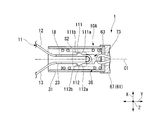
- the locked portion 111 is protruded from the side surface of the first arm portion 12 in a direction away from the second arm portion 13 in the facing direction X. It may be provided.
- the locked portion 111 protrudes in a direction away from the second arm portion 13 on the reference surface S2 parallel to the axis C1 of the pressing tube 31. As shown in FIG.
- the proximal end surface 111a of the locked portion 111 is inclined so as to be separated from the first arm portion 12 toward the distal end side. ing.
- the front end surface 111 b of the locked portion 111 is orthogonal to the axial direction Y.
- the locked portion 112 is provided so as to protrude from the side surface of the second arm portion 13 in a direction away from the first arm portion 12 in the facing direction X.
- the proximal end surface 112a and the distal end surface 112b of the locked portion 112 are symmetrical with respect to the proximal end surface 111a and the distal end surface 111b of the locked portion 111 and the axis C1. Each is formed to be. Even if the locked portions 111 and 112 are configured in this way, the same effects as in the above embodiment can be obtained.
- the presser tube 31 is formed in a cylindrical shape, that is, the cross section perpendicular to the axis C1 of the presser tube 31 has a circular contour shape.
- the cross section of the holding tube is not limited to this, and may be an outline shape such as an ellipse or a polygon.
- the second locked portions 21 and 22 may not be formed on the second arm portion 13.
- first locked portions 16 and 17 are formed on the first arm portion 12, the first arm portion 12 can be locked to the distal end side with respect to the locking portion 32.
- first locked portion 17 may not be formed on the first arm portion 12 but only the first locked portion 16 may be formed.
- the clip 10 may not include the helical spring 36.
- the helical spring 36 is configured to push out the clip body 11 with the holding tube 31 as a base point.
- FIG. Protrusions 18 and 19 are provided on the first arm 12, and protrusions 23 and 24 are provided on the second arm 13.
- the protrusions may be provided only on one of the first arm part 12 and the second arm part 13, or the number of protrusions provided on one arm part may be one.
- the protrusions 18 and 19 project in the orthogonal direction Z, it is only necessary to project in the direction intersecting the axial direction Y. This is because even with this configuration, the tip of the helical spring 36 can be locked by the protrusion.
- the distal end surface 16 b of the first locked portion 16 and the proximal end surface 32 b of the locking portion 32 are orthogonal to the axial direction Y.
- the distal end surface 16b may be inclined so as to be separated from the first arm portion 12 toward the distal end side.
- the base end face 32b may be inclined so as to approach the axis C1 of the presser tube 31 toward the base end side.
- the edge portion 32 a of the locking portion 32 is formed in a circular shape coaxial with the pressing tube 31.
- the shape of the edge portion 32a may be a contour shape such as an ellipse or a polygon.
- the clip spring 11 cannot move to the proximal end side with respect to the holding tube 31 because the helical spring 36 is in a tightly wound state when the clip 10 is locked.
- the protrusions provided on the arm portions 12 and 13 are engaged with the locking portions 32, so that the clip body 11 is proximal to the presser tube 31. You may make it impossible to move to the side.
- a protective cap 120 may be provided that is detachably attached to the distal end portion of the outer tube 50 of the endoscope treatment tool 1 when provided to the user.
- the protective cap 120 is formed in a tubular shape, and a contact portion 121 having a reduced inner diameter is formed at the tip.
- Clip unit 11 Clip main body 12 1st arm part 13 2nd arm part 16,17 1st to-be-latched part 21,22 2nd to-be-latched part 31 Holding pipe 32 Locking part 32b Base end surface (base end side end surface) 32c Tip surface (tip side end surface) 40 Treatment tool body
Abstract
L'unité de pince de l'invention est équipée : d'un corps principal de pince qui possède une première partie bras, une seconde partie bras, et une partie centrale positionnée entre une partie extrémité de base de la première partie bras et une partie extrémité de base de la seconde partie bras ; d'un tube de pression qui prend une forme cylindrique permettant de loger ledit corps principal de pince, et qui déforme ledit corps principal de pince selon les déplacements côté extrémité de base de ladite partie centrale, de ladite première partie bras et de ladite seconde partie bras, rapprochant ainsi les parties extrémité de base desdites première et seconde parties bras ; d'une partie verrouillage en saillie par rapport à une face périphérique interne dudit tube de pression côté extrémité de base ; et d'une première partie à verrouiller qui est en saillie par rapport à une face latérale de ladite première partie bras, et qui tout en étant capable d'avancer par rapport audit tube de pression dans un état de positionnement côté extrémité avant par rapport à ladite partie verrouillage à l'intérieur dudit tube de pression, est régulée dans son avancée par rapport audit tube de pression par verrouillage avec ladite partie verrouillage dans un état de déplacement côté extrémité de base par rapport à ladite partie verrouillage et au-delà de cette dernière.
Priority Applications (5)
| Application Number | Priority Date | Filing Date | Title |
|---|---|---|---|
| EP14795099.2A EP2995264B1 (fr) | 2013-05-07 | 2014-04-22 | Unité de pince |
| CN201480003669.4A CN104936537B (zh) | 2013-05-07 | 2014-04-22 | 夹具单元 |
| JP2014556847A JP5750619B2 (ja) | 2013-05-07 | 2014-04-22 | クリップユニット |
| US14/476,132 US9949740B2 (en) | 2013-05-07 | 2014-09-03 | Clip unit |
| US15/916,754 US10842500B2 (en) | 2013-05-07 | 2018-03-09 | Clip unit |
Applications Claiming Priority (2)
| Application Number | Priority Date | Filing Date | Title |
|---|---|---|---|
| US201361820219P | 2013-05-07 | 2013-05-07 | |
| US61/820,219 | 2013-05-07 |
Related Child Applications (1)
| Application Number | Title | Priority Date | Filing Date |
|---|---|---|---|
| US14/476,132 Continuation US9949740B2 (en) | 2013-05-07 | 2014-09-03 | Clip unit |
Publications (1)
| Publication Number | Publication Date |
|---|---|
| WO2014181675A1 true WO2014181675A1 (fr) | 2014-11-13 |
Family
ID=51867157
Family Applications (1)
| Application Number | Title | Priority Date | Filing Date |
|---|---|---|---|
| PCT/JP2014/061231 WO2014181675A1 (fr) | 2013-05-07 | 2014-04-22 | Unité de pince |
Country Status (5)
| Country | Link |
|---|---|
| US (2) | US9949740B2 (fr) |
| EP (1) | EP2995264B1 (fr) |
| JP (1) | JP5750619B2 (fr) |
| CN (1) | CN104936537B (fr) |
| WO (1) | WO2014181675A1 (fr) |
Cited By (2)
| Publication number | Priority date | Publication date | Assignee | Title |
|---|---|---|---|---|
| WO2018011846A1 (fr) * | 2016-07-11 | 2018-01-18 | オリンパス株式会社 | Instrument de traitement endoscopique |
| WO2018173474A1 (fr) * | 2017-03-22 | 2018-09-27 | 富士フイルム株式会社 | Outil d'agrafage chirurgical |
Families Citing this family (11)
| Publication number | Priority date | Publication date | Assignee | Title |
|---|---|---|---|---|
| WO2017163328A1 (fr) | 2016-03-23 | 2017-09-28 | Ykk株式会社 | Outil de fixation de matériau de peau |
| CA3028007C (fr) * | 2016-09-20 | 2021-01-26 | Boston Scientific Scimed, Inc. | Applicateur rechargeable pour clips hemostatiques |
| JP6858258B2 (ja) | 2017-06-21 | 2021-04-14 | 富士フイルム株式会社 | クリップ処置具 |
| WO2018235401A1 (fr) * | 2017-06-21 | 2018-12-27 | 富士フイルム株式会社 | Instrument médical à pince |
| WO2018235402A1 (fr) | 2017-06-21 | 2018-12-27 | 富士フイルム株式会社 | Instrument médical à pince |
| WO2019189864A1 (fr) * | 2018-03-30 | 2019-10-03 | 日本ゼオン株式会社 | Attache à demeure |
| CN113194849A (zh) * | 2018-12-11 | 2021-07-30 | 奥林巴斯株式会社 | 盒、夹具系统以及卡合方法 |
| CN113164176A (zh) * | 2018-12-11 | 2021-07-23 | 奥林巴斯株式会社 | 医疗设备 |
| JP2022066160A (ja) | 2020-10-16 | 2022-04-28 | オリンパスメディカルシステムズ株式会社 | 湾曲可能なクリップデバイス |
| US11937828B2 (en) * | 2021-01-26 | 2024-03-26 | Olympus Medical Systems Corp. | Endoscope treatment device |
| US11944321B2 (en) * | 2021-01-26 | 2024-04-02 | Olympus Medical Systems Corp. | Endoscopic treatment device |
Citations (9)
| Publication number | Priority date | Publication date | Assignee | Title |
|---|---|---|---|---|
| JPS62170010U (fr) * | 1986-04-18 | 1987-10-28 | ||
| JPH08280701A (ja) * | 1995-04-13 | 1996-10-29 | Olympus Optical Co Ltd | 結紮装置 |
| JP2002355249A (ja) * | 2001-05-31 | 2002-12-10 | Asahi Optical Co Ltd | 内視鏡用クリップ装置 |
| JP2004216058A (ja) * | 2003-01-17 | 2004-08-05 | Olympus Corp | 生体組織のクリップ装置 |
| JP2007097664A (ja) * | 2005-09-30 | 2007-04-19 | Sumitomo Bakelite Co Ltd | 内視鏡用クリップ |
| JP2010221059A (ja) | 2010-06-09 | 2010-10-07 | Olympus Corp | 結紮装置 |
| WO2010133215A1 (fr) * | 2009-05-22 | 2010-11-25 | Medi-Globe Gmbh | Dispositif d'application destiné à l'application, en particulier endoscopique, d'une agrafe médicale dans ou sur le corps d'un sujet |
| US20110054498A1 (en) * | 2008-05-05 | 2011-03-03 | Niti Surgical Solutions Ltd. | Endoscopic compression clip and system and method for use thereof |
| JP2012065834A (ja) * | 2010-09-22 | 2012-04-05 | Fujifilm Corp | 結紮装置及びこれに用いるクリップユニット |
Family Cites Families (15)
| Publication number | Priority date | Publication date | Assignee | Title |
|---|---|---|---|---|
| WO1996014020A1 (fr) | 1994-11-02 | 1996-05-17 | Olympus Optical Co. Ltd. | Instrument fonctionnant avec un endoscope |
| JP4472217B2 (ja) * | 2000-10-16 | 2010-06-02 | オリンパス株式会社 | 生体組織のクリップ装置 |
| JP4059656B2 (ja) | 2001-03-07 | 2008-03-12 | オリンパス株式会社 | 生体組織のクリップ装置 |
| JP4827304B2 (ja) * | 2001-03-14 | 2011-11-30 | オリンパス株式会社 | 生体組織のクリップ装置 |
| US6991634B2 (en) * | 2001-05-23 | 2006-01-31 | Pentax Corporation | Clip device of endoscope |
| JP4836353B2 (ja) | 2001-05-28 | 2011-12-14 | Hoya株式会社 | 内視鏡用クリップ装置 |
| US7727247B2 (en) * | 2002-08-21 | 2010-06-01 | Olympus Corporation | Living tissue ligation device |
| JP4502134B2 (ja) | 2003-03-17 | 2010-07-14 | 住友ベークライト株式会社 | クリップ及び生体組織のクリップ装置 |
| JP4758173B2 (ja) * | 2004-12-24 | 2011-08-24 | オリンパス株式会社 | 結紮装置 |
| JP4116049B2 (ja) * | 2006-07-25 | 2008-07-09 | オリンパスメディカルシステムズ株式会社 | 生体組織のクリップ装置 |
| WO2008090978A1 (fr) * | 2007-01-26 | 2008-07-31 | Olympus Medical Systems Corp. | Dispositif de maintien et outil de maintien |
| EP2098176A3 (fr) * | 2008-03-06 | 2009-10-07 | FUJIFILM Corporation | Dispositif de détourage de type chargeur |
| JP2010029629A (ja) * | 2008-06-30 | 2010-02-12 | Fujifilm Corp | クリップ処置具 |
| JP5588711B2 (ja) * | 2010-03-30 | 2014-09-10 | 富士フイルム株式会社 | 結紮装置 |
| JP2012065835A (ja) * | 2010-09-22 | 2012-04-05 | Fujifilm Corp | 結紮装置及びこれに用いるクリップユニット |
-
2014
- 2014-04-22 WO PCT/JP2014/061231 patent/WO2014181675A1/fr active Application Filing
- 2014-04-22 JP JP2014556847A patent/JP5750619B2/ja active Active
- 2014-04-22 CN CN201480003669.4A patent/CN104936537B/zh active Active
- 2014-04-22 EP EP14795099.2A patent/EP2995264B1/fr active Active
- 2014-09-03 US US14/476,132 patent/US9949740B2/en active Active
-
2018
- 2018-03-09 US US15/916,754 patent/US10842500B2/en active Active
Patent Citations (9)
| Publication number | Priority date | Publication date | Assignee | Title |
|---|---|---|---|---|
| JPS62170010U (fr) * | 1986-04-18 | 1987-10-28 | ||
| JPH08280701A (ja) * | 1995-04-13 | 1996-10-29 | Olympus Optical Co Ltd | 結紮装置 |
| JP2002355249A (ja) * | 2001-05-31 | 2002-12-10 | Asahi Optical Co Ltd | 内視鏡用クリップ装置 |
| JP2004216058A (ja) * | 2003-01-17 | 2004-08-05 | Olympus Corp | 生体組織のクリップ装置 |
| JP2007097664A (ja) * | 2005-09-30 | 2007-04-19 | Sumitomo Bakelite Co Ltd | 内視鏡用クリップ |
| US20110054498A1 (en) * | 2008-05-05 | 2011-03-03 | Niti Surgical Solutions Ltd. | Endoscopic compression clip and system and method for use thereof |
| WO2010133215A1 (fr) * | 2009-05-22 | 2010-11-25 | Medi-Globe Gmbh | Dispositif d'application destiné à l'application, en particulier endoscopique, d'une agrafe médicale dans ou sur le corps d'un sujet |
| JP2010221059A (ja) | 2010-06-09 | 2010-10-07 | Olympus Corp | 結紮装置 |
| JP2012065834A (ja) * | 2010-09-22 | 2012-04-05 | Fujifilm Corp | 結紮装置及びこれに用いるクリップユニット |
Non-Patent Citations (1)
| Title |
|---|
| See also references of EP2995264A4 |
Cited By (7)
| Publication number | Priority date | Publication date | Assignee | Title |
|---|---|---|---|---|
| WO2018011846A1 (fr) * | 2016-07-11 | 2018-01-18 | オリンパス株式会社 | Instrument de traitement endoscopique |
| US11020126B2 (en) | 2016-07-11 | 2021-06-01 | Olympus Corporation | Endoscopic surgical device |
| WO2018173474A1 (fr) * | 2017-03-22 | 2018-09-27 | 富士フイルム株式会社 | Outil d'agrafage chirurgical |
| CN110461254A (zh) * | 2017-03-22 | 2019-11-15 | 富士胶片株式会社 | 夹具处置器具 |
| JPWO2018173474A1 (ja) * | 2017-03-22 | 2019-12-26 | 富士フイルム株式会社 | クリップ処置具 |
| US11141166B2 (en) | 2017-03-22 | 2021-10-12 | Fujifilm Corporation | Clip treatment tool |
| CN110461254B (zh) * | 2017-03-22 | 2022-09-16 | 富士胶片株式会社 | 夹具处置器具 |
Also Published As
| Publication number | Publication date |
|---|---|
| CN104936537A (zh) | 2015-09-23 |
| US20180193022A1 (en) | 2018-07-12 |
| JP5750619B2 (ja) | 2015-07-22 |
| US9949740B2 (en) | 2018-04-24 |
| EP2995264A1 (fr) | 2016-03-16 |
| EP2995264B1 (fr) | 2018-03-21 |
| US20150230799A1 (en) | 2015-08-20 |
| CN104936537B (zh) | 2017-03-15 |
| JPWO2014181675A1 (ja) | 2017-02-23 |
| US10842500B2 (en) | 2020-11-24 |
| EP2995264A4 (fr) | 2016-12-21 |
Similar Documents
| Publication | Publication Date | Title |
|---|---|---|
| JP5750620B2 (ja) | 内視鏡処置具 | |
| JP5750619B2 (ja) | クリップユニット | |
| JP5750624B2 (ja) | 内視鏡処置具 | |
| US20210267602A1 (en) | Endoscope clip and operation method for clip arm | |
| US10842351B2 (en) | Endoscope treatment tool | |
| JP7209012B2 (ja) | クリップユニットおよび内視鏡クリップ | |
| JP2007136128A (ja) | 内視鏡用クリップ装置 | |
| EP3643254B1 (fr) | Instrument médical à pince | |
| US20210290240A1 (en) | Medical device and method of releasing clip unit | |
| JPWO2018235404A1 (ja) | クリップ処置具 | |
| US10905435B2 (en) | Endoscope treatment tool | |
| WO2022163680A1 (fr) | Dispositif pince et dispositif de traitement endoscope |
Legal Events
| Date | Code | Title | Description |
|---|---|---|---|
| ENP | Entry into the national phase |
Ref document number: 2014556847 Country of ref document: JP Kind code of ref document: A |
|
| 121 | Ep: the epo has been informed by wipo that ep was designated in this application |
Ref document number: 14795099 Country of ref document: EP Kind code of ref document: A1 |
|
| NENP | Non-entry into the national phase |
Ref country code: DE |
|
| WWE | Wipo information: entry into national phase |
Ref document number: 2014795099 Country of ref document: EP |