WO2014175272A1 - エンジン - Google Patents
エンジン Download PDFInfo
- Publication number
- WO2014175272A1 WO2014175272A1 PCT/JP2014/061299 JP2014061299W WO2014175272A1 WO 2014175272 A1 WO2014175272 A1 WO 2014175272A1 JP 2014061299 W JP2014061299 W JP 2014061299W WO 2014175272 A1 WO2014175272 A1 WO 2014175272A1
- Authority
- WO
- WIPO (PCT)
- Prior art keywords
- pressure
- rail
- engine
- rail pressure
- fuel
- Prior art date
- Legal status (The legal status is an assumption and is not a legal conclusion. Google has not performed a legal analysis and makes no representation as to the accuracy of the status listed.)
- Ceased
Links
Images




Classifications
-
- F—MECHANICAL ENGINEERING; LIGHTING; HEATING; WEAPONS; BLASTING
- F02—COMBUSTION ENGINES; HOT-GAS OR COMBUSTION-PRODUCT ENGINE PLANTS
- F02D—CONTROLLING COMBUSTION ENGINES
- F02D41/00—Electrical control of supply of combustible mixture or its constituents
- F02D41/30—Controlling fuel injection
- F02D41/38—Controlling fuel injection of the high pressure type
- F02D41/3809—Common rail control systems
- F02D41/3836—Controlling the fuel pressure
- F02D41/3845—Controlling the fuel pressure by controlling the flow into the common rail, e.g. the amount of fuel pumped
-
- F—MECHANICAL ENGINEERING; LIGHTING; HEATING; WEAPONS; BLASTING
- F02—COMBUSTION ENGINES; HOT-GAS OR COMBUSTION-PRODUCT ENGINE PLANTS
- F02D—CONTROLLING COMBUSTION ENGINES
- F02D41/00—Electrical control of supply of combustible mixture or its constituents
- F02D41/30—Controlling fuel injection
- F02D41/38—Controlling fuel injection of the high pressure type
- F02D41/3809—Common rail control systems
- F02D41/3836—Controlling the fuel pressure
-
- F—MECHANICAL ENGINEERING; LIGHTING; HEATING; WEAPONS; BLASTING
- F02—COMBUSTION ENGINES; HOT-GAS OR COMBUSTION-PRODUCT ENGINE PLANTS
- F02M—SUPPLYING COMBUSTION ENGINES IN GENERAL WITH COMBUSTIBLE MIXTURES OR CONSTITUENTS THEREOF
- F02M63/00—Other fuel-injection apparatus having pertinent characteristics not provided for in groups F02M39/00 - F02M57/00 or F02M67/00; Details, component parts, or accessories of fuel-injection apparatus, not provided for in, or of interest apart from, the apparatus of groups F02M39/00 - F02M61/00 or F02M67/00; Combination of fuel pump with other devices, e.g. lubricating oil pump
- F02M63/02—Fuel-injection apparatus having several injectors fed by a common pumping element, or having several pumping elements feeding a common injector; Fuel-injection apparatus having provisions for cutting-out pumps, pumping elements, or injectors; Fuel-injection apparatus having provisions for variably interconnecting pumping elements and injectors alternatively
- F02M63/0225—Fuel-injection apparatus having a common rail feeding several injectors ; Means for varying pressure in common rails; Pumps feeding common rails
-
- F—MECHANICAL ENGINEERING; LIGHTING; HEATING; WEAPONS; BLASTING
- F02—COMBUSTION ENGINES; HOT-GAS OR COMBUSTION-PRODUCT ENGINE PLANTS
- F02D—CONTROLLING COMBUSTION ENGINES
- F02D2200/00—Input parameters for engine control
- F02D2200/02—Input parameters for engine control the parameters being related to the engine
- F02D2200/06—Fuel or fuel supply system parameters
- F02D2200/0602—Fuel pressure
-
- F—MECHANICAL ENGINEERING; LIGHTING; HEATING; WEAPONS; BLASTING
- F02—COMBUSTION ENGINES; HOT-GAS OR COMBUSTION-PRODUCT ENGINE PLANTS
- F02D—CONTROLLING COMBUSTION ENGINES
- F02D2200/00—Input parameters for engine control
- F02D2200/02—Input parameters for engine control the parameters being related to the engine
- F02D2200/06—Fuel or fuel supply system parameters
- F02D2200/0618—Actual fuel injection timing or delay, e.g. determined from fuel pressure drop
-
- F—MECHANICAL ENGINEERING; LIGHTING; HEATING; WEAPONS; BLASTING
- F02—COMBUSTION ENGINES; HOT-GAS OR COMBUSTION-PRODUCT ENGINE PLANTS
- F02D—CONTROLLING COMBUSTION ENGINES
- F02D2200/00—Input parameters for engine control
- F02D2200/02—Input parameters for engine control the parameters being related to the engine
- F02D2200/10—Parameters related to the engine output, e.g. engine torque or engine speed
- F02D2200/101—Engine speed
-
- F—MECHANICAL ENGINEERING; LIGHTING; HEATING; WEAPONS; BLASTING
- F02—COMBUSTION ENGINES; HOT-GAS OR COMBUSTION-PRODUCT ENGINE PLANTS
- F02D—CONTROLLING COMBUSTION ENGINES
- F02D41/00—Electrical control of supply of combustible mixture or its constituents
- F02D41/02—Circuit arrangements for generating control signals
- F02D41/04—Introducing corrections for particular operating conditions
Definitions
- the present invention relates to an engine mounted on a refrigerator, for example.
- Patent Document 1 Japanese Patent Laid-Open No. 10-9033
- the engine includes a common rail and an injector connected to the common rail.
- the fuel stored in the common rail at high pressure is supplied to the injector, and the fuel injection pressure, injection timing, and injection period (injection amount) of the fuel from the injector are controlled, and nitrogen oxide (NOx) discharged from the engine ) And noise and vibration of the engine.
- NOx nitrogen oxide
- the rail pressure (fuel pressure) in the common rail is changed according to the engine speed and load. For example, when the engine is operated in the high speed and high load region, the rail pressure is set high, while when the engine is operated in the low speed and low load region, the rail pressure is set low.
- the dust concentration (FSN: Filter : Smoke Number) in the exhaust gas exhausted from the engine has elapsed since the start of engine operation. Even if it is substantially constant, a low state is maintained with respect to the limit value L (for example, 0.1FSN, 0.2FSN, 0.3FSN, 0.4FSN, 0.5FSN).
- an object of the present invention is to provide an engine that can suppress the occurrence of Sd deterioration even if it is continuously operated for a long time in a low-speed and low-load region.
- the engine of the present invention is: A fuel pump; A common rail for storing fuel supplied from the fuel pump; An injector for injecting fuel supplied from the common rail; A pump control device for controlling the amount of fuel supplied from the fuel pump to the common rail; A pressure detector for detecting the rail pressure in the common rail, The pump control device A pressure drop determination unit that determines whether or not the pressure drop state in which the rail pressure is lower than a predetermined first set value continues for a predetermined first time; Rail pressure for controlling the fuel supply amount so that the rail pressure becomes equal to or higher than the first set value when the pressure drop determination unit determines that the pressure drop state has continued for the first time or longer. And an ascending control unit.
- the rail pressure increase control unit when the pressure drop determination unit determines that the pressure drop state has continued for the first time or longer, the rail pressure increase control unit is configured so that the rail pressure becomes equal to or higher than the first set value. Controls the amount of fuel supplied. For this reason, even if the engine is continuously operated in a low speed and low load region for a long time, the rail pressure is increased to the first set value or more at an appropriate timing, and the dust concentration in the exhaust gas discharged from the engine ( FSN) can be made below the limit value. Therefore, the occurrence of Sd degradation can be suppressed.
- the pump control device A pressure increase determination unit that determines whether or not the pressure increase state in which the rail pressure is equal to or greater than the set value has continued for a predetermined second time; A rail pressure decrease control unit that controls the fuel supply amount so that the rail pressure decreases when the pressure increase determination unit determines that the pressure increase state has continued for the second time or longer. ing.
- the rail pressure decrease control unit adjusts the fuel supply amount so that the rail pressure decreases. Control. Therefore, the pressure increase state can be continued for an appropriate time, and the time during which the engine noise and vibration are generated as the rail pressure increases can be shortened.
- a rotation speed detector for detecting the rotation speed of the engine for detecting the rotation speed of the engine;
- the rail pressure increase control unit is configured such that the rail pressure is based on the engine rotation speed detected by the rotation speed detector and the fuel injection amount from the injector, and the rail pressure is the engine rotation speed and the fuel injection amount of the injector.
- the fuel supply amount is controlled so as to be a predetermined second set value.
- the rail pressure is controlled by the rail pressure increase control unit based on the engine rotation speed detected by the rotation speed detector and the fuel injection amount from the injector.
- the fuel supply amount is controlled so as to be a second set value that is predetermined by the injection amount. Therefore, the rail pressure can be appropriately and easily controlled based on the operating condition of the engine.
- the engine of the present invention it is possible to suppress the occurrence of Sd deterioration even if the engine is continuously operated for a long time in a low speed and low load region.
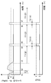
- FIG. 1 shows the schematic structure of the engine of one embodiment of the present invention. It is a figure explaining the 1st map of rail pressure in the common rail of the above-mentioned engine. It is a figure explaining the 2nd map of rail pressure in the common rail of the above-mentioned engine. It is a flowchart which shows the flow of control of the pump control apparatus of the said engine. It is a graph for demonstrating the relationship between the operating time of the said engine, and the said rail pressure. It is a figure which shows the relationship between the continuous operation time of an engine, and the dust density
- FSN dust density
- FIG. 1 is a simplified configuration diagram showing a schematic configuration of an engine according to an embodiment of the present invention.
- the engine of this embodiment includes a fuel pump 16, a common rail 120, four injectors 15, 15, 15, 15, a pressure sensor 12, a pump control device 21, and an engine speed sensor 13. And an engine control device 14.
- the pressure sensor 12 is an example of a pressure detection unit.
- the engine speed sensor 13 is an example of a rotation speed detector.
- the fuel pump 16 sucks fuel from the fuel tank 18 connected to the suction side of the fuel pump 16 through the fuel filter 121 and the low pressure pipe 122, and supplies the fuel to the common rail 120 through the high pressure pipe 123.
- the common rail 120 is formed in a cylindrical shape.
- the fuel supplied from the fuel pump 16 to the common rail 120 is stored in the common rail 120 at a high pressure.
- the injectors 15, 15, 15, and 15 inject high-pressure fuel supplied from the common rail 120 into each cylinder of an engine (not shown).
- the fuel is returned to the fuel tank 18 from the fuel pump 16 through the pump fuel return pipe 129. Further, the fuel is returned from the common rail 120 through the common rail fuel return pipe 131.
- the pressure sensor 12 detects the rail pressure (fuel pressure) in the common rail 120.
- the pressure sensor 12 sends a signal representing the rail pressure to the pump control device 21 and the engine control device 14.
- the engine speed sensor 13 detects the rotational speed of the engine.
- the engine speed sensor 13 sends a signal representing the rotational speed to the pump control device 21 and the engine control device 14.
- the engine control device 14 controls the fuel injection pressure, the injection timing, and the injection period of the injectors 15, 15, 15, 15 based on the signal from the pressure sensor 12 and the signal from the engine speed sensor 13.
- the engine control device 14 sends a signal representing the fuel injection period to the pump control device 21.
- the pump control device 21 has a CPU (Central Processing Unit) 210, a memory 216, and a counter 217.
- CPU Central Processing Unit
- the pump control device 21 receives the signal from the pressure sensor 12, the signal from the engine speed sensor 13, the time information and program stored in the memory 216, a control map described later, and the time measured by the counter 217. Based on this, the CPU 210 controls the fuel pump 16.
- the CPU 210 includes a rail pressure control unit 211, a rail pressure increase control unit 212, a pressure decrease determination unit 213, and a pressure increase determination unit 214.
- the pressure drop determination unit 213 has a predetermined pressure drop state in which the rail pressure is lower than a threshold value ⁇ (for example, 10 MPa, 30 MPa, 50 MPa, 70 MPa, 90 MPa) that is a first set value that is determined in advance. It is determined whether or not it has continued for one time ⁇ (for example, 10 hours, 20 hours, 30 hours, 40 hours, 50 hours).
- a threshold value ⁇ for example, 10 MPa, 30 MPa, 50 MPa, 70 MPa, 90 MPa
- the pressure increase determination unit 214 determines whether or not the pressure increase state equal to or greater than the threshold value ⁇ has continued for a predetermined second time ⁇ (for example, 1 minute, 5 minutes, 10 minutes, 15 minutes, 20 minutes) or more. Judging.
- the rail pressure control unit 211 and the rail pressure increase control unit 212 are based on the engine rotational speed detected by the engine speed sensor 13 and the fuel injection amount from the injectors 15, 15, 15, 15.
- the amount of fuel supplied to the 16 common rails 120 is controlled.
- the fuel injection amount is calculated from the injection periods of the injectors 15, 15, 15, 15.
- the rail pressure control unit 211 and the rail pressure increase control unit 212 set the rail pressure to a set pressure that is set based on a control map that is determined in advance from the engine speed and the fuel injection amount. Then, the fuel pump 16 is commanded.
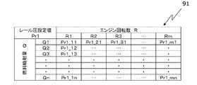
- FIG. 2A shows a first map 91 of the control map.
- FIG. 2B shows a second map 92 of the control map.
- the first and second maps 91 and 92 are maps representing the set value of the rail pressure from the relationship between the engine speed R and the fuel injection amount Q.
- each row of the first and second maps 91 and 92 corresponds to each engine speed R (R1, R2, R3,..., Rm).
- Each row of the first and second maps 91 and 92 corresponds to each fuel injection amount Q (Q1, Q2, Q3,..., Qm).
- Each cell of the first and second maps 91 and 92 indicates rail pressure set values Pr1_11, Pr1_12,..., Pr1_mn, Pr2_11, Pr2_12,. ing.
- the set values Pr1_11, Pr1_12..., Pr1_mn, Pr2_11, Pr2_12..., Pr2_mn are based on appropriate values calibrated by a master engine or the like, for example.
- the rail pressure set values Pr2_11, Pr2_12..., Pr2_mn set in the second map 92 are more than the corresponding set values Pr1_11, Pr1_12,... Pr1_mn of the corresponding rail pressure set in the first map 91. Each is a large value, and all are larger than the threshold value ⁇ .
- FIG. 3 is a flowchart showing the operation of the engine.
- FIG. 4 is a diagram for explaining the relationship between engine operating time and rail pressure.
- the rail pressure control unit 211 reads the first map 91 from the memory 216, and based on the first map 91, the set value of the rail pressure is determined from the engine rotation speed and the fuel injection amount. Pr1 is set (step S1).
- the rail pressure control unit 211 instructs the fuel pump 16 so that the rail pressure Pr becomes the set value Pr1. Based on this command, the fuel pump 16 supplies fuel to the common rail 120.
- step S2 the pressure drop determination unit 213 determines whether or not the rail pressure Pr is in a pressure drop state lower than the threshold value ⁇ . If the pressure drop determination unit 213 determines that the pressure is in a pressure drop state, the process proceeds to step S3. In step 3, the pressure drop determination unit 213 causes the counter 217 to start measuring the elapsed time T1.
- step S4 the pressure drop determination unit 213 determines whether or not the pressure drop state is in a similar manner to step S2. If the pressure drop determination unit 213 determines that it is not in a pressure drop state, the process returns to step S2, while if it is determined that it is in a pressure drop state, the process proceeds to step S5. Specifically, as shown in FIG. 4, when the rail pressure Pr becomes lower than the threshold value ⁇ (time t1, t3, t5, t7), the measurement of the elapsed time T1 is started. On the other hand, when the rail pressure Pr becomes equal to or higher than the threshold value ⁇ (time t2, t4, t6), the measurement of the elapsed time T1 is ended. When the engine is stopped during the measurement of the elapsed time T1, the measurement of the elapsed time T1 is temporarily stopped. Then, when the engine is restarted, the measurement of the elapsed time T1 is restarted from the stopped time.
- the threshold value ⁇ time t1, t
- step S5 of FIG. 3 the pressure drop determination unit 213 determines whether or not the elapsed time T1 is equal to or longer than the first time ⁇ . If the pressure drop determination unit 213 determines that the elapsed time T1 is not equal to or greater than the first time ⁇ , the process returns to step S4. On the other hand, if it is determined that the elapsed time T1 is equal to or greater than the first time ⁇ , the flag is set to 1. Proceed to S6.
- step S ⁇ b> 6 the rail pressure increase control unit 212 reads the second map 92 from the memory 216 when the flag is set to 1. Based on the second map 92, the rail pressure increase control unit 212 sets the set value Pr2 of the rail pressure from the engine speed and the fuel injection amount. This set value Pr2 is a value larger than the threshold value ⁇ (for example, a range of 1.01 to 1.5 times ⁇ ). The rail pressure increase control unit 212 commands the fuel pump 16 so that the rail pressure Pr becomes the set value Pr2. Based on this command, the fuel pump 16 supplies fuel to the common rail 120.
- step S7 the pressure increase determination unit 214 causes the counter 217 to start measuring the elapsed time T2 when the flag becomes 1. At this time, the measurement of the elapsed time T1 ends.
- the pressure increase determination unit 214 determines whether or not the elapsed time T2 is equal to or longer than the second time ⁇ .
- the flag is set to 0 and the process returns to step S1. That is, when the flag becomes 0, the rail pressure control unit 211 reads the first map 91 from the memory 216 and, based on the first map 91, sets the rail pressure based on the engine speed and the fuel injection amount. Set Pr1. Then, the rail pressure control unit 211 functions as a rail pressure decrease control unit, and commands the fuel pump 16 to decrease the rail pressure from the set value Pr2 to the set value Pr1. Based on this command, the fuel pump 16 supplies fuel to the common rail 120.
- the flag becomes 1
- the rail pressure Pr becomes Pr2 which is larger than the threshold value ⁇ .
- the flag becomes 1
- the measurement of the elapsed time T2 is started and the measurement of the elapsed time T1 is ended.
- the elapsed time T2 becomes ⁇ (time t5)
- the flag becomes 0, and the rail pressure Pr becomes Pr1 smaller than the threshold value ⁇ .
- the flag becomes 0, the measurement of the elapsed time T2 is completed and the measurement of the elapsed time T1 is started.
- the rail pressure increase control unit 212 causes the rail pressure to become the set value Pr2.
- the fuel pump 16 is commanded. For this reason, even if the engine is operated continuously for a long time in a low speed and low load region, the rail pressure is increased at an appropriate timing so as to become larger than the threshold value ⁇ , and the dust concentration in the exhaust gas discharged from the engine ( FSN) can be made below a limit value (for example, 0.1FSN, 0.2FSN, 0.3FSN, 0.4FSN, 0.5FSN). Therefore, the occurrence of Sd degradation can be suppressed.
- the rail pressure control unit 211 determines from the engine speed and the fuel injection amount based on the first map 91. A set value Pr1 of rail pressure is set. Then, the rail pressure control unit 211 instructs the fuel pump 16 so that the rail pressure becomes the set value Pr1, that is, the rail pressure decreases from the set value Pr2 to the set value Pr1. Therefore, the pressure increase state can be continued for an appropriate time, and the time during which the engine noise and vibration are generated as the rail pressure increases can be shortened.
- the rail pressure increase control unit 212 is based on a second map determined in advance from the engine rotation speed detected by the engine speed sensor 13 and the fuel injection amount from the injectors 15, 15, 15, 15.
- the fuel pump 16 is commanded to be the set value Pr2 of the rail pressure set in the above. Therefore, the rail pressure can be appropriately and easily controlled based on the operating condition of the engine.
- the rail pressure set value Pr2 is set to a value larger than the threshold value ⁇ which is the first set value.
- the set value of the rail pressure may be set to the same value as the first set value.
- the pressure decrease determination unit 213 ends the measurement of the elapsed time T1, while the pressure increase determination unit 214 Then, the measurement of the elapsed time T2 is started, and it is determined whether or not the elapsed time T2 is equal to or longer than the second time ⁇ .
- the measurement of the elapsed time T2 is not started and the measurement of the elapsed time T1 is continued, and the pressure increase determination unit determines whether or not the elapsed time T1 is equal to or longer than a predetermined time. Also good.
- the set value Pr1 or Pr2 of the rail pressure is set based on the engine speed and the fuel injection amount based on the first map 91 or the second map 92. It may be set from the injection amount. Further, the set value of the rail pressure may be a predetermined value.
- the rail pressure set value Pr 1 or Pr 2 is set based on the first map 91 or the second map 92.
- the set value of the rail pressure may be set based on a map selected from among a plurality of predetermined maps of three or more.
- the rail pressure increase control unit 212 sets the rail pressure set value Pr2 based on the second map 92.
- the rail pressure increase control unit adds a certain value (for example, 5 MPa, 10 MPa, 15 MPa, 20 MPa, etc.) to the set value of the rail pressure set based on the first map. It is good also as a set value of rail pressure.
- the rail pressure increase control unit 212 sets the set value Pr2 of the rail pressure based on the second map 92 while the flag is 1.
- the set value of the rail pressure may be increased by a certain constant value (for example, 10 MPa, 30 MPa, 50 MPa, 70 MPa, etc.) and then gradually decreased with the passage of time.
- the rail pressure is reduced to become the set value Pr1 that is smaller than the threshold value ⁇ . You may reduce so that it may become a slightly larger setting value.
Landscapes
- Engineering & Computer Science (AREA)
- Chemical & Material Sciences (AREA)
- Combustion & Propulsion (AREA)
- Mechanical Engineering (AREA)
- General Engineering & Computer Science (AREA)
- Electrical Control Of Air Or Fuel Supplied To Internal-Combustion Engine (AREA)
- Fuel-Injection Apparatus (AREA)
Abstract
エンジンは、燃料ポンプ(16)と、コモンレール(120)と、4つのインジェクタ(15,15,15,15)と、圧力センサ(12)と、ポンプ制御装置(21)とを備えている。ポンプ制御装置(21)は、レール圧上昇制御部(212)と、圧力低下判断部(213)とを有している。圧力センサ(12)は、コモンレール(120)内のレール圧を検出する。圧力低下(213)が、レール圧が予め定められた第1の設定値よりも低い圧力低下状態が、予め定められた第1の時間以上継続したと判断したとき、レール圧上昇制御部(212)は、レール圧が第1の設定値以上になるように、燃料ポンプ(16)からコモンレール(120)へ供給される燃料の供給量を制御する。
Description
本発明は、例えば冷凍機に搭載されるエンジンに関する。
従来、エンジンとしては、特開平10-9033号公報(特許文献1)に記載されているものがある。このエンジンは、コモンレールと、このコモンレールに接続されたインジェクタとを備えている。そして、このコモンレール内に高圧で蓄えられた燃料をインジェクタに供給し、インジェクタからの燃料の噴射圧力、噴射時期、噴射期間(噴射量)を制御して、エンジンから排出される窒素酸化物(NOx)の低減や、エンジンの騒音振動の低減を図るようにしている。
上記従来のエンジンでは、エンジンの回転速度および負荷に応じてコモンレール内のレール圧(燃料圧)は変更される。例えばエンジンを高速高負荷領域で運転したとき、レール圧は高く設定される一方、低速低負荷領域で運転したとき、レール圧は低く設定される。図5に示すように、エンジンをレール圧が高い状態で連続して運転したとき、エンジンから排出される排気ガス中の粉塵濃度(FSN:Filter Smoke Number)は、エンジンの運転開始から時間が経過しても略一定で、制限値L(例えば0.1FSN,0.2FSN,0.3FSN,0.4FSN,0.5FSN)に対して低い状態が維持される。
しかしながら、エンジンをレール圧が低い状態で長時間連続して運転すると、FSNは、エンジンの運転開始から時間の経過と共に上昇し、一定時間を経過すると制限値Lを越えてしまう。そして、FSNが大きくなることによって、黒煙の発生や未燃燃料の放出などのSd(スモークディメンジョン)劣化が発生するという問題があった。
そこで、本発明の課題は、低速低負荷領域で長時間連続して運転してもSd劣化が発生するのを抑制できるエンジンを提供することにある。
上記課題を解決するため、本発明のエンジンは、
燃料ポンプと、
上記燃料ポンプから供給された燃料を蓄えるコモンレールと、
上記コモンレールから供給された燃料を噴射するインジェクタと、
上記燃料ポンプから上記コモンレールへ供給される燃料の供給量を制御するポンプ制御装置と、
上記コモンレール内のレール圧を検出する圧力検出部と
を備え、
上記ポンプ制御装置は、
上記レール圧が予め定められた第1の設定値よりも低い圧力低下状態が、予め定められた第1の時間以上継続したか否かを判断する圧力低下判断部と、
上記圧力低下状態が上記第1の時間以上継続したと上記圧力低下判断部が判断したとき、上記レール圧が上記第1の設定値以上になるように、上記燃料の供給量を制御するレール圧上昇制御部と
を有していることを特徴としている。
燃料ポンプと、
上記燃料ポンプから供給された燃料を蓄えるコモンレールと、
上記コモンレールから供給された燃料を噴射するインジェクタと、
上記燃料ポンプから上記コモンレールへ供給される燃料の供給量を制御するポンプ制御装置と、
上記コモンレール内のレール圧を検出する圧力検出部と
を備え、
上記ポンプ制御装置は、
上記レール圧が予め定められた第1の設定値よりも低い圧力低下状態が、予め定められた第1の時間以上継続したか否かを判断する圧力低下判断部と、
上記圧力低下状態が上記第1の時間以上継続したと上記圧力低下判断部が判断したとき、上記レール圧が上記第1の設定値以上になるように、上記燃料の供給量を制御するレール圧上昇制御部と
を有していることを特徴としている。
本発明によれば、上記圧力低下判断部が、圧力低下状態が第1の時間以上継続したと判断したとき、レール圧上昇制御部は、レール圧が第1の設定値以上になるように、燃料の供給量を制御している。このため、エンジンを低速低負荷領域で長時間連続して運転しても、適切なタイミングでレール圧を第1の設定値以上に上昇させて、エンジンから排出される排気ガス中の粉塵濃度(FSN)を制限値以下にできる。したがって、Sd劣化が発生するのを抑制できる。
また、一実施形態では、
上記ポンプ制御装置は、
上記レール圧が上記設定値以上である圧力上昇状態が、予め定められた第2の時間以上継続したか否かを判断する圧力上昇判断部と、
上記圧力上昇状態が上記第2の時間以上継続したと上記圧力上昇判断部が判断したとき、上記レール圧が低下するように、上記燃料の供給量を制御するレール圧低下制御部と
を有している。
上記ポンプ制御装置は、
上記レール圧が上記設定値以上である圧力上昇状態が、予め定められた第2の時間以上継続したか否かを判断する圧力上昇判断部と、
上記圧力上昇状態が上記第2の時間以上継続したと上記圧力上昇判断部が判断したとき、上記レール圧が低下するように、上記燃料の供給量を制御するレール圧低下制御部と
を有している。
上記実施形態によれば、上記圧力上昇判断部が、圧力上昇状態が第2の時間以上継続したと判断したとき、レール圧低下制御部は、レール圧が低下するように、燃料の供給量を制御する。したがって、圧力上昇状態を適切な時間だけ継続させることができ、レール圧の上昇に伴うエンジンの騒音振動が生じる時間を短くできる。
また、一実施形態では、
上記エンジンの回転速度を検出する回転速度検出器を備え、
上記レール圧上昇制御部は、上記回転速度検出器が検出したエンジンの回転速度と、上記インジェクタからの燃料の噴射量とに基づいて、上記レール圧がエンジンの回転速度とインジェクタの燃料の噴射量とで予め定められた第2の設定値になるように、上記燃料の供給量を制御する。
上記エンジンの回転速度を検出する回転速度検出器を備え、
上記レール圧上昇制御部は、上記回転速度検出器が検出したエンジンの回転速度と、上記インジェクタからの燃料の噴射量とに基づいて、上記レール圧がエンジンの回転速度とインジェクタの燃料の噴射量とで予め定められた第2の設定値になるように、上記燃料の供給量を制御する。
上記実施形態によれば、上記レール圧上昇制御部が、回転速度検出器が検出したエンジンの回転速度とインジェクタからの燃料の噴射量とに基づいて、レール圧がエンジンの回転速度とインジェクタの燃料の噴射量とで予め定められた第2の設定値になるように、上記燃料の供給量を制御する。したがって、エンジンの運転状況に基づいて、レール圧を適切かつ容易に制御することができる。
本発明のエンジンによれば、低速低負荷領域で長時間連続して運転してもSd劣化が発生するのを抑制できる。
以下、本発明のエンジンを図示の実施形態により詳細に説明する。
図1は、本発明の一実施形態に係るエンジンの概略構成を示す簡略構成図である。
図1に示すように、この実施形態のエンジンは、燃料ポンプ16と、コモンレール120と、4つのインジェクタ15,15,15,15と、圧力センサ12と、ポンプ制御装置21と、エンジン速度センサ13と、エンジン制御装置14とを備えている。ここで、圧力センサ12は、圧力検出部の一例である。また、エンジン速度センサ13は、回転速度検出器の一例である。
上記燃料ポンプ16は、燃料ポンプ16の吸入側に接続された燃料タンク18から燃料フィルタ121および低圧管122を介して燃料を吸入し、高圧管123を介してコモンレール120に燃料を供給する。
上記コモンレール120は、円筒状に形成されている。燃料ポンプ16からコモンレール120に供給された燃料は、コモンレール120内に高圧で蓄えられる。
上記インジェクタ15,15,15,15は、コモンレール120から供給された高圧の燃料を図示しないエンジンの各気筒に噴射する。
上記燃料タンク18には、燃料ポンプ16からポンプ燃料戻り管129を介して、燃料が戻される。また、コモンレール120からコモンレール燃料戻り管131を介して、燃料が戻される。
上記圧力センサ12は、コモンレール120内のレール圧(燃料圧)を検出する。圧力センサ12は、このレール圧を表す信号をポンプ制御装置21およびエンジン制御装置14に送る。
上記エンジン速度センサ13は、エンジンの回転速度を検出する。エンジン速度センサ13は、この回転速度を表す信号をポンプ制御装置21およびエンジン制御装置14に送る。
上記エンジン制御装置14は、圧力センサ12からの信号と、エンジン速度センサ13からの信号とに基づいて、インジェクタ15,15,15,15による燃料の噴射圧力、噴射時期、噴射期間を制御する。エンジン制御装置14は、燃料の噴射期間を表す信号をポンプ制御装置21に送る。
上記ポンプ制御装置21は、CPU(中央処理装置)210と、メモリ216と、カウンター217とを有している。
上記ポンプ制御装置21は、圧力センサ12からの信号と、エンジン速度センサ13からの信号と、メモリ216に記憶された時間情報やプログラム、後述する制御マップなどと、カウンター217が計測する時間とに基づいて、CPU210によって、燃料ポンプ16を制御する。
上記CPU210は、レール圧制御部211と、レール圧上昇制御部212と、圧力低下判断部213と、圧力上昇判断部214とを有している。
上記圧力低下判断部213は、レール圧が予め定められた第1の設定値である閾値α(例えば、10MPa、30MPa、50MPa、70MPa、90MPa)よりも低い圧力低下状態が、予め定められた第1の時間β(例えば、10時間、20時間、30時間、40時間、50時間)以上継続したか否かを判断する。
上記圧力上昇判断部214は、閾値α以上の圧力上昇状態が、予め定められた第2の時間δ(例えば、1分、5分、10分、15分、20分)以上継続したか否かを判断する。
上記レール圧制御部211およびレール圧上昇制御部212は、エンジン速度センサ13によって検出されたエンジンの回転速度と、インジェクタ15,15,15,15からの燃料の噴射量とに基づいて、燃料ポンプ16のコモンレール120への燃料の供給量を制御する。ここで、燃料噴射量は、インジェクタ15,15,15,15の噴射期間から算出する。レール圧制御部211およびレール圧上昇制御部212は、具体的には、上記レール圧が、エンジンの回転速度と燃料噴射量とから予め定められた制御マップに基づいて設定した設定圧になるように、燃料ポンプ16に指令する。
図2Aは、上記制御マップの第1のマップ91を示している。図2Bは、上記制御マップの第2のマップ92を示している。
図2Aおよび図2Bに示すように、これら第1,第2のマップ91,92は、エンジン回転数Rと燃料噴射量Qとの関係からレール圧の設定値を表したマップである。ここで、第1,第2のマップ91,92の各列は、それぞれ各エンジン回転数R(R1,R2,R3,…,Rm)に対応している。また、第1,第2のマップ91,92の各行は、それぞれ各燃料噴射量Q(Q1,Q2,Q3,…,Qm)に対応している。第1,第2のマップ91,92の各セルは、エンジン回転数Rおよび燃料噴射量Qから設定されるレール圧の設定値Pr1_11,Pr1_12,…,Pr1_mn,Pr2_11,Pr2_12,…,Pr2_mnを示している。
上記設定値Pr1_11,Pr1_12…,Pr1_mn、Pr2_11,Pr2_12…,Pr2_mnは、例えば、マスターエンジンなどでキャリブレーションされた適正値に基づいている。第2のマップ92で設定されているレール圧の各設定値Pr2_11,Pr2_12…,Pr2_mnは、第1のマップ91で設定されている対応するレール圧の各設定値Pr1_11,Pr1_12…,Pr1_mnよりもそれぞれ大きい値であって、全て閾値αよりも大きい。
次に、図3および図4を参照して、上記構成のエンジンの動作を説明する。
図3は、エンジンの動作を示すフローチャートである。図4は、エンジンの運転時間とレール圧との関係を説明する図である。
図3に示すように、まず、レール圧制御部211は、メモリ216から第1のマップ91を読み出し、この第1のマップ91に基づいて、エンジン回転速度および燃料噴射量からレール圧の設定値Pr1を設定する(ステップS1)。レール圧制御部211は、レール圧Prが設定値Pr1になるように、燃料ポンプ16に指令する。この指令に基づいて、燃料ポンプ16は、コモンレール120に燃料を供給する。
次に、ステップS2に進んで、圧力低下判断部213は、レール圧Prが閾値αより低い圧力低下状態であるか否か判断する。圧力低下判断部213が圧力低下状態であると判断すると、ステップS3に進む。ステップ3では、圧力低下判断部213は、カウンター217に経過時間T1の計測を開始させる。
次に、ステップS4に進んで、圧力低下判断部213は、ステップS2と同様に圧力低下状態であるか否か判断する。圧力低下判断部213が圧力低下状態でないと判断すると、ステップS2に戻る一方、圧力低下状態であると判断すると、ステップS5に進む。具体的には、図4に示すように、レール圧Prが閾値αより低くなったとき(時間t1,t3,t5,t7)、経過時間T1の計測を開始する。一方、レール圧Prが閾値α以上となったとき(時間t2,t4,t6)、経過時間T1の計測を終了する。なお、経過時間T1の計測中にエンジンを停止したとき、経過時間T1の計測を一旦停止する。そしてエンジンを再度始動したとき、経過時間T1の計測をその停止した時間から再開する。
図3のステップS5では、圧力低下判断部213は、経過時間T1が第1の時間β以上であるか否か判断する。経過時間T1が第1の時間β以上ではないと圧力低下判断部213が判断すると、ステップS4に戻る一方、経過時間T1が第1の時間β以上であると判断すると、フラグを1にしてステップS6に進む。
ステップS6では、フラグが1になったことにより、レール圧上昇制御部212が、メモリ216から第2のマップ92を読み出す。この第2のマップ92に基づいて、レール圧上昇制御部212は、エンジン回転速度および燃料噴射量からレール圧の設定値Pr2を設定する。この設定値Pr2は、いずれも閾値αよりも大きい値(例えばαの1.01倍~1.5倍の範囲)である。レール圧上昇制御部212は、レール圧Prが設定値Pr2になるように燃料ポンプ16に指令する。この指令に基づいて、燃料ポンプ16は、コモンレール120に燃料を供給する。
次に、ステップS7に進んで、圧力上昇判断部214は、フラグが1になったことにより、カウンター217に経過時間T2の計測を開始させる。なお、このとき、経過時間T1の計測は終了する。
次に、ステップS8に進んで、圧力上昇判断部214は、経過時間T2が第2の時間δ以上であるか否か判断する。経過時間T2が第2の時間δ以上であると圧力上昇判断部214が判断すると、フラグを0にしてステップS1に戻る。つまり、フラグが0になると、レール圧制御部211が、メモリ216から第1のマップ91を読み出すと共に、この第1のマップ91に基づいて、エンジン回転速度および燃料噴射量からレール圧の設定値Pr1を設定する。そして、レール圧制御部211は、レール圧低下制御部として働いて、レール圧が設定値Pr2から設定値Pr1に低下するように燃料ポンプ16に指令する。この指令に基づいて、燃料ポンプ16は、コモンレール120に燃料を供給する。
具体的には、図4に示すように、レール圧Prが閾値αより小さいPr1であり、かつ、経過時間T1が第1の時間βになったとき(時間t4)、フラグが1になり、レール圧Prが閾値αより大きいPr2になる。フラグが1になると、経過時間T2の計測が開始されると共に、経過時間T1の計測が終了する。経過時間T2がδになったとき(時間t5)、フラグが0になり、レール圧Prが閾値αより小さいPr1になる。フラグが0になると、経過時間T2の計測が終了すると共に、経過時間T1の計測が開始される。
上記構成のエンジンによれば、圧力低下判断部213が、圧力低下状態が第1の時間β以上継続したと判断したとき、レール圧上昇制御部212は、レール圧が設定値Pr2になるように、燃料ポンプ16に指令する。このため、エンジンを低速低負荷領域で長時間連続して運転しても、適切なタイミングでレール圧を閾値αより大きくなるように上昇させて、エンジンから排出される排気ガス中の粉塵濃度(FSN)を、制限値(例えば0.1FSN,0.2FSN,0.3FSN,0.4FSN,0.5FSN)以下にできる。したがって、Sd劣化が発生するのを抑制できる。
また、圧力上昇判断部214が、圧力上昇状態が第2の時間δ以上継続したと判断したとき、レール圧制御部211は、第1のマップ91に基づいて、エンジン回転速度および燃料噴射量からレール圧の設定値Pr1を設定する。そして、レール圧制御部211は、レール圧が設定値Pr1になるように、つまりレール圧が設定値Pr2から設定値Pr1に低下するように、燃料ポンプ16に指令する。したがって、圧力上昇状態を適切な時間だけ継続させることができ、レール圧の上昇に伴うエンジンの騒音振動が生じる時間を短くできる。
また、レール圧上昇制御部212は、エンジン速度センサ13が検出したエンジンの回転速度と、インジェクタ15,15,15,15からの燃料の噴射量とから、予め定められた第2のマップに基づいて設定したレール圧の設定値Pr2になるように、燃料ポンプ16に指令する。したがって、エンジンの運転状況に基づいて、レール圧を適切かつ容易に制御することができる。
なお、上記実施形態では、レール圧の設定値Pr2を第1の設定値である閾値αよりも大きい値に設定した。しかしながら、この発明では、レール圧の設定値を第1の設定値と同じ値に設定してもよい。
また、上記実施形態では、レール圧が閾値α以上となったとき(フラグが1になったとき)、圧力低下判断部213は、経過時間T1の計測を終了させる一方、圧力上昇判断部214は、経過時間T2の計測を開始させ、経過時間T2が第2の時間δ以上であるか否か判断した。しかしながら、この発明では、経過時間T2の計測を開始せず、経過時間T1の計測を継続し、圧力上昇判断部は、この経過時間T1が所定の時間以上であるか否か判断するようにしてもよい。
また、上記実施形態では、レール圧の設定値Pr1またはPr2は、第1のマップ91または第2のマップ92に基づいて、エンジン回転速度および燃料噴射量から設定されたが、エンジン回転速度または燃料噴射量から設定されてもよい。また、レール圧の設定値は、予め定められた値であってもよい。
また、上記実施形態では、レール圧の設定値Pr1またはPr2は、第1のマップ91または第2のマップ92に基づいて設定された。しかしながら、この発明では、レール圧の設定値は、3つ以上の複数の予め定められたマップのうちから選択されたマップに基づいて設定されてもよい。
また、上記実施形態では、フラグが1になると、レール圧上昇制御部212が、第2のマップ92に基づいて、レール圧の設定値Pr2を設定した。しかしながら、この発明では、レール圧上昇制御部は、第1のマップに基づいて設定されたレール圧の設定値に、ある一定値(例えば、5MPa、10MPa、15MPa、20MPa等)を加算した値をレール圧の設定値としてもよい。
また、上記実施形態では、レール圧上昇制御部212は、フラグが1である間、第2のマップ92に基づいて、レール圧の設定値Pr2を設定した。しかしながら、この発明では、フラグが1になると、レール圧の設定値をある一定値(例えば、10MPa、30MPa、50MPa、70MPa等)分大きくした後、時間の経過とともに徐々に低下させてもよい。
また、上記実施形態では、経過時間T2が第2の時間δになったとき、レール圧を閾値αより小さい設定値Pr1になるように低下させたが、レール圧を閾値と同じにしたり、閾値より少し大きい設定値になるように低下させてもよい。
12 圧力センサ
13 エンジン速度センサ
15,15,15,15 インジェクタ
16 燃料ポンプ
21 ポンプ制御装置
120 コモンレール
211 レール圧制御部
212 レール圧上昇制御部
213 圧力低下判断部
214 圧力上昇判断部
13 エンジン速度センサ
15,15,15,15 インジェクタ
16 燃料ポンプ
21 ポンプ制御装置
120 コモンレール
211 レール圧制御部
212 レール圧上昇制御部
213 圧力低下判断部
214 圧力上昇判断部
Claims (3)
- 燃料ポンプと、
上記燃料ポンプから供給された燃料を蓄えるコモンレールと、
上記コモンレールから供給された燃料を噴射するインジェクタと、
上記燃料ポンプから上記コモンレールへ供給される燃料の供給量を制御するポンプ制御装置と、
上記コモンレール内のレール圧を検出する圧力検出部と
を備え、
上記ポンプ制御装置は、
上記レール圧が予め定められた第1の設定値よりも低い圧力低下状態が、予め定められた第1の時間以上継続したか否かを判断する圧力低下判断部と、
上記圧力低下状態が上記第1の時間以上継続したと上記圧力低下判断部が判断したとき、上記レール圧が上記第1の設定値以上になるように、上記燃料の供給量を制御するレール圧上昇制御部と
を有していることを特徴とするエンジン。 - 請求項1に記載のエンジンにおいて、
上記ポンプ制御装置は、
上記レール圧が上記設定値以上である圧力上昇状態が、予め定められた第2の時間以上継続したか否かを判断する圧力上昇判断部と、
上記圧力上昇状態が上記第2の時間以上継続したと上記圧力上昇判断部が判断したとき、上記レール圧が低下するように、上記燃料の供給量を制御するレール圧低下制御部と
を有していることを特徴とするエンジン。 - 請求項1または2に記載のエンジンにおいて、
上記エンジンの回転速度を検出する回転速度検出器を備え、
上記レール圧上昇制御部は、上記回転速度検出器が検出したエンジンの回転速度と、上記インジェクタからの燃料の噴射量とに基づいて、上記レール圧がエンジンの回転速度とインジェクタの燃料の噴射量とで予め定められた第2の設定値になるように、上記燃料の供給量を制御することを特徴とするエンジン。
Applications Claiming Priority (2)
| Application Number | Priority Date | Filing Date | Title |
|---|---|---|---|
| JP2013-094227 | 2013-04-26 | ||
| JP2013094227A JP6158580B2 (ja) | 2013-04-26 | 2013-04-26 | エンジン |
Publications (1)
| Publication Number | Publication Date |
|---|---|
| WO2014175272A1 true WO2014175272A1 (ja) | 2014-10-30 |
Family
ID=51791844
Family Applications (1)
| Application Number | Title | Priority Date | Filing Date |
|---|---|---|---|
| PCT/JP2014/061299 Ceased WO2014175272A1 (ja) | 2013-04-26 | 2014-04-22 | エンジン |
Country Status (2)
| Country | Link |
|---|---|
| JP (1) | JP6158580B2 (ja) |
| WO (1) | WO2014175272A1 (ja) |
Cited By (1)
| Publication number | Priority date | Publication date | Assignee | Title |
|---|---|---|---|---|
| JP2016156317A (ja) * | 2015-02-24 | 2016-09-01 | トヨタ自動車株式会社 | エンジンの燃圧制御装置 |
Citations (2)
| Publication number | Priority date | Publication date | Assignee | Title |
|---|---|---|---|---|
| JP2001107789A (ja) * | 1999-10-13 | 2001-04-17 | Fuji Heavy Ind Ltd | 筒内燃料噴射エンジンの燃料噴射制御装置 |
| JP2004278463A (ja) * | 2003-03-18 | 2004-10-07 | Nissan Motor Co Ltd | ディーゼルエンジンの制御装置 |
-
2013
- 2013-04-26 JP JP2013094227A patent/JP6158580B2/ja not_active Expired - Fee Related
-
2014
- 2014-04-22 WO PCT/JP2014/061299 patent/WO2014175272A1/ja not_active Ceased
Patent Citations (2)
| Publication number | Priority date | Publication date | Assignee | Title |
|---|---|---|---|---|
| JP2001107789A (ja) * | 1999-10-13 | 2001-04-17 | Fuji Heavy Ind Ltd | 筒内燃料噴射エンジンの燃料噴射制御装置 |
| JP2004278463A (ja) * | 2003-03-18 | 2004-10-07 | Nissan Motor Co Ltd | ディーゼルエンジンの制御装置 |
Cited By (1)
| Publication number | Priority date | Publication date | Assignee | Title |
|---|---|---|---|---|
| JP2016156317A (ja) * | 2015-02-24 | 2016-09-01 | トヨタ自動車株式会社 | エンジンの燃圧制御装置 |
Also Published As
| Publication number | Publication date |
|---|---|
| JP6158580B2 (ja) | 2017-07-05 |
| JP2014214703A (ja) | 2014-11-17 |
Similar Documents
| Publication | Publication Date | Title |
|---|---|---|
| JP2009162181A (ja) | NOxセンサ診断装置およびそれを用いた排気浄化システム | |
| JP4710961B2 (ja) | 燃料性状検出装置 | |
| JP6274690B2 (ja) | 燃料噴射制御方法及びコモンレール式燃料噴射制御装置 | |
| EP2696060A1 (en) | Fuel injection amount learning method for internal combustion engine | |
| JP2010261334A (ja) | 燃料噴射制御装置 | |
| JP4750978B2 (ja) | 供給燃料の漏れ検出方法 | |
| CN104066961A (zh) | 内燃机的控制装置 | |
| JP5245517B2 (ja) | エンジンの燃料噴射制御装置 | |
| JP6158580B2 (ja) | エンジン | |
| JP6149816B2 (ja) | 制御装置 | |
| JP6136855B2 (ja) | 噴射異常検出装置 | |
| JP2013096335A (ja) | デポジット検出方法及びコモンレール式燃料噴射制御装置 | |
| CN105705756A (zh) | 用于控制内燃机的电子控制器、方法、计算机程序以及电子的存储介质 | |
| JP6742100B2 (ja) | 燃料噴射制御装置、及び燃料噴射制御方法 | |
| JP5648646B2 (ja) | 燃料噴射制御装置 | |
| JP4735621B2 (ja) | 噴射量学習装置 | |
| WO2023011020A1 (zh) | 一种分缸空燃比自适应缸补偿控制方法 | |
| JP4421451B2 (ja) | 内燃機関用燃料供給システムの異常検出装置 | |
| JP2010185309A (ja) | ディーゼルエンジンの制御装置 | |
| JP6273904B2 (ja) | 圧力センサ異常検出装置 | |
| JP2007023796A (ja) | 燃料噴射装置 | |
| JP2004245053A (ja) | 内燃機関の燃料噴射制御装置 | |
| US10844806B2 (en) | Method and apparatus for detecting drift of pilot | |
| JP6172204B2 (ja) | 燃料噴射量制御装置の監視装置 | |
| JP2008280911A (ja) | コモンレール式燃料噴射システム |
Legal Events
| Date | Code | Title | Description |
|---|---|---|---|
| 121 | Ep: the epo has been informed by wipo that ep was designated in this application |
Ref document number: 14789019 Country of ref document: EP Kind code of ref document: A1 |
|
| NENP | Non-entry into the national phase |
Ref country code: DE |
|
| 122 | Ep: pct application non-entry in european phase |
Ref document number: 14789019 Country of ref document: EP Kind code of ref document: A1 |