WO2014175037A1 - ハウジングおよびその製造方法 - Google Patents
ハウジングおよびその製造方法 Download PDFInfo
- Publication number
- WO2014175037A1 WO2014175037A1 PCT/JP2014/059895 JP2014059895W WO2014175037A1 WO 2014175037 A1 WO2014175037 A1 WO 2014175037A1 JP 2014059895 W JP2014059895 W JP 2014059895W WO 2014175037 A1 WO2014175037 A1 WO 2014175037A1
- Authority
- WO
- WIPO (PCT)
- Prior art keywords
- housing
- chucked
- peripheral surface
- outer peripheral
- portions
- Prior art date
- Legal status (The legal status is an assumption and is not a legal conclusion. Google has not performed a legal analysis and makes no representation as to the accuracy of the status listed.)
- Ceased
Links
Images

Classifications
-
- F—MECHANICAL ENGINEERING; LIGHTING; HEATING; WEAPONS; BLASTING
- F04—POSITIVE - DISPLACEMENT MACHINES FOR LIQUIDS; PUMPS FOR LIQUIDS OR ELASTIC FLUIDS
- F04B—POSITIVE-DISPLACEMENT MACHINES FOR LIQUIDS; PUMPS
- F04B39/00—Component parts, details, or accessories, of pumps or pumping systems specially adapted for elastic fluids, not otherwise provided for in, or of interest apart from, groups F04B25/00 - F04B37/00
- F04B39/14—Provisions for readily assembling or disassembling
-
- B—PERFORMING OPERATIONS; TRANSPORTING
- B23—MACHINE TOOLS; METAL-WORKING NOT OTHERWISE PROVIDED FOR
- B23B—TURNING; BORING
- B23B31/00—Chucks; Expansion mandrels; Adaptations thereof for remote control
- B23B31/02—Chucks
-
- F—MECHANICAL ENGINEERING; LIGHTING; HEATING; WEAPONS; BLASTING
- F01—MACHINES OR ENGINES IN GENERAL; ENGINE PLANTS IN GENERAL; STEAM ENGINES
- F01C—ROTARY-PISTON OR OSCILLATING-PISTON MACHINES OR ENGINES
- F01C21/00—Component parts, details or accessories not provided for in groups F01C1/00 - F01C20/00
- F01C21/10—Outer members for co-operation with rotary pistons; Casings
-
- F—MECHANICAL ENGINEERING; LIGHTING; HEATING; WEAPONS; BLASTING
- F04—POSITIVE - DISPLACEMENT MACHINES FOR LIQUIDS; PUMPS FOR LIQUIDS OR ELASTIC FLUIDS
- F04B—POSITIVE-DISPLACEMENT MACHINES FOR LIQUIDS; PUMPS
- F04B39/00—Component parts, details, or accessories, of pumps or pumping systems specially adapted for elastic fluids, not otherwise provided for in, or of interest apart from, groups F04B25/00 - F04B37/00
- F04B39/12—Casings; Cylinders; Cylinder heads; Fluid connections
- F04B39/121—Casings
-
- B—PERFORMING OPERATIONS; TRANSPORTING
- B23—MACHINE TOOLS; METAL-WORKING NOT OTHERWISE PROVIDED FOR
- B23B—TURNING; BORING
- B23B31/00—Chucks; Expansion mandrels; Adaptations thereof for remote control
- B23B31/02—Chucks
- B23B31/10—Chucks characterised by the retaining or gripping devices or their immediate operating means
- B23B31/12—Chucks with simultaneously-acting jaws, whether or not also individually adjustable
- B23B31/16—Chucks with simultaneously-acting jaws, whether or not also individually adjustable moving radially
-
- F—MECHANICAL ENGINEERING; LIGHTING; HEATING; WEAPONS; BLASTING
- F04—POSITIVE - DISPLACEMENT MACHINES FOR LIQUIDS; PUMPS FOR LIQUIDS OR ELASTIC FLUIDS
- F04C—ROTARY-PISTON, OR OSCILLATING-PISTON, POSITIVE-DISPLACEMENT MACHINES FOR LIQUIDS; ROTARY-PISTON, OR OSCILLATING-PISTON, POSITIVE-DISPLACEMENT PUMPS
- F04C2230/00—Manufacture
- F04C2230/60—Assembly methods
- F04C2230/604—Mounting devices for pumps or compressors
-
- F—MECHANICAL ENGINEERING; LIGHTING; HEATING; WEAPONS; BLASTING
- F04—POSITIVE - DISPLACEMENT MACHINES FOR LIQUIDS; PUMPS FOR LIQUIDS OR ELASTIC FLUIDS
- F04C—ROTARY-PISTON, OR OSCILLATING-PISTON, POSITIVE-DISPLACEMENT MACHINES FOR LIQUIDS; ROTARY-PISTON, OR OSCILLATING-PISTON, POSITIVE-DISPLACEMENT PUMPS
- F04C2230/00—Manufacture
- F04C2230/85—Methods for improvement by repair or exchange of parts
-
- F—MECHANICAL ENGINEERING; LIGHTING; HEATING; WEAPONS; BLASTING
- F04—POSITIVE - DISPLACEMENT MACHINES FOR LIQUIDS; PUMPS FOR LIQUIDS OR ELASTIC FLUIDS
- F04C—ROTARY-PISTON, OR OSCILLATING-PISTON, POSITIVE-DISPLACEMENT MACHINES FOR LIQUIDS; ROTARY-PISTON, OR OSCILLATING-PISTON, POSITIVE-DISPLACEMENT PUMPS
- F04C2240/00—Components
- F04C2240/30—Casings or housings
-
- Y—GENERAL TAGGING OF NEW TECHNOLOGICAL DEVELOPMENTS; GENERAL TAGGING OF CROSS-SECTIONAL TECHNOLOGIES SPANNING OVER SEVERAL SECTIONS OF THE IPC; TECHNICAL SUBJECTS COVERED BY FORMER USPC CROSS-REFERENCE ART COLLECTIONS [XRACs] AND DIGESTS
- Y10—TECHNICAL SUBJECTS COVERED BY FORMER USPC
- Y10T—TECHNICAL SUBJECTS COVERED BY FORMER US CLASSIFICATION
- Y10T29/00—Metal working
- Y10T29/49—Method of mechanical manufacture
- Y10T29/49316—Impeller making
- Y10T29/4932—Turbomachine making
- Y10T29/49323—Assembling fluid flow directing devices, e.g., stators, diaphragms, nozzles
Definitions
- the present invention relates to a cylindrical housing used for an electric compressor or the like and a manufacturing method thereof.
- the electric compressor includes a cylindrical housing that houses a compression mechanism and a motor that drives the compression mechanism.
- Various devices including a cylindrical housing have been provided.
- Patent Document 1 discloses a flange-type motor including a bearing bracket having a flange on the load side.
- Patent Document 2 discloses a vane pump including a pump housing.
- Patent Document 3 discloses a screw compressor (fluid machine) including a hollow screw rotor.
- Patent Document 1 in order to machine the flange surface of the bearing bracket, it is axially positioned at the intermediate positions of the mounting seats provided at three locations in the circumferential direction of the outer peripheral surface of the bearing bracket. There is disclosed a technique in which trapezoidal chucking seats protruding in a band shape are provided at equal intervals and are processed by gripping them with a chuck on the processing machine side. Further, in Patent Document 2, a chucking surface having both side surfaces and end surfaces parallel to two intermediate positions of the mounting boss portion provided at four locations on the outer periphery of the pump housing is provided, and the both side surfaces are chucked to provide a machine. What is processed is disclosed.
- the male screw rotor is provided at the inner peripheral side of the opening of three tooth trace portions (tooth shape and hollow portion) arranged at equal intervals at an angle of 120 degrees with each other during machining.
- a linear part for chucking the rotor is formed, and the linear part is chucked with three chuck tools and cut.
- Patent Documents 1-3 a chucking seat and a chucking surface are provided in a portion that is easily chucked on the outer periphery of a housing or the like that is a workpiece, and these chucked portions are gripped by a chuck mechanism on the processing machine side.
- a chuck mechanism on the processing machine side Only what has been processed with is disclosed.
- the chucked part on the workpiece side is simply chucked by the chucking mechanism of the processing machine, deformation or distortion caused by chucking or when the housing is rotated at the time of processing in a housing provided with mounting legs etc. on the outer peripheral surface It is difficult to avoid deformation due to the centrifugal force, and in order to minimize the deformation and distortion, it is important to selectively set the chucked portion.
- machining accuracy it is important to minimize deformation and distortion due to chucking during machining, deformation due to centrifugal force, etc.
- the level of machining accuracy depends on the setting of the chucked part. It is no exaggeration to say that it is becoming an indispensable factor to improve the quality of the housing and to further improve the accuracy and performance of products using the housing, and countermeasures are required. It is in the situation that is being.
- the present invention has been made in view of such circumstances, and improves machining accuracy by minimizing deformation or distortion due to chucking or deformation due to centrifugal force when machining a cylindrical housing. It is an object of the present invention to provide a high quality housing and a method for manufacturing the same.
- the housing and the manufacturing method thereof according to the present invention employ the following means. That is, the housing according to the first aspect of the present invention has a cylindrical shape and is provided with a bearing member installation portion for installing the bearing member at least at one location on the inner circumferential surface thereof, and at least on the outer circumferential surface side.
- a chucked part to which the mechanism is chucked is set.
- At least three locations in the circumferential direction on the outer peripheral surface side corresponding to the portion where the bearing member installation portion of the cylindrical housing provided with the bearing member installation portion is provided are processed.
- a chucked part to be chucked by the chucking mechanism on the processing machine side is set.
- at least three chucked parts provided on the outer peripheral surface side corresponding to the relatively rigid part provided with the bearing member installation part on the inner peripheral side for example, It can be processed by chucking with a claw of a chuck mechanism of a processing machine such as a lathe. Accordingly, it is possible to manufacture a high-quality housing by minimizing the deformation and distortion of the housing due to chucking and improving the processing accuracy.
- the housing according to the second aspect of the present invention is the above-mentioned housing, wherein the chucked portion is a chucked portion comprising a flat cylindrical surface formed integrally with an outer peripheral surface of the housing. It is composed of a seating surface.
- the chucked portion is configured by a chucked seating surface comprising a flat cylindrical surface formed integrally with the outer peripheral surface of the housing. For this reason, by chucking the chucked seating surface, which is a flat cylindrical surface that is integrated with the outer peripheral surface, with the chuck mechanism on the processing machine side, the housing is chucked to prevent positional displacement and backlash. Can be machined. Therefore, it is possible to manufacture the housing with high processing accuracy by processing the housing with deformation, distortion or error due to chucking to a minimum.
- the chucked portions are provided at equal intervals in the circumferential direction of the outer peripheral surface of the housing.
- the chucked parts are provided at equal intervals in the circumferential direction of the outer peripheral surface of the housing. For this reason, the chucked portions provided at equal intervals in at least three locations in the circumferential direction of the cylindrical housing are chucked so that the chucking mechanism on the processing machine side is balanced at three locations so that displacement and backlash do not occur.
- the housing can be fixed and processed. Accordingly, the processing accuracy can be improved by uniformizing and minimizing deformation and distortion caused by chucking of the housing.
- the upper and lower mounting legs are provided in pairs on the vertical axis perpendicular to the axial direction of the cylindrical housing.
- One of the chucked portions provided at at least three locations in the circumferential direction of the outer peripheral surface of the housing is positioned on the vertical axis.
- the two upper and lower mounting legs are provided in pairs on the vertical axis perpendicular to the axial direction of the cylindrical housing, and are provided at at least three locations in the circumferential direction of the outer peripheral surface of the housing.
- One of the chucked parts to be chucked is positioned on the vertical axis.
- the housing according to the fifth aspect of the present invention is any one of the above-described housings, wherein the housing is a housing for an electric compressor constituting an outer shell of the electric compressor.
- the housing is a housing for an electric compressor that constitutes an outer shell of the electric compressor.
- the housing for electric compressors which constitutes the outer shell of the electric compressor can be made into a housing with high processing accuracy in which deformation and distortion during processing are minimized. Therefore, by incorporating the electric compression mechanism into the housing with high processing accuracy, it is possible to manufacture a high-precision and high-performance electric compressor without assembly errors.
- a flange portion for fastening with the third housing is integrally formed on each side portion of the pair of mounting legs provided at the two upper and lower portions. Molded.
- the flange portions for fastening with the third housing are respectively integrally formed on both side portions of the pair of mounting legs provided at the two upper and lower portions. For this reason, the flange portion for fastening with the third housing and the mounting leg are provided in the same direction, and the deformation due to the centrifugal force when the housing is rotated by them is chucked from three places by the chuck mechanism on the processing machine side. By canceling according to the deformation at the time of doing, the deformation at the time of housing processing can be minimized. Thereby, the processing accuracy of the housing can be improved, and a high-quality housing with less deformation and distortion can be manufactured.
- a housing according to a seventh aspect of the present invention is the housing according to any one of the above-mentioned housings, wherein the refrigerant gas suction port is integrally formed in contact with the upper mounting legs of the two upper and lower mounting legs. Has been.
- the refrigerant gas suction port is integrally formed in contact with the upper mounting leg of the two upper and lower mounting legs. For this reason, the refrigerant suction port and the mounting leg are provided in the same direction, and the deformation due to the centrifugal force when the housing is rotated by them is matched with the deformation when chucking from three places by the chuck mechanism on the processing machine side. By canceling, deformation at the time of housing processing can be minimized, and this also increases the processing accuracy of the housing and makes it possible to manufacture a high-quality housing with less deformation and distortion.
- the chucked portion is chucked by a chuck mechanism on the processing machine side, and the housing is rotated.
- a housing is manufactured by machining a required part.
- the chucked portion is chucked by the chuck mechanism on the machining machine side, and the required part is machined while rotating the housing.
- the housing is manufactured.
- at least three chucked portions provided on the outer peripheral surface side corresponding to the relatively high rigidity portion provided with the bearing member installation portion on the inner peripheral side, for example, a lathe A required part can be processed while chucking with a chuck mechanism of a processing machine or the like and rotating the housing. Accordingly, it is possible to manufacture a high-quality housing by minimizing the deformation and distortion of the housing due to chucking and improving the processing accuracy.
- the housing when machining the housing, at least three chucked portions provided on the outer peripheral surface side corresponding to the relatively rigid portion provided with the bearing member installation portion on the inner peripheral side are provided. For example, it can be processed by chucking with a claw of a chuck mechanism of a processing machine such as a lathe. For this reason, the deformation
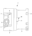
- FIG. 2A and 2B are schematic views (A) and (B) showing a positional relationship between a mounting leg provided on the outer peripheral surface of the housing shown in FIG. 1 and a chucked portion.
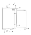
- FIG. 1 is a side view of an electric compressor housing according to an embodiment of the present invention
- FIG. 2 is a plan view thereof
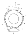
- FIG. 3 is a bottom view
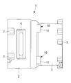
- FIG. FIG. 5 is a left side view
- FIG. 5 is a vertical cross sectional view
- FIG. 6 is a schematic diagram (A) and (B) showing the positional relationship between the mounting leg and the chucked portion.
- a housing (housing) 1 for an electric compressor according to the present embodiment constitutes an outer shell of the electric compressor, and has a motor housing portion 2 having a large diameter for housing a motor and a compression mechanism having a slightly smaller diameter.
- a compressor housing portion 3 that accommodates a cylindrical housing made of aluminum alloy that is integrally die-cast.
- the housing 1 is integrally formed with a bearing member installation portion 4 that rotatably supports the drive shaft on the inner peripheral surface side and installs a bearing member for incorporating a compression mechanism. .
- the bearing member installation part 4 as a boundary, the left side in the figure is the motor housing part 2 and the right side is the compressor housing part 3, and a motor and a compression mechanism (not shown) are accommodated and installed in each. Yes.
- a pair of mounting legs 5 and 6 are provided at two upper and lower positions on a vertical axis perpendicular to the axial direction of the housing 1.
- a flange portion for fastening with an inverter accommodating housing that is a third housing so as to be positioned on the housing end surface at both side portions of the upper and lower pair of mounting legs 5, 6. 7 is integrally formed in a total of four places, two at each of the upper and lower portions, and a refrigerant gas intake port 8 is integrally formed so as to be in contact with the mounting leg 5 on the upper side.
- fastening flange portions 9 with a discharge housing (not shown) which is a third housing are provided at a plurality of positions at equal intervals so as to be located on the housing end surface. Yes.
- a chucked portion 10 for chucking the housing 1 by a chuck mechanism on the lathe side is provided in the circumferential direction.
- at least three places are set at equal intervals.
- the chucked portion 10 provided in at least three places has an outer peripheral surface corresponding to an installation site of the bearing member installation portion 4 having relatively high rigidity by providing the bearing member installation portion 4 on the inner peripheral surface side. It will be provided on the side.
- the chucked portion 10 is constituted by a seat surface (sucked seat surface) 11 formed of a flat cylindrical surface formed integrally with the outer peripheral surface of the housing 1. Furthermore, as shown in FIGS. 6A and 6B, the chucked portions 10 (chucked seat surfaces 11) provided at the three circumferential directions are each provided with bearing member mounting portions 4 on the inner peripheral surface.
- the pair of mounting legs 5 and 6 are provided at two upper and lower positions on the vertical axis as in the present embodiment, as shown in FIG. As shown in FIG. 6A, it is desirable to provide one of the chucked portions 10 on the same vertical axis as the mounting legs 5 and 6.
- the following operational effects can be obtained.
- a processing machine such as a lathe
- three chucked portions 10 (chucked seating surfaces 11) provided on the outer peripheral surface of the housing 1 are turned on the lathe.
- the inner peripheral surface can be processed.
- the housing 1 can be chucked at a relatively rigid portion where the bearing member installation portion 4 is provided, deformation and distortion due to chucking can be minimized.
- the amount of deformation in the centrifugal direction of the upper and lower parts where the mounting legs 5, 6 and the like are provided is increased by centrifugal force due to the rotation of the housing 1, but the chucked portions 10 provided at three places in the circumferential direction are increased. Since one is provided on the same vertical axis as the mounting legs 5 and 6, the deformation due to the centrifugal force can be canceled in accordance with the deformation when chucking from three places by the chuck mechanism on the processing machine side. it can. For this reason, the deformation
- At least three locations in the circumferential direction on the outer peripheral surface side corresponding to the portion where the bearing member installation portion 4 of the cylindrical housing 1 provided with the bearing member installation portion 4 is provided.
- a chucked portion 10 (chucked seating surface 11) to be chucked by a chuck mechanism on the processing machine side is provided.
- at least three chucked portions 10 provided on the outer peripheral surface side corresponding to a relatively rigid portion where the bearing member installation portion 4 is provided on the inner peripheral surface. can be chucked and processed by a chuck mechanism of a processing machine such as a lathe. Accordingly, it is possible to manufacture the high-quality housing 1 by minimizing deformation and distortion of the housing 1 due to chucking and improving processing accuracy.
- the chucked portion 10 is constituted by a seat surface 11 for chucking which is a flat cylindrical surface provided on the outer peripheral portion of the housing 1. For this reason, by chucking the chucked seating surface 11 formed of a flat cylindrical surface integrated with the outer peripheral surface by the chuck mechanism on the processing machine side, the housing 1 is prevented from being displaced or rattled. Can be king and machined. Therefore, it is possible to manufacture the housing 1 with high processing accuracy by processing the housing 1 with deformation, distortion, or error due to chucking to a minimum.
- the chucked portion 10 is configured to be provided at equal intervals in the circumferential direction of the outer peripheral surface of the housing 1. For this reason, the chucked portions 10 provided at equal intervals in at least three locations in the circumferential direction of the cylindrical housing 1 are balanced at three locations by the chuck mechanism on the processing machine side so as not to be displaced or loose.
- the housing 1 can be fixed by chucking and processed. Accordingly, the processing accuracy can be improved by uniformizing and minimizing deformation and distortion caused by chucking of the housing 1.
- the upper and lower mounting legs 5 and 6 are provided in pairs on the vertical axis perpendicular to the axial direction of the cylindrical housing 1, and at least three in the circumferential direction of the outer peripheral surface of the housing 1.
- One of the chucked portions 10 provided at equal intervals is provided so as to be positioned on the same vertical axis.
- the housing 1 is the housing 1 for an electric compressor that constitutes the outer shell of the electric compressor.
- the housing 1 for electric compressors which comprises the outer shell of an electric compressor can be made into the housing 1 with the high process precision which minimized the deformation
- the electric compression mechanism into the housing 1 with high processing accuracy, a high-precision and high-performance electric compressor without assembly errors can be manufactured.
- a flange portion 7 for fastening with the third housing is integrally formed on both side portions of the pair of mounting legs 5 and 6 provided at two upper and lower portions, and further, the refrigerant gas is in contact with the upper mounting leg 5.
- the suction port 8 is integrally formed.
- a quality housing 1 can be manufactured.
- the housing 1 when machining the housing 1, by chucking the chucked portion 10 (chucking seat surface 11) with a chuck mechanism on the processing machine side and machining the required portion while rotating the housing 1, The housing 1 is manufactured. For this reason, at the time of processing the housing 1, at least three chucked parts 10 provided on the outer peripheral surface side corresponding to the relatively high rigidity part provided with the bearing member installation part 4 on the inner peripheral side, A required part can be processed while chucking by a chuck mechanism of a processing machine such as a lathe and rotating the housing 1. Therefore, also by the housing manufacturing method of this embodiment, the deformation
- this invention is not limited to the invention concerning the said embodiment, In the range which does not deviate from the summary, it can change suitably.
- the chucked seat surface 11 made of a flat dedicated cylindrical surface is provided on the outer peripheral surface of the housing 1 as the chucked portion 10 has been described. If the chucked part 10 is a flat cylindrical surface, the outer peripheral surface of the housing 1 may be directly used as the chucked part 10, and the present invention includes such a form. .
Landscapes
- Engineering & Computer Science (AREA)
- Mechanical Engineering (AREA)
- General Engineering & Computer Science (AREA)
- Compressor (AREA)
- Applications Or Details Of Rotary Compressors (AREA)
Priority Applications (3)
| Application Number | Priority Date | Filing Date | Title |
|---|---|---|---|
| US14/770,735 US10138879B2 (en) | 2013-04-23 | 2014-04-03 | Housing and method of manufacturing the same |
| CN201480016602.4A CN105163885B (zh) | 2013-04-23 | 2014-04-03 | 壳体及其制造方法 |
| DE112014002089.3T DE112014002089B4 (de) | 2013-04-23 | 2014-04-03 | Gehäuse und Vefahren zum Herstellen desselben |
Applications Claiming Priority (2)
| Application Number | Priority Date | Filing Date | Title |
|---|---|---|---|
| JP2013090452A JP6189077B2 (ja) | 2013-04-23 | 2013-04-23 | ハウジングおよびその製造方法 |
| JP2013-090452 | 2013-04-23 |
Publications (1)
| Publication Number | Publication Date |
|---|---|
| WO2014175037A1 true WO2014175037A1 (ja) | 2014-10-30 |
Family
ID=51791618
Family Applications (1)
| Application Number | Title | Priority Date | Filing Date |
|---|---|---|---|
| PCT/JP2014/059895 Ceased WO2014175037A1 (ja) | 2013-04-23 | 2014-04-03 | ハウジングおよびその製造方法 |
Country Status (5)
| Country | Link |
|---|---|
| US (1) | US10138879B2 (enExample) |
| JP (1) | JP6189077B2 (enExample) |
| CN (1) | CN105163885B (enExample) |
| DE (1) | DE112014002089B4 (enExample) |
| WO (1) | WO2014175037A1 (enExample) |
Families Citing this family (3)
| Publication number | Priority date | Publication date | Assignee | Title |
|---|---|---|---|---|
| CN107514352A (zh) * | 2016-06-15 | 2017-12-26 | 无锡市华琳制冷设备有限公司 | 一种空调压缩机扩涨式壳体 |
| JP6890070B2 (ja) * | 2017-09-05 | 2021-06-18 | 三菱重工サーマルシステムズ株式会社 | 圧縮機ケーシングの製造方法、ケーシング素材 |
| CN110480041B (zh) * | 2018-05-15 | 2024-06-14 | 西安西玛电机有限公司 | 一种电机凸缘端盖一刀车装置 |
Citations (4)
| Publication number | Priority date | Publication date | Assignee | Title |
|---|---|---|---|---|
| JPH06712A (ja) * | 1992-06-19 | 1994-01-11 | Hitachi Ltd | 旋回スクロールの加工法 |
| US6289776B1 (en) * | 1999-07-02 | 2001-09-18 | Copeland Corporation | Method and apparatus for machining bearing housing |
| JP2003120554A (ja) * | 2001-10-18 | 2003-04-23 | Mitsubishi Heavy Ind Ltd | スクロール型圧縮機 |
| JP2006322385A (ja) * | 2005-05-19 | 2006-11-30 | Mitsubishi Heavy Ind Ltd | ハウジング及びハウジングの製造方法 |
Family Cites Families (9)
| Publication number | Priority date | Publication date | Assignee | Title |
|---|---|---|---|---|
| JPS569044B2 (enExample) | 1975-02-14 | 1981-02-27 | ||
| JPS59179462U (ja) * | 1983-05-17 | 1984-11-30 | 株式会社東芝 | 回転電機のベヤリングブラケツト |
| JP2686742B2 (ja) * | 1987-06-16 | 1997-12-08 | 株式会社 ユニシアジェックス | ベーンポンプ |
| JP3569044B2 (ja) * | 1995-08-17 | 2004-09-22 | 栃木富士産業株式会社 | 流体機械 |
| JP3682819B2 (ja) * | 1997-10-22 | 2005-08-17 | 豊和工業株式会社 | チャック |
| JP3976466B2 (ja) * | 2000-02-23 | 2007-09-19 | カヤバ工業株式会社 | ギヤポンプ |
| DE10351372A1 (de) * | 2003-11-04 | 2005-06-16 | Zexel Valeo Compressor Europe Gmbh | Kompressor, insbesondere für die Klimaanlage eines Kraftfahrzeuges |
| JP4663462B2 (ja) * | 2005-09-21 | 2011-04-06 | サンデン株式会社 | 往復動圧縮機 |
| JP4799180B2 (ja) * | 2006-01-05 | 2011-10-26 | サンデン株式会社 | 電動圧縮機 |
-
2013
- 2013-04-23 JP JP2013090452A patent/JP6189077B2/ja active Active
-
2014
- 2014-04-03 CN CN201480016602.4A patent/CN105163885B/zh active Active
- 2014-04-03 WO PCT/JP2014/059895 patent/WO2014175037A1/ja not_active Ceased
- 2014-04-03 DE DE112014002089.3T patent/DE112014002089B4/de active Active
- 2014-04-03 US US14/770,735 patent/US10138879B2/en active Active
Patent Citations (4)
| Publication number | Priority date | Publication date | Assignee | Title |
|---|---|---|---|---|
| JPH06712A (ja) * | 1992-06-19 | 1994-01-11 | Hitachi Ltd | 旋回スクロールの加工法 |
| US6289776B1 (en) * | 1999-07-02 | 2001-09-18 | Copeland Corporation | Method and apparatus for machining bearing housing |
| JP2003120554A (ja) * | 2001-10-18 | 2003-04-23 | Mitsubishi Heavy Ind Ltd | スクロール型圧縮機 |
| JP2006322385A (ja) * | 2005-05-19 | 2006-11-30 | Mitsubishi Heavy Ind Ltd | ハウジング及びハウジングの製造方法 |
Also Published As
| Publication number | Publication date |
|---|---|
| US10138879B2 (en) | 2018-11-27 |
| US20160010633A1 (en) | 2016-01-14 |
| DE112014002089B4 (de) | 2018-03-22 |
| JP6189077B2 (ja) | 2017-08-30 |
| DE112014002089T5 (de) | 2016-01-07 |
| JP2014214633A (ja) | 2014-11-17 |
| CN105163885B (zh) | 2017-08-08 |
| CN105163885A (zh) | 2015-12-16 |
Similar Documents
| Publication | Publication Date | Title |
|---|---|---|
| JP6702318B2 (ja) | 送風装置および掃除機 | |
| JP6682769B2 (ja) | ポンプ装置 | |
| JP2010180877A (ja) | ブリスク型ロータホイール翼端の製造方法 | |
| EP2679826B1 (en) | Rotor and corresponding manufacturing method | |
| TWI575852B (zh) | 真空泵用馬達及具備該真空泵用馬達之真空泵 | |
| JP2014020255A (ja) | インペラ回転体およびインペラ回転体の組立方法 | |
| JP6189077B2 (ja) | ハウジングおよびその製造方法 | |
| JP6651267B2 (ja) | 回転電機の固定子およびその製造方法 | |
| US8246300B2 (en) | Vacuum pump | |
| TWI566881B (zh) | Rotating device | |
| JP2012159034A (ja) | ファン用防振ボス | |
| JP2014214633A5 (enExample) | ||
| CN106329868A (zh) | 电机及具有该电机的电动车辆、混合动力车辆 | |
| JP6203344B1 (ja) | モータの組み立て治具および組み立て方法 | |
| CN114556751A (zh) | 旋转电机 | |
| TWI662869B (zh) | 加工機組件之驅動裝置 | |
| JP2012070583A (ja) | 回転電機およびハウジング加工方法 | |
| CN108430695B (zh) | 机床 | |
| CN206117421U (zh) | 一种无刷电机电路板的连接装置 | |
| JP2012170314A (ja) | モータ | |
| WO2012008150A1 (en) | Fixing structure and drive apparatus | |
| JP2024064050A (ja) | モータハウジング、およびモータハウジングの製造方法 | |
| TWM578906U (zh) | Motor housing package structure | |
| TWI495811B (zh) | 滾珠螺桿裝置的製造方法及其組件的硏磨加工方法 | |
| JPS58103861A (ja) | 電動機の製造方法 |
Legal Events
| Date | Code | Title | Description |
|---|---|---|---|
| WWE | Wipo information: entry into national phase |
Ref document number: 201480016602.4 Country of ref document: CN |
|
| 121 | Ep: the epo has been informed by wipo that ep was designated in this application |
Ref document number: 14787755 Country of ref document: EP Kind code of ref document: A1 |
|
| WWE | Wipo information: entry into national phase |
Ref document number: 14770735 Country of ref document: US |
|
| WWE | Wipo information: entry into national phase |
Ref document number: 112014002089 Country of ref document: DE Ref document number: 1120140020893 Country of ref document: DE |
|
| 122 | Ep: pct application non-entry in european phase |
Ref document number: 14787755 Country of ref document: EP Kind code of ref document: A1 |