WO2014174782A1 - 流量制御用の多孔型オリフィスプレート及びこれを用いた流量制御装置 - Google Patents
流量制御用の多孔型オリフィスプレート及びこれを用いた流量制御装置 Download PDFInfo
- Publication number
- WO2014174782A1 WO2014174782A1 PCT/JP2014/002041 JP2014002041W WO2014174782A1 WO 2014174782 A1 WO2014174782 A1 WO 2014174782A1 JP 2014002041 W JP2014002041 W JP 2014002041W WO 2014174782 A1 WO2014174782 A1 WO 2014174782A1
- Authority
- WO
- WIPO (PCT)
- Prior art keywords
- orifice plate
- orifice
- flow rate
- pressure
- control
- Prior art date
Links
Images


Classifications
-
- F—MECHANICAL ENGINEERING; LIGHTING; HEATING; WEAPONS; BLASTING
- F16—ENGINEERING ELEMENTS AND UNITS; GENERAL MEASURES FOR PRODUCING AND MAINTAINING EFFECTIVE FUNCTIONING OF MACHINES OR INSTALLATIONS; THERMAL INSULATION IN GENERAL
- F16L—PIPES; JOINTS OR FITTINGS FOR PIPES; SUPPORTS FOR PIPES, CABLES OR PROTECTIVE TUBING; MEANS FOR THERMAL INSULATION IN GENERAL
- F16L55/00—Devices or appurtenances for use in, or in connection with, pipes or pipe systems
- F16L55/02—Energy absorbers; Noise absorbers
- F16L55/027—Throttle passages
- F16L55/02709—Throttle passages in the form of perforated plates
- F16L55/02718—Throttle passages in the form of perforated plates placed transversely
-
- G—PHYSICS
- G05—CONTROLLING; REGULATING
- G05D—SYSTEMS FOR CONTROLLING OR REGULATING NON-ELECTRIC VARIABLES
- G05D7/00—Control of flow
- G05D7/06—Control of flow characterised by the use of electric means
- G05D7/0617—Control of flow characterised by the use of electric means specially adapted for fluid materials
- G05D7/0629—Control of flow characterised by the use of electric means specially adapted for fluid materials characterised by the type of regulator means
- G05D7/0635—Control of flow characterised by the use of electric means specially adapted for fluid materials characterised by the type of regulator means by action on throttling means
Definitions
- the present invention relates to an improvement in an orifice plate for flow rate control and a pressure control type flow rate control device using the same, and in particular, in a pressure control type flow rate control device used in a gas supply device for semiconductor manufacturing equipment, etc.
- a wide flow rate range can be obtained.
- the present invention relates to a porous orifice plate for flow rate control capable of performing highly accurate flow rate control over a wide range, and a pressure control type flow rate control device using the same.
- FIG. 13 shows an example of the configuration of a pressure control type flow control device using an orifice previously disclosed by the present inventors.
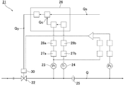
- the flow control device 21 includes a control valve 22, a pressure detector 23, and a temperature detector. 24, an orifice 25, an arithmetic and control unit 26, amplifiers 27a and 27b, A / D conversions 28a and 28b, etc. (Japanese Patent Laid-Open No. 8-338546).
- the flow command values Qs and Qc are compared, and a control signal Qy corresponding to the difference Qc ⁇ Qs between them is input to the drive unit 30 of the control valve 22.
- the control valve 22 is controlled to be opened and closed by the control signal Qy so that the difference Qc ⁇ Qs between the two becomes zero, whereby the flow rate downstream of the orifice 25 is always held at the set flow rate (flow rate command value) Qs. .
- the orifice 25 is formed by punching one small hole having an inner diameter of 0.01 to 0.20 mm by pressing, electric discharge machining or etching on a metal plate having a thickness of 0.02 to 0.20 mm.
- the hole diameter of the orifice is appropriately selected according to the required control flow rate of the gas.
- the orifice 25 is generally formed by electric discharge machining or etching. However, in order to reduce the machining cost, the orifice may be formed by so-called cutting using a drill weight (special feature). Kaihei 11-117915).
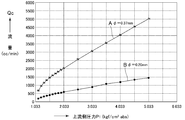
- FIG. 14 shows the flow rate control characteristics when the gas is nitrogen gas in the pressure control type flow rate control device of FIG. 13, and shows the case where the downstream side of the orifice 25 is atmospheric pressure.
- the upstream pressure P 1 is at a range greater than about 2 times the downstream pressure P 2
- flow rate Qc and a P 1 is held in a linear relationship
- Qc orifice will be directly proportional to the pressure P 1 on the upstream side, an orifice upstream side pressure P 1 by automatic control, it is possible to perform the flow rate of the feedback control that flow orifice.
- A shows the flow rate control characteristics when the orifice has a hole diameter of 0.37 mm ⁇ and B shows 0.20 ⁇ .
- both lines A and B have good linearity in the range of P 2 ⁇ 0.5P 1 (that is, P 2 / P 1 ⁇ 0.5). , enables highly accurate flow rate control by adjusting the P 1.
- control range of the critical pressure ratio P 2 / P 1 decreases as the control flow rate of the flow rate control device increases and the orifice diameter increases, and gas is supplied to the vacuum chamber of the semiconductor manufacturing apparatus. In some cases, various inconveniences occur.
- the pressure ratio P 2 / P 1 at which the critical expansion condition is satisfied changes as the orifice diameter increases.
- the actual critical expansion is caused by the difficulty that the flow rate (pressure) control range fluctuates.
- the present invention relates to the above-mentioned problem in the conventional flow rate control orifice plate and the pressure control type flow rate control device using the same, that is, the pressure at which the actual critical expansion condition is satisfied as the orifice inner diameter increases.
- the ratio P 2 / P 1 will fluctuate (decrease), the control range of the pressure ratio P 2 / P 1 will become narrower, and the problems such as reduced flow control accuracy of the pressure control flow control device will be solved Even if the fluid flow rate is increased and the orifice inner diameter is increased, the pressure ratio P 2 / P 1 in the actual flow rate control can always be kept constant and the manufacturing cost of the orifice plate can be reduced.
- An object of the present invention is to provide a flow control orifice plate and a pressure control type flow control device using the same.
- the present inventors change the orifice upstream side pressure P 1 that satisfies the critical expansion condition of the fluid by changing the orifice diameter ⁇ . It was verified to what extent the ratio P 2 / P 1 of the orifice downstream pressure P 2 (hereinafter referred to as the pressure ratio P 2 / P 1 ) actually fluctuates.
- Figure 1 is a system of a test apparatus and subjected to a flow rate characteristic test such as a pressure ratio P 2 / P 1 of the flow control porous type orifice plate according to conventional flow control single-hole orifice plate and the invention (flow rate measuring device) 1 is a gas inlet, 2 is a pressure regulator, 3 is a pressure gauge, 4 is a molar block flow meter, 5 is a pressure control type flow control device, 6 is a control valve, 7 is an orifice plate, and 8 is an orifice.
- a flow rate characteristic test such as a pressure ratio P 2 / P 1 of the flow control porous type orifice plate according to conventional flow control single-hole orifice plate and the invention (flow rate measuring device) 1 is a gas inlet
- 2 is a pressure regulator
- 3 is a pressure gauge
- 4 is a molar block flow meter
- 5 is a pressure control type flow control device
- 6 is a control valve
- 7 is an orifice plate
- 8
- upstream pressure detector 9 an orifice downstream side pressure detector
- 10 is an orifice downstream side pressure P 2 of the control valve
- 11 is a vacuum exhaust pump
- P 1 is an orifice upstream side pressure
- P 2 is the orifice downstream side pressure .
- the pressure Po 2 of the pressure gauge 3 is adjusted to 300 kPa abs by the pressure regulator 2.
- the set flow rate of the pressure control type flow control device 5 is set to 100% F.V. S. (Rated flow rate) is set, and the vacuum pump 11 is operated.
- the test gas was N 2 gas.
- the error (set point error (SP%)) of each measured flow rate Qc of the pressure control type flow rate control device 5 with the measured flow rate Qs of the mole block flow rate measuring device 4 as a reference value is expressed as (Qc ⁇ Qs). * 100 / Qs (SP%) was calculated. The flow rate was measured for 100%, 50%, 20%, and 10% of the set flow rate of the pressure control type flow rate control device 5.
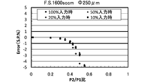
- a pore size different three kinds of pressure control type flow rate control apparatus of the orifice (F.S.130sccm, F.S.850sccm, F.S.1600sccm) pressure ratio (P 2 / P 1 ) and the set point error (SP%) are expressed using the setting input (set flow rate) to the pressure control type flow rate control device 5 as a parameter.
- the flow rate range (rated flow rate SP) is larger and the orifice hole diameter is larger, so the set point error (SP%) is zero, that is, the range of P 2 / P 1 where the critical expansion condition is satisfied is smaller. I was able to confirm.
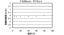
- FIG. 6 and FIG. 7 show the pressure ratio P 2 / P 1 with a set point error (SP%) within ⁇ 1% from the flow rate adjustment result obtained by the test apparatus of FIG. Between the set flow rate (%) and the flow rate linearity error (FS%) based on the control flow rate at 100% setting, that is, the set flow rate (%) and the linearity error (FS). In the range of the pressure ratio P 2 / P 1 where the critical expansion condition is satisfied, the flow rate linearity error F. S. % Is ⁇ 1% F.V. S. was found to be within.
- the present invention was created based on the results of the flow rate characteristic tests as shown in FIGS. 2 to 7, and the present inventors have established that the critical expansion condition is established as the orifice diameter of the single-hole orifice plate is smaller. Focusing on the fact that the range of the pressure ratio P 2 / P 1 is increased, when the control flow rate is increased, the orifice diameter of the single-hole orifice plate is not increased according to the flow rate width as before. By changing the number of orifices of the porous orifice plate having a hole diameter and thereby responding to the increase in the control flow rate, the range of the pressure ratio P 2 / P 1 that satisfies the critical expansion condition of the orifice circulation fluid is maximized and constant. It was conceived that the increased flow rate can be accommodated in the held state.
- an opening area of one orifice necessary for the flow of a fluid having a predetermined flow rate is divided, and a plurality of openings having a total opening area equal to the opening area are divided.
- the basic structure of the present invention is that a smaller orifice is provided.
- a second aspect of the present invention is the first aspect in which the plurality of orifices are formed by press working.
- a third aspect of the present invention is the orifice plate according to the first aspect, wherein the orifice plate has a thickness of 20 to 200 ⁇ m and is an orifice plate for a pressure control type flow control device.
- the thickness of the orifice plate is 20 to 200 ⁇ m
- the diameter of each of the plurality of orifices is 0.010 to 0.200 mm
- the number is 2 to 100.
- the vertical plane shape of the plurality of orifices is a shape composed of a rectangular portion and a trapezoidal portion.
- the back side surface of the portion of the orifice plate in which the plurality of orifices are drilled is finished by polishing.
- the ratio P 2 / P 1 between the orifice upstream pressure (P 1 ) and the orifice downstream pressure (P 2 ) satisfies the gas critical expansion condition.
- the gas flow rate Q changes in direct proportion to the gas pressure (P 1 ) on the upstream side of the orifice under the condition below the pressure ratio.
- the flow control orifice plate is the porous orifice according to any one of claims 1 to 7, To do.
- the fluid is circulated at the critical expansion conditions, the fluid flow rate Q flowing through the orifice at a flow rate control orifice plate so as directly proportional to the orifice upstream side pressure P 1, the flow of the desired fluid flow rate
- the required opening area of one orifice is divided, and a plurality of orifices having a total opening area equal to the opening area are provided.
- the control flow rate increases and the orifice opening area increases. It is held at a constant value without fluctuation, and this can effectively prevent a decrease in the control range (flow rate control range) of P 2 / P 1 .
- the flow control range can be expanded and the control accuracy can be improved.
- the plurality of orifices can be easily formed by press working, it is possible to produce an orifice plate at a lower cost than the conventional production by laser machining or the like.
- FIG. 6 is the same diagram as FIG. 5 at 850 sccm. F. S.
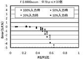
- FIG. 6 is the same diagram as FIG. 5 at 1600 sccm.
- 1 shows an example of a porous orifice plate according to the present invention. It is a top view which shows the further another example of the porous orifice plate which concerns on this invention. It is a top view which shows the further another example of the porous orifice plate which concerns on this invention.
- FIG. 11 is a relationship diagram between the pressure ratio P 2 / P 1 and the set point error (S.P.%) similar to that in FIGS. 2 to 4 when the porous orifice plate of FIG. 10 is used.
- S.P.% set point error
- FIG. 10 is a relationship diagram between a set flow rate (%) and linearity error (FS%) similar to those in FIGS. 5 to 7 when the porous orifice plate of FIG. 10 is used. It is a lineblock diagram of a publicly known pressure control type flow control device. It is a diagram which shows the flow control characteristic of the pressure control type flow control apparatus of FIG.
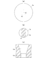
- FIG. 8 shows an example of a flow control orifice plate according to the present invention.
- FIG. 8A is a plan view
- FIG. 8B is a back view
- FIG. 8C is a cc view of FIG.
- a total of 15 orifices 12 having a hole diameter of 0.085 mm are provided on an orifice plate 7a having an outer diameter of 3.5 mm and a thickness of 0.05 mm.
- the vertical plane shape of the orifice 12 is formed by pressing into a shape comprising a rectangular portion 12a and a trapezoidal portion 12b as shown in FIG. 5C.
- the depth of the orifice 12 is the thickness of the orifice plate 7a.
- the portion provided with the orifice 12 on the back surface side of the orifice plate 7a is polished in a narrow width to form a polished surface 12c, and the front and back of the orifice plate 7a are discriminated by the polished surface 12c.
- FIG. 9 shows another example of the flow rate control porous orifice plate 7a according to the present invention, except that the number of the orifices 12 is five and the hole diameter of the orifices 12 is 0.135 mm. The other points are the same as the flow rate control porous orifice plate of FIG.
- FIG. 10 is an enlarged plan view showing still another example of a flow rate control porous orifice plate 7a according to the present invention, in which 37 orifices 12 having a hole diameter ⁇ of 79 ⁇ m (0.079 mm) are provided.
- the outer diameter, thickness, etc. of the orifice plate 7a in FIG. 10 are the same as those of the orifice plate 7a in FIGS.
- FIG. 11 shows the same relationship curve as in FIG. 2 when the porous orifice plate 7a of FIG. 10 is used in place of the single-hole orifice plate 7 in the test apparatus of FIG. 1, that is, the pressure ratio P 2. This shows the relationship with / P 1 .
- the pressure ratio P 2 / P 1 at the time of 100% input is about 0.42
- the pressure ratio P 2 / P 1 at the time of 100% input is about 0.40
- P 2 / P that satisfies the critical expansion condition is satisfied. It can be seen that the range of 1 can be widened. Note that there is a slight difference as described above between the pressure ratio P 2 / P 1 at which the theoretical critical expansion condition is satisfied and the pressure ratio P 2 / P 1 at which the critical expansion condition is obtained in actual measurement. The reason why this occurs is theoretically unanalyzed and currently under consideration, but it is assumed that the difference in the flow state of the fluid on the orifice outlet side has an effect.
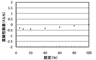
- FIG. 12 is the same diagram as FIG. 5 when the porous orifice plate 7a of the present invention is used, and the pressure ratio P 2 / P with a set point error (SP%) within ⁇ 1%.
- 1 is a diagram showing the relationship between a set flow rate (%) in 1 and an error (flow linearity error) (FS%) with respect to a control flow rate when 100% is set.
- the flow linearity error (FS%) is ⁇ 1% F.S. for the porous orifice plate 7a of the present invention. S. Has been confirmed to be within.
- the pressure control type flow control device includes the orifice plate of the F180 type pressure control type flow control device manufactured by Fujikin Co., Ltd. or the pressure control type flow control device shown in FIG. It is converted into a plate. Therefore, the detailed description is abbreviate
- the porous orifice plate for flow control according to the present invention and the pressure control type flow control device using the same are adjusted by adjusting the number of orifices 12 according to the control flow, so that the control flow becomes large.
- the range of the pressure ratio P 2 / P 1 where the critical expansion condition is satisfied can be kept wide and constant, whereby highly accurate flow rate control can be stably performed over a wide range.
- porous orifice plate according to the present invention can be applied not only to a pressure-controlled flow rate control device but also to any orifice such as an orifice device or a fluid diversion device that is inserted into a normal pipe line to control a fluid flow rate. Is.
Landscapes
- Engineering & Computer Science (AREA)
- General Engineering & Computer Science (AREA)
- Physics & Mathematics (AREA)
- Mechanical Engineering (AREA)
- General Physics & Mathematics (AREA)
- Automation & Control Theory (AREA)
- Flow Control (AREA)
- Fluid Mechanics (AREA)
Abstract
Description
図13は、本発明者等が先に公開したオリフィスを用いた圧力制御式流量制御装置の構成一例を示すものであり、当該流量制御装置21はコントロール弁22、圧力検出器23、温度検出器24、オリフィス25、演算制御装置26、増幅器27a、27b、A/D変換28a・28b等から形成されている(特開平8-338546号)。
また、コントロール弁22は、制御信号Qyによって両者の差Qc-Qsが零になる方向に開閉制御され、これによりオリフィス25の下流側の流量が設定流量(流量指令値)Qsに常時保持される。
この図14からも明らかなように、上流側圧力P1が下流側圧力P2の約2倍を越える範囲に於いては、流量QcとP1とはリニアな関係に保持され、Qcはオリフィス上流側の圧力P1に正比例することになり、オリフィス上流側圧力P1を自動制御することにより、オリフィスを流通する流量のフィードバック制御を行うことができる。尚、図14に於いて、Aはオリフィスの孔径が0.37mmφ、Bは0.20φの場合の流量制御特性を示すものである。
尚、流量測定は、圧力制御式流量制御装置5の設定流量の100%、50%、20%及び10%の夫々について行った。
その結果、臨界膨張条件が成立するオリフィス上流側圧力P1と下流側圧力P2との圧力比P2/P1が、制御流量が増大してオリフィスの開口面積が大きくなっても、現実に変動することなく一定の値に保持されることになり、これによりP2/P1の制御範囲(流量制御範囲)の減少を有効に防止することができる。また、当該オリフィスプレートを用いた圧力制御式流量制御装置にあっては、流量制御範囲の拡大と制御精度の向上が可能となる。
図8は本発明に係る流量制御用オリフィスプレートの一例を示すものであり、(a)は平面図、(b)は裏面図、(c)は(b)のc-c視図である。
また、前記オリフィス12の縦断平面形状は、(c)に示すように長方形部12aと台形部12bとから成る形状にプレス加工により形成されており、オリフィス12の深さはオリフィスプレート7aの厚さ0.05mmと同一寸法である。
更に、オリフィスプレート7aの裏面側のオリフィス12を設けた部分は、細幅状に研磨され、研磨面12cが形成されており、当該研磨面12cによりオリフィスプレート7aの表裏が判別される。
尚図10のオリフィスプレート7aの外径、厚さ等は前記図8及び図9のオリフィスプレート7aと同一である。
従って、図10の流量制御用多孔型オリフィスプレート7aは、180sccm×37=6.660sccmのF.S.流量に相当する。
図12からも明らかなように、本発明の多孔型オリフィスプレート7aについても流量直線性誤差(F.S.%)は±1%F.S.以内になることが確認されている。
2 圧力調整器
3 圧力計
4 モルブロック流量測定器
5 圧力式流量制御装置
6 コントロール弁
7 オリフィスプレート(単孔型)
7a 多孔型オリフィスプレート
8 オリフィス上流側圧力検出器
9 オリフィス下流側圧力検出器
10 オリフィス下流側圧力P2の調整弁
11 真空排気ポンプ
P1 オリフィス上流側圧力
P2 オリフィス下流側圧力
Po ガス供給源側圧力
12 オリフィス
Claims (8)
- 流体の流量制御用オリフィスプレートに於いて、所定流量の流体の流通に必要な一つのオリフィスの開口面積を分割し、前記開口面積に等しい総開口面積を有する複数のオリフィスを設けた構成としたことを特徴とする流量制御用多孔型オリフィスプレート。
- 前記複数のオリフィスをプレス加工により形成するようにした請求項1に記載の流量制御用多孔型オリフィスプレート。
- 前記オリフィスプレートの厚さを20~200μmとすると共に、圧力制御式流量制御装置用のオリフィスプレートとした請求項1に記載の流量制御用多孔型オリフィスプレート。
- 前記オリフィスプレートの厚さを20~200μm、前記複数のオリフィスの各々の口径を0.010~0.200mm、前記複数のオリフィスの数を2~100個とした請求項1に記載の流量制御用多孔型オリフィスプレート。
- 前記複数のオリフィスの各々の縦断平面形状を長方形部分と台形部分とからなる形状とした請求項1に記載の流量制御用多孔型オリフィスプレート。
- 前記オリフィスプレートの前記複数のオリフィスを穿設した部分の裏側面を研磨により仕上げした構成とした請求項5に記載の流量制御用多孔型オリフィスプレート。
- オリフィス上流側圧力(P1)とオリフィス下流側圧力(P2)の比P2/P1が、気体の臨界膨張条件が成立する圧力比以下の条件において、気体の流量がオリフィス上流側の気体圧力(P1)に正比例して変化することを特徴とする請求項1に記載の流量制御用多孔型オリフィスプレート。
- オリフィスプレートを用いた圧力制御式流量制御装置において、前記オリフィスプレートを請求項1乃至請求項7の何れかに記載の流量制御用多孔型オリフィスプレートとしたことを特徴とする圧力制御式流量制御装置。
Priority Applications (3)
| Application Number | Priority Date | Filing Date | Title |
|---|---|---|---|
| CN201480004462.9A CN105102872B (zh) | 2013-04-25 | 2014-04-09 | 流量控制用的多孔型孔板及使用该孔板的流量控制装置 |
| KR1020157018586A KR20150095824A (ko) | 2013-04-25 | 2014-04-09 | 유량 제어용 다공형 오리피스 플레이트 및 이것을 사용한 유량 제어 장치 |
| US14/785,789 US9746856B2 (en) | 2013-04-25 | 2014-04-09 | Multi-hole orifice plate for flow control, and flow controller using the same |
Applications Claiming Priority (2)
| Application Number | Priority Date | Filing Date | Title |
|---|---|---|---|
| JP2013091867A JP6306286B2 (ja) | 2013-04-25 | 2013-04-25 | 流量制御用のオリフィスプレート及びこれを用いた圧力式流量制御装置 |
| JP2013-091867 | 2013-04-25 |
Publications (1)
| Publication Number | Publication Date |
|---|---|
| WO2014174782A1 true WO2014174782A1 (ja) | 2014-10-30 |
Family
ID=51791371
Family Applications (1)
| Application Number | Title | Priority Date | Filing Date |
|---|---|---|---|
| PCT/JP2014/002041 WO2014174782A1 (ja) | 2013-04-25 | 2014-04-09 | 流量制御用の多孔型オリフィスプレート及びこれを用いた流量制御装置 |
Country Status (6)
| Country | Link |
|---|---|
| US (1) | US9746856B2 (ja) |
| JP (1) | JP6306286B2 (ja) |
| KR (1) | KR20150095824A (ja) |
| CN (1) | CN105102872B (ja) |
| TW (1) | TWI534575B (ja) |
| WO (1) | WO2014174782A1 (ja) |
Cited By (1)
| Publication number | Priority date | Publication date | Assignee | Title |
|---|---|---|---|---|
| JP6295385B1 (ja) * | 2017-04-07 | 2018-03-14 | 清 高浦 | エアーシリンダ排気室内の圧縮空気圧安定装置 |
Families Citing this family (3)
| Publication number | Priority date | Publication date | Assignee | Title |
|---|---|---|---|---|
| KR101673139B1 (ko) * | 2014-04-15 | 2016-11-22 | 이여형 | 벤츄리 구조의 단면을 가지는 메쉬 타공망을 이용한 용존관 |
| US10386864B2 (en) * | 2016-04-12 | 2019-08-20 | Hitachi Metals, Ltd. | Mass flow controller and a method for controlling a mass flow rate |
| US11199861B2 (en) * | 2021-03-26 | 2021-12-14 | CleanNesta LLC | Integrated variable pressure and flow regulator |
Citations (10)
| Publication number | Priority date | Publication date | Assignee | Title |
|---|---|---|---|---|
| JPH02178927A (ja) * | 1988-12-29 | 1990-07-11 | Hitachi Ltd | 板面体の研磨方法 |
| JPH052215U (ja) * | 1991-06-24 | 1993-01-14 | 株式会社クボタ | 多孔可変オリフイス弁の制御装置 |
| JP2000020136A (ja) * | 1998-06-30 | 2000-01-21 | Yamatake Corp | 流量計測装置及び流量制御装置 |
| JP2001179136A (ja) * | 1999-12-27 | 2001-07-03 | Optonix Seimitsu:Kk | オリフィスプレートの製造方法 |
| JP2002213642A (ja) * | 2001-01-16 | 2002-07-31 | Neriki:Kk | 流量調整装置 |
| JP2004199109A (ja) * | 2002-12-16 | 2004-07-15 | Fujikin Inc | 圧力式流量制御装置を用いた流体の流量制御方法 |
| JP2005021420A (ja) * | 2003-07-03 | 2005-01-27 | Dentsply Sankin Kk | 骨接合用プレート |
| JP2005149075A (ja) * | 2003-11-14 | 2005-06-09 | Fujikin Inc | 流体制御装置 |
| JP2011185183A (ja) * | 2010-03-09 | 2011-09-22 | Hitachi Automotive Systems Ltd | オリフィス加工方法 |
| WO2013046517A1 (ja) * | 2011-09-30 | 2013-04-04 | 株式会社フジキン | 気化器 |
Family Cites Families (19)
| Publication number | Priority date | Publication date | Assignee | Title |
|---|---|---|---|---|
| US1330174A (en) * | 1918-05-17 | 1920-02-10 | Cew Judson A De | Method and apparatus for emulsifying oil solutions and the like |
| US1398063A (en) * | 1919-05-16 | 1921-11-22 | Clifford C Brown | Mixer for gas-engines |
| US1503371A (en) * | 1923-07-23 | 1924-07-29 | Joseph P Meyer | Attachment for gas engines |
| US1515408A (en) * | 1924-05-12 | 1924-11-11 | Edmund W Puffer | Fuel and air mixer |
| US1797954A (en) * | 1929-04-22 | 1931-03-24 | Thomas C Whitehead | Refrigerant control |
| FR690214A (fr) * | 1929-06-04 | 1930-09-17 | Glanzstoff Ag | Tuyère pour la production de la soie artificielle et en particulier pour la soie deviscose |
| CA2063820C (en) * | 1989-07-20 | 1998-08-04 | Elizabeth M. Laws | Flow conditioner |
| US5295397A (en) * | 1991-07-15 | 1994-03-22 | The Texas A & M University System | Slotted orifice flowmeter |
| US5461932A (en) * | 1991-07-15 | 1995-10-31 | Texas A & M University System | Slotted orifice flowmeter |
| US5327941A (en) * | 1992-06-16 | 1994-07-12 | The United States Of America As Represented By The Secretary Of The Navy | Cascade orificial resistive device |
| US5918637A (en) * | 1993-08-16 | 1999-07-06 | Fleischman; William H. | Plates perforated with venturi-like orifices |
| JP3291161B2 (ja) | 1995-06-12 | 2002-06-10 | 株式会社フジキン | 圧力式流量制御装置 |
| JP3686748B2 (ja) | 1997-08-15 | 2005-08-24 | 忠弘 大見 | 圧力式流量制御装置用オリフィス及びその製造方法 |
| US6186179B1 (en) * | 1998-09-18 | 2001-02-13 | Panametrics, Inc. | Disturbance simulating flow plate |
| US7300038B2 (en) * | 2002-07-23 | 2007-11-27 | Advanced Technology Materials, Inc. | Method and apparatus to help promote contact of gas with vaporized material |
| US7051765B1 (en) * | 2003-12-19 | 2006-05-30 | The United States Of America As Represented By The Administrator Of The National Aeronautics And Space Administration | Balanced orifice plate |
| US20050150155A1 (en) * | 2004-01-09 | 2005-07-14 | Clean Fuels Technology, Inc., A Nevada Corporation. | Mixing apparatus and method for manufacturing an emulsified fuel |
| US8724974B2 (en) | 2011-09-30 | 2014-05-13 | Fujikin Incorporated | Vaporizer |
| US9200650B2 (en) * | 2013-09-26 | 2015-12-01 | Paul D. Van Buskirk | Orifice plates |
-
2013
- 2013-04-25 JP JP2013091867A patent/JP6306286B2/ja active Active
-
2014
- 2014-04-09 CN CN201480004462.9A patent/CN105102872B/zh not_active Expired - Fee Related
- 2014-04-09 WO PCT/JP2014/002041 patent/WO2014174782A1/ja active Application Filing
- 2014-04-09 KR KR1020157018586A patent/KR20150095824A/ko active Search and Examination
- 2014-04-09 US US14/785,789 patent/US9746856B2/en active Active
- 2014-04-21 TW TW103114392A patent/TWI534575B/zh active
Patent Citations (10)
| Publication number | Priority date | Publication date | Assignee | Title |
|---|---|---|---|---|
| JPH02178927A (ja) * | 1988-12-29 | 1990-07-11 | Hitachi Ltd | 板面体の研磨方法 |
| JPH052215U (ja) * | 1991-06-24 | 1993-01-14 | 株式会社クボタ | 多孔可変オリフイス弁の制御装置 |
| JP2000020136A (ja) * | 1998-06-30 | 2000-01-21 | Yamatake Corp | 流量計測装置及び流量制御装置 |
| JP2001179136A (ja) * | 1999-12-27 | 2001-07-03 | Optonix Seimitsu:Kk | オリフィスプレートの製造方法 |
| JP2002213642A (ja) * | 2001-01-16 | 2002-07-31 | Neriki:Kk | 流量調整装置 |
| JP2004199109A (ja) * | 2002-12-16 | 2004-07-15 | Fujikin Inc | 圧力式流量制御装置を用いた流体の流量制御方法 |
| JP2005021420A (ja) * | 2003-07-03 | 2005-01-27 | Dentsply Sankin Kk | 骨接合用プレート |
| JP2005149075A (ja) * | 2003-11-14 | 2005-06-09 | Fujikin Inc | 流体制御装置 |
| JP2011185183A (ja) * | 2010-03-09 | 2011-09-22 | Hitachi Automotive Systems Ltd | オリフィス加工方法 |
| WO2013046517A1 (ja) * | 2011-09-30 | 2013-04-04 | 株式会社フジキン | 気化器 |
Cited By (2)
| Publication number | Priority date | Publication date | Assignee | Title |
|---|---|---|---|---|
| JP6295385B1 (ja) * | 2017-04-07 | 2018-03-14 | 清 高浦 | エアーシリンダ排気室内の圧縮空気圧安定装置 |
| JP2018179277A (ja) * | 2017-04-07 | 2018-11-15 | 清 高浦 | エアーシリンダ排気室内の圧縮空気圧安定装置 |
Also Published As
| Publication number | Publication date |
|---|---|
| TW201512799A (zh) | 2015-04-01 |
| KR20150095824A (ko) | 2015-08-21 |
| TWI534575B (zh) | 2016-05-21 |
| CN105102872A (zh) | 2015-11-25 |
| CN105102872B (zh) | 2017-04-05 |
| US20160070271A1 (en) | 2016-03-10 |
| JP6306286B2 (ja) | 2018-04-04 |
| JP2014215782A (ja) | 2014-11-17 |
| US9746856B2 (en) | 2017-08-29 |
Similar Documents
| Publication | Publication Date | Title |
|---|---|---|
| WO2014174782A1 (ja) | 流量制御用の多孔型オリフィスプレート及びこれを用いた流量制御装置 | |
| KR100525353B1 (ko) | 진공반응로내의 가스흐름 모니터 방법 및 진공처리배치 | |
| JP4585035B2 (ja) | 流量比率制御装置 | |
| TWI386770B (zh) | And a discontinuous flow rate switching control method using a fluid of the pressure type flow control device | |
| EP2089679B1 (en) | Controller gain scheduling for mass flow controllers | |
| JP5809012B2 (ja) | 流量制御装置、流量測定機構、又は、当該流量測定機構を備えた流量制御装置に用いられる診断装置及び診断用プログラム | |
| US20090095068A1 (en) | System for and method of providing a wide-range flow controller | |
| TWI642910B (zh) | 流量控制機器、流量控制機器的流量校正方法、流量測定機器及使用流量測定機器的流量測定方法 | |
| EP1879004B1 (en) | Flow rate measuring device | |
| JP2014215782A5 (ja) | ||
| CN103900646A (zh) | 流量运算装置以及流量控制装置 | |
| KR20130040740A (ko) | 유량 제어 장치, 유량 측정 기구, 또는 당해 유량 측정 기구를 구비한 유량 제어 장치에 이용되는 진단 장치 및 진단용 프로그램이 기록된 기록 매체 | |
| CN101484858A (zh) | 流量控制阀的控制方法和控制系统 | |
| JP2010519648A (ja) | マルチ反対称最適制御性能構成を使用する流量比制御装置を含むガス送出方法及びシステム | |
| JP2012033188A (ja) | 流量レンジ可変型流量制御装置 | |
| KR20190016572A (ko) | 유체 제어 장치 | |
| JP2022047815A (ja) | マスフローコントローラ | |
| CN113155207A (zh) | 差压式流量计 | |
| US10605636B2 (en) | Flowmeter | |
| US20110155259A1 (en) | Control arrangement having a pressure limiting valve | |
| TW201736746A (zh) | 節流單元、設有該節流單元的靜壓軸承裝置及附設溝槽的塊體之製造方法 | |
| JP2018096848A (ja) | 流量特性関数同定方法、流量特性関数同定装置、流量特性関数同定用プログラム、及び、これらを用いた流量センサ又は流量制御装置 | |
| KR101958289B1 (ko) | 유량계 일체형 밸브 | |
| KR20190068817A (ko) | 외부 제어기기와 통신할 수 있는 질량 유량 최적화 제어 시스템 | |
| US20220107212A1 (en) | Differential-pressure-based flow meters |
Legal Events
| Date | Code | Title | Description |
|---|---|---|---|
| WWE | Wipo information: entry into national phase |
Ref document number: 201480004462.9 Country of ref document: CN |
|
| 121 | Ep: the epo has been informed by wipo that ep was designated in this application |
Ref document number: 14788496 Country of ref document: EP Kind code of ref document: A1 |
|
| ENP | Entry into the national phase |
Ref document number: 20157018586 Country of ref document: KR Kind code of ref document: A |
|
| WWE | Wipo information: entry into national phase |
Ref document number: 14785789 Country of ref document: US |
|
| NENP | Non-entry into the national phase |
Ref country code: DE |
|
| 122 | Ep: pct application non-entry in european phase |
Ref document number: 14788496 Country of ref document: EP Kind code of ref document: A1 |