WO2014168017A1 - 車両の制御装置および車両の制御方法 - Google Patents
車両の制御装置および車両の制御方法 Download PDFInfo
- Publication number
- WO2014168017A1 WO2014168017A1 PCT/JP2014/058908 JP2014058908W WO2014168017A1 WO 2014168017 A1 WO2014168017 A1 WO 2014168017A1 JP 2014058908 W JP2014058908 W JP 2014058908W WO 2014168017 A1 WO2014168017 A1 WO 2014168017A1
- Authority
- WO
- WIPO (PCT)
- Prior art keywords
- engine
- remaining capacity
- battery remaining
- target
- time
- Prior art date
- Legal status (The legal status is an assumption and is not a legal conclusion. Google has not performed a legal analysis and makes no representation as to the accuracy of the status listed.)
- Ceased
Links
Images









Classifications
-
- F—MECHANICAL ENGINEERING; LIGHTING; HEATING; WEAPONS; BLASTING
- F02—COMBUSTION ENGINES; HOT-GAS OR COMBUSTION-PRODUCT ENGINE PLANTS
- F02D—CONTROLLING COMBUSTION ENGINES
- F02D17/00—Controlling engines by cutting out individual cylinders; Rendering engines inoperative or idling
- F02D17/04—Controlling engines by cutting out individual cylinders; Rendering engines inoperative or idling rendering engines inoperative or idling, e.g. caused by abnormal conditions
-
- F—MECHANICAL ENGINEERING; LIGHTING; HEATING; WEAPONS; BLASTING
- F02—COMBUSTION ENGINES; HOT-GAS OR COMBUSTION-PRODUCT ENGINE PLANTS
- F02D—CONTROLLING COMBUSTION ENGINES
- F02D29/00—Controlling engines, such controlling being peculiar to the devices driven thereby, the devices being other than parts or accessories essential to engine operation, e.g. controlling of engines by signals external thereto
- F02D29/02—Controlling engines, such controlling being peculiar to the devices driven thereby, the devices being other than parts or accessories essential to engine operation, e.g. controlling of engines by signals external thereto peculiar to engines driving vehicles; peculiar to engines driving variable pitch propellers
-
- F—MECHANICAL ENGINEERING; LIGHTING; HEATING; WEAPONS; BLASTING
- F02—COMBUSTION ENGINES; HOT-GAS OR COMBUSTION-PRODUCT ENGINE PLANTS
- F02N—STARTING OF COMBUSTION ENGINES; STARTING AIDS FOR SUCH ENGINES, NOT OTHERWISE PROVIDED FOR
- F02N11/00—Starting of engines by means of electric motors
- F02N11/08—Circuits specially adapted for starting of engines
- F02N11/0814—Circuits specially adapted for starting of engines comprising means for controlling automatic idle-start-stop
- F02N11/0818—Conditions for starting or stopping the engine or for deactivating the idle-start-stop mode
- F02N11/0825—Conditions for starting or stopping the engine or for deactivating the idle-start-stop mode related to prevention of engine restart failure, e.g. disabling automatic stop at low battery state
-
- F—MECHANICAL ENGINEERING; LIGHTING; HEATING; WEAPONS; BLASTING
- F02—COMBUSTION ENGINES; HOT-GAS OR COMBUSTION-PRODUCT ENGINE PLANTS
- F02N—STARTING OF COMBUSTION ENGINES; STARTING AIDS FOR SUCH ENGINES, NOT OTHERWISE PROVIDED FOR
- F02N2200/00—Parameters used for control of starting apparatus
- F02N2200/06—Parameters used for control of starting apparatus said parameters being related to the power supply or driving circuits for the starter
- F02N2200/061—Battery state of charge [SOC]
-
- F—MECHANICAL ENGINEERING; LIGHTING; HEATING; WEAPONS; BLASTING
- F02—COMBUSTION ENGINES; HOT-GAS OR COMBUSTION-PRODUCT ENGINE PLANTS
- F02N—STARTING OF COMBUSTION ENGINES; STARTING AIDS FOR SUCH ENGINES, NOT OTHERWISE PROVIDED FOR
- F02N2200/00—Parameters used for control of starting apparatus
- F02N2200/06—Parameters used for control of starting apparatus said parameters being related to the power supply or driving circuits for the starter
- F02N2200/063—Battery voltage
-
- Y—GENERAL TAGGING OF NEW TECHNOLOGICAL DEVELOPMENTS; GENERAL TAGGING OF CROSS-SECTIONAL TECHNOLOGIES SPANNING OVER SEVERAL SECTIONS OF THE IPC; TECHNICAL SUBJECTS COVERED BY FORMER USPC CROSS-REFERENCE ART COLLECTIONS [XRACs] AND DIGESTS
- Y02—TECHNOLOGIES OR APPLICATIONS FOR MITIGATION OR ADAPTATION AGAINST CLIMATE CHANGE
- Y02T—CLIMATE CHANGE MITIGATION TECHNOLOGIES RELATED TO TRANSPORTATION
- Y02T10/00—Road transport of goods or passengers
- Y02T10/10—Internal combustion engine [ICE] based vehicles
- Y02T10/40—Engine management systems
Definitions
- the present invention relates to vehicle control, particularly to battery charge control for effectively utilizing automatic engine stop.
- the automatic stop may be prohibited when the voltage is lower than a predetermined voltage. If automatic stop is prohibited, engine fuel efficiency cannot be improved.
- the object of the present invention is to provide a technique in which the automatic stop of the engine is hardly prohibited even when the engine is started for the first time after moving to a cold area from the point where the engine was first started.
- the vehicle control apparatus includes an automatic stop / automatic stop that can automatically stop the engine and restart the engine according to the operating state of the engine after the initial engine start in response to the ignition key ON operation.
- Restart execution means automatic stop prohibiting means for prohibiting the automatic stop of the engine when the minimum voltage of the battery that is reduced by cranking at the first engine start falls below a predetermined voltage, and a target battery remaining capacity for setting a target battery remaining capacity Capacity setting means, and charge control means for performing charge control of the battery based on the target battery remaining capacity and the actual battery remaining capacity.
- the target battery remaining capacity setting means is configured to use the target battery remaining capacity for the first engine start when the vehicle moves to a colder region from the point of the first engine start between the ignition key ON operation and the ignition key OFF operation. Make it bigger than time.
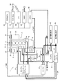
- FIG. 1 is a schematic configuration diagram of a vehicle on which the vehicle control device according to the first embodiment is mounted.
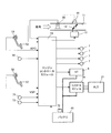
- FIG. 2 is a control system diagram of the gasoline engine.
- FIG. 3 is a timing chart of a comparative example showing how each parameter changes when moving to a colder area than the key start point.
- FIG. 4 is a timing chart of the first embodiment showing how each parameter changes when moving to a colder area than the key start point.
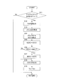
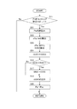
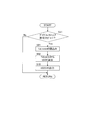
- FIG. 5 is a flowchart for explaining battery determination at key start.
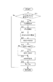
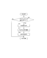
- FIG. 6 is a flowchart for explaining setting of the target battery remaining capacity according to the first embodiment.
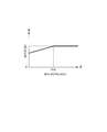
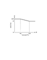
- FIG. 7 is a characteristic diagram of the target battery remaining capacity with respect to the amount of change of the outside air temperature per predetermined time according to the first embodiment.
- FIG. 8 is a flowchart for explaining setting of the target battery remaining capacity according to the second embodiment.
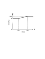
- FIG. 9 is a characteristic diagram of the target battery remaining capacity with respect to the temperature difference of the outside air temperature for each predetermined time according to the second embodiment.
- FIG. 10 is a flowchart for explaining setting of the target battery remaining capacity according to the third embodiment.
- FIG. 11 is a characteristic diagram of the target battery remaining capacity with respect to the outside air temperature according to the third embodiment.
- FIG. 12 is a flowchart for explaining setting of the target battery remaining capacity according to the fourth embodiment.
- FIG. 13 is a characteristic diagram of the target battery remaining capacity with respect to the amount of change in atmospheric pressure per predetermined time according to the fourth embodiment.
- FIG. 14 is a flowchart for explaining setting of the target battery remaining capacity according to the fifth embodiment.
- FIG. 15 is a characteristic diagram of the target battery remaining capacity with respect to the pressure difference at predetermined time intervals in the atmospheric pressure according to the fifth embodiment.
- FIG. 16 is a flowchart for explaining setting of the target battery remaining capacity according to the sixth embodiment.
- FIG. 17 is a characteristic diagram of the target battery remaining capacity with respect to the atmospheric pressure according to the sixth embodiment.
- FIG. 18 is a flowchart for explaining setting of the target battery remaining capacity according to the seventh embodiment.
- FIG. 19 is a characteristic diagram of the target battery remaining capacity with respect to the altitude data of the seventh embodiment.
- FIG. 20 is a flowchart for explaining setting of the target battery remaining capacity according to the eighth embodiment.
- FIG. 21 is a characteristic diagram of the target battery remaining capacity with respect to the predicted minimum temperature at the destination according to the eighth embodiment.
- FIG. 1 is a schematic configuration diagram of a vehicle 1 on which a vehicle control device according to the first embodiment is mounted.
- a vehicle 1 includes an engine 2, an alternator (ALT in the figure) 21, and an air conditioner compressor 31.
- the output shaft 3 of the engine 2, the rotating shaft 22 of the alternator 21, and the rotating shaft 32 of the air conditioner compressor 31 are arranged in parallel.
- the crank pulley 4 is attached to one end of the output shaft 3, and the pulleys 23 and 33 are attached to the rotary shafts 22 and 32, respectively.
- a belt 5 is wound around each of the three pulleys 4, 23, and 33, and power is transmitted (conducted) between the output shaft 3 and the rotary shafts 23 and 33 of the engine 2 by the belt 5.
- a starter (ST in the figure) 6 is provided to start the engine 2.
- a torque converter 8 and a belt type automatic transmission 9 are connected to the other end of the output shaft 3 of the engine 2.
- the torque converter 8 has a pump impeller and a turbine runner (not shown).
- the belt-type automatic transmission 9 includes a primary pulley and a secondary pulley (not shown) and a steel belt that is wound around these pulleys.
- the rotational driving force of the engine 2 is finally transmitted to vehicle driving wheels (not shown) via the torque converter 8 and the automatic transmission 9.
- a 14V battery 41 is provided as a power source of the vehicle 1.
- the electric power generated by the operation of the alternator 21 is stored in the battery 41.
- the battery 41 is directly connected to the starter 6, the first electric load 43, and the alternator 21.
- the first electric load 43 is, for example, an airbag.
- a second electrical load 45 is connected to the battery 41 via a DC-DC converter 42.
- the second electrical load 45 is, for example, an audio system that is vulnerable to an instantaneous drop in battery voltage.
- the second electrical load 45 is connected via the DC-DC converter 42 for the following reason. That is, since the battery voltage temporarily decreases during cranking when the engine is restarted, the operation of the second electric load 45 is affected by the temporary decrease of the battery. Therefore, during the cranking, the DC-DC converter 42 is operated to boost the voltage of the battery 41 that temporarily decreases, thereby suppressing the supply voltage to the second electric load 45 from decreasing instantaneously.
- the DC-DC converter 42 and the engine control module 51 are connected by a LIN (Local Interconnect Network), and the operation / non-operation of the DC-DC converter 42 is controlled by the engine control module 51.
- LIN Local Interconnect Network
- the engine control module 51 controls the engine 2, the starter 6, and the alternator 21.
- FIG. 2 is a control system diagram of the gasoline engine.
- Each intake port (not shown) is provided with a fuel injection valve 7.
- the fuel injection valve 7 intermittently supplies fuel to the engine 2.
- An electronically controlled throttle valve 12 is provided in the intake passage 11.
- the opening of the throttle valve 12 (hereinafter referred to as “throttle opening”) is controlled by a throttle motor 13.
- the actual throttle opening is detected by the throttle sensor 14 and input to the engine control module 51.
- the engine control module 51 receives an accelerator opening signal (amount of depression of the accelerator pedal 52) from the accelerator sensor 53, a crank angle signal from the crank angle sensor 54, and an intake air amount signal from the air flow meter 55. ing. From the signal of the crank angle sensor 54, the rotational speed of the engine 2 is calculated. The engine control module 51 calculates a target intake air amount and a target fuel injection amount based on these signals, and applies the throttle motor 13 and each fuel injection valve 7 to obtain the target intake air amount and the target fuel injection amount. Issue a command.
- an accelerator opening signal amount of depression of the accelerator pedal 52
- crank angle sensor 54 From the signal of the crank angle sensor 54, the rotational speed of the engine 2 is calculated.
- the engine control module 51 calculates a target intake air amount and a target fuel injection amount based on these signals, and applies the throttle motor 13 and each fuel injection valve 7 to obtain the target intake air amount and the target fuel injection amount. Issue a command.
- the gasoline engine 2 has a spark plug facing the combustion chamber (cylinder).
- the engine control module 51 generates a spark in the spark plug by cutting off the primary current of the ignition coil at a predetermined time before the compression top dead center, thereby igniting the air-fuel mixture in the combustion chamber.
- the engine control module 51 drives the starter 6 to start the engine 2 when it is determined that there is a first start request based on the ON operation of the ignition key 71 by the driver.
- the vehicle 1 includes an automatic transmission control unit (CVTCU in the figure) 61.
- the automatic transmission control unit 61 controls the gear ratio of the automatic transmission 9 in a stepless manner according to the vehicle running conditions determined from the vehicle speed and the throttle opening.
- the torque converter 8 having a pump impeller and a turbine runner is provided with a mechanical lockup clutch for fastening and releasing the pump impeller and the turbine runner.
- the travel range of the vehicle that engages the lockup clutch is predetermined as a lockup region (vehicle speed and throttle opening are used as parameters).
- the automatic transmission control unit 61 engages the lockup clutch to directly connect the engine 2 and the transmission 9 when the vehicle driving condition is in the lockup region, so that the vehicle driving condition is in the lockup region. When not, release the lock-up clutch. When the engine 2 and the transmission 9 are in a directly connected state, the torque converter 8 does not absorb the torque, and the fuel efficiency is improved accordingly.
- the vehicle 1 also includes another control unit 62, an air conditioner auto-amplifier (A / C AMP) 63, an ITS 64, a navigation system (NAVI in the figure) 65, and an IPDM (Intelligent Power Distribution Module) 66.
- ITS Intelligent Transport System
- the ITS 64 acquires the weather data 69.
- the navigation system 65 inputs a signal from GPS (Global Positioning System), a signal from a vehicle speed sensor, a signal from a gyro, and a signal from an acceleration sensor, and calculates the current position of the vehicle at a constant cycle.
- GPS Global Positioning System
- the signal from the GPS includes altitude data of the current position of the vehicle.
- the two control units 61, 62, ITS64, and NAVI65 are electric loads that cannot tolerate a voltage drop. Therefore, they are supplied with power via the DC-DC converter 42.
- the engine control module 51 and the two control units 61 and 62, the air conditioner auto-amplifier 63, the ITS 64, the NAVI 65, and the IPDM 66 are connected by CAN (Controller-Area-Network).
- the charge / discharge current of the battery 41 is detected by the current sensor 67 and input to the engine control module 51 via the IPDM 66.
- the engine control module 51 (target battery remaining capacity setting means) sets the target battery remaining capacity tSOC (State Of Charge) in accordance with the operating conditions of the engine 2 and the charge / discharge current of the battery 41 at regular time intervals. Based on the integrated value, the actual remaining battery capacity rSOC is calculated.
- the balance of charge / discharge of the battery 41 is managed based on the target remaining battery capacity tSOC and the actual remaining battery capacity rSOC. For example, when the actual battery remaining capacity rSOC is less than the target battery remaining capacity tSOC, the engine control module 51 increases the target power generation voltage of the alternator 21.
- the control module 24 (see FIG. 2) (charging control means) variably controls the target power generation voltage of the alternator 21 so that this target power generation voltage is obtained.
- the starter 6 cranks the engine 2 in response to power supply from the battery 41.
- the battery voltage temporarily decreases.
- the minimum value of the battery voltage that temporarily decreases that is, the minimum battery voltage
- the actual remaining battery capacity rSOC the minimum battery voltage
- the engine control module 51 (automatic stop prohibiting means) detects the minimum battery voltage when the engine is started for the first time, and prohibits idle stop when the detected minimum battery voltage is lower than the predetermined voltage Va.
- the reason for prohibiting the idle stop is that when cranking from the idle stop, the system voltage may drop below the predetermined voltage Va and the first electric load 43 may be reset. That is, if the battery minimum voltage is less than the predetermined voltage Va, the merchantability is significantly impaired.
- the initial engine start based on the ON operation of the ignition key 71 is also referred to as “key start” in order to distinguish it from engine restart (engine start) by releasing the idle stop.
- the first engine start based on the ON operation of the ignition key 71 is also simply referred to as “first engine start”.
- the outside air temperature is 10 ° C. at home in a lowland and not a cold region.
- the outside air temperature drops to -5 ° C, the ignition at the timing of t4
- the engine is stopped by the key OFF operation.
- the outdoor temperature of the ski resort is as low as -5 ° C.
- the target battery remaining capacity tSOC is not normally set to 100% corresponding to the fully charged state by the regenerative control by the alternator 21, but 100% Generally, it is set to a lower value, for example, about 85%.
- the value of 85% is determined as follows. That is, the smaller the target battery remaining capacity is, the better, in order to recover the electric power by the regenerative control by the alternator 21.
- the larger the target remaining battery capacity of the battery 41 as the power source the better. That is, 85% is selected because it is necessary to leave a margin for charging while responding to a request for the battery 41 as a power source.
- the target remaining battery capacity tSOC is 85% because the battery 41 still has 15% of the chargeable allowance, and even if there is remaining charge capacity, the skiing starts without using this remaining charge capacity. Therefore, idle stop is prohibited. In other words, even if the target remaining battery capacity of 85% is appropriate as long as the target is around room temperature, if the target remaining battery capacity is 85% until the key start at the ski resort, the remaining charge capacity of the battery 41 The idle stop is prohibited unnecessarily while leaving In other words, there is an opportunity to improve fuel efficiency when the vehicle is running after starting the key at the ski resort.
- the target battery remaining capacity tSOC is set to the key. Make it larger than at startup. This will be specifically described with reference to FIG.
- FIG. 4 shows a case where the vehicle is run under the same situation as in FIG. 3, and when the control by the vehicle control device in the first embodiment is performed, the outside air temperature, the atmospheric pressure, the idle stop permission signal, the key It is a figure which shows what happens to each parameter, such as a battery minimum voltage at the time of starting, a target battery remaining capacity, an actual battery remaining capacity, a battery charging voltage.
- the outside air temperature decreases from the point at the time of key start at home during the period from the timing t2 when the vehicle starts moving on the uphill road to the timing t3, and after the timing of t3, the temperature is -5 ° C. It is a constant value.
- the target battery remaining capacity tSOC is made larger than the target battery remaining capacity tSOC (85%) at the time of key start at home from the timing of t2.
- the target battery remaining capacity tSOC is increased to 95% at the timing of t3. After t3, since the outside air temperature does not fall below ⁇ 5 ° C., the target battery remaining capacity is not set higher than 95%.
- the target power generation voltage (battery charging voltage) of the alternator 21 applied to the control module 24 (charge control means) is increased from 13V to 14V, and the amount of power generated by the alternator 21 is increased. Increase.
- the charging current to the battery 41 increases.
- the actual remaining battery capacity rSOC increases following the target remaining battery capacity tSOC, and reaches the same 95% as the remaining remaining battery capacity tSOC at a timing slightly delayed from the timing t3.
- the actual battery remaining capacity rSOC is indicated by a solid line, and the target battery remaining capacity tSOC is overlapped by a broken line.
- the control module 24 controls the target generated voltage of the alternator 21.
- the target battery remaining capacity tSOC, the actual battery remaining capacity rSOC, and the battery charging voltage are read from the memory and used.
- the target battery remaining capacity tSOC is increased from 95% to 95%.
- the amount of decrease in the outside air temperature per predetermined time (the outside air temperature decreasing gradient) is calculated every predetermined time ⁇ t, and the target remaining battery capacity SOC1 is calculated according to the amount of decrease dTa / dt per predetermined time. . Then, the calculated target battery remaining capacity SOC1 is set as the target battery remaining capacity tSOC.
- the key start at home has been considered as a reference, but is not limited to the key start at home.
- FIG. 5 is a flowchart showing a flow of processing for performing battery determination at the time of key start. 5 is executed only once after the engine 2 is cranked by the starter 6 based on the ON operation of the ignition key 71.
- step S1 the minimum value of the battery voltage detected by the voltage sensor 72 (see FIG. 2) at the time of key start is read as the battery minimum voltage VbMin at the time of key start.
- the battery minimum voltage VbMin the battery minimum voltage VbMin at the time of key start.
- step S2 the battery minimum voltage VbMin at the time of key start is compared with a predetermined voltage Va.
- the minimum battery voltage VbMin at the time of key start has a strong correlation with the actual remaining battery capacity, and the lower the minimum battery voltage VbMin at the time of key start, the smaller the actual remaining battery capacity.
- the predetermined voltage Va is a battery minimum voltage corresponding to the upper limit value of the remaining battery capacity at which the starter 6 cannot crank the engine 2 and is determined in advance.
- FIG. 6 is a flowchart showing a flow of processing for setting the target battery remaining capacity tSOC.
- the process of the flowchart of FIG. 6 is executed at regular time intervals.
- the flow calculation cycle is not a short time interval such as every 10 ms, but a long time interval ⁇ t [min] such as every few minutes. Good.
- the flow of FIGS. 8 and 10 described later is also the same.
- the target battery remaining capacity tSOC is variably set according to the operating conditions of various engines (see t1 to t2 in FIG. 4), but in the flowchart of FIG. 6, the engine for setting the target battery remaining capacity is set. Only the outside air temperature is considered as the operating condition.
- step S11 it is determined whether or not the key start idle stop permission flag is 1 during the current process. If it is determined that the idle stop permission flag is 1, the process proceeds to step S12. If it is determined that the idle stop permission flag is 0, the current process is terminated.
- step S12 the current outside air temperature Ta [° C.] detected by the outside air temperature sensor 68 is read.
- the signal of the outside air temperature from the outside air temperature sensor 68 is input to the air conditioner auto amplifier 63, this signal is used in the present embodiment.
- the intake air temperature may be used instead of the outside air temperature.
- a temperature sensor for detecting the intake air temperature is provided attached to the air flow meter 55.
- a change amount dTa / dt [° C./s] per predetermined time of the outside air temperature Ta is calculated by the following equation.
- dTa / dt (Taz ⁇ Ta) / ⁇ t (1)
- Taz the previous value of Ta
- ⁇ t time interval of the calculation routine
- the outside air temperature changes from 10 ° C. to ⁇ 5 ° C. when moving to the ski resort. For this reason, the amount of change in the actual outside air temperature per predetermined time is a negative value and is difficult to handle. Therefore, by subtracting Ta from Taz, the value of dTa / dt is a positive value as shown in equation (1). deal with.
- the target battery remaining capacity SOC1 [%] is calculated as a positive value by searching a table having the relationship shown in FIG. 7 based on the change amount dTa / dt of the outside air temperature per predetermined time.
- the target remaining battery capacity SOC1 is a value that increases as the change amount dTa / dt of the outside air temperature per predetermined time increases. This is because the minimum battery voltage VbMin at the time of key start at the vehicle arrival point decreases as the change amount dTa / dt of the outside air temperature per predetermined time increases, that is, as the outside air temperature decreases. This is to make it larger.
- the target remaining battery capacity SOC1 is set to a constant value. This is because the target battery remaining capacity tSOC has the upper limit MAX even when the target battery remaining capacity tSOC is increased.
- step S15 as shown in the following equation (2), the target battery remaining capacity SOC1 calculated in step S14 is set to the current target battery remaining capacity tSOC.
- tSOC SOC1 (2)
- step S16 the target battery remaining capacity tSOC is compared with the upper limit value MAX of the target battery remaining capacity.
- the upper limit value MAX is a value that determines the remaining charge capacity of the battery 41 in a cold region (a region colder than the point where the key start is performed), and is made larger than that in a non-cold region.
- 85% is set as a value for determining the remaining charge capacity of the battery in a non-cold region
- a value larger than 85%, for example, 95% is set as the upper limit value MAX.
- 100% is not set as the upper limit value MAX, and 5% is left as the remaining charge capacity.
- step S17 the target battery remaining capacity is limited by setting the upper limit value MAX as the target battery remaining capacity tSOC, and the process proceeds to step S18.
- step S19 the outside air temperature Ta is set as Taz which is the previous value of the outside air temperature.
- FIG. 8 is a flowchart showing a flow of processing for setting the target battery remaining capacity tSOC in the vehicle control apparatus of the second embodiment.
- the process of the flowchart shown in FIG. 8 is executed at regular time intervals. Note that the flowchart shown in FIG. 8 replaces the flowchart of FIG. 6 of the first embodiment, and steps that perform the same processing as in the flowchart of FIG. 6 are given the same reference numerals.
- the outside air temperature is considered as the engine operating condition for setting the target battery remaining capacity, and the operating conditions other than the outside air temperature are not considered.
- whether or not the vehicle moves to a colder area than the point at the time of key start is predicted based on the change amount dTa / dt of the outside air temperature per predetermined time.
- whether or not the vehicle moves to a colder area than the point at the time of key start is predicted based on the temperature difference dTa for each predetermined time of the outside air temperature.
- step S31 the temperature difference dTa [° C.] for each predetermined time ⁇ t of the outside air temperature is calculated by the following equation (3).
- dTa Taz ⁇ Ta (3) Where Taz: the previous value of Ta,
- the outside air temperature changes from 10 ° C. to ⁇ 5 ° C. For this reason, the temperature difference for every predetermined time of the actual outside air temperature becomes a negative value and is difficult to handle. Therefore, the value of dTa is handled as a positive value by subtracting Ta from Taz as shown in equation (3).
- the target battery remaining capacity SOC2 [%] is calculated as a positive value by searching a table having the relationship shown in FIG. 9 based on the temperature difference dTa for each predetermined time of the outside air temperature.
- the target battery remaining capacity SOC2 is a value that increases as the temperature difference dTa for each predetermined time of the outside air temperature increases. This is because the battery minimum voltage VbMin at the time of key start at the vehicle arrival point decreases as the temperature difference dTa for the predetermined time of the outside air temperature increases, that is, as the outside air temperature decreases, so that the target battery remaining capacity tSOC increases. It is to do.
- the target battery remaining capacity SOC2 is set to a constant value in a region where the temperature difference dTa for each predetermined time of the outside air temperature is equal to or greater than the predetermined value ThB. This is because the target battery remaining capacity tSOC has the upper limit MAX even when the target battery remaining capacity tSOC is increased.
- step S33 as shown in the following equation (4), the target battery remaining capacity SOC2 calculated in step S32 is set to the current target battery remaining capacity tSOC.
- tSOC SOC2 (4)
- step S16 the target battery remaining capacity tSOC is compared with the upper limit value MAX of the target battery remaining capacity as in the first embodiment.
- the process proceeds to step S18 without performing the process of step S17, and the target battery remaining capacity tSOC is output.
- step S17 the target battery remaining capacity is limited by setting the upper limit value MAX as the target battery remaining capacity tSOC, and in step S18, the target battery remaining capacity tSOC is output.
- FIG. 10 is a flowchart showing a flow of processing for setting the target battery remaining capacity tSOC in the vehicle control apparatus of the third embodiment.
- the process of the flowchart shown in FIG. 10 is executed at regular time intervals.
- the flowchart of FIG. 10 replaces the flowchart of FIG. 6 of the first embodiment, and steps that perform the same processing as the flowchart of FIG. 6 are denoted by the same reference numerals.
- only the outside air temperature is considered as the engine operating condition for setting the target battery remaining capacity, and the operating conditions other than the outside air temperature are not considered.
- the third embodiment it is predicted based on the outside air temperature whether or not the vehicle moves to an area colder than the key start point.
- step S41 the target battery remaining capacity tSOC [%] is calculated as a positive value by searching a table having the relationship shown in FIG. 11 based on the outside air temperature Ta.
- the target battery remaining capacity tSOC is a value that increases as the outside air temperature Ta decreases. This is because the lower the outside air temperature Ta, that is, the lower the temperature, the lower the battery minimum voltage VbMin at the time of key start, so that the target battery remaining capacity tSOC is increased.
- the target battery remaining capacity tSOC is the upper limit value MAX (a constant value) of the target battery remaining capacity.
- the upper limit value MAX is 95% as in the first embodiment. Referring to FIG. 4, the temperature range where the outside air temperature Ta is less than the predetermined value ThC is a ski resort. The reason why the upper limit MAX is set in the temperature range where the outside air temperature Ta is lower than the predetermined value ThC is that the upper limit MAX is the limit even when the target battery remaining capacity tSOC is increased.
- the target battery remaining capacity tSOC is a value obtained by increasing the remaining charge capacity of the battery 41, for example, 85% (a constant value).
- the temperature range where the outside air temperature Ta exceeds the predetermined value ThD is home.
- the reason why the target battery remaining capacity tSOC is set to a constant value in the temperature range where the outside air temperature Ta exceeds the predetermined value ThD is as follows.
- the battery minimum voltage at the time of key start becomes equal to or higher than the predetermined voltage Va, and idling stop is not prohibited, so there is no need to narrow the remaining charge capacity of the battery 41. Because.
- the operation of the first embodiment shown in FIG. 6, the second embodiment shown in FIG. 8, and the third embodiment shown in FIG. 10 will be described together.
- the first embodiment if the vehicle does not move to a colder region than the point at the time of key start, the decrease amount dTa / dt of the outside air temperature per predetermined time in the above equation (1) remains zero, so the target battery remaining capacity tSOC Does not change.
- the second embodiment if the temperature does not move to a region colder than the point at the time of key start, the temperature difference dTa per predetermined time of the outside air temperature of the above equation (3) remains zero, so the target battery remaining capacity tSOC is It does not change.
- the decrease amount dTa / dt of the outside air temperature per predetermined time in the above equation (1) occurs as a positive value, so the above (2)
- the target battery remaining capacity tSOC increases according to the equation.
- the temperature difference dTa for each predetermined time of the outside air temperature in the above equation (3) is a positive value.
- the target battery remaining capacity tSOC increases.
- the outside air temperature Ta is in a temperature range exceeding a predetermined value ThD if the vehicle does not move to a cold area from the point at the time of key start, and the target battery remaining capacity tSOC at this time is 85%.
- ThD a predetermined value
- the outside air temperature Ta falls below the predetermined value ThD, so the target battery remaining capacity tSOC becomes larger than 85%.
- the target battery remaining capacity tSOC increases from 85% to 95%.
- the target power generation voltage of the alternator is increased so as to realize this increasing target battery remaining capacity tSOC, and the power generation amount of the alternator increases.
- the actual remaining battery capacity rSOC increases following the target remaining battery capacity tSOC. Therefore, the actual remaining battery capacity rSOC ( ⁇ tSOC) when the vehicle arrives at the ski area, stops the engine, and starts the key the next day is the actual remaining battery capacity when the key is started at home the previous day. It is larger than rSOC.
- the target remaining battery capacity is set larger than that at the key start. To do. This makes it possible to charge using the chargeable charge remaining as the remaining charge capacity of the battery 41 during the movement from the point at the time of key start (at the time of initial engine start) to the cold region. For this reason, at the time of key start in the cold district of the moving destination, the minimum voltage VbMin of the battery 41 becomes equal to or higher than the predetermined voltage Va, and it is possible to suppress the idle stop from being prohibited unnecessarily. By preventing the idle stop from being prohibited unnecessarily, the fuel efficiency of the engine can be improved even in cold regions.
- the region where the vehicle is colder than the point at the time of key start based on the amount of change in the outside air temperature per predetermined time (gradient of the outside air temperature) from the ON operation to the OFF operation of the ignition key Predict whether or not to move to.
- the vehicle is colder than the point at the time of key start based on the temperature difference (amount of decrease in the outside air temperature) of the outside air temperature every predetermined time. Predict whether or not to move to the area.
- whether or not the vehicle moves to a colder area than the point at the time of key start is predicted based on the outside air temperature (the outside air temperature itself) between the ON operation and the OFF operation of the ignition key. To do. As a result, it can be directly predicted that the vehicle will move to an area colder than the point at the time of key start.
- FIG. 12 is a flowchart showing a flow of processing for setting the target battery remaining capacity tSOC in the vehicle control apparatus of the fourth embodiment.
- the process of the flowchart shown in FIG. 12 is executed at regular time intervals.
- the calculation cycle of the flowchart is not a short time interval such as every 10 ms but a long time interval ⁇ t [min] such as every several minutes. Good.
- the flowcharts of FIGS. 14 and 16 described later are also the same.
- the flowchart of FIG. 12 replaces the flowchart of FIG. 6 of the first embodiment, and steps that perform the same processing as in the flowchart of FIG. 6 are denoted by the same reference numerals.
- the atmospheric pressure is considered as the engine operating condition for setting the target battery remaining capacity, and the operating conditions other than the atmospheric pressure are not considered.
- whether or not the vehicle moves to a colder region than the point at the time of key start is predicted based on the change amount dTa / dt of the outside air temperature per predetermined time.
- whether or not the vehicle moves to a colder area than the point at the time of key start is predicted based on the change amount dPa / dt of atmospheric pressure per predetermined time.
- Reasons to expect based on atmospheric pressure are as follows. That is, in association with the case of FIG. 4, the home where the key is started is in a lowland of about 0 meters, and the ski resort is in a highland of 1500 meters. This is because when the key is started from the home to the ski resort, the atmospheric pressure decreases, so that it can be expected to move to the ski resort based on the decrease in the atmospheric pressure.
- step S11 it is determined whether or not the key start idle stop permission flag is 1 during the current process. If it is determined that the idle stop permission flag is zero, the current process is terminated. On the other hand, when the key start idle stop permission flag is 1, the process proceeds from step S11 to step S51.
- step S51 the current atmospheric pressure Pa [hPa] detected by the atmospheric pressure sensor 73 is read.
- step S52 a decrease amount dPa / dt [hPa / s] of atmospheric pressure per predetermined time is calculated by the following equation (5).
- dPa / dt (Paz ⁇ Pa) / ⁇ t (5)
- Paz the previous value of Pa
- ⁇ t time interval of the calculation routine
- step S53 the target battery remaining capacity SOC3 [%] is calculated as a positive value by searching a table having the relationship shown in FIG. 13 based on the atmospheric pressure decrease amount dPa / dt per predetermined time.
- the target battery remaining capacity SOC3 increases as the decrease dPa / dt of the atmospheric pressure per predetermined time increases. This is because the battery minimum voltage VbMin at the time of key start at the vehicle arrival point decreases as the atmospheric pressure decrease amount dPa / dt per predetermined time increases (that is, as the atmospheric pressure decreases), so the target battery remaining capacity tSOC This is to increase the size.
- the target remaining battery charge SOC3 is set to a constant value in a region where the decrease amount dPa / dt of the atmospheric pressure per predetermined time is equal to or greater than the predetermined value ThE. This is because the target battery remaining capacity tSOC has the upper limit MAX even when the target battery remaining capacity tSOC is increased.
- step S54 as shown in the following equation (6), the target battery remaining capacity SOC3 calculated in step S53 is set to the current target battery remaining capacity tSOC.
- tSOC SOC3 (6)
- step 16 it is determined whether the target battery remaining capacity tSOC is larger than the upper limit value MAX of the target battery remaining capacity.
- the upper limit value MAX is the same as in the first embodiment. That is, it is a value that determines the remaining charge capacity of the battery 41 in a cold region (a region colder than the point where the key is started), and is larger than that in a non-cold region. When the remaining charge capacity of the battery when not in a cold region is 85%, a value larger than 85%, for example, 95% is set as the upper limit value MAX. Even in cold regions, 100% is not set as the upper limit value MAX, and 5% is left as the remaining charge capacity. If the target battery remaining capacity tSOC is less than or equal to the upper limit value MAX, step S17 is skipped and the process proceeds to step S18 to output the target battery remaining capacity tSOC.
- step S17 the target battery remaining capacity is limited by setting the upper limit value MAX as the target battery remaining capacity tSOC, and the process proceeds to step S18.
- step S55 the atmospheric pressure Pa is set as the previous value Paz of the atmospheric pressure for the next processing.
- FIG. 14 is a flowchart showing a flow of processing for setting the target battery remaining capacity tSOC in the vehicle control apparatus of the fifth embodiment.
- the process of the flowchart shown in FIG. 14 is executed at regular intervals.
- the flowchart of FIG. 14 replaces the flowchart of FIG. 12 of the fourth embodiment, and steps for performing the same processing as in the flowchart of FIG. 12 are given the same reference numerals.
- only atmospheric pressure is considered as the engine operating condition for setting the target battery remaining capacity, and operating conditions other than atmospheric pressure are not considered.
- whether or not the vehicle moves to a colder area than the point at the time of key start is predicted based on the amount of change in atmospheric pressure per predetermined time.
- whether or not the vehicle moves to an area colder than the point at the time of key start is predicted based on the pressure difference for each predetermined time of atmospheric pressure.
- step S61 a pressure difference dPa [° C.] for each predetermined time ⁇ t of atmospheric pressure is calculated by the following equation (7).
- dPa Paz ⁇ Pa (7)
- Paz the previous value of Pa
- step S62 the target battery remaining capacity SOC4 [%] is calculated as a positive value by searching a table having the relationship shown in FIG. 15 based on the pressure difference dPa for each predetermined time of the atmospheric pressure.
- the target battery remaining capacity SOC4 increases as the pressure difference dPa for each predetermined time of atmospheric pressure increases. This is because the minimum battery voltage VbMin at the time of key start at the vehicle arrival point decreases as the pressure difference dPa at predetermined time intervals of the atmospheric pressure increases (that is, as the atmospheric pressure decreases). This is to make it larger.
- the target battery remaining capacity SOC4 is set to a constant value in a region where the pressure difference dPa per predetermined time of the atmospheric pressure is equal to or greater than the predetermined value ThF. This is because the target battery remaining capacity tSOC has the upper limit MAX even when the target battery remaining capacity tSOC is increased.
- step S63 as shown in the following equation (8), the target battery remaining capacity SOC4 calculated in step S62 is set to the current target battery remaining capacity tSOC.
- tSOC SOC4 (8)
- step S16 as in the fourth embodiment, the target battery remaining capacity tSOC is compared with the upper limit value MAX of the target battery remaining capacity.
- step S17 is skipped and the process proceeds to step S18.
- step S18 the target remaining battery capacity tSOC is output.
- step S17 the target battery remaining capacity is limited by setting the upper limit value MAX as the target battery remaining capacity tSOC, and the process proceeds to step S18.
- the flowchart of FIG. 16 is a flowchart illustrating a flow of processing for setting the target battery remaining capacity tSOC in the vehicle control apparatus of the sixth embodiment.
- the process of the flowchart shown in FIG. 16 is executed at regular time intervals.
- the flowchart of FIG. 16 replaces the flowchart of FIG. 12 of the fourth embodiment, and steps that perform the same processing as the flowchart of FIG. 12 are denoted by the same reference numerals.
- only atmospheric pressure is considered as the engine operating condition for setting the target battery remaining capacity, and operating conditions other than atmospheric pressure are not considered.
- the sixth embodiment it is predicted based on the atmospheric pressure itself whether or not the vehicle will move to a colder area than the key start point.
- step S51 the current atmospheric pressure Pa [hPa] detected by the atmospheric pressure sensor 73 (see FIG. 2) is read.
- step S71 the target battery remaining capacity tSOC [%] is calculated as a positive value by searching a table having the relationship shown in FIG. 17 based on the atmospheric pressure Pa.
- the target battery remaining capacity tSOC increases as the atmospheric pressure Pa decreases. This is because the lower the atmospheric pressure Pa (that is, the lower the temperature), the lower the battery minimum voltage VbMin at the time of key start, so that the target battery remaining capacity tSOC is increased.
- the target battery remaining capacity tSOC is the upper limit value MAX (a constant value) of the target battery remaining capacity in the pressure range where the atmospheric pressure Pa is less than the predetermined value ThG.
- the upper limit MAX is 95% as in the fourth embodiment. Describing in association with the case of FIG. 4, the pressure region where the atmospheric pressure Pa is less than the predetermined value ThG is a ski resort.
- the reason why the target battery remaining capacity tSOC is set to the upper limit MAX in the pressure region where the atmospheric pressure Pa is less than the predetermined value ThG is that the upper limit MAX is the limit even when the target battery remaining capacity tSOC is increased.
- the target battery remaining capacity tSOC in the pressure range where the atmospheric pressure Pa exceeds the predetermined value ThI is a constant value (for example, 85%) in which the remaining charge capacity of the battery 41 is increased. Describing in association with the case of FIG. 4, the pressure region where the atmospheric pressure Pa exceeds the predetermined value ThI is home.
- the target battery remaining capacity tSOC is set to a constant value in the pressure range where the atmospheric pressure Pa exceeds the predetermined value ThI.
- the battery minimum voltage at the time of key start is equal to or higher than the predetermined voltage Va. This is because idling stop is not prohibited and there is no need to reduce the remaining charge capacity of the battery 41.
- the target battery remaining capacity tSOC because the decrease dPa / dt of the atmospheric pressure per predetermined time in the above equation (5) remains zero if it does not move to a colder area than the key start point. Does not change.
- the target battery The remaining capacity tSOC does not change.
- the decrease dPa / dt of the atmospheric pressure per predetermined time in the above equation (5) occurs as a positive value, so the above (6)
- the target battery remaining capacity tSOC increases according to the equation.
- the pressure difference dPa of the atmospheric pressure of the above equation (7) every predetermined time is a positive value.
- the target battery remaining capacity tSOC increases.
- the atmospheric pressure Pa is in a temperature range that exceeds a predetermined value ThI if it does not move to a colder area than the key start point, and the target battery remaining capacity tSOC at this time is 85%.
- the atmospheric pressure Pa decreases below the predetermined value ThI, so that the target battery remaining capacity tSOC becomes larger than 85%.
- the target remaining battery capacity tSOC increases from 85% to 95%.
- the target power generation voltage of the alternator is increased so that this increasing target battery remaining capacity tSOC is realized, and the power generation amount of the alternator increases, so that the actual battery remaining capacity rSOC increases following the target battery remaining capacity tSOC.
- the actual remaining battery capacity rSOC ( ⁇ tSOC) when the engine is stopped after arriving at a cold area with a ski resort and the key is started the next day is the actual battery when the key is started at the previous day at home. It is larger than the remaining capacity rSOC.
- the target battery remaining capacity is set at the key starting time. Make it bigger. This makes it possible to charge using the chargeable charge remaining as the remaining charge capacity of the battery 41 during the movement from the point at the time of key start (at the time of initial engine start) to the ski resort. For this reason, it is possible to prevent the idle voltage stop from being prohibited unnecessarily because the minimum voltage VbMin of the battery 41 becomes equal to or higher than the predetermined voltage Va at the time of key start at the destination ski resort.
- the key start is performed in the early morning cold hours, the day when the ski arrives at the ski resort, and the engine is stopped immediately after arrival. It is assumed that the temperature of the outside air during the day is high and the outside temperature is below freezing the next morning. In such a case, since the outside air temperature does not change much from the point when the key is started until it reaches the ski resort from the point when the key is started and the ignition key is turned OFF, the ski resort starts from the point when the key is started. It will be difficult to expect to move to.
- an area where the vehicle is colder than the point at the time of key start based on the amount of decrease in atmospheric pressure per predetermined time (decreasing gradient of atmospheric pressure) between the ON operation and the OFF operation of the ignition key. Predict whether or not to move to.
- the vehicle is colder than the point at the time of starting the key based on the pressure difference (amount of decrease in the atmospheric pressure) of the atmospheric pressure every predetermined time from the ON operation to the OFF operation of the ignition key. Predict whether or not to move to the area.
- whether or not the vehicle moves to a colder region than the point at the time of key start is predicted based on the atmospheric pressure (atmospheric pressure itself) between the ON operation and the OFF operation of the ignition key. To do. As a result, even when the outside air temperature during the day when the engine is stopped is high and the outside air temperature suddenly drops at night and moves to the freezing point the next morning, the vehicle will It is possible to directly expect to move to the ski area from the point.
- the flowchart of FIG. 18 is a flowchart illustrating a flow of processing for setting the target battery remaining capacity tSOC in the vehicle control apparatus of the seventh embodiment.
- the process of the flowchart shown in FIG. 18 is executed at regular time intervals.
- the flow calculation cycle is not a short time interval such as every 10 ms, but a long time interval ⁇ t [min] such as every few minutes. Good.
- the flowchart of FIG. 18 replaces the flowchart of FIG. 16 of the sixth embodiment, and steps for performing the same processing as in the flowchart of FIG. 16 are denoted by the same reference numerals.
- engine operating conditions for setting the target battery remaining capacity are not considered.
- the sixth embodiment it is predicted based on the atmospheric pressure Pa whether or not the vehicle will move to a colder area than the key start point.
- it is predicted based on the altitude data obtained by the navigation system 65 whether or not the vehicle moves to an area colder than the point at the time of key start.
- step S81 the current elevation data Ht [m] obtained by the navigation system 65 is read.
- step S82 the target battery remaining capacity tSOC [%] is calculated as a positive value by searching a table having the relationship shown in FIG. 19 based on the altitude data Ht. As shown in FIG. 19, the target remaining battery capacity tSOC increases as the altitude data Ht increases. This is because the higher the altitude data Ht (that is, the colder it is), the lower the battery minimum voltage VbMin at the time of key start is, so that the target battery remaining capacity tSOC is increased.
- the target battery remaining capacity tSOC is the upper limit value MAX (a constant value) of the target battery remaining capacity.
- the upper limit value MAX is 95% as in the sixth embodiment.
- the region where the elevation data Ht exceeds the predetermined value ThK is a ski resort.
- the reason why the target battery remaining capacity tSOC is set to the upper limit MAX in the region where the altitude data Ht exceeds the predetermined value ThK is that the upper limit MAX is the limit even when the target battery remaining capacity tSOC is increased.
- the target battery remaining capacity tSOC is a constant value (for example, 85%) in which the remaining charge capacity of the battery 41 is increased.
- the region where the elevation data Ht is less than the predetermined value ThJ is home.
- the reason why the target battery remaining capacity tSOC is set to a constant value in the region where the altitude data Ht is less than the predetermined value ThJ is as follows.
- the minimum battery voltage at the time of key start becomes equal to or higher than the predetermined voltage Va, and idle stop is not prohibited, so there is no need to narrow the remaining charge capacity of the battery 41. is there.
- the flowchart of FIG. 20 is a flowchart showing a flow of processing for setting the target battery remaining capacity tSOC in the vehicle control apparatus of the eighth embodiment.
- the process of the flowchart shown in FIG. 20 is executed at regular time intervals.
- the flowchart of FIG. 20 replaces the flowchart of FIG. 16 of the sixth embodiment, and steps that perform the same processing as the flowchart of FIG. 16 are denoted by the same reference numerals. Even in the flowchart of FIG. 20, it is assumed that the engine operating conditions for setting the target battery remaining capacity are not considered.
- the meteorological data 69 includes at least the point at the time of key start and the point of meteorological data colder than the point at the time of key start. Further, it is assumed that the destination to which the vehicle heads is in an area colder than the point at the time of key start.
- step 91 the expected minimum temperature Tatmmin [° C.] at the destination is read.
- the predicted minimum temperature Tatmmin of the destination can be obtained from the weather data 69 acquired by the ITS 64 and the destination input to the navigation system 65.
- step S92 the target SOC [%] is calculated as a positive value by searching a table having the relationship shown in FIG. 21 based on the predicted minimum temperature Tatmmin of the destination. As shown in FIG. 21, the target remaining battery capacity tSOC increases as the predicted minimum temperature Tatmmin at the destination decreases. This is because the lower the expected minimum temperature Tatmmin of the destination (that is, the lower the temperature), the lower the battery minimum voltage VbMin at the time of key start, so that the target SOC is increased.
- the target battery remaining capacity tSOC is the upper limit value MAX (a constant value) of the target battery remaining capacity in the temperature range where the predicted minimum temperature Tatmmin of the destination is less than the predetermined value ThL.
- the upper limit value MAX is 95% as in the sixth embodiment.
- the temperature range where the expected minimum temperature Tatmmin of the destination is less than the predetermined value ThL is a ski resort.
- the reason why the upper limit MAX is set in the temperature range where the predicted minimum temperature Tatmmin of the destination is less than the predetermined value ThL is that the upper limit MAX is the limit even when the target battery remaining capacity tSOC is increased.
- the target battery remaining capacity tSOC is a constant value (for example, 85%) in which the remaining charge capacity of the battery 41 is increased. Describing in association with the case of FIG. 4, the temperature range where the predicted minimum temperature Tatmmin of the destination exceeds the predetermined value ThM is near the home. The reason why the target remaining battery capacity tSOC is set to a constant value in the temperature range where the predicted minimum temperature Tatmmin of the destination exceeds the predetermined value ThM is as follows.
- the battery minimum voltage at the time of key start becomes equal to or higher than the predetermined voltage Va, and idle stop is not prohibited, so that the remaining charge capacity of the battery 41 is narrowed. This is because there is no need.
- the operations of the seventh embodiment shown in FIG. 18 and the eighth embodiment shown in FIG. 20 will be described together.
- the altitude data Ht is in an area less than the predetermined value ThJ, and the target battery remaining capacity tSOC is 85%.
- the expected minimum temperature Tatmmin of the destination is in a temperature range exceeding a predetermined value ThM, and the target battery remaining capacity tSOC is 85%.
- the target battery remaining capacity tSOC becomes larger than 85%.
- the expected minimum temperature Tatmmin at the destination decreases from the predetermined value ThM, so the target battery remaining capacity tSOC becomes larger than 85%.
- the target battery remaining capacity tSOC increases from 85% to 95% in the seventh and eighth embodiments when moving to the ski resort.
- the target power generation voltage of the alternator is increased so that the increasing target battery remaining capacity tSOC is realized, and the power generation amount of the alternator increases, so that the actual battery remaining capacity rSOC increases following the target battery remaining capacity tSOC. .
- the actual remaining battery capacity rSOC ( ⁇ tSOC) when the engine is stopped after arriving at a cold area with a ski resort and the key is started the next day is the actual battery when the key is started at the previous day at home. It becomes larger than the remaining capacity rSOC.
- the target battery remaining capacity tSOC is key-started. Make it bigger than time. This makes it possible to charge using the chargeable charge remaining as the remaining charge capacity of the battery 41 while moving from the point at the time of key start (at the time of initial engine start) to the ski resort. For this reason, it is possible to suppress that the minimum voltage VbMin of the battery 41 becomes equal to or higher than the predetermined voltage Va at the time of key start at the destination ski area, and idle stop is prohibited unnecessarily.
- whether or not the vehicle moves to a colder area than the point at the time of key start is predicted based on the altitude data Ht between the ON operation and the OFF operation of the ignition key.
- the outside air temperature sensor 68 and the atmospheric pressure sensor 73 are not provided, it can be predicted that the vehicle moves to an area colder than the point at the time of key start.
- the vehicle determines whether or not the vehicle moves to a colder area than the point at the time of key start based on the weather data 69 between the ON operation and the OFF operation of the ignition key.
- the vehicle can be expected to move to an area colder than the point at the time of key start without providing the outside air temperature sensor 68 and the atmospheric pressure sensor 73.
- the prediction is based on the weather data 69, it is possible to cope with a sudden change in weather.
Landscapes
- Engineering & Computer Science (AREA)
- Chemical & Material Sciences (AREA)
- Combustion & Propulsion (AREA)
- Mechanical Engineering (AREA)
- General Engineering & Computer Science (AREA)
- Output Control And Ontrol Of Special Type Engine (AREA)
- Control Of Vehicle Engines Or Engines For Specific Uses (AREA)
Abstract
車両の制御装置は、イグニッションキーのON操作を受け初回の始動を行った後に、エンジンの運転状態に応じてエンジンの自動停止及び再始動を行い得る機能と、初回の始動時にクランキングにより低下するバッテリの最低電圧が所定電圧を下回るとき、エンジンの自動停止を禁止する機能と、目標バッテリ残容量と実際のバッテリ残容量とに基づいてバッテリの充電制御を行う機能とを備える。この車両の制御装置では、イグニッションキーのON操作からイグニッションキーのOFF操作までの間に、車両が初回の始動時の地点より寒い地域に移動するとき、目標バッテリ残容量を初回のエンジン始動時より大きくする。
Description
本発明は、車両の制御、特にエンジンの自動停止を有効活用するためのバッテリの充電制御に関する。
運転者のイグニッションキー操作によって初回のエンジン始動を行うときに、クランキングにより低下するバッテリの最低電圧を検出し、検出したバッテリの最低電圧が所定電圧未満である場合に、エンジンの自動停止(アイドルストップ)を禁止する技術が知られている(JP2009-013953A参照)。
ところで、JP2009-013953Aの技術では、初回のエンジン始動後に、初回のエンジン始動を行った地点より寒い地域に移動してエンジンを停止し、翌日に初回のエンジン始動をするときに、バッテリ最低電圧が所定電圧を下回って、自動停止が禁止される場合がある。自動停止が禁止されるとエンジンの燃費を向上させることができなくなる。
本発明は、初回のエンジン始動を行った地点より寒い地域に移動して初回のエンジン始動を行っても、エンジンの自動停止が禁止されにくい技術を提供することを目的とする。
本発明の一態様における車両の制御装置は、イグニッションキーのON操作を受け初回のエンジン始動を行った後に、エンジンの運転状態に応じてエンジンの自動停止及びエンジンの再始動を行い得る自動停止・再始動実行手段と、初回のエンジン始動時にクランキングにより低下するバッテリの最低電圧が所定電圧を下回るとき、エンジンの自動停止を禁止する自動停止禁止手段と、目標バッテリ残容量を設定する目標バッテリ残容量設定手段と、目標バッテリ残容量と実際のバッテリ残容量とに基づいてバッテリの充電制御を行う充電制御手段とを備える。目標バッテリ残容量設定手段は、イグニッションキーのON操作からイグニッションキーのOFF操作までの間に、車両が初回のエンジン始動時の地点より寒い地域に移動するとき、目標バッテリ残容量を初回のエンジン始動時より大きくする。
本発明の実施形態については、添付された図面とともに以下に詳細に説明される。
(第1実施形態)
図1は、第1実施形態における車両の制御装置が搭載される車両1の概略構成図である。図1において、車両1は、エンジン2、オルタネータ(図ではALT)21、エアコン用コンプレッサ31を有している。エンジン2の出力軸3、オルタネータ21の回転軸22、エアコン用コンプレッサ31の回転軸32は、平行に配置されている。出力軸3の一端にクランクプーリ4が取り付けられ、回転軸22、32に各プーリ23、33がそれぞれ取り付けられている。これら3つの各プーリ4、23、33にはベルト5が掛け回され、エンジン2の出力軸3、回転軸23、33の間は、ベルト5によって動力が伝達(伝導)される。
図1は、第1実施形態における車両の制御装置が搭載される車両1の概略構成図である。図1において、車両1は、エンジン2、オルタネータ(図ではALT)21、エアコン用コンプレッサ31を有している。エンジン2の出力軸3、オルタネータ21の回転軸22、エアコン用コンプレッサ31の回転軸32は、平行に配置されている。出力軸3の一端にクランクプーリ4が取り付けられ、回転軸22、32に各プーリ23、33がそれぞれ取り付けられている。これら3つの各プーリ4、23、33にはベルト5が掛け回され、エンジン2の出力軸3、回転軸23、33の間は、ベルト5によって動力が伝達(伝導)される。
エンジン2を始動するために、スタータ(図ではST)6が設けられている。エンジン2の出力軸3の他端には、トルクコンバータ8、ベルト式の自動変速機9が接続されている。トルクコンバータ8は、図示しないポンプインペラ、タービンランナを有する。ベルト式の自動変速機9は、図示しないプライマリプーリ、セカンダリプーリ、これらプーリに掛け回されるスチールベルトを有する。エンジン2の回転駆動力は、トルクコンバータ8および自動変速機9を介して、最終的に車両駆動輪(図示しない)に伝達される。
車両1の電源として、例えば14Vのバッテリ41が設けられている。オルタネータ21の作動によって発電した電力は、バッテリ41に蓄えられる。バッテリ41には、上記のスタータ6、第1電気負荷43、オルタネータ21が直接接続されている。第1電気負荷43は、例えばエアバッグである。
バッテリ41には、DC-DCコンバータ42を介して第2電気負荷45が接続されている。第2電気負荷45は、例えば、バッテリ電圧の瞬間的な低下に弱いオーディオシステムである。第2電気負荷45をDC-DCコンバータ42を介して接続するのは、次の理由からである。すなわち、エンジンの再始動時のクランキング中、バッテリ電圧が一時的に低下するため、このバッテリの一時的低下によって第2電気負荷45の作動が影響される。そこで、クランキング中にはDC-DCコンバータ42を作動させて一時的に低下するバッテリ41の電圧を昇圧させて、第2電気負荷45への供給電圧が瞬間的に低下するのを抑制する。ここでは、DC-DCコンバータ42とエンジンコントロールモジュール51とをLIN(Local Interconnect Network)で接続し、エンジンコントロールモジュール51によってDC-DCコンバータ42の作動、非作動を制御する。
エンジンコントロールモジュール51は、エンジン2、スタータ6及びオルタネータ21を制御する。
ここで、ガソリンエンジンの構成を図2を参照して概説する。図2は、ガソリンエンジンの制御システム図である。各吸気ポート(図示しない)には、燃料噴射弁7が設けられている。燃料噴射弁7は、燃料をエンジン2に間欠的に供給する。
吸気通路11には電子制御のスロットル弁12が設けられている。スロットル弁12の開度(以下、「スロットル開度」という。)は、スロットルモータ13によって制御される。実際のスロットル開度はスロットルセンサ14により検出され、エンジンコントロールモジュール51に入力される。
エンジンコントロールモジュール51には、アクセルセンサ53からのアクセル開度(アクセルペダル52の踏込量)の信号、クランク角センサ54からのクランク角の信号、エアフローメータ55からの吸入空気量の信号が入力されている。クランク角センサ54の信号からはエンジン2の回転速度が算出される。エンジンコントロールモジュール51は、これらの信号に基づいて目標吸入空気量及び目標燃料噴射量を算出し、目標吸入空気量及び目標燃料噴射量が得られるように、スロットルモータ13及び各燃料噴射弁7に指令を出す。
なお、ガソリンエンジン2では、燃焼室(シリンダ)に臨んで点火プラグを備えている。エンジンコントロールモジュール51は、圧縮上死点前の所定の時期に点火コイルの一次側電流を遮断することにより点火プラグに火花を発生させ、これによって燃焼室内の混合気に点火する。
また、エンジンコントロールモジュール51は、運転者によるイグニッションキー71のON操作に基づいて初回の始動要求があると判断したときには、スタータ6を駆動してエンジン2を始動させる。
また、エンジンコントロールモジュール51(自動停止・再始動実行手段)は、燃費向上を目的としてエンジン2の自動停止(アイドルストップ)及びエンジン2の再始動を行う。例えば、アクセルペダル52が踏み込まれておらず(アクセル開度=0)、ブレーキペダル57が踏み込まれ(ブレーキスイッチ58がON)、かつ車両1が停止状態にある(車速=0)のときに、アイドルストップ許可条件が成立する。このときには、燃料噴射弁7から吸気ポートへの燃料噴射を遮断してエンジン2を自動停止(アイドルストップ)する。これによって無駄な燃料消費を低減する。その後、アイドルストップ状態でアクセルペダル52が踏み込まれたり、ブレーキペダル57が戻される(ブレーキスイッチ58がOFF)などすると、アイドルストップ許可条件が不成立となる。このときには、スタータ6を用いてエンジン2をクランキングし、燃料噴射弁7からの燃料噴射と点火プラグによる火花点火とを再開してエンジン2を再始動する。
図1に戻り、説明を続ける。車両1は、自動変速機用コントロールユニット(図ではCVTCU)61を備える。自動変速機用コントロールユニット61は、車速とスロットル開度とから定まる車両の走行条件に応じて、自動変速機9の変速比を無段階に制御する。また、ポンプインペラ、タービンランナを有するトルクコンバータ8には、ポンプインペラとタービンランナとを締結・開放する機械式のロックアップクラッチを備えている。ロックアップクラッチを締結する車両の走行域は、ロックアップ領域(車速とスロットル開度とをパラメータとしている)として予め定められている。自動変速機用コントロールユニット61は、車両の走行条件がロックアップ領域となったとき、ロックアップクラッチを締結してエンジン2と変速機9とを直結状態とし、車両の走行条件がロックアップ領域にないときには、ロックアップクラッチを開放する。エンジン2と変速機9とを直結状態としたときには、トルクコンバータ8でのトルクの吸収がなくなり、その分燃費が良くなる。
車両1はまた、他のコントロールユニット62、エアコン用オートアンプ(図ではA/C AMP)63、ITS64、ナビゲーションシステム(図ではNAVI)65、IPDM(Intelligent Power Distribution Module)66を備える。ITS(Intelligent Transport System:高度道路交通システム)は、人と道路と自動車の間で情報の受発信を行い、道路交通がかかえる事故や渋滞、環境対策など、様々な課題を解決するためのシステムである。ITS64は、気象データ69を取得する。
ナビゲーションシステム65は、GPS(Global Positioning System)からの信号、車速センサからの信号、ジャイロからの信号、加速度センサからの信号を入力し、車両の現在位置を一定周期で計算する。GPSからの信号には、車両の現在位置の標高データが含まれている。
上記2つのコントロールユニット61、62、ITS64、NAVI65は、電圧降下を許容できない電気負荷である。従って、これらは、DC-DCコンバータ42を介して電力の供給を受ける。
エンジンコントロールモジュール51と2つのコントロールユニット61、62、エアコン用オートアンプ63、ITS64、NAVI65、IPDM66の間は、CAN(Controller Area Network)で接続されている。
バッテリ41の充放電電流は、電流センサ67により検出し、IPDM66を介してエンジンコントロールモジュール51に入力する。エンジンコントロールモジュール51(目標バッテリ残容量設定手段)は、エンジン2の運転条件に応じて目標バッテリ残容量tSOC(State Of Charge)を設定すると共に、バッテリ41の充放電電流を一定の時間間隔毎に積算した値に基づいて、実際のバッテリ残容量rSOCを算出する。そして、これら目標バッテリ残容量tSOCと実際のバッテリ残容量rSOCとに基づいてバッテリ41の充放電の収支を管理する。例えば、実際のバッテリ残容量rSOCが目標バッテリ残容量tSOCに満たない場合、エンジンコントロールモジュール51は、オルタネータ21の目標発電電圧を上昇させる。この目標発電電圧が得られるように、コントロールモジュール24(図2参照)(充電制御手段)がオルタネータ21の目標発電電圧を可変に制御する。
イグニッションキー71(図2参照)のON操作に基づいて初回のエンジン始動を行う際には、バッテリ41からの電力供給を受けてスタータ6(クランキング手段)がエンジン2をクランキングする。エンジン2のクランキングの際、バッテリ電圧が一時的に低下する。一時的に低下するバッテリ電圧の最低値(つまりバッテリ最低電圧)と、実際のバッテリ残容量rSOCとの間には強い相関があり、実際のバッテリ残容量rSOCが低下するほどバッテリ最低電圧は低下する。
そこで、エンジンコントロールモジュール51(自動停止禁止手段)は、初回のエンジン始動時にバッテリ最低電圧を検出し、検出したバッテリ最低電圧が所定電圧Va未満であるとき、アイドルストップを禁止する。アイドルストップを禁止する理由は、アイドルストップからクランキングした際に、所定の電圧Vaよりも系統電圧が下がり、第1電気負荷43がリセットするおそれがあるためである。すなわち、バッテリ最低電圧が所定電圧Va未満であることは、商品性を著しく損ねることになる。
ここで、イグニッションキー71のON操作に基づいて初回のエンジン始動を行った後、イグニッションキー71をOFF操作してエンジン2を停止させるまでの間に、車両1が初回のエンジン始動を行った地点より寒い地域に移動した場合、次の問題が発生する。なお、イグニッションキー71のON操作に基づく初回のエンジン始動を、アイドルストップ解除によるエンジン再始動(エンジン始動)と区別するため、「キー始動」ともいう。また、イグニッションキー71のON操作に基づく初回のエンジン始動を、単に「初回のエンジン始動」ともいう。
車両がキー始動時の地点より寒い地域に移動する場合として、例えば、低地かつ寒冷地ではない自宅から、キー始動時の地点より寒い地域であり、かつ自宅より標高の高いスキー場に移動した後にエンジンを停止し、翌日にキー始動する場合を考える。この場合に従来の制御を行う例を比較例とする。比較例では、上記の場合に外気温度、大気圧力、アイドルストップ許可信号、キー始動時のバッテリ最低電圧、目標バッテリ残容量、実際のバッテリ残容量、バッテリ充電電圧などの各パラメータの動きがどうなるかを図3にタイミングチャートで示している。なお、図3(後述する図4についても)の縦軸には数値を記載しているが、この数値は参考として示すもので、この数値に限定されるものでない。以下では外気温度で説明するが、吸気温度でもよい。
図3の比較例に示したように、低地かつ寒冷地ではない自宅では外気温度が10℃であるとする。自宅でt1のタイミングでキー始動し、t2のタイミングよりスキー場に向かう登坂路に入り、t3でスキー場のある高地に到着したとき、外気温度は-5℃まで低下し、t4のタイミングでイグニッションキーのOFF操作によりエンジンを停止させるものとする。翌朝もスキー場の外気温度は-5℃の低温であるとする。翌朝、スキー場において外気温度が-5℃と低く、車両が冷え切った状態のt5のタイミングでキー始動したとき、バッテリ温度が-5℃まで低下していることに加え、キー始動時は前日の充電状態のままである。すなわち、目標バッテリ残容量tSOC[%]が85%程度と低めに設定されていることより、バッテリ41の内部抵抗がさらに大きくなり、スキー場でのキー始動時の瞬間的な電圧降下(瞬低)が大きくなる。これにより、実際のバッテリ残容量rSOC[%]が85%あり、目標バッテリ残容量tSOCを満足していたとしても、スキー場でのキー始動時のバッテリ最低電圧VbMin[V]が所定電圧Va[V]を下回る可能性がある。キー始動時のバッテリ最低電圧が所定電圧を下回れば、t5のタイミングの直後にアイドルストップが禁止されてしまう(アイドルストップ許可信号=0)。
ところで、外気温度が10℃程度(常温付近)の場合には、目標バッテリ残容量tSOCは、通常、オルタネータ21による回生制御で満充電状態に相当する100%に設定されることはなく、100%より低い値、例えば85%程度に設定されるのが一般的である。ここで、85%という値は次のようにして定めたものである。すなわち、オルタネータ21による回生制御で電力を回収するには、目標バッテリ残容量は小さいほどよい。その一方で、電源としてのバッテリ41の目標バッテリ残容量は大きいほどよい。つまり、電源としてのバッテリ41に対する要求に応える一方で、充電余裕代を残して置く必要があるため、85%が選択されている。目標バッテリ残容量tSOCが85%というのは、バッテリ41としてはまだ充電可能代が15%も残っており、充電余力があるにも拘わらず、スキー場ではこの充電余力を使わずにキー始動して、アイドルストップが禁止されていることになる。つまり、85%の目標バッテリ残容量は、常温付近を対象としている限りにおいて適切であっても、スキー場でのキー始動においてまで目標バッテリ残容量を85%とするのでは、バッテリ41の充電余力を残したままアイドルストップを不要に禁止してしまう。すなわち、スキー場でのキー始動後の車両走行時に燃費を良くする機会をみすみす逃すことになるのである。
そこで本発明の第1実施形態では、イグニッションキー71のON操作からイグニッションキー71のOFF操作までの間に、キー始動した地点よりも寒い地域に車両が移動するとき、目標バッテリ残容量tSOCをキー始動時より大きくする。これについて図4を参照して具体的に説明する。
図4は、図3と同じ状況下で車両を走行させた場合であって、第1実施形態における車両の制御装置による制御を行った場合に、外気温度、大気圧力、アイドルストップ許可信号、キー始動時のバッテリ最低電圧、目標バッテリ残容量、実際のバッテリ残容量、バッテリ充電電圧などの各パラメータの動きがどうなるかを示す図である。図4に示すように、車両が登坂路を移動し始めるt2のタイミングからt3のタイミングまでの期間で外気温度が自宅でのキー始動時の地点より低下し、t3のタイミング以後は、-5℃の一定値となっている。こうした外気温度の変化を受けて、本実施形態では、外気温度が低下するt2からt3までの期間で、車両が自宅でのキー始動時の地点からスキー場に移動していると予想する。このため、t2のタイミングから、目標バッテリ残容量tSOCを自宅でのキー始動時の目標バッテリ残容量tSOC(85%)より大きくしていく。図4に示す例では、t3のタイミングで、目標バッテリ残容量tSOCが95%まで上昇している。t3以後は、外気温度が-5℃より低下しないので、目標バッテリ残容量を95%より大きくはしない。
95%まで上昇する目標バッテリ残容量tSOCを実現するため、コントロールモジュール24(充電制御手段)に与えるオルタネータ21の目標発電電圧(バッテリ充電電圧)を13Vから14Vへと上昇させ、オルタネータ21による発電量を増加させる。オルタネータ21の発電量の増加によって、バッテリ41への充電電流が増す。これにより、実際のバッテリ残容量rSOCは、目標バッテリ残容量tSOCに追従して増加し、t3のタイミングより少し遅れたタイミングで目標バッテリ残容量tSOCと同じ95%に到達している。なお、目標バッテリ残容量tSOCとの違いがよくわかるように、実際のバッテリ残容量rSOCを実線で記載し、目標バッテリ残容量tSOCを破線で重ねて示している。上記のコントロールモジュール24(図2参照)は、オルタネータ21の目標発電電圧を制御する。
t4でイグニッションキー71のOFF操作によりエンジン2を停止する際には、その直前の目標バッテリ残容量tSOC、実際のバッテリ残容量rSOC、バッテリ充電電圧の値をメモリに記憶させておく。
翌朝、t5のタイミングでキー始動するときには、目標バッテリ残容量tSOC、実際のバッテリ残容量rSOC、バッテリ充電電圧の値をメモリから読み出して使用する。前日に、外気温度が低下するt2~t3の期間に目標バッテリ残容量tSOCを85%から95%へと大きくすることによって、実際のバッテリ残容量rSOCが95%へと大きくなったことで、翌日のスキー場でのキー始動時のバッテリ最低電圧が上昇する。このため、t5でキー始動したとき、本実施形態では、スキー場でのキー始動時のバッテリ最低電圧が所定電圧Vaを超えるので、アイドルストップが許可される(アイドルストップ許可信号=1)。スキー場でのキー始動時には、自宅でのキー始動時に比べて、バッテリ41の充電余力を15%から5%へと小さくしておくことで、自宅でのキー始動時と同じように、アイドルストップを許可する。これによって、スキー場でのキー始動後に車両を走行させる場合においてもアイドルストップを行わせ、燃費を良くする。
次に、自宅でのキー始動からイグニッションキー71のOFF操作によってエンジン2を停止するまでの間に、車両が自宅でのキー始動時の地点よりスキー場に移動するか否かを予想する方法を説明する。図4に示すように、車両が登坂路を走行するt2からt3までの期間に外気温度が10℃から-5℃へと低下するので、外気温度の低下に応じて目標バッテリ残容量tSOCを85%より95%へと大きくしてやればよいことになる。そこで本実施形態では、所定時間Δt毎に外気温度の所定時間当たり低下量(外気温度の低下勾配)を算出し、この所定時間当たり低下量dTa/dtに応じて目標バッテリ残容量SOC1を算出する。そして、算出した目標バッテリ残容量SOC1を、目標バッテリ残容量tSOCとして設定する。以上、図3、図4では、自宅でのキー始動時を基準に考えてきたが、自宅でのキー始動時に限られるものでない。
エンジンコントローラ51で実行される、上述した制御を以下のフローチャートに従って説明する。
図5は、キー始動時のバッテリ判定を行う処理の流れを示すフローチャートである。図5のフローチャートの処理は、イグニッションキー71のON操作に基づいて、エンジン2がスタータ6によりクランキングされた後に一度だけ実行する。
ステップS1では、キー始動時に電圧センサ72(図2参照)により検出されるバッテリ電圧の最低値を、キー始動時のバッテリ最低電圧VbMinとして読み込む。キー始動のためにスタータ6によりエンジン2をクランキングするときには、大きなバッテリ電流がスタータ6を流れるため、バッテリ電圧が一時的に低下する。この一時的に低下するバッテリ電圧の最低値がキー始動時のバッテリ最低電圧VbMinである。
ステップS2では、キー始動時のバッテリ最低電圧VbMinと所定電圧Vaを比較する。ここで、キー始動時のバッテリ最低電圧VbMinは、実際のバッテリ残容量と強い相関があり、キー始動時のバッテリ最低電圧VbMinが低いほど実際のバッテリ残容量が小さいことを意味する。所定電圧Vaは、スタータ6がエンジン2をクランキングし得えないバッテリ残容量の上限値に相当するバッテリ最低電圧で、予め定めておく。キー始動時のバッテリ最低電圧VbMinが所定電圧Va以上であるときには、第1電気負荷43がクランキングによりリセットされないと判断する。このときにはステップS3に進む。
ステップS3では、その他のアイドルストップ条件がOKであるか否かを判定する。例えば、エンジン状態(水温等)、トランスミッション状態(電動オイルポンプの作動はOKか)、空調の状態(室内温度等)等に基づいて判断する。その他のアイドルストップ条件がOKであると判定すると、ステップS4に進んで、アイドルストップ許可フラグ(図では「IS許可フラグ」で略記。)=1とする。アイドルストップ許可フラグ=1のときアイドルストップが許可される。
一方、ステップS2でキー始動時のバッテリ最低電圧VbMinが所定電圧Va未満であるときには、第1電気負荷43がクランキングによりリセットされると判断する。そこで、アイドルストップを禁止するため、ステップS5に進んで、アイドルストップ許可フラグ=0とする。また、ステップS3でその他のアイドルストップ条件がOKではないと判定した場合も、ステップS5に進んでアイドルストップ許可フラグ=0とする。アイドルストップ許可フラグ=0のとき、アイドルストップが禁止される。
図6は、目標バッテリ残容量tSOCを設定する処理の流れを示すフローチャートである。図6のフローチャートの処理は、一定時間毎に実行する。ここでは、車両がキー始動時の地点より寒い地域に移動するか否かを予想するので、フローの演算周期は10ms毎といった短い時間間隔ではなく、数分毎といった長い時間間隔Δt[min]でよい。後述する図8、図10のフローも同じである。通常、各種のエンジンの運転条件に応じて可変に目標バッテリ残容量tSOCを設定しているが(図4のt1~t2参照)、図6のフローチャートでは、目標バッテリ残容量を設定するためのエンジンの運転条件として、外気温度のみを考えるものとする。
ステップS11では、今回の処理時にキー始動時アイドルストップ許可フラグが1であるか否かを判定する。アイドルストップ許可フラグが1であると判定するとステップS12に進み、0であると判定すると、今回の処理を終了する。
ステップS12では、外気温度センサ68により検出される現在の外気温度Ta[℃]を読み込む。図1に示すように、外気温度センサ68からの外気温度の信号がエアコン用オートアンプ63に入力されているので、本実施形態では、この信号を用いる。上述のように、外気温度に代えて吸気温度を用いてもよい。吸気温度を検出する温度センサは、図示しないが、エアフローメータ55に付属して設けられている。
ステップS13では、外気温度Taの所定時間当たりの変化量dTa/dt[℃/s]を次式により算出する。
dTa/dt=(Taz-Ta)/Δt …(1)
ただし、Taz:Taの前回値、
Δt:演算ルーチンの時間間隔、
dTa/dt=(Taz-Ta)/Δt …(1)
ただし、Taz:Taの前回値、
Δt:演算ルーチンの時間間隔、
図4の場合に対応付けて説明すると、スキー場に移動するときに、外気温度は10℃から-5℃に変化する。このため、実際の外気温度の所定時間当たりの変化量は負の値となり、扱いにくいので、(1)式のように、TazからTaを差し引くことでdTa/dtの値としては正の値で扱う。
ステップS14では、外気温度の所定時間当たり変化量dTa/dtに基づいて、図7に示す関係を有するテーブルを検索することにより、目標バッテリ残容量SOC1[%]を正の値で算出する。図7に示すように、目標バッテリ残容量SOC1は外気温度の所定時間当たり変化量dTa/dtが大きくなるほど大きくなる値である。これは、外気温度の所定時間当たり変化量dTa/dtが大きいほど、つまり外気温度が低下するほど、車両到着地でのキー始動時のバッテリ最低電圧VbMinが低下するので、目標バッテリ残容量tSOCを大きくするためである。ただし、外気温度の所定時間当たり変化量dTa/dtが所定値ThA以上の領域では、目標バッテリ残容量SOC1を一定値とする。これは、目標バッテリ残容量tSOCを大きくする場合でも、目標バッテリ残容量tSOCに上限値MAXがあるためである。
ステップS15では、次式(2)に示すように、ステップS14で算出した目標バッテリ残容量SOC1を、今回の目標バッテリ残容量tSOCに設定する。
tSOC=SOC1 …(2)
tSOC=SOC1 …(2)
ステップS16では、目標バッテリ残容量tSOCと目標バッテリ残容量の上限値MAXを比較する。上限値MAXは、寒冷地(キー始動を行った地点より寒い地域)でのバッテリ41の充電余力を定める値で、寒冷地でない場合より大きくする。寒冷地でない場合に85%をバッテリの充電余力を定める値としているときには、85%より大きな値、例えば95%を上限値MAXとする。寒冷地でも100%を上限値MAXとせず、5%は充電余力として残す。目標バッテリ残容量tSOCが上限値MAX以下であるときには、ステップS17の処理を行わずにステップS18に進み、目標バッテリ残容量tSOCを出力する。
一方、目標バッテリ残容量tSOCが上限値MAXを超えているときには、ステップS17に進む。ステップS17では、上限値MAXを目標バッテリ残容量tSOCとして設定することによって、目標バッテリ残容量を制限し、ステップS18に進む。
ステップS19では、外気温度Taを外気温度の前回値であるTazとして設定する。
(第2実施形態)
図8は、第2実施形態の車両の制御装置において、目標バッテリ残容量tSOCを設定する処理の流れを示すフローチャートである。図8に示すフローチャートの処理は、一定時間毎に実行する。なお、図8に示すフローチャートは、第1実施形態の図6のフローチャートと置き換わるもので、図6のフローチャートと同一の処理を行うステップについては、同一の符号を付している。図8のフローチャートでも、目標バッテリ残容量を設定するためのエンジンの運転条件として外気温度のみを考え、外気温度以外の運転条件は考えないものとする。
図8は、第2実施形態の車両の制御装置において、目標バッテリ残容量tSOCを設定する処理の流れを示すフローチャートである。図8に示すフローチャートの処理は、一定時間毎に実行する。なお、図8に示すフローチャートは、第1実施形態の図6のフローチャートと置き換わるもので、図6のフローチャートと同一の処理を行うステップについては、同一の符号を付している。図8のフローチャートでも、目標バッテリ残容量を設定するためのエンジンの運転条件として外気温度のみを考え、外気温度以外の運転条件は考えないものとする。
第1実施形態では、車両がキー始動時の地点より寒い地域に移動するか否かを、外気温度の所定時間当たり変化量dTa/dtに基づいて予想した。第2実施形態では、車両がキー始動時の地点より寒い地域に移動するか否かを、外気温度の所定時間毎の温度差dTaに基づいて予想する。
第1実施形態と相違する部分を主に説明すると、第1実施形態と相違するのはステップS31~S33のみである。
ステップS12で現在の外気温度Ta[℃]を読み込むと、ステップS31に進む。ステップS31では、外気温度の所定時間Δt毎の温度差dTa[℃]を次式(3)により算出する。
dTa=Taz-Ta …(3)
ただし、Taz:Taの前回値、
dTa=Taz-Ta …(3)
ただし、Taz:Taの前回値、
図4に対応付けて説明すると、スキー場に移動するときには外気温度が10℃から-5℃に変化する。このため、実際の外気温度の所定時間毎の温度差は負の値となり、扱いにくいので、(3)式のように、TazからTaを差し引くことでdTaの値としては正の値で扱う。
ステップS32では、外気温度の所定時間毎の温度差dTaに基づいて、図9に示す関係を有するテーブルを検索することにより、目標バッテリ残容量SOC2[%]を正の値で算出する。図9に示すように、目標バッテリ残容量SOC2は、外気温度の所定時間毎の温度差dTaが大きくなるほど大きくなる値である。これは、外気温度の所定時間毎の温度差dTaが大きいほど、つまり外気温度が低下するほど、車両到着地でのキー始動時のバッテリ最低電圧VbMinが低下するので、目標バッテリ残容量tSOCを大きくするためである。ただし、外気温度の所定時間毎の温度差dTaが所定値ThB以上の領域では、目標バッテリ残容量SOC2を一定値とする。これは、目標バッテリ残容量tSOCを大きくする場合でも、目標バッテリ残容量tSOCに上限値MAXがあるためである。
ステップS33では、次式(4)に示すように、ステップS32で算出した目標バッテリ残容量SOC2を、今回の目標バッテリ残容量tSOCに設定する。
tSOC=SOC2 …(4)
tSOC=SOC2 …(4)
ステップS33に続くステップS16では、第1実施形態と同じように、目標バッテリ残容量tSOCと目標バッテリ残容量の上限値MAXを比較する。目標バッテリ残容量tSOCが上限値MAX以下であるときは、ステップS17の処理を行わずにステップS18に進み、目標バッテリ残容量tSOCを出力する。
一方、目標バッテリ残容量tSOCが上限値MAXを超えているときには、ステップS17に進む。ステップS17では、上限値MAXを目標バッテリ残容量tSOCとして設定することによって目標バッテリ残容量を制限し、続くステップS18で目標バッテリ残容量tSOCを出力する。
(第3実施形態)
図10は、第3実施形態の車両の制御装置において、目標バッテリ残容量tSOCを設定する処理の流れを示すフローチャートである。図10に示すフローチャートの処理は、一定時間毎に実行する。図10のフローチャートは、第1実施形態の図6のフローチャートと置き換わるもので、図6のフローチャートと同一の処理を行うステップについては、同一の符号を付している。図10のフローチャートでも、目標バッテリ残容量を設定するためのエンジンの運転条件として外気温度のみを考え、外気温度以外の運転条件は考えないものとする。
図10は、第3実施形態の車両の制御装置において、目標バッテリ残容量tSOCを設定する処理の流れを示すフローチャートである。図10に示すフローチャートの処理は、一定時間毎に実行する。図10のフローチャートは、第1実施形態の図6のフローチャートと置き換わるもので、図6のフローチャートと同一の処理を行うステップについては、同一の符号を付している。図10のフローチャートでも、目標バッテリ残容量を設定するためのエンジンの運転条件として外気温度のみを考え、外気温度以外の運転条件は考えないものとする。
第3実施形態では、車両がキー始動時の地点より寒い地域に移動するか否かを、外気温度そのものに基づいて予想する。
第1実施形態と相違する部分を主に説明する。ステップS11でアイドルストップ許可フラグ=1であると判定すると、ステップS12に進む。ステップS12では、外気温度センサ68(図1参照)により検出される現在の外気温度Ta[℃]を読み込む。
ステップS41では、外気温度Taに基づいて、図11に示す関係を有するテーブルを検索することにより、目標バッテリ残容量tSOC[%]を正の値で算出する。図11に示すように、目標バッテリ残容量tSOCは、外気温度Taが低くなるほど大きくなる値である。これは、外気温度Taが低いほど、つまり寒くなるほど、キー始動時のバッテリ最低電圧VbMinが低下するので、目標バッテリ残容量tSOCを大きくするためである。
ただし、外気温度Taが所定値ThC未満の温度域では、目標バッテリ残容量tSOCは目標バッテリ残容量の上限値MAX(一定値)である。上限値MAXは、第1実施形態と同様に95%である。図4に対応付けて説明すると、外気温度Taが所定値ThC未満の温度域は、スキー場である。外気温度Taが所定値ThC未満の温度域で上限値MAXとするのは、目標バッテリ残容量tSOCを大きくする場合でも、上限値MAXが限度であるためである。
一方、外気温度Taが所定値ThDを超える温度域では、目標バッテリ残容量tSOCは、バッテリ41の充電余力を大きくした値、例えば85%(一定値)である。図4に対応付けて説明すると、外気温度Taが所定値ThDを超える温度域は、自宅である。外気温度Taが所定値ThDを超える温度域で目標バッテリ残容量tSOCを一定値とするのは、以下の理由による。すなわち、外気温度Taが所定値ThDを超える温度域では、キー始動時のバッテリ最低電圧が所定電圧Va以上となり、アイドルストップが禁止されることがないので、バッテリ41の充電余力を狭める必要がないためである。
ここで、図6に示す第1実施形態、図8に示す第2実施形態、図10に示す第3実施形態の作用をまとめて説明する。第1実施形態では、キー始動時の地点より寒い地域に移動しなれば、上記(1)式の外気温度の所定時間当たり低下量dTa/dtはゼロのままであるため、目標バッテリ残容量tSOCは変化しない。第2実施形態では、キー始動時の地点より寒い地域に移動しなれば、上記(3)式の外気温度の所定時間毎の温度差dTaはゼロのままであるため、目標バッテリ残容量tSOCは変化しない。
一方、第1実施形態では、キー始動時の地点より寒い地域に移動するときには、上記(1)式の外気温度の所定時間当たり低下量dTa/dtが正の値で生じるため、上記(2)式により、目標バッテリ残容量tSOCが大きくなっていく。第2実施形態では、キー始動時の地点より寒い地域に移動するときには、上記(3)式の外気温度の所定時間毎の温度差dTaが正の値で生じることから、上記(4)式により、目標バッテリ残容量tSOCが大きくなっていく。
第3実施形態では、キー始動時の地点よりある寒い地域に移動しなれば、外気温度Taは所定値ThDを超える温度域にあり、このときの目標バッテリ残容量tSOCは85%である。一方、キー始動時の地点より寒い地域に移動するときには、外気温度Taが所定値ThDより低下するため、目標バッテリ残容量tSOCが85%より大きくなる。
図4に対応付けて説明すると、スキー場に移動するとき、第1~第3の各実施形態では、目標バッテリ残容量tSOCが85%から95%へと大きくなる。この増大する目標バッテリ残容量tSOCが実現されるようにオルタネータの目標発電電圧が高められ、オルタネータの発電量が増加する。これにより、実際のバッテリ残容量rSOCは、目標バッテリ残容量tSOCに追従して大きくなる。このため、車両がスキー場に到着してエンジンを停止し、その翌日にキー始動するときの実際のバッテリ残容量rSOC(≒tSOC)は、前日に自宅でキー始動したときの実際のバッテリ残容量rSOCよりも大きくなっている。この場合、実際のバッテリ残容量rSOCとキー始動時のバッテリ最低電圧VbMinとの間には強い相関があり、実際のバッテリ残容量rSOCが大きいほどキー始動時のバッテリ最低電圧VbMinが高くなる。このため、到着したスキー場でキー始動するときに図5のフローチャートの処理が実行されると、ステップS2でキー始動時のバッテリ最低電圧VbMinが所定電圧Va以上となり、ステップS3に進み、その他のアイドルストップ条件がOKであると判定すると、ステップS4に進んで、アイドルストップ許可フラグ=1となる。スキー場への移動中に目標バッテリ残容量tSOCを予め大きくしておくことにより、バッテリの充電状態をよくしておき、これによって、到着したスキー場でのキー始動時にアイドルストップが禁止されることがないようにする。
このように第1~第3の実施形態では、イグニッションキーのON操作からOFF操作までの間に車両がキー始動時の地点より寒い地域に移動するとき、目標バッテリ残容量をキー始動時より大きくする。これによって、キー始動時(初回のエンジン始動時)の地点から寒冷地への移動中に、バッテリ41の充電余力として残されている充電可能代を使って充電することが可能となる。このため、移動先の寒冷地でのキー始動時に、バッテリ41の最低電圧VbMinが所定電圧Va以上となり、アイドルストップが不要に禁止されてしまうことを抑制できる。アイドルストップが不要に禁止されるのを防ぐことで、寒冷地においてもエンジンの燃費を向上させることができる。
車両がキー始動時の地点より寒い地域に移動するときには、外気温度の所定時間当たり低下量dTa/dt、外気温度の所定時間毎の温度差dTaが生じ、外気温度Taが低下していく。第1実施形態によれば、イグニッションキーのON操作からOFF操作までの間に、外気温度の所定時間当たり変化量(外気温度の低下勾配)に基づいて、車両がキー始動時の地点より寒い地域に移動するか否かを予想する。第2実施形態によれば、イグニッションキーのON操作からOFF操作までの間に、外気温度の所定時間毎の温度差(外気温度の低下量)に基づいて、車両がキー始動時の地点より寒い地域に移動するか否かを予想する。第3実施形態によれば、イグニッションキーのON操作からOFF操作までの間に、外気温度(外気温度そのもの)に基づいて、車両がキー始動時の地点より寒い地域に移動するか否かを予想する。これによって、車両がキー始動時の地点より寒い地域に移動することを直接的に予想できる。
(第4実施形態)
図12は、第4実施形態の車両の制御装置において、目標バッテリ残容量tSOCを設定する処理の流れを示すフローチャートである。図12に示すフローチャートの処理は、一定時間毎に実行する。ここでは、車両がキー始動時の地点より寒い地域に移動するか否かを予想するので、フローチャートの演算周期は10ms毎といった短い時間間隔ではなく、数分毎といった長い時間間隔Δt[min]でよい。後述する図14、図16のフローチャートも同じである。図12のフローチャートは、第1実施形態の図6のフローチャートと置き換わるもので、図6のフローチャートと同一の処理を行うステップについては、同一の符号を付している。図12のフローチャートでは、目標バッテリ残容量を設定するためのエンジンの運転条件として大気圧力のみを考え、大気圧力以外の運転条件は考えないものとする。
図12は、第4実施形態の車両の制御装置において、目標バッテリ残容量tSOCを設定する処理の流れを示すフローチャートである。図12に示すフローチャートの処理は、一定時間毎に実行する。ここでは、車両がキー始動時の地点より寒い地域に移動するか否かを予想するので、フローチャートの演算周期は10ms毎といった短い時間間隔ではなく、数分毎といった長い時間間隔Δt[min]でよい。後述する図14、図16のフローチャートも同じである。図12のフローチャートは、第1実施形態の図6のフローチャートと置き換わるもので、図6のフローチャートと同一の処理を行うステップについては、同一の符号を付している。図12のフローチャートでは、目標バッテリ残容量を設定するためのエンジンの運転条件として大気圧力のみを考え、大気圧力以外の運転条件は考えないものとする。
第1実施形態では、車両がキー始動時の地点より寒い地域に移動するか否かを外気温度の所定時間当たり変化量dTa/dtに基づいて予想した。一方、第4実施形態では、車両がキー始動時の地点より寒い地域に移動するか否かを大気圧力の所定時間当たり変化量dPa/dtに基づいて予想する。大気圧力に基づいて予想する理由は次の通りである。すなわち、図4の場合に対応付けて説明すると、キー始動した自宅はほぼ0メートルの低地にあり、スキー場は1500メートルの高地にある。キー始動した自宅からスキー場に向かうと、大気圧力が低下するので、この大気圧圧力の低下に基づいてスキー場に移動することを予想できるためである。
図12において、ステップS11では、今回の処理時に、キー始動時アイドルストップ許可フラグが1であるか否かを判定する。アイドルストップ許可フラグがゼロであると判定すると、そのまま今回の処理を終了する。一方、キー始動時アイドルストップ許可フラグが1の場合は、ステップS11から、ステップS51に進む。
ステップS51では、大気圧力センサ73により検出される現在の大気圧力Pa[hPa]を読み込む。ステップS52では、大気圧力の所定時間当たり低下量dPa/dt[hPa/s]を次式(5)により算出する。
dPa/dt=(Paz-Pa)/Δt …(5)
ただし、Paz:Paの前回値、
Δt:演算ルーチンの時間間隔、
dPa/dt=(Paz-Pa)/Δt …(5)
ただし、Paz:Paの前回値、
Δt:演算ルーチンの時間間隔、
図4に対応付けて説明すると、自宅からスキー場に移動するときには、大気圧力は900hPaを少し超えている高い側から600hPaの低い側に変化する。このため、実際の大気圧力の所定時間当たり低下量は負の値となり、扱いにくいので、(5)式のようにPa/dtの値としては正の値で扱う。
ステップS53では、大気圧力の所定時間当たり低下量dPa/dtに基づいて、図13に示す関係を有するテーブルを検索することにより、目標バッテリ残容量SOC3[%]を正の値で算出する。図13に示すように、目標バッテリ残容量SOC3は、大気圧力の所定時間当たり低下量dPa/dtが大きくなるほど大きくなる。これは、大気圧力の所定時間当たり低下量dPa/dtが大きいほど(つまり大気圧力が低下するほど)、車両到着地でのキー始動時のバッテリ最低電圧VbMinが低下するので、目標バッテリ残容量tSOCを大きくするためである。ただし、大気圧力の所定時間当たり低下量dPa/dtが所定値ThE以上の領域では、目標バッテリ残容量SOC3を一定値とする。これは、目標バッテリ残容量tSOCを大きくする場合でも、目標バッテリ残容量tSOCに上限値MAXがあるためである。
ステップS54では、次式(6)に示すように、ステップS53で算出した目標バッテリ残容量SOC3を、今回の目標バッテリ残容量tSOCに設定する。
tSOC=SOC3 …(6)
tSOC=SOC3 …(6)
ステップ16では、目標バッテリ残容量tSOCが目標バッテリ残容量の上限値MAXより大きいか否かを判定する。上限値MAXは、第1実施形態と同じである。すなわち、寒冷地(キー始動を行った地点より寒い地域)でのバッテリ41の充電余力を定める値で、寒冷地でない場合より大きくする。寒冷地でない場合のバッテリの充電余力を85%としている場合には、85%より大きな値、例えば95%を上限値MAXとする。寒冷地でも100%を上限値MAXとせず、5%は充電余力として残す。目標バッテリ残容量tSOCが上限値MAX以下であるときにはステップS17を飛ばしてステップS18に進み、目標バッテリ残容量tSOCを出力する。
一方、目標バッテリ残容量tSOCが上限値MAXを超えているときには、ステップS17に進む。ステップS17では、上限値MAXを目標バッテリ残容量tSOCとして設定することによって目標バッテリ残容量を制限し、ステップS18に進む。
ステップS55では、次回の処理のため、大気圧力Paを大気圧力の前回値Pazとして設定する。
(第5実施形態)
図14は、第5実施形態の車両の制御装置において、目標バッテリ残容量tSOCを設定する処理の流れを示すフローチャートである。図14に示すフローチャートの処理は、一定時間毎に実行する。図14のフローチャートは、第4実施形態の図12のフローチャートと置き換わるもので、図12のフローチャートと同一の処理を行うステップについては、同一の符号を付している。図14のフローチャートでも、目標バッテリ残容量を設定するためのエンジンの運転条件として大気圧力のみを考え、大気圧力以外の運転条件は考えないものとする。
図14は、第5実施形態の車両の制御装置において、目標バッテリ残容量tSOCを設定する処理の流れを示すフローチャートである。図14に示すフローチャートの処理は、一定時間毎に実行する。図14のフローチャートは、第4実施形態の図12のフローチャートと置き換わるもので、図12のフローチャートと同一の処理を行うステップについては、同一の符号を付している。図14のフローチャートでも、目標バッテリ残容量を設定するためのエンジンの運転条件として大気圧力のみを考え、大気圧力以外の運転条件は考えないものとする。
第4実施形態では、車両がキー始動時の地点より寒い地域に移動するか否かを、大気圧力の所定時間当たり変化量に基づいて予想した。一方、第5実施形態では、車両がキー始動時の地点より寒い地域に移動するか否かを、大気圧力の所定時間毎の圧力差に基づいて予想するものである。
第4実施形態と相違する部分を主に説明すると、第4実施形態と相違するのは、ステップS61~S63のみである。
ステップS51で現在の大気圧力Pa[℃]を読み込むと、ステップS61に進む。ステップS61では、大気圧力の所定時間Δt毎の圧力差dPa[℃]を次式(7)により算出する。
dPa=Paz-Pa …(7)
ただし、Paz:Paの前回値、
dPa=Paz-Pa …(7)
ただし、Paz:Paの前回値、
図4の場合に対応付けて説明すると、スキー場に移動するときには、大気圧力が900hPaを少し超えている高い側から600hPaの低い側に変化する。このため、実際の大気圧力の所定時間毎の圧力差は負の値となり、扱いにくいので、(7)式のように、PazからPaを差し引くことで、dPaの値としては正の値で扱う。
ステップS62では、大気圧力の所定時間毎の圧力差dPaに基づいて、図15に示す関係を有するテーブルを検索することにより、目標バッテリ残容量SOC4[%]を正の値で算出する。図15に示すように、目標バッテリ残容量SOC4は、大気圧力の所定時間毎の圧力差dPaが大きくなるほど大きくなる。これは、大気圧力の所定時間毎の圧力差dPaが大きいほど(つまり大気圧力が低下するほど)、車両到着地でのキー始動時のバッテリ最低電圧VbMinが低下するので、目標バッテリ残容量tSOCを大きくするためである。ただし、大気圧力の所定時間毎の圧力差dPaが所定値ThF以上の領域では、目標バッテリ残容量SOC4を一定値とする。これは、目標バッテリ残容量tSOCを大きくする場合でも、目標バッテリ残容量tSOCに上限値MAXがあるためである。
ステップS63では、次式(8)に示すように、ステップS62で算出した目標バッテリ残容量SOC4を、今回の目標バッテリ残容量tSOCに設定する。
tSOC=SOC4 …(8)
tSOC=SOC4 …(8)
ステップS16では、第4実施形態と同様に、目標バッテリ残容量tSOCと目標バッテリ残容量の上限値MAXを比較する。目標バッテリ残容量tSOCが上限値MAX以下であるときには、ステップS17を飛ばしてステップS18に進む。ステップS18では、目標バッテリ残容量tSOCを出力する。
一方、目標バッテリ残容量tSOCが上限値MAXを超えているときには、ステップS17に進む。ステップS17では、上限値MAXを目標バッテリ残容量tSOCとして設定することによって目標バッテリ残容量を制限し、ステップS18に進む。
(第6実施形態)
図16のフローチャートは、第6実施形態の車両の制御装置において、目標バッテリ残容量tSOCを設定する処理の流れを示すフローチャートである。図16に示すフローチャートの処理は、一定時間毎に実行する。図16のフローチャートは、第4実施形態の図12のフローチャートと置き換わるもので、図12のフローチャートと同一の処理を行うステップについては、同一の符号を付している。図16のフローチャートでも、目標バッテリ残容量を設定するためのエンジンの運転条件として大気圧力のみを考え、大気圧力以外の運転条件は考えないものとする。
図16のフローチャートは、第6実施形態の車両の制御装置において、目標バッテリ残容量tSOCを設定する処理の流れを示すフローチャートである。図16に示すフローチャートの処理は、一定時間毎に実行する。図16のフローチャートは、第4実施形態の図12のフローチャートと置き換わるもので、図12のフローチャートと同一の処理を行うステップについては、同一の符号を付している。図16のフローチャートでも、目標バッテリ残容量を設定するためのエンジンの運転条件として大気圧力のみを考え、大気圧力以外の運転条件は考えないものとする。
第6実施形態では、車両がキー始動時の地点より寒い地域に移動するか否かを、大気圧力そのものに基づいて予想する。
第4実施形態と相違する部分を主に説明すると、ステップS11でアイドルストップ許可フラグ=1であると判定すると、ステップS51に進む。ステップS51では、大気圧力センサ73(図2参照)により検出される現在の大気圧力Pa[hPa]を読み込む。
ステップS71では、大気圧力Paに基づいて、図17に示す関係を有するテーブルを検索することにより、目標バッテリ残容量tSOC[%]を正の値で算出する。図17に示すように、目標バッテリ残容量tSOCは、大気圧力Paが低くなるほど大きくなる。これは、大気圧力Paが低いほど(つまり寒くなるほど)、キー始動時のバッテリ最低電圧VbMinが低下するので、目標バッテリ残容量tSOCを大きくするためである。
ただし、大気圧力Paが所定値ThG未満の圧力域で目標バッテリ残容量tSOCは目標バッテリ残容量の上限値MAX(一定値)である。上限値MAXは、第4実施形態と同様に95%である。図4の場合に対応付けて説明すると、大気圧力Paが所定値ThG未満の圧力域とは、スキー場である。大気圧力Paが所定値ThG未満の圧力域で目標バッテリ残容量tSOCを上限値MAXとするのは、目標バッテリ残容量tSOCを大きくする場合でも、上限値MAXが限度であるためである。
一方、大気圧力Paが所定値ThIを超える圧力域における目標バッテリ残容量tSOCは、バッテリ41の充電余力を大きくした一定値(例えば85%)である。図4の場合に対応付けて説明すると、大気圧力Paが所定値ThIを超える圧力域は自宅である。大気圧力Paが所定値ThIを超える圧力域で目標バッテリ残容量tSOCを一定値とするのは、大気圧力Paが所定値ThIを超える圧力域では、キー始動時のバッテリ最低電圧が所定電圧Va以上となりアイドルストップが禁止されることがないので、バッテリ41の充電余力を狭める必要がないためである。
ここで、図12に示す第4実施形態、図14に示す第5実施形態、図16に示す第6実施形態の作用をまとめて説明する。第4実施形態では、キー始動時の地点より寒い地域に移動しなれば、上記(5)式の大気圧力の所定時間当たり低下量dPa/dtはゼロのままであるため、目標バッテリ残容量tSOCは変化しない。第5実施形態では、キー始動時の地点よりスキー場のある寒い地域に移動しなれば、上記(7)式の大気圧力の所定時間毎の圧力差dPaはゼロのままであるため、目標バッテリ残容量tSOCは変化しない。
一方、第4実施形態において、キー始動時の地点より寒い地域に移動するときには、上記(5)式の大気圧力の所定時間当たり低下量dPa/dtが正の値で生じるので、上記(6)式により、目標バッテリ残容量tSOCが大きくなっていく。第5実施形態では、キー始動時の地点より寒い地域に移動するときには、上記(7)式の大気圧力の所定時間毎の圧力差dPaが正の値で生じるので、上記(8)式により、目標バッテリ残容量tSOCが大きくなっていく。
第6実施形態では、キー始動時の地点より寒い地域に移動しなれば、大気圧力Paは所定値ThIを超える温度域にあり、このときの目標バッテリ残容量tSOCは85%である。一方、キー始動時の地点より寒い地域に移動するときには、大気圧力Paが所定値ThIより低下していくので、目標バッテリ残容量tSOCは、85%より大きくなっていく。
図4の場合に対応付けて説明すると、自宅からスキー場に移動するとき、第4~第6の各実施形態では、目標バッテリ残容量tSOCが85%より95%へと大きくなる。この増大する目標バッテリ残容量tSOCが実現されるようにオルタネータの目標発電電圧が高められ、オルタネータの発電量が増加するため、実際のバッテリ残容量rSOCは、目標バッテリ残容量tSOCに追従して大きくなる。このため、スキー場のある寒い地域に到着してエンジンを停止し、その翌日にキー始動するときの実際のバッテリ残容量rSOC(≒tSOC)は、前日に自宅でキー始動したときの実際のバッテリ残容量rSOCよりも大きくなっている。この場合、実際のバッテリ残容量rSOCと、キー始動時のバッテリ最低電圧VbMinとの間には強い相関があり、実際のバッテリ残容量rSOCが大きいほど、キー始動時のバッテリ最低電圧VbMinは高くなる。このため、到着したスキー場でキー始動するときに図5のフローチャートの処理が実行されると、ステップS2でキー始動時のバッテリ最低電圧VbMinが所定値Va以上となってステップS3に進み、その他のアイドルストップ条件がOKであれば、ステップS4に進んでアイドルストップ許可フラグ=1となる。スキー場への移動中に目標バッテリ残容量tSOCを予め大きくしておくことにより、バッテリの充電状態をよくしておき、これによって、到着したスキー場でのキー始動時にアイドルストップが禁止されることがないようにする。
このように、第4~第6の実施形態によっても、イグニッションキーのON操作からOFF操作までの間に車両がキー始動時の地点より寒い地域に移動するとき、目標バッテリ残容量をキー始動時より大きくする。これによって、キー始動時(初回のエンジン始動時)の地点よりスキー場への移動中にバッテリ41の充電余力として残されている充電可能代を使って充電することが可能となる。このため、移動先のスキー場でのキー始動時に、バッテリ41の最低電圧VbMinが所定電圧Va以上となり、アイドルストップが不要に禁止されてしまうことを抑制できる。
上記図4とは別に、早朝の寒い時間帯にキー始動を行い、スキー場に到着したのが日中で、到着後直ぐにエンジンを停止させた場合を考える。到着したスキー場では、日中の外気温度が高く、翌朝は外気温度が氷点下になった場合を想定する。このような場合、キー始動時の地点からスキー場に到着してイグニッションキーをOFF操作するまでの間に、キー始動時の地点より外気温度があまり変化しないため、キー始動時の地点からスキー場に移動すると予想することが困難となってしまう。
このように、スキー場での日中の外気温度が高く、キー始動時の地点より外気温度があまり低下しない場合でも、大気圧力の所定時間当たり低下量dPa/dt、大気圧力の所定時間毎の圧力差dPaが生じ、大気圧力Paが低下してゆく。第4実施形態によれば、イグニッションキーのON操作からOFF操作までの間に、大気圧力の所定時間当たり低下量(大気圧力の低下勾配)に基づいて、車両がキー始動時の地点より寒い地域に移動するか否かを予想する。第5実施形態によれば、イグニッションキーのON操作からOFF操作までの間に、大気圧力の所定時間毎の圧力差(大気圧力の低下量)に基づいて、車両がキー始動時の地点より寒い地域に移動するか否かを予想する。第6実施形態によれば、イグニッションキーのON操作からOFF操作までの間に、大気圧力(大気圧力そのもの)に基づいて、車両がキー始動時の地点より寒い地域に移動するか否かを予想する。これによって、エンジンを停止した日中の外気温度が高い一方で、夜間に外気温度が一気に低下して翌朝に氷点下になるようなスキー場に移動する場合であっても、車両がキー始動時の地点より当該スキー場に移動することを直接的に予想できる。
(第7実施形態)
図18のフローチャートは、第7実施形態の車両の制御装置において、目標バッテリ残容量tSOCを設定する処理の流れを示すフローチャートである。図18に示すフローチャートの処理は、一定時間毎に実行する。ここでは、車両がキー始動時の地点より寒い地域に移動するか否かを予想するので、フローの演算周期は10ms毎といった短い時間間隔ではなく、数分毎といった長い時間間隔Δt[min]でよい。後述する図20のフローチャートも同じである。図18のフローチャートは、第6実施形態の図16のフローチャートと置き換わるもので、図16のフローチャートと同一の処理を行うステップについては、同一の符号を付している。図18のフローチャートでは、目標バッテリ残容量を設定するためのエンジンの運転条件は考えないものとする。
図18のフローチャートは、第7実施形態の車両の制御装置において、目標バッテリ残容量tSOCを設定する処理の流れを示すフローチャートである。図18に示すフローチャートの処理は、一定時間毎に実行する。ここでは、車両がキー始動時の地点より寒い地域に移動するか否かを予想するので、フローの演算周期は10ms毎といった短い時間間隔ではなく、数分毎といった長い時間間隔Δt[min]でよい。後述する図20のフローチャートも同じである。図18のフローチャートは、第6実施形態の図16のフローチャートと置き換わるもので、図16のフローチャートと同一の処理を行うステップについては、同一の符号を付している。図18のフローチャートでは、目標バッテリ残容量を設定するためのエンジンの運転条件は考えないものとする。
第6実施形態では、車両がキー始動時の地点より寒い地域に移動するか否かを大気圧力Paに基づいて予想した。第7実施形態では、車両がキー始動時の地点より寒い地域に移動するか否かを、ナビゲーションシステム65で得られる標高データに基づいて予想する。
第6実施形態と相違する部分を主に説明する。ステップS11でアイドルストップ許可フラグ=1であるとき判定すると、ステップS81に進む。ステップS81では、ナビゲーションシステム65で得られる現在の標高データHt[m]を読み込む。ステップS82では、標高データHtに基づいて、図19に示す関係を有するテーブルを検索することにより、目標バッテリ残容量tSOC[%]を正の値で算出する。図19に示すように、目標バッテリ残容量tSOCは、標高データHtが高くなるほど大きくなる。これは、標高データHtが高いほど(つまり寒くなるほど)、キー始動時のバッテリ最低電圧VbMinが低下するので、目標バッテリ残容量tSOCを大きくするためである。
ただし、標高データHtが所定値ThKを超える領域では、目標バッテリ残容量tSOCは目標バッテリ残容量の上限値MAX(一定値)である。上限値MAXは、第6実施形態と同様に95%である。図4の場合に対応付けて説明すると、標高データHtが所定値ThKを超える領域はスキー場である。標高データHtが所定値ThKを超える領域で目標バッテリ残容量tSOCを上限値MAXとするのは、目標バッテリ残容量tSOCを大きくする場合でも、上限値MAXが限度であるためである。
一方、標高データHtが所定値ThJ未満の領域では、目標バッテリ残容量tSOCは、バッテリ41の充電余力を大きくした一定値(例えば85%)である。図4の場合に対応付けて説明すると、標高データHtが所定値ThJ未満の領域は自宅である。標高データHtが所定値ThJ未満の領域で目標バッテリ残容量tSOCを一定値とするのは、次の理由による。すなわち、標高データHtが所定値ThJ未満の領域では、キー始動時のバッテリ最低電圧が所定電圧Va以上となりアイドルストップが禁止されることがないので、バッテリ41の充電余力を狭める必要がないためである。
(第8実施形態)
図20のフローチャートは、第8実施形態の車両の制御装置において、目標バッテリ残容量tSOCを設定する処理の流れを示すフローチャートである。図20に示すフローチャートの処理は、一定時間毎に実行する。図20のフローチャートは、第6実施形態の図16のフローチャートと置き換わるもので、図16のフローチャートと同一の処理を行うステップについては、同一の符号を付している。図20のフローチャートでも、目標バッテリ残容量を設定するためのエンジンの運転条件は考えないものとする。
図20のフローチャートは、第8実施形態の車両の制御装置において、目標バッテリ残容量tSOCを設定する処理の流れを示すフローチャートである。図20に示すフローチャートの処理は、一定時間毎に実行する。図20のフローチャートは、第6実施形態の図16のフローチャートと置き換わるもので、図16のフローチャートと同一の処理を行うステップについては、同一の符号を付している。図20のフローチャートでも、目標バッテリ残容量を設定するためのエンジンの運転条件は考えないものとする。
第8実施形態では、車両がキー始動時の地点より寒い地域に移動するか否かを、車両が向かう目的地の予想最低気温Tatmminに基づいて予想する。ここで、気象データ69には、少なくともキー始動時の地点及びキー始動時の地点より寒い地域の気象データが含まれる。また、車両が向かう目的地は、キー始動時の地点より寒い地域にあるものとする。
第6実施形態と相違する部分を主に説明する。ステップS11でアイドルストップ許可フラグ=1であると判定すると、ステップS91に進む。ステップ91では、目的地の予想最低気温Tatmmin[℃]を読み込む。ここで、目的地の予想最低気温Tatmminは、ITS64により取得される気象データ69と、ナビゲーションシステム65に入力される目的地とから求めることができる。ステップS92では、目的地の予想最低気温Tatmminに基づいて、図21に示す関係を有するテーブルを検索することにより、目標SOC[%]を正の値で算出する。図21に示すように、目標バッテリ残容量tSOCは、目的地の予想最低気温Tatmminが低くなるほど大きくなる。これは、目的地の予想最低気温Tatmminが低いほど(つまり寒くなるほど)、キー始動時のバッテリ最低電圧VbMinが低下するので、目標SOCを大きくするためである。
ただし、目的地の予想最低気温Tatmminが所定値ThL未満の温度域では、目標バッテリ残容量tSOCは、目標バッテリ残容量の上限値MAX(一定値)である。上限値MAXは、第6実施形態と同様に95%である。図4の場合に対応付けて説明すると、目的地の予想最低気温Tatmminが所定値ThL未満の温度域はスキー場である。目的地の予想最低気温Tatmminが所定値ThL未満の温度域で上限値MAXとするのは、目標バッテリ残容量tSOCを大きくする場合でも、上限値MAXが限度であるためである。
一方、目的地の予想最低気温Tatmminが所定値ThMを超える温度域では、目標バッテリ残容量tSOCは、バッテリ41の充電余力を大きくした一定値(例えば85%)である。図4の場合に対応付けて説明すると、目的地の予想最低気温Tatmminが所定値ThMを超える温度域は自宅付近である。目的地の予想最低気温Tatmminが所定値ThMを超える温度域で目標バッテリ残容量tSOCを一定値とするのは、次の理由による。すなわち、目的地の予想最低気温Tatmminが所定値ThMを超える温度域では、キー始動時のバッテリ最低電圧が所定電圧Va以上となりアイドルストップが禁止されることがないので、バッテリ41の充電余力を狭める必要がないためである。
ここで、図18に示す第7実施形態、図20に示す第8実施形態の作用をまとめて説明する。第7実施形態では、キー始動時の地点よりある寒い地域に移動しなれば、標高データHtは所定値ThJ未満の領域にあり、目標バッテリ残容量tSOCは85%である。第8実施形態では、キー始動時の地点より寒い地域に移動しなれば、目的地の予想最低気温Tatmminは所定値ThMを超える温度域にあり、目標バッテリ残容量tSOCは85%である。
一方、キー始動時の地点より寒い地域に移動する場合、第7実施形態では、標高データHtが所定値ThJより増加していくので、目標バッテリ残容量tSOCが85%より大きくなっていく。第8実施形態では、キー始動時の地点より寒い地域に移動する場合、目的地の予想最低気温Tatmminが所定値ThMより減少していくので、目標バッテリ残容量tSOCが85%より大きくなっていく。
図4の場合に対応付けて説明すると、スキー場に移動するとき、第7、第8の各実施形態では、目標バッテリ残容量tSOCが85%から95%へと大きくなる。この増大する目標バッテリ残容量tSOCが実現されるようにオルタネータの目標発電電圧が高められ、オルタネータの発電量が増加するため、実際のバッテリ残容量rSOCが目標バッテリ残容量tSOCに追従して大きくなる。このため、スキー場のある寒い地域に到着してエンジンを停止し、その翌日にキー始動するときの実際のバッテリ残容量rSOC(≒tSOC)は、前日に自宅でキー始動したときの実際のバッテリ残容量rSOCよりも大きくなる。この場合、実際のバッテリ残容量rSOCと、キー始動時のバッテリ最低電圧VbMinとの間には強い相関があり、実際のバッテリ残容量rSOCが大きいほどキー始動時のバッテリ最低電圧VbMinが高くなる。このため、到着したスキー場でキー始動するときに図5のフローチャートの処理が実行されると、ステップS2でキー始動時のバッテリ最低電圧VbMinが所定値Va以上となってステップS3に進み、その他のアイドルストップ条件がOKであれば、ステップS4に進んでアイドルストップ許可フラグ=1となる。スキー場への移動中に目標バッテリ残容量tSOCを予め大きくしておくことにより、バッテリの充電状態をよくしておき、これによって到着したスキー場でのキー始動時に、アイドルストップが禁止されることがないようにする。
このように、第7、第8の実施形態によっても、イグニッションキーのON操作からOFF操作までの間に車両がキー始動時の地点からスキー場に移動するとき、目標バッテリ残容量tSOCをキー始動時より大きくする。これによって、キー始動時(初回のエンジン始動時)の地点からスキー場への移動中にバッテリ41の充電余力として残されている充電可能代を使って充電することが可能となる。このため、移動先のスキー場でのキー始動時にバッテリ41の最低電圧VbMinが所定電圧Va以上となり、アイドルストップが不要に禁止されてしまうことを抑制できる。
第7実施形態によれば、イグニッションキーのON操作からOFF操作までの間に、標高データHtに基づいて、車両がキー始動時の地点より寒い地域に移動するか否かを予想する。これによって、外気温度センサ68や大気圧力センサ73を備えなくても、車両がキー始動時の地点より寒い地域に移動することを予想できる。
第8実施形態によれば、イグニッションキーのON操作からOFF操作までの間に、気象データ69に基づいて、車両がキー始動時の地点より寒い地域に移動するか否かを予想する。これによって、第7実施形態と同様に、外気温度センサ68や大気圧力センサ73を備えなくても、車両がキー始動時の地点より寒い地域に移動することを予想できる。また、気象データ69に基づいて予想するので、急な気象変化にも対応可能である。
本発明は、上述した実施形態に限定されることはなく、様々な変形や応用が可能である。
本願は、2013年4月11日に日本国特許庁に出願された特願2013-083194に基づく優先権を主張し、この出願の全ての内容は参照により本明細書に組み込まれる。
Claims (6)
- イグニッションキーのON操作を受け初回のエンジン始動を行った後に、エンジンの運転状態に応じてエンジンの自動停止及びエンジンの再始動を行い得る自動停止・再始動実行手段と、
前記初回のエンジン始動時にクランキングにより低下するバッテリの最低電圧が所定電圧を下回るとき、エンジンの自動停止を禁止する自動停止禁止手段と、
目標バッテリ残容量を設定する目標バッテリ残容量設定手段と、
前記目標バッテリ残容量と実バッテリ残容量とに基づいて前記バッテリの充電制御を行う充電制御手段と
を備え、
前記目標バッテリ残容量設定手段は、前記イグニッションキーのON操作から前記イグニッションキーのOFF操作までの間に、前記エンジンを搭載している車両が前記初回のエンジン始動時の地点より寒い地域に移動するとき、前記目標バッテリ残容量を前記初回のエンジン始動時より大きくする、
車両の制御装置。 - 請求項1に記載の車両の制御装置において、
外気温度または吸気温度を検出する温度検出手段をさらに備え、
前記目標バッテリ残容量設定手段は、前記イグニッションキーのON操作から前記イグニッションキーのOFF操作までの間に、前記外気温度または前記吸気温度の低下勾配、前記外気温度または前記吸気温度の低下量、前記外気温度そのものまたは前記吸気温度そのものの少なくとも一つに基づいて、車両が前記初回のエンジン始動時の地点より寒い地域に移動するか否かを予想する、
車両の制御装置。 - 請求項1に記載の車両の制御装置において、
大気圧力を検出する大気圧力検出手段をさらに備え、
前記目標バッテリ残容量設定手段は、前記イグニッションキーのON操作から前記イグニッションキーのOFF操作までの間に、前記大気圧力の低下勾配、前記大気圧力の低下量、前記大気圧力そのものの少なくとも一つに基づいて、車両が前記初回のエンジン始動時の地点より寒い地域に移動するか否かを予想する、
車両の制御装置。 - 請求項1に記載の車両の制御装置において、
GPSからの信号を受信するナビゲーションシステムをさらに備え、
前記目標バッテリ残容量設定手段は、前記イグニッションキーのON操作から前記イグニッションキーのOFF操作までの間に、前記GPSからの信号に含まれる標高データに基づいて、車両が前記初回のエンジン始動時の地点より寒い地域に移動するか否かを予想する、
車両の制御装置。 - 請求項1に記載の車両の制御装置において、
気象データを受信する道路交通システムをさらに備え、
前記目標バッテリ残容量設定手段は、前記イグニッションキーのON操作から前記イグニッションキーのOFF操作までの間に、前記気象データに基づいて、車両が前記初回のエンジン始動時の地点より寒い地域に移動するか否かを予想する、
車両の制御装置。 - イグニッションキーのON操作を受け初回のエンジン始動を行った後に、エンジンの運転状態に応じてエンジンの自動停止及びエンジンの再始動を行い得る自動停止・再始動機能と、
前記初回のエンジン始動時にクランキングにより低下するバッテリの最低電圧が所定電圧を下回るとき、エンジンの自動停止を禁止する機能と、
を備えた車両の制御方法であって、
前記イグニッションキーのON操作から前記イグニッションキーのOFF操作までの間に、前記エンジンを搭載している車両が前記初回のエンジン始動時の地点より寒い地域に移動するとき、目標バッテリ残容量が前記初回のエンジン始動時より大きくなるように設定し、
設定された目標バッテリ残容量と実バッテリ残容量とに基づいて前記バッテリの充電制御を行う、
車両の制御方法。
Applications Claiming Priority (2)
| Application Number | Priority Date | Filing Date | Title |
|---|---|---|---|
| JP2013083194 | 2013-04-11 | ||
| JP2013-083194 | 2013-04-11 |
Publications (1)
| Publication Number | Publication Date |
|---|---|
| WO2014168017A1 true WO2014168017A1 (ja) | 2014-10-16 |
Family
ID=51689429
Family Applications (1)
| Application Number | Title | Priority Date | Filing Date |
|---|---|---|---|
| PCT/JP2014/058908 Ceased WO2014168017A1 (ja) | 2013-04-11 | 2014-03-27 | 車両の制御装置および車両の制御方法 |
Country Status (1)
| Country | Link |
|---|---|
| WO (1) | WO2014168017A1 (ja) |
Citations (6)
| Publication number | Priority date | Publication date | Assignee | Title |
|---|---|---|---|---|
| JP2001268719A (ja) * | 2000-03-23 | 2001-09-28 | Toyota Motor Corp | ハイブリッド車両のバッテリ充電制御装置 |
| JP2004245190A (ja) * | 2003-02-17 | 2004-09-02 | Nissan Motor Co Ltd | ハイブリッド車両 |
| JP2008016229A (ja) * | 2006-07-03 | 2008-01-24 | Mazda Motor Corp | 車両用バッテリの制御装置 |
| JP2009191722A (ja) * | 2008-02-14 | 2009-08-27 | Nissan Motor Co Ltd | アイドルストップ車両の始動制御装置及び始動制御方法 |
| JP2009227074A (ja) * | 2008-03-21 | 2009-10-08 | Toyota Motor Corp | ハイブリッド車およびその制御方法 |
| JP2013167219A (ja) * | 2012-02-16 | 2013-08-29 | Toyota Motor Corp | 車両制御装置、車両、車両制御方法、走行環境予測装置、及び走行環境予測方法 |
-
2014
- 2014-03-27 WO PCT/JP2014/058908 patent/WO2014168017A1/ja not_active Ceased
Patent Citations (6)
| Publication number | Priority date | Publication date | Assignee | Title |
|---|---|---|---|---|
| JP2001268719A (ja) * | 2000-03-23 | 2001-09-28 | Toyota Motor Corp | ハイブリッド車両のバッテリ充電制御装置 |
| JP2004245190A (ja) * | 2003-02-17 | 2004-09-02 | Nissan Motor Co Ltd | ハイブリッド車両 |
| JP2008016229A (ja) * | 2006-07-03 | 2008-01-24 | Mazda Motor Corp | 車両用バッテリの制御装置 |
| JP2009191722A (ja) * | 2008-02-14 | 2009-08-27 | Nissan Motor Co Ltd | アイドルストップ車両の始動制御装置及び始動制御方法 |
| JP2009227074A (ja) * | 2008-03-21 | 2009-10-08 | Toyota Motor Corp | ハイブリッド車およびその制御方法 |
| JP2013167219A (ja) * | 2012-02-16 | 2013-08-29 | Toyota Motor Corp | 車両制御装置、車両、車両制御方法、走行環境予測装置、及び走行環境予測方法 |
Similar Documents
| Publication | Publication Date | Title |
|---|---|---|
| US10532727B2 (en) | Method and device for controlling full load mode of hybrid vehicle | |
| US9415773B2 (en) | Predictive engine pull up and pull down in hybrid vehicle | |
| KR100488642B1 (ko) | 전동 오일 펌프 제어장치 | |
| JP4678442B2 (ja) | 車両制御装置 | |
| JP5889750B2 (ja) | 車両用電源システム | |
| JP5472527B2 (ja) | 車両制御装置 | |
| KR102751053B1 (ko) | 차량의 엔진 재시동제어 방법 | |
| CN102269067B (zh) | 改进发动机停止-起动响应时间的控制系统和方法 | |
| WO2016098327A1 (ja) | ハイブリッド車の制御装置 | |
| WO2002103179A1 (en) | Device and method for automatic stop control of internal combustion engine for vehicle | |
| CN108290575A (zh) | 具有至少一个电子的控制单元用于控制混合动力车辆中的内燃机的控制系统 | |
| JP6155559B2 (ja) | 車両の駆動装置 | |
| JP4798071B2 (ja) | エンジンの自動停止装置 | |
| WO2019026668A1 (ja) | エンジン始動制御装置 | |
| JP2014189254A (ja) | 車両 | |
| JP2015129494A (ja) | 車両 | |
| KR101966534B1 (ko) | 하이브리드 차량의 난방 제어 방법 | |
| JP6060535B2 (ja) | 車両の駆動装置 | |
| WO2014168017A1 (ja) | 車両の制御装置および車両の制御方法 | |
| JP4720795B2 (ja) | バッテリの充電装置 | |
| KR101765538B1 (ko) | 하이브리드 차량의 엔진 토크 학습 장치 및 방법 | |
| CN108340905B (zh) | 用于控制混合动力车辆的驾驶的方法 | |
| JP2004324588A (ja) | エンジン制御装置 | |
| JP2015025408A (ja) | 内燃機関の制御装置 | |
| JP6155558B2 (ja) | 車両の駆動装置 |
Legal Events
| Date | Code | Title | Description |
|---|---|---|---|
| 121 | Ep: the epo has been informed by wipo that ep was designated in this application |
Ref document number: 14783025 Country of ref document: EP Kind code of ref document: A1 |
|
| NENP | Non-entry into the national phase |
Ref country code: DE |
|
| 122 | Ep: pct application non-entry in european phase |
Ref document number: 14783025 Country of ref document: EP Kind code of ref document: A1 |
|
| NENP | Non-entry into the national phase |
Ref country code: JP |