WO2019026668A1 - エンジン始動制御装置 - Google Patents
エンジン始動制御装置 Download PDFInfo
- Publication number
- WO2019026668A1 WO2019026668A1 PCT/JP2018/027496 JP2018027496W WO2019026668A1 WO 2019026668 A1 WO2019026668 A1 WO 2019026668A1 JP 2018027496 W JP2018027496 W JP 2018027496W WO 2019026668 A1 WO2019026668 A1 WO 2019026668A1
- Authority
- WO
- WIPO (PCT)
- Prior art keywords
- engine
- reaction force
- period
- start control
- output shaft
- Prior art date
Links
Images


Classifications
-
- F—MECHANICAL ENGINEERING; LIGHTING; HEATING; WEAPONS; BLASTING
- F02—COMBUSTION ENGINES; HOT-GAS OR COMBUSTION-PRODUCT ENGINE PLANTS
- F02N—STARTING OF COMBUSTION ENGINES; STARTING AIDS FOR SUCH ENGINES, NOT OTHERWISE PROVIDED FOR
- F02N11/00—Starting of engines by means of electric motors
- F02N11/08—Circuits or control means specially adapted for starting of engines
- F02N11/0814—Circuits or control means specially adapted for starting of engines comprising means for controlling automatic idle-start-stop
- F02N11/0844—Circuits or control means specially adapted for starting of engines comprising means for controlling automatic idle-start-stop with means for restarting the engine directly after an engine stop request, e.g. caused by change of driver mind
-
- F—MECHANICAL ENGINEERING; LIGHTING; HEATING; WEAPONS; BLASTING
- F02—COMBUSTION ENGINES; HOT-GAS OR COMBUSTION-PRODUCT ENGINE PLANTS
- F02D—CONTROLLING COMBUSTION ENGINES
- F02D41/00—Electrical control of supply of combustible mixture or its constituents
- F02D41/02—Circuit arrangements for generating control signals
- F02D41/04—Introducing corrections for particular operating conditions
- F02D41/06—Introducing corrections for particular operating conditions for engine starting or warming up
- F02D41/062—Introducing corrections for particular operating conditions for engine starting or warming up for starting
-
- B—PERFORMING OPERATIONS; TRANSPORTING
- B60—VEHICLES IN GENERAL
- B60L—PROPULSION OF ELECTRICALLY-PROPELLED VEHICLES; SUPPLYING ELECTRIC POWER FOR AUXILIARY EQUIPMENT OF ELECTRICALLY-PROPELLED VEHICLES; ELECTRODYNAMIC BRAKE SYSTEMS FOR VEHICLES IN GENERAL; MAGNETIC SUSPENSION OR LEVITATION FOR VEHICLES; MONITORING OPERATING VARIABLES OF ELECTRICALLY-PROPELLED VEHICLES; ELECTRIC SAFETY DEVICES FOR ELECTRICALLY-PROPELLED VEHICLES
- B60L50/00—Electric propulsion with power supplied within the vehicle
- B60L50/10—Electric propulsion with power supplied within the vehicle using propulsion power supplied by engine-driven generators, e.g. generators driven by combustion engines
- B60L50/16—Electric propulsion with power supplied within the vehicle using propulsion power supplied by engine-driven generators, e.g. generators driven by combustion engines with provision for separate direct mechanical propulsion
-
- B—PERFORMING OPERATIONS; TRANSPORTING
- B60—VEHICLES IN GENERAL
- B60W—CONJOINT CONTROL OF VEHICLE SUB-UNITS OF DIFFERENT TYPE OR DIFFERENT FUNCTION; CONTROL SYSTEMS SPECIALLY ADAPTED FOR HYBRID VEHICLES; ROAD VEHICLE DRIVE CONTROL SYSTEMS FOR PURPOSES NOT RELATED TO THE CONTROL OF A PARTICULAR SUB-UNIT
- B60W30/00—Purposes of road vehicle drive control systems not related to the control of a particular sub-unit, e.g. of systems using conjoint control of vehicle sub-units, or advanced driver assistance systems for ensuring comfort, stability and safety or drive control systems for propelling or retarding the vehicle
- B60W30/18—Propelling the vehicle
- B60W30/18009—Propelling the vehicle related to particular drive situations
- B60W30/18018—Start-stop drive, e.g. in a traffic jam
-
- F—MECHANICAL ENGINEERING; LIGHTING; HEATING; WEAPONS; BLASTING
- F02—COMBUSTION ENGINES; HOT-GAS OR COMBUSTION-PRODUCT ENGINE PLANTS
- F02N—STARTING OF COMBUSTION ENGINES; STARTING AIDS FOR SUCH ENGINES, NOT OTHERWISE PROVIDED FOR
- F02N11/00—Starting of engines by means of electric motors
- F02N11/08—Circuits or control means specially adapted for starting of engines
- F02N11/0851—Circuits or control means specially adapted for starting of engines characterised by means for controlling the engagement or disengagement between engine and starter, e.g. meshing of pinion and engine gear
- F02N11/0855—Circuits or control means specially adapted for starting of engines characterised by means for controlling the engagement or disengagement between engine and starter, e.g. meshing of pinion and engine gear during engine shutdown or after engine stop before start command, e.g. pre-engagement of pinion
-
- B—PERFORMING OPERATIONS; TRANSPORTING
- B60—VEHICLES IN GENERAL
- B60W—CONJOINT CONTROL OF VEHICLE SUB-UNITS OF DIFFERENT TYPE OR DIFFERENT FUNCTION; CONTROL SYSTEMS SPECIALLY ADAPTED FOR HYBRID VEHICLES; ROAD VEHICLE DRIVE CONTROL SYSTEMS FOR PURPOSES NOT RELATED TO THE CONTROL OF A PARTICULAR SUB-UNIT
- B60W2510/00—Input parameters relating to a particular sub-units
- B60W2510/06—Combustion engines, Gas turbines
- B60W2510/0638—Engine speed
-
- B—PERFORMING OPERATIONS; TRANSPORTING
- B60—VEHICLES IN GENERAL
- B60W—CONJOINT CONTROL OF VEHICLE SUB-UNITS OF DIFFERENT TYPE OR DIFFERENT FUNCTION; CONTROL SYSTEMS SPECIALLY ADAPTED FOR HYBRID VEHICLES; ROAD VEHICLE DRIVE CONTROL SYSTEMS FOR PURPOSES NOT RELATED TO THE CONTROL OF A PARTICULAR SUB-UNIT
- B60W2510/00—Input parameters relating to a particular sub-units
- B60W2510/06—Combustion engines, Gas turbines
- B60W2510/0685—Engine crank angle
-
- F—MECHANICAL ENGINEERING; LIGHTING; HEATING; WEAPONS; BLASTING
- F02—COMBUSTION ENGINES; HOT-GAS OR COMBUSTION-PRODUCT ENGINE PLANTS
- F02D—CONTROLLING COMBUSTION ENGINES
- F02D2200/00—Input parameters for engine control
- F02D2200/02—Input parameters for engine control the parameters being related to the engine
- F02D2200/10—Parameters related to the engine output, e.g. engine torque or engine speed
- F02D2200/101—Engine speed
-
- F—MECHANICAL ENGINEERING; LIGHTING; HEATING; WEAPONS; BLASTING
- F02—COMBUSTION ENGINES; HOT-GAS OR COMBUSTION-PRODUCT ENGINE PLANTS
- F02D—CONTROLLING COMBUSTION ENGINES
- F02D2250/00—Engine control related to specific problems or objectives
- F02D2250/06—Reverse rotation of engine
-
- F—MECHANICAL ENGINEERING; LIGHTING; HEATING; WEAPONS; BLASTING
- F02—COMBUSTION ENGINES; HOT-GAS OR COMBUSTION-PRODUCT ENGINE PLANTS
- F02N—STARTING OF COMBUSTION ENGINES; STARTING AIDS FOR SUCH ENGINES, NOT OTHERWISE PROVIDED FOR
- F02N11/00—Starting of engines by means of electric motors
- F02N11/04—Starting of engines by means of electric motors the motors being associated with current generators
-
- F—MECHANICAL ENGINEERING; LIGHTING; HEATING; WEAPONS; BLASTING
- F02—COMBUSTION ENGINES; HOT-GAS OR COMBUSTION-PRODUCT ENGINE PLANTS
- F02N—STARTING OF COMBUSTION ENGINES; STARTING AIDS FOR SUCH ENGINES, NOT OTHERWISE PROVIDED FOR
- F02N19/00—Starting aids for combustion engines, not otherwise provided for
- F02N19/005—Aiding engine start by starting from a predetermined position, e.g. pre-positioning or reverse rotation
- F02N2019/007—Aiding engine start by starting from a predetermined position, e.g. pre-positioning or reverse rotation using inertial reverse rotation
-
- F—MECHANICAL ENGINEERING; LIGHTING; HEATING; WEAPONS; BLASTING
- F02—COMBUSTION ENGINES; HOT-GAS OR COMBUSTION-PRODUCT ENGINE PLANTS
- F02N—STARTING OF COMBUSTION ENGINES; STARTING AIDS FOR SUCH ENGINES, NOT OTHERWISE PROVIDED FOR
- F02N2200/00—Parameters used for control of starting apparatus
- F02N2200/02—Parameters used for control of starting apparatus said parameters being related to the engine
- F02N2200/021—Engine crank angle
-
- F—MECHANICAL ENGINEERING; LIGHTING; HEATING; WEAPONS; BLASTING
- F02—COMBUSTION ENGINES; HOT-GAS OR COMBUSTION-PRODUCT ENGINE PLANTS
- F02N—STARTING OF COMBUSTION ENGINES; STARTING AIDS FOR SUCH ENGINES, NOT OTHERWISE PROVIDED FOR
- F02N2200/00—Parameters used for control of starting apparatus
- F02N2200/02—Parameters used for control of starting apparatus said parameters being related to the engine
- F02N2200/022—Engine speed
-
- F—MECHANICAL ENGINEERING; LIGHTING; HEATING; WEAPONS; BLASTING
- F02—COMBUSTION ENGINES; HOT-GAS OR COMBUSTION-PRODUCT ENGINE PLANTS
- F02N—STARTING OF COMBUSTION ENGINES; STARTING AIDS FOR SUCH ENGINES, NOT OTHERWISE PROVIDED FOR
- F02N2250/00—Problems related to engine starting or engine's starting apparatus
- F02N2250/04—Reverse rotation of the engine
-
- F—MECHANICAL ENGINEERING; LIGHTING; HEATING; WEAPONS; BLASTING
- F02—COMBUSTION ENGINES; HOT-GAS OR COMBUSTION-PRODUCT ENGINE PLANTS
- F02N—STARTING OF COMBUSTION ENGINES; STARTING AIDS FOR SUCH ENGINES, NOT OTHERWISE PROVIDED FOR
- F02N2300/00—Control related aspects of engine starting
- F02N2300/20—Control related aspects of engine starting characterised by the control method
- F02N2300/2006—Control related aspects of engine starting characterised by the control method using prediction of future conditions
-
- F—MECHANICAL ENGINEERING; LIGHTING; HEATING; WEAPONS; BLASTING
- F02—COMBUSTION ENGINES; HOT-GAS OR COMBUSTION-PRODUCT ENGINE PLANTS
- F02N—STARTING OF COMBUSTION ENGINES; STARTING AIDS FOR SUCH ENGINES, NOT OTHERWISE PROVIDED FOR
- F02N2300/00—Control related aspects of engine starting
- F02N2300/20—Control related aspects of engine starting characterised by the control method
- F02N2300/2011—Control involving a delay; Control involving a waiting period before engine stop or engine start
-
- Y—GENERAL TAGGING OF NEW TECHNOLOGICAL DEVELOPMENTS; GENERAL TAGGING OF CROSS-SECTIONAL TECHNOLOGIES SPANNING OVER SEVERAL SECTIONS OF THE IPC; TECHNICAL SUBJECTS COVERED BY FORMER USPC CROSS-REFERENCE ART COLLECTIONS [XRACs] AND DIGESTS
- Y02—TECHNOLOGIES OR APPLICATIONS FOR MITIGATION OR ADAPTATION AGAINST CLIMATE CHANGE
- Y02T—CLIMATE CHANGE MITIGATION TECHNOLOGIES RELATED TO TRANSPORTATION
- Y02T10/00—Road transport of goods or passengers
- Y02T10/10—Internal combustion engine [ICE] based vehicles
- Y02T10/40—Engine management systems
Definitions
- the present disclosure relates to an engine start control device.
- An engine control system having a so-called idling stop function which detects an operation for stopping or starting, such as an accelerator operation or a brake operation, for example, and performs automatic stop and restart of the engine.
- This idling stop control is intended to reduce the fuel consumption of the engine.
- Patent Document 1 an engine start method for restarting an engine by driving a motor generator (rotary electric machine) (for example, Patent Document 1).
- the present disclosure has been made to solve the above-described problems, and it is possible to appropriately start the engine while suppressing the output torque by the motor during the rotation descent period until the rotation of the engine stops after the engine combustion stops.
- the main object is to provide an engine start control device that can be performed.
- an engine start control device comprising an electric motor drivingly connected to an engine output shaft and having a power running drive function and starting the engine by the electric motor in response to a start request. After the combustion of the engine is stopped, when the start request is generated in a rotation descent period when the engine rotation speed falls to zero, a piston in a cylinder of the engine is generated based on the rotation state of the engine output shaft.
- the overrun determination is performed to determine whether the piston in the cylinder of the engine can get over the compression top dead center based on the rotation state of the engine output shaft. Then, when it is determined that the piston can not get over the compression top dead center, the drive of the motor is started in a low reaction force period in which the reaction force applied to the piston is less than a predetermined value. That is, when there is a possibility that the output torque of the motor is insufficient with respect to the reaction force applied to the piston during the rotation descent period, drive of the motor is started in the low reaction force period to reliably start the engine. did. Thus, the engine can be properly started while suppressing the output torque of the motor in the rotation descent period.
- the second disclosure includes a setting unit configured to set a waiting time from the time when the start request is generated to the low reaction force period when it is determined that the piston can not get over the compression top dead center.
- the start control unit may start driving of the motor at timing when the waiting time has elapsed.
- a third disclosure is summarized in that the setting unit sets the waiting time based on an engine rotational speed at the time when the start request is generated.
- a low reaction force period in which the compression reaction force is equal to or less than a predetermined value can be predicted from the engine rotational speed when the start request is generated. This can simplify the configuration.
- the rotational position of the engine output shaft and the engine rotational speed are acquired, and the acquired rotational position of the engine output shaft and the engine rotation
- the gist of the present invention is to provide a period determination unit that determines whether or not the low reaction force period is based on the speed.
- the low reaction force period can be identified based on the rotational position of the engine output shaft. Further, the rotational energy of the engine output shaft differs depending on the engine rotational speed, and when the rotational energy is taken into consideration, the low reaction force period in which the reaction force applied to the piston is less than a predetermined value also differs. That is, since the compression reaction force is offset by the inertia force of the engine output shaft, the low reaction force period also differs.
- a period determination unit that determines whether or not the low reaction force period is based on the rotational position of the engine output shaft and the engine rotational speed is provided, and the start control unit determines that the low reaction force period is performed by the period determination unit. When it is determined, the driving of the motor is started. Thereby, the engine can be appropriately started while suppressing the output torque.
- the start control unit drives the motor such that an output torque is applied in a direction in which the engine output shaft reversely rotates before the low reaction force period, and the low reaction force period is performed in the low reaction force period.
- the gist of the present invention is to drive the electric motor such that the output torque is applied in the direction in which the engine output shaft rotates forward.
- a sixth disclosure includes a rotation determination unit that determines whether or not the engine output shaft is reversely rotating, and the start control unit is configured to determine whether the engine output shaft is reversely rotating.
- the gist of the invention is that the drive of the motor is started on the assumption that it is a reaction force period.
- the in-cylinder pressure in the cylinder is sufficiently reduced, so that it can be specified as a low reaction force period in which the reaction force applied to the piston is less than a predetermined value. Therefore, a rotation determination unit that determines whether or not the engine output shaft is reverse rotating is provided, and the start control unit determines that the low reaction force period is set when it is determined that the engine output shaft is reverse rotating. We decided to start driving the motor. Thus, the engine can be started at a suitable timing while suppressing the output torque.
- a seventh disclosure includes a rotation determination unit that determines whether the engine output shaft is reversely rotating, and the start control unit determines that the engine output shaft is determined to be reversely rotating. The driving of the motor is started after the engine output shaft is reversely rotated until the compression reaction force applied to the piston is minimized.
- the process waits for starting the driving of the motor until the compression reaction force is minimized. Thereby, the engine can be more reliably started.
- the start control unit determines that the engine output shaft is reversely rotating
- the engine output shaft reversely rotates before the compression reaction force applied to the piston is minimized.
- Driving the motor so that an output torque is applied in a direction and driving the motor so that an output torque is applied in a direction in which the engine output shaft rotates forward when the compression reaction force becomes minimum.
- the time until the compression reaction force is minimized can be shortened by driving the motor so that the output torque is applied in the direction in which the engine output shaft reversely rotates. That is, the timing of restarting can be made earlier.
- the gist of the ninth disclosure is that the start control unit causes the field current to be applied before the low reaction force period.
- a tenth disclosure includes a storage unit that stores a history of engine rotational speeds in the rotation decrease period, and a stop prediction unit that predicts the engine rotational speed based on the history of engine rotational speeds stored in the storage unit.
- the gist is that the surpass determination unit performs the surrender determination based on the prediction by the stop prediction unit.
- the timing at which the engine rotation stops can be predicted based on the history of engine rotational speeds. Therefore, the engine rotation speed is predicted, and based on the prediction, it is decided to perform the overcoming determination. In this way, it can be determined whether or not it is possible to get over appropriately.
- the overpass determination unit executes the overpass determination based on a rotation state of the engine output shaft and an outputtable torque of the motor.
- a twelfth disclosure includes a temperature information acquisition unit that acquires temperature information of at least one of the engine and the motor, and based on the temperature information acquired by the temperature information acquisition unit, correcting the low reaction force period. The point is that it takes place.
- a thirteenth disclosure includes a battery remaining amount acquiring unit configured to acquire a battery remaining amount of a battery that supplies power to the motor, and the low reaction force period based on the battery remaining amount acquired by the battery remaining amount acquiring unit. The main point is that the correction of
- the output torque of the outputable motor fluctuates depending on the remaining battery capacity. Therefore, the low reaction force period is to be corrected based on the battery remaining amount. As a result, even if the output torque is suppressed, restart can be reliably performed.
- FIG. 1 is a schematic block diagram of an engine control system
- FIG. 2 is a transition chart of the engine rotational speed during the rotation descent period
- FIG. 3 is a diagram for explaining prediction of engine rotational speed
- FIG. 4 is a diagram showing a period during which the overcoming determination is negative
- FIG. 5 is a flowchart showing start control processing
- FIG. 6 is a flowchart showing the special restart process
- FIG. 7 is a diagram showing a determination map
- FIG. 8 is a flowchart showing special restart processing of the second embodiment
- FIG. 9 is a flowchart showing special restart processing of the third embodiment
- FIG. 10 is a diagram showing changes in in-cylinder pressure
- FIG. 11 is a diagram showing the overpass determination map.
- the present embodiment embodies a control system of an engine mounted on a vehicle.
- an electronic control unit hereinafter referred to as an ECU
- An overall schematic diagram of the present system is shown in FIG.
- an engine 11 is a four-stroke engine (four-stroke engine) driven by combustion of fuel such as gasoline and repeatedly performing intake, compression, expansion, and exhaust strokes.
- the engine 11 has four cylinders 12, and each cylinder 12 houses a piston 13.
- the engine 11 appropriately includes a fuel injection valve (not shown), an ignition device (not shown), and the like.
- the number of cylinders of the engine 11 may be any number.
- the engine 11 is not limited to a gasoline engine, and may be a diesel engine.
- Air is supplied to the cylinder 12 from the intake unit 20.
- the intake unit 20 has an intake manifold 21, and a throttle valve 22 for adjusting the amount of intake air is provided upstream of the intake manifold 21.
- An MG (motor generator) 30 is integrally provided in the engine 11.
- the MG 30 is a rotating electrical machine driven as an electric motor and a generator.
- the crankshaft (engine output shaft) 14 of the engine 11 is mechanically connected to the crank pulley 15, and the rotating shaft 31 of the MG 30 is mechanically connected to the MG pulley 32.
- the crank pulley 15 and the MG pulley 32 are drivingly connected by a belt 33.
- the MG 30 is connected to the battery 35 via an inverter 34 which is a power conversion circuit.
- the inverter 34 may be provided with another ECU that controls the power conversion circuit of the inverter 34 in response to a command from the ECU 50.
- the MG 30 functions as a generator, the electric power generated by the MG 30 is converted from alternating current to direct current by the inverter 34 and then charged to the battery 35.
- the battery 35 is connected to an electrical load 36 such as a lamp or an audio device.
- the ECU 50 is an electronic control unit including a microcomputer including a known CPU, ROM, RAM, etc., and controls the opening degree of the throttle valve 22 based on the detection results of various sensors provided in this system. Implement various engine control such as control of fuel injection by fuel injection valve.
- the ECU 50 is connected to a crank angle sensor 51 that detects the rotational position (rotational angle position, crank angle) of the crankshaft 14 and the engine rotational speed. Further, an accelerator sensor 52 that detects an accelerator operation amount (accelerator opening degree) is connected to the ECU 50. Further, a vehicle speed sensor 53 for detecting a vehicle speed and a brake sensor 54 for detecting an operation amount of a brake pedal are connected to the ECU 50. Further, a battery sensor 56 for detecting the battery state of the battery 35 is connected to the ECU 50. Signals from these sensors are sequentially input to the ECU 50.
- the crank angle sensor 51 is, for example, an electromagnetic pickup type rotational position detection device that outputs a rectangular detection signal (crank pulse signal) for each predetermined crank angle (for example, at a 30 ° CA cycle).
- the engine rotational speed is calculated from the time required each time the crankshaft 14 rotates a predetermined crank angle. Further, according to the detection result of the crank angle sensor 51, the rotational position (rotational angle position, crank angle) of the crankshaft 14 with respect to a predetermined reference position (for example, compression top dead center) is calculated. Will be implemented.
- the battery sensor 56 detects a voltage between terminals of the battery 35, a charge / discharge current, and the like.
- the remaining battery charge (SOC) of the battery 35 is calculated by the ECU 50 based on the detected values. Therefore, the ECU 50 functions as a battery remaining amount acquisition unit.
- the ECU 50 performs idling stop control of the engine 11.
- the combustion of the engine 11 is stopped when a predetermined automatic stop condition is satisfied, and the engine 11 is restarted when a predetermined restart condition is thereafter satisfied.
- the automatic stop condition for example, the vehicle speed of the host vehicle is in the engine automatic stop speed range (for example, vehicle speed ⁇ 10 km / h) and that the accelerator operation is canceled or the brake operation is performed. included.
- the restart condition includes, for example, that the accelerator operation has been started and that the brake operation has been released.
- the engine control function and the idling stop function may be implemented by separate ECUs. Therefore, the ECU 50 is an engine start control device.
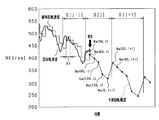
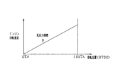
- FIG. 2 shows the transition of the engine rotational speed during the rotation descent period until the combustion of the engine 11 is stopped and the engine rotational speed becomes zero.
- the self-sustaining return area is an area of the engine rotational speed at which the engine 11 can be restarted by resuming fuel supply without cranking while the combustion of the engine 11 is stopped.
- the lower limit is about 600 rpm. It is set.
- the compression reaction force (compression reaction force) to the piston 13 may be larger than that after the engine 11 is stopped. Therefore, in the rotation drop period, it is considered that the output torque of the MG 30 is insufficient with respect to the compression reaction force, and the piston 13 may not be able to get over the compression top dead center (TDC). As a result, there is a concern that the startability may be reduced. That is, it is considered that there are cases where the engine 11 can not be reliably started. For example, when automatic restart is performed and the restart condition is satisfied when the engine rotational speed is approximately zero, since the rotational energy (inertial force, inertia) of the crankshaft 14 is reduced, the compression resistance is relatively reduced. The power is increased, and the occurrence of such inconvenience is a concern.
- the ECU 50 of the present embodiment has a function as the overpass determination unit 61 that executes the overpass determination based on the rotational state of the crankshaft 14 in the rotation drop period. Further, the ECU 50 has a function as a start control unit 62 which starts the driving of the MG 30 in a low reaction force period in which the reaction force applied to the piston 13 is equal to or less than a predetermined level.
- the overpass determination unit 61 executes the overpass determination based on the rotational state of the crankshaft 14 in the rotation drop period.
- the ECU 50 has a function as a start control unit 62 which starts the driving of the MG 30 in a low reaction force period in which the reaction force applied to the piston 13 is equal to or less than a predetermined level.
- the overtaking determination unit 61 will be described.
- the ECU 50 stores the history of the engine rotational speed in the storage unit (memory for storage) as the rotational state of the crankshaft 14 during the rotation drop period. Then, the ECU 50 as the overtaking determination unit 61 predicts the engine rotational speed based on the history, and executes the overcoming determination by using the prediction data. Therefore, the ECU 50 of the present embodiment has a function as a storage unit that stores the history of the engine rotational speed in the rotation decrease period, and a function as a stop prediction unit that predicts the engine rotational speed based on the history of the engine rotational speed. It will be.
- the method of predicting the engine rotational speed will be described.
- the ECU 50 takes one cycle of increase and decrease of the engine rotational speed according to the increase and decrease of the cylinder volume as a rotational pulsation period, and predicts the engine rotational speed of the subsequent rotational pulsation period based on the loss energy of the previous rotational pulsation period. An engine rotation speed during forward rotation of the engine is predicted.
- the ECU 50 assumes that the energy loss during positive rotation during the rotation descent period is constant if the rotational position of the crankshaft 14 determined by the piston position is the same. Then, based on this assumption, the ECU 50 takes one cycle (180.degree. CA in this embodiment) of increase and decrease of the engine rotational speed (instant rotational speed Ne) accompanying the increase and decrease of the cylinder volume as a rotational pulsation period before the current time.
- the engine rotation speed in the subsequent rotation pulsation period is predicted based on the engine rotation speed in the rotation pulsation period.
- the ECU 50 predicts the engine rotational speed after the current time on the assumption that the engine torque is generated in the same tendency during the forward and reverse rotational pulsation periods during the normal rotation of the engine.
- the instantaneous rotational speed Ne is an engine rotational speed calculated from the time required for the rotation of the crankshaft 14 at a predetermined rotational angle.
- a predicted value of the rotational position (crank angle) at which the next crank pulse signal is output that is, the instantaneous rotational speed Ne at the next calculation timing is calculated, and based on the predicted value
- a process of calculating a predicted value of the instantaneous rotational speed Ne at the calculation timing is repeated a plurality of times. This enables prediction of the engine rotational speed (identification of a predicted rotational trajectory) within the rotation fall period.
- FIG. 3 is a diagram for explaining a method of predicting the engine rotational speed.
- the current rotational pulsation period is S [j] and the previous rotational pulsation period is S [j ⁇ 1], the next rotational pulsation period is indicated as S [j + 1].
- the ECU 50 Every time a crank pulse signal is input from the crank angle sensor 51 (every 30 ° CA in the present embodiment), the ECU 50 starts the current pulse rise timing from the previous pulse in the rotation drop period after the engine automatic stop condition is established.
- the instantaneous rotational speed Ne (i) is calculated on the basis of the time width ⁇ t [sec] which is the time to the rise timing of the pulse, and this is stored each time.
- the engine torque Te ( ⁇ n ⁇ Calculate ⁇ n +1).
- the engine torque Te (j-1) (. Theta.n-.theta.n + 1) -J. ((. Omega. (J-1) (. Theta.n + 1)) 2-(. Omega. (J-1) (.
- J is the inertia of the engine 11 (crankshaft 14), and in this embodiment, it is calculated in advance based on design data of the engine 11 and the like and stored in the storage unit.
- Te (j-1) (30-60) and the current instantaneous rotation speed Ne (30, i) the engine rotation speed as the predicted value of the next pulse rising timing
- Ne (60, i) at the position 60 ° CA is calculated.
- the estimated arrival time t (j) (30-60) for reaching the rotational position of 30 ° CA to 60 ° CA is calculated.
- the engine torque Te (j-1) (60-90) from the rotation position 60 ° CA to 90 ° CA of the previous 180 ° CA section S [j-1], and the predicted value Ne of the engine rotation speed (60) , i) is used to calculate the predicted value Ne (90, i) of the rotational position of the rotational angle 90 ° CA after TDC in the current 180 ° CA section S [j], and from the rotational position 60 ° CA
- the predicted arrival time t (j) (60-90) to reach 90 ° CA is calculated. This process is repeated many times to predict the engine rotational speed (instant rotational speed Ne) in the rotational descent period of the engine 11, and, for example, linearly interpolate the predicted data to obtain the engine rotational speed in the rotational descent period. Predict the trajectory (predicted rotational trajectory).
- the predicted value of the instantaneous rotational speed Ne calculated based on this prediction method is indicated by a black circle in FIG. 3, and the predicted rotational trajectory is indicated by a broken line in the figure.
- This prediction calculation is executed every time the crank pulse signal is input (every 30 ° CA) using the time until the next crank pulse signal is input, and the prediction data (predicted rotational trajectory) is updated each time. Ru. At this time, in the period until the next crank pulse signal input, the trajectory until the rotation of the engine 11 stops is predicted.
- the engine rotation speed (instant rotation speed) may be converted into angular velocity to perform prediction calculation.
- the ECU 50 performs the overcoming determination to determine whether or not the piston 13 can get over the compression top dead center, based on the prediction data.
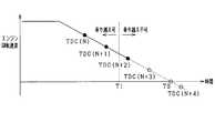
- a point T0 at which the engine rotational speed becomes zero is specified based on predicted data (predicted rotational trajectory) indicated by a broken line.
- the actual engine rotational speed is schematically shown by a solid line.
- the ECU 50 specifies a top dead center (TDC (N + 3) in FIG. 4) one before the time point T0 from the predicted data of the engine speed based on the time point T0 at which the engine speed is zero.
- the piston 13 can not go over the top dead center at time T0 or later (for example, TDC (N + 4) in FIG. 4) when the engine rotational speed becomes zero. Therefore, the ECU 50 denies the overtaking determination when the overcoming determination is performed at least in the period from time TDC (N + 3) to the time T0 when the engine rotational speed becomes zero.
- the ECU 50 specifies a top dead center (TDC (N + 2) in FIG. 4) two points before on the basis of the time point T0 at which the engine rotational speed is zero. Then, it is desirable that the ECU 50 negates the overtaking determination also when performing the overcoming determination from the TDC (N + 2) to the time T0 when the engine rotational speed becomes zero. That is, in the exhausting process, in view of the possibility that the piston 13 can not exceed the top dead center, the overtaking determination can be denied in the period from time T0 when the engine rotational speed becomes zero from TDC (N + 2). desirable.
- fuel injection may be performed before an intake stroke.
- the ECU 50 performs overcoming determination in a period from time T1 at which the engine rotational speed becomes zero from time T1 which is a predetermined time before TDC (N + 2) (that is, a start request occurs). ), Deny the surrender judgment. That is, the overtaking determination is performed in consideration of the time for fuel injection and the fact that the engine is a four-stroke engine. The ECU 50 denies the overtaking determination even after time T0 at which the engine rotational speed is zero.
- the ECU 50 as the start control unit 62 determines that the piston 13 can get over the compression top dead center in the rotation drop period, and starts the driving of the MG 30 as soon as possible when the restart condition is satisfied. That is, when the overcoming determination is affirmed, since the inertial force based on the rotational energy of the crankshaft 14 is larger than the compression reaction force, the compression reaction force is offset. As a result, even when the piston 13 is stopped, the output torque required to start the engine 11 does not increase. For this reason, the ECU 50 restarts the engine 11 promptly by starting the driving of the MG 30 as soon as possible when the overriding determination is affirmed.
- the ECU 50 as the start control unit 62 determines that the piston 13 can not get over the compression top dead center during the rotation descent period, and the reaction force applied to the piston 13 is predetermined when the restart condition is satisfied.
- the driving of the MG 30 is started in a low reaction force period which is as follows.
- the ECU 50 sets a waiting time from when the regeneration condition is satisfied to when the low reaction force period is reached. Then, the ECU 50 starts driving of the MG 30 at the timing when the waiting time has elapsed.
- the ECU 50 sets the waiting time according to the engine rotation speed when the restart condition is satisfied (when the start request is generated). That is, since it is assumed that the engine rotational speed falls with a predetermined periodicity, the period in which the in-cylinder pressure in the cylinder 12 decreases and the reaction force applied to the piston 13 becomes less than or equal to the predetermined is predicted from the engine rotational speed can do. Specifically, a period (low reaction force period) in which the engine rotational position is near 90 ° CA can be predicted from the engine rotational speed. Therefore, the waiting time is set according to the engine rotational speed. The higher the engine rotational speed is, the larger the compression reaction force is, so the waiting time is made longer. Therefore, the ECU 50 has a function as a setting unit that sets the waiting time until the low reaction force period is reached.
- the waiting time is measured, for example, by experiments and stored in the storage unit for each engine rotational speed.
- the waiting time according to the engine rotation speed may be determined based on the design data and stored in the storage unit.
- the ECU 50 may set the waiting time by predicting the low reaction force period based on the above-described prediction data. For example, the ECU 50 may set a waiting time by predicting a period (low reaction force period) in which the engine rotational position is near 90 ° CA using the periodicity of the above-described prediction data.
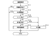
- the ECU 50 determines whether the restart condition is satisfied (whether or not the start request has been generated) (step S11). If the determination result is negative, the start control process is ended.
- step S11 determines whether the engine rotational speed is in the self-sustained return region (step S12). If the determination result is affirmative, the ECU 50 ends the start control process without driving the MG 30. That is, the engine 11 is restarted by restarting the fuel supply.
- step S12 determines whether the engine 11 has completely stopped (the rotation of the engine 11 has stopped) based on the engine rotation speed and the like (step S13). If the determination result is affirmative, the ECU 50 immediately starts driving the MG 30 (step S14), restarts the engine 11, and ends the start control process.
- step S16 the ECU 50 executes a special restart process (step S16).
- the special restart process is a process for starting (restarting) the engine 11 when the engine rotational speed is in the low speed region (period after the passage of the self-sustained return region until the engine 11 completely stops). is there. After the special restart process is executed, the start control process is ended.
- step S16 will be described based on FIG.
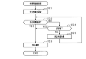
- the ECU 50 sets a waiting time from when the restart condition is satisfied to when the low reaction force period is reached (step S21). That is, the ECU 50 sets the waiting time according to the engine rotational speed when the restart condition is satisfied (when the start request is generated).
- the ECU 50 determines whether the waiting time has elapsed (step S22). If the determination result is affirmative, the ECU 50 starts driving of the MG 30 (step S23), and restarts the engine 11. Then, the special restart process is ended.
- step S24 the ECU 50 determines whether the crankshaft 14 is reversely rotating.
- the rotational direction of the crankshaft 14 can be determined by the transition of the rotational position acquired by the crank angle sensor 51 or the like.
- step S24 If the determination result of step S24 is affirmative (if the crankshaft 14 is reversely rotating), the ECU 50 immediately starts driving of the MG 30 (step S23), and restarts the engine 11. Then, the special restart process is ended.
- step S24 when the determination result of step S24 is negative (when the crankshaft 14 is positively rotating), the ECU 50 waits for a predetermined time (step S25), and then proceeds to the process of step S22.
- the ECU 50 performs the overrun determination to determine whether or not the piston 13 can get over the compression top dead center based on the rotation state of the crankshaft 14 in the rotation lowering period. Then, when it is determined that the piston 13 can not get over the compression top dead center, the ECU 50 starts driving of the MG 30 in a low reaction force period in which the reaction force applied to the piston 13 is less than a predetermined value. That is, when there is a possibility that the output torque of MG 30 is insufficient with respect to the reaction force applied to piston 13 in the rotation descent period, driving of MG 30 is started in the low reaction force period to reliably start engine 11 I did it. Thus, the engine 11 can be appropriately started while suppressing the output torque of the MG 30 during the rotation decrease period.
- the ECU 50 can not get over the compression top dead center in the rotational state of the crankshaft 14, and the output torque of the MG 30 is insufficient with respect to the reaction force applied to the piston 13. If it is determined that there is a possibility of becoming, the drive of the MG 30 is waited until the low reaction force period is reached. Thus, the engine 11 can be appropriately started while suppressing the output torque of the MG 30 during the rotation decrease period.
- the ECU 50 sets a waiting time until the low reaction force period starts, based on the engine rotational speed when the restart condition is satisfied (when the start request is generated). That is, even without using an in-cylinder pressure sensor or the like, the low reaction force period can be predicted (specified) from the engine rotational speed, and the configuration can be simplified.
- the ECU 50 determines whether or not the crankshaft 14 is rotating in the normal direction, and when it is determined that the crankshaft 14 is rotating in the reverse direction, the driving of the MG 30 is started as the low reaction force period. did. Thereby, the engine 11 can be started at a suitable timing while suppressing the output torque.
- the ECU 50 predicts the engine rotational speed based on the history of engine rotational speeds, and performs overcoming determination based on the predicted data. It is most difficult for the piston 13 to get over the compression top dead center in a period immediately before the rotation of the engine 11 is stopped. On the other hand, the timing at which the engine 11 stops can be predicted based on the history of engine rotational speeds. Therefore, the engine rotation speed is predicted, and based on the prediction, it is decided to perform the overcoming determination. In this way, it can be determined whether or not it is possible to get over appropriately.
- control system is not limited to the above embodiment, and may be implemented, for example, as follows.
- symbol is attached
- the low reaction force period can be identified based on the rotational position of the crankshaft 14. Further, the rotational energy (inertial force) of the crankshaft 14 differs according to the engine rotational speed, and when the rotational energy is taken into consideration, the low reaction force period in which the reaction force applied to the piston 13 is less than a predetermined value also differs. That is, since the compression reaction force is offset by the inertia force of the crankshaft 14, the low reaction force period needs to be different according to the engine rotation speed.
- the rotational position of the crankshaft 14 and the engine rotational speed are acquired, and whether or not it is a low reaction force period based on the acquired combination of the rotational position of the crankshaft 14 and the engine rotational speed Can be determined.
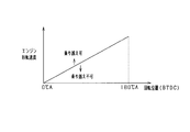
- a determination map for determining whether or not the low reaction force period is determined from the combination of the rotational position (BTDC) of the crankshaft 14 and the engine rotational speed is stored in the storage unit. did. Then, the ECU 50 determines whether or not the low reaction force period is in reference to the determination map.
- the determination map is set based on, for example, experiments or design data, and is stored in the storage unit.
- the determination map is, for example, as shown in FIG.
- the area above the solid line is an area determined to be a low reaction force period, and the area below the solid line is an area determined not to be a low reaction force period.
- the range of the rotational position serving as the low reaction force period becomes wider.
- the rotational position approaches the top dead center (0 ° CA) as the engine rotational speed decreases.
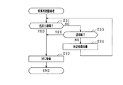
- the ECU 50 acquires the current engine rotational speed and rotational position, refers to the determination map based on the acquired engine rotational speed and rotational position, and determines whether or not it is in a low reaction force period (driving of the MG 30 is permitted It is determined whether or not it is a period (step S31). If the determination result is affirmative, the ECU 50 starts driving of the MG 30 (step S32), and restarts the engine 11. Then, the special restart process is ended.
- step S31 determines whether the crankshaft 14 is reversely rotating. If the determination result in step S33 is affirmative (if the crankshaft 14 is reversely rotating), the ECU 50 immediately starts driving the MG 30 (step S32), and restarts the engine 11. Then, the special restart process is ended.
- step S34 the ECU 50 waits for a predetermined time (step S34), and then proceeds to the process of step S31.
- the ECU 50 has a function as a period determination unit that determines whether or not it is a low reaction force period based on the acquired rotational position of the engine output shaft and the engine rotational speed.
- the low reaction force period can be identified based on the rotational position of the crankshaft 14. Further, the rotational energy of the crankshaft 14 differs according to the engine rotational speed, and when the rotational energy is taken into consideration, the low reaction force period in which the reaction force applied to the piston 13 is less than a predetermined value also differs. That is, since the compression reaction force is offset by the inertia force of the crankshaft 14, the low reaction force period also differs.
- the ECU 50 determines whether or not it is in the low reaction force period based on the rotational position of the crankshaft 14 and the engine rotational speed, and starts the driving of the MG 30 when it is determined that it is the low reaction force period. I decided. Thereby, the engine 11 can be appropriately started while suppressing the output torque.
- control system is not limited to the above embodiment, and may be implemented, for example, as follows.
- symbol is attached
- the ECU 50 when it is determined that the crankshaft 14 is reversely rotating, the ECU 50 reversely rotates the crankshaft 14 until the compression reaction force applied to the piston 13 becomes minimum, and then the MG 30 is driven. Have started.
- the MG 30 is driven by a driving method different from that of the first embodiment. Specifically, the ECU 50 drives the MG 30 so that the output torque is applied in the direction in which the crankshaft 14 reversely rotates from before the low reaction force period. Then, the ECU 50 drives the MG 30 so that the output torque is applied in the direction in which the crankshaft 14 rotates positively in the low reaction force period.
- the ECU 50 sets a waiting time from when the restart condition is satisfied to when the low reaction force period is reached (step S41). That is, the ECU 50 sets the waiting time according to the engine rotational speed when the restart condition is satisfied (when the start request is generated).
- the ECU 50 determines whether the waiting time has elapsed (step S42). If the determination result is affirmative, the ECU 50 drives the MG 30 so that the output torque is applied in the direction in which the crankshaft 14 rotates forward (step S43), and restarts the engine 11. Then, the special restart process is ended.
- step S44 determines whether the crankshaft 14 is reversely rotating. If the determination result in step S44 is negative (if the crankshaft 14 is rotating in the positive direction), the ECU 50 drives the MG 30 so that the output torque is applied in the direction in which the crankshaft 14 rotates in the reverse direction (step S45). Then, after waiting for a predetermined time (step S46), the ECU 50 proceeds to the process of step S42.
- step S44 when the determination result in step S44 is affirmative (when the crankshaft 14 is reversely rotating), the ECU 50 reversely rotates the crankshaft 14 until the compression reaction force applied to the piston 13 becomes minimum. It is determined whether or not (step S47). Specifically, the ECU 50 determines whether the rotational position is 90 ° CA.
- step S47 If the determination result in step S47 is affirmative, the ECU 50 drives the MG 30 so that the output torque is applied in the direction in which the crankshaft 14 rotates forward (step S43), and restarts the engine 11. Then, the special restart process is ended.
- step S47 when the determination result of step S47 is negative, the ECU 50 drives the MG 30 so that the output torque is applied in the direction in which the crankshaft 14 rotates in the reverse direction (step S48). Then, after waiting for a predetermined time (step S49), the ECU 50 proceeds to the process of step S47.
- the ECU 50 when it is determined that the crankshaft 14 is rotating in the positive direction, the ECU 50 causes the MG 30 to apply output torque in the direction in which the crankshaft 14 rotates in the reverse direction before the low reaction force period. Although it did not drive. That is, the process of step S45 may be omitted.
- step S48 may be omitted.
- the ECU 50 may drive the MG 30 so that the output torque is applied in the direction in which the crankshaft 14 rotates in the reverse direction before the low reaction force period regardless of the rotation direction of the crankshaft 14.
- processing may be performed to drive the MG 30 so that the output torque is applied in the direction in which the crankshaft 14 rotates in the reverse direction between step S41 and step S42.
- the ECU 50 drives the MG 30 so that the output torque is applied in the direction in which the crankshaft 14 rotates in the reverse direction before the low reaction force period when the crankshaft 14 rotates in the normal direction.
- the rotational energy of the crankshaft 14 can be reduced (the movement of the piston 13 can be braked).
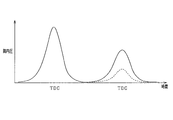
- FIG. Force can be reduced forcibly.
- the change in the in-cylinder pressure when the MG 30 is not driven is indicated by a solid line.
- the in-cylinder pressure when the MG 30 is driven is indicated by a broken line. Therefore, it is possible to start appropriately while suppressing the output torque.
- the ECU 50 drives the MG 30 so that the output torque is applied in the direction in which the crankshaft 14 rotates in the reverse direction when the crankshaft 14 rotates in the reverse direction. Thereby, the time until the compression reaction force becomes minimum can be shortened. That is, the timing of restarting can be made earlier.
- the ECU 50 may cause the field current to flow from before the low reaction force period.
- the ECU 50 may energize the field current after shifting to the special restart process.
- the responsiveness at the time of starting the driving of the MG 30 is improved. Thereby, the engine 11 can be started more quickly.
- the ECU 50 performs the overcoming determination based on the predicted data of the engine rotational speed, but the overcoming determination may be performed by any method.
- the overpass determination may be performed based on the engine rotational speed and the rotational position.
- the period determined to be overable can be identified based on the rotational position of the crankshaft 14.
- the rotational energy (inertial force) of the crankshaft 14 differs according to the engine rotational speed, and when the rotational energy is taken into consideration, the period determined to be transmissible is also different. That is, since the compression reaction force is offset by the inertia force of the crankshaft 14, it is necessary to make the period determined to be overable different according to the engine rotation speed.
- the overpass determination can be performed based on the combination of the rotational position of the crankshaft 14 and the engine rotational speed. Therefore, from the combination of the rotational position (BTDC) of the crankshaft 14 and the engine rotational speed, the overpass determination map for determining whether or not overcoming is possible is stored in the storage unit, and the ECU 50 performs the overpass determination map The overtaking determination may be performed with reference.
- the overpass determination map is set, for example, by experiments.
- the overtaking determination map is, for example, as shown in FIG.
- the area above the solid line is an area determined to be overable, and the area below the solid line is an area determined to be inaccessible.
- the range of rotational positions determined to be overreachable becomes wider.
- the rotational position determined to be overreachable approaches the top dead center (0 ° CA).
- the SOC of the battery 35 is used as the state of the remaining battery capacity (remaining battery capacity) of the battery 35.
- the present invention is not limited to this.
- a voltage between terminals of the battery 35 may be used.
- the ECU 50 may have a function as a temperature information acquisition unit that acquires temperature information of at least one of the engine 11 and the MG 30. Then, the ECU 50 may perform the correction of the low reaction force period based on the acquired temperature information. That is, the compression reaction force, the output torque of the MG 30, and the like fluctuate depending on the temperature state of the engine 11 and the MG 30. Therefore, the ECU 50 may change the waiting time until the low reaction force period in consideration of these. As a result, even if the output torque is suppressed, restart can be reliably performed. Also, similarly, the ECU 50 may perform correction of the overcoming determination based on the acquired temperature information.
- the ECU 50 may obtain the remaining battery charge (remaining battery charge) of the battery 35 and correct the low reaction force period based on the remaining battery charge. That is, the output torque of the outputtable motor fluctuates due to the remaining battery capacity. Therefore, the ECU 50 may change, for example, the waiting time until the low reaction force period based on the remaining battery capacity. As a result, even if the output torque is suppressed, restart can be reliably performed. Similarly, the ECU 50 may correct overcoming determination based on the acquired remaining battery charge.
- the above control in the rotation descent period until the engine rotation speed becomes zero may be implemented not only in the case of the automatic stop of the engine 11 but also in the case of the stop by the driver's ignition switch operation. In addition, it may be a stop in the vehicle 10 which does not have the idling stop function.
- the in-cylinder pressure sensor for detecting the in-cylinder pressure in the cylinder 12 is provided, the ECU 50 acquires the in-cylinder pressure, and specifies the low reaction force period based on the in-cylinder pressure or based on the engine rotation speed and the in-cylinder pressure. You may Further, the ECU 50 may carry out the overriding determination based on the in-cylinder pressure or based on the engine rotational speed and the in-cylinder pressure.
- the ECU 50 as the overpass determination unit 61 may perform overpass determination based on the rotation state of the crankshaft 14 and the outputtable torque of the MG 30. For example, even if the rotation state of the crankshaft 14 is the same, when the outputtable torque of the MG 30 is large, the overtaking determination may be easily determined as an affirmative determination as compared to the case where the output torque is small.
- the outputtable torque of the MG 30 may be calculated based on the remaining battery capacity, the temperature of the MG 30, and the like.
Abstract
エンジン始動制御装置(50)は、回転降下期間において、始動要求が生じた場合、エンジン出力軸の回転状態に基づいて、エンジンの気筒(12)内のピストン(13)が圧縮上死点を乗り越えられるか否かを判定する乗り越え判定を実行する乗り越え判定部(61)を備える。また、ピストンが圧縮上死点を乗り越えられないと判定された場合、気筒内の筒内圧によりピストンに加えられる反力が所定以下となる低反力期間で電動機(30)の駆動を開始させ、エンジンを始動させる始動制御部(62)と、を備える。
Description
本出願は、2017年7月31日に出願された日本出願番号2017-147856号に基づくもので、ここにその記載内容を援用する。
本開示は、エンジン始動制御装置に関するものである。
従来、例えばアクセル操作やブレーキ操作などといった停車又は発進のための動作等を検知してエンジンの自動停止及び自動再始動を行う、所謂アイドリングストップ機能を備えるエンジン制御システムが知られている。このアイドリングストップ制御によりエンジンの燃費低減等の効果を図っている。
また従来、モータジェネレータ(回転電機)を駆動してエンジンの再始動を行うエンジン始動方法が知られている(例えば、特許文献1)。
ところで、エンジンを自動停止させる際のエンジン回転速度の降下中に再始動要求が行われる可能性がある。この場合、気筒内への吸気が繰り返し行われているため、エンジンの停止後と比較してピストンに加えられる圧縮反力(コンプレッション反力)が大きくなる。そのため、エンジン回転速度の降下中においては、圧縮反力に対してモータジェネレータの出力トルクが不十分となり、ピストンが圧縮上死点を乗り越えられない場合があると考えられる。その結果、始動性が低下するという不都合が懸念される。例えば、エンジン自動停止に際し、エンジン回転速度が略ゼロ付近において再始動要求が行われる場合には、エンジン出力軸の回転エネルギ(慣性力、イナーシャ)が低下していることから、前記不都合の発生が懸念される。
このようにピストンへの反力が大きくなることを想定して、エンジンを再始動させるには、モータジェネレータによる出力トルクを大きくすることが必要となる。しかしながら、モータジェネレータによる出力トルクを大きくすることは、いろいろな制約があるため困難であった。
例えば、搭載スペースの都合上、モータジェネレータの体格を大きくして、出力トルクを大きくすることが困難であった。また、モータジェネレータの最大回転数には上限があるため、減速比を大きくして出力トルクを大きくすることも困難であった。
本開示は、上記課題を解決するためになされたものであり、エンジンの燃焼停止後、エンジンの回転が停止するまでの回転降下期間において、電動機による出力トルクを抑えつつ、エンジンの始動を適切に行うことができるエンジン始動制御装置を提供することを主たる目的とする。
上記課題を解決するため、第1の開示は、エンジン出力軸に駆動連結され、力行駆動の機能を有する電動機を備え、始動要求に応じて前記電動機によりエンジンを始動させるエンジン始動制御装置において、前記エンジンの燃焼が停止された後、エンジン回転速度がゼロまで降下する際の回転降下期間において、前記始動要求が生じた場合、前記エンジン出力軸の回転状態に基づいて、前記エンジンの気筒内のピストンが圧縮上死点を乗り越えられるか否かを判定する乗り越え判定を実行する乗り越え判定部と、前記ピストンが圧縮上死点を乗り越えられないと判定された場合、前記気筒内の筒内圧により前記ピストンに加えられる反力が所定以下となる低反力期間で前記電動機の駆動を開始させ、前記エンジンを始動させる始動制御部と、を備えたことを要旨とする。
回転降下期間において、始動要求が生じた場合、エンジン出力軸の回転状態に基づいて、エンジンの気筒内のピストンが圧縮上死点を乗り越えられるか否かを判定する乗り越え判定を実行する。そして、ピストンが圧縮上死点を乗り越えられないと判定された場合、ピストンに加えられる反力が所定以下となる低反力期間で前記電動機の駆動を開始させる。すなわち、回転降下期間において、ピストンに加えられる反力に対して電動機の出力トルクが不十分となる可能性がある場合、低反力期間において電動機の駆動を開始させ、確実にエンジンを始動させることした。これにより、回転降下期間において、電動機による出力トルクを抑えつつ、エンジンの始動を適切に行うことができる。
第2の開示は、前記ピストンが圧縮上死点を乗り越えられないと判定された場合に、前記始動要求が生じた時点から前記低反力期間になるまでの待ち時間を設定する設定部を備え、前記始動制御部は、前記待ち時間が経過したタイミングで前記電動機の駆動を開始させることを要旨とする。
始動要求が生じた時点において、エンジン出力軸の回転状態では、ピストンが圧縮上死点を乗り越えられず、圧縮反力に対して電動機の出力トルクが不十分となる可能性があると判定された場合、低反力期間となるまで電動機の駆動を待つこととした。これにより、回転降下期間において、電動機による出力トルクを抑えつつ、エンジンの始動を適切に行うことができる。
第3の開示は、前記設定部は、前記始動要求が生じた時点のエンジン回転速度に基づいて、前記待ち時間を設定することを要旨とする。
筒内圧センサなどを使用しなくても、始動要求が生じた時のエンジン回転速度から圧縮反力が所定以下となる低反力期間を予測することができる。これにより、構成を簡単にすることができる。
第4の開示は、前記ピストンが圧縮上死点を乗り越えられないと判定された後、前記エンジン出力軸の回転位置及びエンジン回転速度を取得し、取得した前記エンジン出力軸の回転位置及びエンジン回転速度に基づき、前記低反力期間であるか否かを判定する期間判定部を備えることを要旨とする。
エンジン出力軸の回転位置に応じて、圧縮反力は異なるため、低反力期間は、エンジン出力軸の回転位置に基づき特定可能である。また、エンジン回転速度に応じてエンジン出力軸の回転エネルギは異なり、その回転エネルギを考慮した場合、ピストンに加えられる反力が所定以下となる低反力期間も異なる。つまり、圧縮反力が、エンジン出力軸の慣性力により相殺されるため、低反力期間も異なることとなる。
そこで、エンジン出力軸の回転位置及びエンジン回転速度に基づき、低反力期間であるか否かを判定する期間判定部を備え、始動制御部は、期間判定部により低反力期間であると判定された場合に、電動機の駆動を開始させることとした。これにより、出力トルクを抑えつつ、適切にエンジンを始動させることができる。
第5の開示は、前記始動制御部は、前記低反力期間よりも前から前記エンジン出力軸が逆回転する方向に出力トルクが加わるように前記電動機を駆動させ、前記低反力期間において前記エンジン出力軸が正回転する方向に出力トルクが加わるように前記電動機を駆動させることを要旨とする。
エンジン出力軸が逆回転する方向に出力トルクが加わるように電動機を駆動させることにより、エンジン出力軸の回転エネルギを下げることができ、圧縮反力を強制的に低減させることができる。これにより、出力トルクを抑えつつ、適切に始動させることができる。
第6の開示は、前記エンジン出力軸が逆回転しているか否かを判定する回転判定部を備え、前記始動制御部は、前記エンジン出力軸が逆回転している判定された場合、前記低反力期間であるとして、前記電動機の駆動を開始させることを要旨とする。
エンジン出力軸が逆回転している場合、気筒内の筒内圧は十分に低下しているため、ピストンに加えられる反力が所定以下となる低反力期間として特定可能である。そこで、エンジン出力軸が逆回転しているか否かを判定する回転判定部を備え、始動制御部は、エンジン出力軸が逆回転している判定された場合、低反力期間であるとして、前記電動機の駆動を開始させることとした。これにより、出力トルクを抑えつつ、エンジンを好適なタイミングで始動させることができる。
第7の開示は、前記エンジン出力軸が逆回転しているか否かを判定する回転判定部を備え、前記始動制御部は、前記エンジン出力軸が逆回転していると判定された場合、前記ピストンに加えられる圧縮反力が最小となるまで前記エンジン出力軸を逆回転させてから、前記電動機の駆動を開始させることを要旨とする。
逆回転していると判定され、低反力期間であると判定された場合であっても、圧縮反力が最小となるまで電動機の駆動を開始させることを待機する。これにより、より確実にエンジンを始動させることができる。
第8の開示は、前記始動制御部は、前記エンジン出力軸が逆回転していると判定された場合、前記ピストンに加えられる圧縮反力が最小となる前から前記エンジン出力軸が逆回転する方向に出力トルクが加わるように前記電動機を駆動させ、前記圧縮反力が最小となった場合に前記エンジン出力軸が正回転する方向に出力トルクが加わるように前記電動機を駆動させることを要旨とする。
エンジン出力軸が逆回転している場合、エンジン出力軸が逆回転する方向に出力トルクが加わるように電動機を駆動させることにより、圧縮反力が最小となるまでの時間を短くすることができる。すなわち、再始動させるタイミングを早くすることができる。
第9の開示は、前記始動制御部は、前記低反力期間よりも前から界磁電流を通電させることを要旨とする。
これにより、電動機を駆動させる際の応答性を向上させることができる。
第10の開示は、前記回転降下期間におけるエンジン回転速度の履歴を記憶する記憶部と、前記記憶部に記憶されたエンジン回転速度の履歴に基づき、前記エンジン回転速度を予測する停止予測部を備え、前記乗り越え判定部は、前記停止予測部による予測に基づき、前記乗り越え判定を行うことを要旨とする。
エンジンの回転が停止するよりも直前の期間において、最もピストンが圧縮上死点を乗り越えにくくなる。一方、エンジンの回転が停止するタイミングは、エンジン回転速度の履歴に基づき予測可能である。そこで、エンジン回転速度を予測し、その予測に基づき、乗り越え判定を行うこととした。これにより、適切に乗り越えられるか否かを判定することができる。
第11の開示は、前記乗り越え判定部は、前記エンジン出力軸の回転状態と前記電動機の出力可能トルクに基づき、前記乗り越え判定を実行することを要旨とする。
これにより、より正確に乗り越え判定を実行することができる。
第12の開示は、前記エンジン及び前記電動機のうち少なくともいずれかの温度情報を取得する温度情報取得部を備え、前記温度情報取得部により取得された温度情報に基づき、前記低反力期間の補正が行われることを要旨とする。
温度により、圧縮反力や出力可能な電動機の出力トルク等が変動する。そこで温度情報に基づき、低反力期間を補正することとした。これにより、出力トルクを抑えても、確実に再始動させることができる。
第13の開示は、前記電動機へ電力を供給するバッテリの電池残量を取得する電池残量取得部を備え、前記電池残量取得部により取得された電池残量に基づき、前記低反力期間の補正が行われることを要旨とする。
電池残量により、出力可能な電動機の出力トルクが変動する。そこで電池残量に基づき、低反力期間を補正することとした。これにより、出力トルクを抑えても、確実に再始動させることができる。
本開示についての上記目的およびその他の目的、特徴や利点は、添付の図面を参照しながら下記の詳細な記述により、より明確になる。その図面は、
図1は、エンジン制御システムの概略構成図であり、
図2は、回転降下期間でのエンジン回転速度の推移チャートであり、
図3は、エンジン回転速度の予測を説明するための図であり、
図4は、乗り越え判定が否定される期間を示す図であり、
図5は、始動制御処理を示すフローチャートであり、
図6は、特殊再始動処理を示すフローチャートであり、
図7は、判定用マップを示す図であり、
図8は、第2実施形態の特殊再始動処理を示すフローチャートであり、
図9は、第3実施形態の特殊再始動処理を示すフローチャートであり、
図10は、筒内圧の変化を示す図であり、
図11は、乗り越え判定用マップを示す図である。
(第1実施形態)
以下、本開示を具体化した実施形態を図面に基づいて説明する。本実施形態は、車両に搭載されたエンジンの制御システムを具体化している。当該制御システムでは、電子制御ユニット(以下、ECUという)を中枢としてエンジンの運転状態等を制御する。本システムの全体概略図を図1に示す。
以下、本開示を具体化した実施形態を図面に基づいて説明する。本実施形態は、車両に搭載されたエンジンの制御システムを具体化している。当該制御システムでは、電子制御ユニット(以下、ECUという)を中枢としてエンジンの運転状態等を制御する。本システムの全体概略図を図1に示す。
図1に示す車両10において、エンジン11は、ガソリン等の燃料の燃焼によって駆動され、吸気、圧縮、膨張及び排気の各行程を繰り返し実施する4サイクルエンジン(4ストロークエンジン)である。エンジン11は、4つの気筒(シリンダ)12を有し、各気筒12にはピストン13がそれぞれ収容されている。また、エンジン11は、燃料噴射弁(図示せず)や点火装置(図示せず)等を適宜備えている。なお、本実施形態では、4気筒のエンジン11を示しているが、エンジン11の気筒数はいくつであってもよい。また、エンジン11はガソリンエンジンに限定されず、ディーゼルエンジンであってもよい。
気筒12には、吸気部20から空気が供給される。吸気部20は、吸気マニホールド21を有し、吸気マニホールド21の上流には、吸入空気量を調整するスロットルバルブ22が設けられている。
エンジン11には、MG(モータジェネレータ)30が一体に設けられている。MG30は、電動機及び発電機として駆動する回転電機である。エンジン11のクランク軸(エンジン出力軸)14は、クランクプーリ15に機械的に接続され、MG30の回転軸31は、MGプーリ32に機械的に接続されている。そして、クランクプーリ15とMGプーリ32とは、ベルト33により駆動連結されている。エンジン始動時には、MG30の回転によりエンジン11に初期回転(クランキング回転)が付与される。なお、別途スタータモータを設け、スタータモータの回転によりエンジン11に初期回転を付与可能とする構成としてもよい。
また、MG30は、電力変換回路であるインバータ34を介してバッテリ35に接続されている。MG30が電動機として駆動する場合には、ECU50の指令により、電力がバッテリ35からインバータ34を介してMG30に供給される。その結果、MG30が駆動(力行駆動)する。インバータ34には、ECU50の指令を受けてインバータ34の電力変換回路を制御する別のECUが設けられていてもよい。一方、MG30が発電機として機能する場合には、MG30で発電した電力が、インバータ34で交流から直流に変換された後、バッテリ35に充電される。なお、バッテリ35には、ランプ類やオーディオ装置等の電気負荷36が接続されている。
ECU50は、周知のCPU、ROM、RAM等よりなるマイクロコンピュータ等を備えてなる電子制御装置であり、本システムに設けられている各種センサの検出結果に基づいて、スロットルバルブ22の開度制御や、燃料噴射弁による燃料噴射の制御など各種エンジン制御を実施する。
センサ類について詳しくは、ECU50には、クランク軸14の回転位置(回転角度位置、クランク角)及びエンジン回転速度を検出するクランク角センサ51が接続されている。また、ECU50には、アクセル操作量(アクセル開度)を検出するアクセルセンサ52が接続されている。また、ECU50には、車速を検出する車速センサ53や、ブレーキペダルの操作量を検出するブレーキセンサ54が接続されている。また、ECU50には、バッテリ35のバッテリ状態を検出するバッテリセンサ56が接続されている。これら各センサからの信号がECU50に逐次入力されるようになっている。
クランク角センサ51は、例えば、所定のクランク角ごとに(例えば、30°CA周期で)、矩形状の検出信号(クランクパルス信号)を出力する電磁ピックアップ式の回転位置検出装置である。クランク軸14が所定のクランク角を回転する度に要した時間からエンジン回転速度が算出される。また、クランク角センサ51の検出結果によれば、所定の基準位置(例えば圧縮上死点)に対するクランク軸14の回転位置(回転角度位置、クランク角)が算出される他、エンジン11の行程判別が実施される。
バッテリセンサ56は、バッテリ35の端子間電圧や充放電電流等を検出する。これら検出値に基づいて、バッテリ35のバッテリ残容量(SOC)がECU50により算出される。したがって、ECU50は、電池残量取得部として機能する。
また、ECU50は、エンジン11のアイドリングストップ制御を行う。アイドリングストップ制御は、概略として、所定の自動停止条件が成立するとエンジン11の燃焼が停止されるとともに、その後、所定の再始動条件が成立するとエンジン11が再始動される。この場合、自動停止条件には、例えば、自車両の車速がエンジン自動停止速度域(例えば、車速≦10km/h)にあり、かつアクセル操作が解除されたこと又はブレーキ操作が行われたことが含まれる。また、再始動条件としては、例えば、アクセル操作が開始されたことや、ブレーキ操作が解除されたことが含まれる。なお、エンジン制御機能とアイドリングストップ機能とを別々のECUにて実施する構成にすることも可能である。したがって、ECU50は、エンジン始動制御装置である。
ここで、車両10において、エンジン11の自動停止条件が成立した場合におけるエンジン回転速度の推移について説明する。図2には、エンジン11の燃焼が停止され、エンジン回転速度がゼロとなるまでの回転降下期間におけるエンジン回転速度の推移を示す。アイドル状態からエンジン11の自動停止条件が成立すると、エンジン11の燃焼は停止される。その後、エンジン回転速度は徐々に低下し、自立復帰領域を通過する。ここで、自立復帰領域は、エンジン11の燃焼停止中にクランキングをすることなく燃料供給の再開により、エンジン11の再始動が可能なエンジン回転速度の領域であり、例えば、下限が600rpm程度に設定される。
そして、自立復帰領域を通過して、さらにエンジン回転速度が徐々に低下すると、低速度領域を通過し、エンジン回転速度がゼロとなる(エンジン11の回転が停止する)。なお、エンジン11の回転が停止する間際において、エンジン11の揺り戻し(逆回転)が生じる場合がある。この揺り戻しは、エンジン11が停止する際に、気筒12内の筒内圧に基づき、ピストン13に加えられる圧縮反力(コンプレッション反力)によって、ピストン13が下死点方向へ押し戻されることで発生する。
ところで、本システムでは、回転降下期間内に再始動条件が成立した場合(始動要求が生じた場合)、エンジン11の回転が完全に停止するのを待たずに、できるだけ早いタイミングでエンジン11を始動(再始動)させることとしている。
しかしながら回転降下期間では、気筒12内への吸気が繰り返し行われるため、エンジン11の停止後と比較して、ピストン13への圧縮反力(コンプレッション反力)が大きくなる可能性がある。そのため、回転降下期間においては、圧縮反力に対してMG30の出力トルクが不十分となり、ピストン13が圧縮上死点(TDC)を乗り越えられない場合があると考えられる。その結果、始動性が低下するという不都合が懸念される。つまり、確実にエンジン11を始動させることができない場合があると考えられる。例えば、エンジン自動停止に際し、エンジン回転速度が略ゼロ付近において再始動条件が成立した場合には、クランク軸14の回転エネルギ(慣性力、イナーシャ)が低下していることから、相対的に圧縮反力が大きくなり、このような不都合の発生が懸念される。
このようにピストン13に加えられる反力が大きくなることを想定して、エンジン11を再始動させるには、MG30による出力トルクを大きくすることが必要となる。しかしながら、MG30による出力トルクを大きくすることは、いろいろな制約があるため困難であった。
例えば、搭載スペースの都合上、MG30の体格を大きくして、出力トルクを大きくすることが困難であった。また、MG30の最大回転数には上限がある(MG30の回転数を大きくし過ぎると故障する可能性がある)ため、減速比を大きくして出力トルクを大きくすることも困難であった。
そこで、本実施形態では、エンジン回転速度が低速度領域である場合において、始動制御について工夫を施すことにより、MG30の出力トルクを抑えつつ、適切なエンジン11の再始動を可能とした。
具体的には、ECU50は、回転降下期間において、再始動条件が成立した場合、クランク軸14の回転状態に基づいて、ピストン13が圧縮上死点を乗り越えられるか否かを判定する乗り越え判定を実行することとした。そして、ECU50は、ピストン13が圧縮上死点を乗り越えられないと判定された場合、ピストン13に加えられる反力が所定以下となる低反力期間でMG30の駆動を開始させ、エンジン11を始動させることとした。
このため、本実施形態のECU50は、回転降下期間において、クランク軸14の回転状態に基づいて、乗り越え判定を実行する乗り越え判定部61としての機能を備える。また、ECU50は、ピストン13に加えられる反力が所定以下となる低反力期間でMG30の駆動を開始させ、エンジン11を始動させる始動制御部62としての機能を備える。以下、これらの機能について詳しく説明する。
まず、乗り越え判定部61について説明する。本実施形態において、ECU50は、回転降下期間において、クランク軸14の回転状態としてエンジン回転速度の履歴を記憶部(記憶用メモリ)に記憶する。そして、乗り越え判定部61としてのECU50は、当該履歴に基づき、エンジン回転速度を予測し、その予測データを用いることにより、乗り越え判定を実行している。したがって、本実施形態のECU50は、回転降下期間におけるエンジン回転速度の履歴を記憶する記憶部としての機能と、エンジン回転速度の履歴に基づき、エンジン回転速度を予測する停止予測部としての機能を備えていることとなる。
エンジン回転速度の予測方法について説明する。ECU50は、シリンダ容積の増減変化に伴うエンジン回転速度の増減1周期分を回転脈動期間とし、前の回転脈動期間のロスエネルギに基づいてその後の回転脈動期間のエンジン回転速度を予測することにより、エンジン正回転中のエンジン回転速度を予測する。
より詳細には、ECU50は、回転降下期間において正回転中のロスエネルギは、ピストン位置で決まるクランク軸14の回転位置が同じであれば一定であると仮定する。そして、ECU50は、この仮定に基づき、シリンダ容積の増減変化に伴うエンジン回転速度(瞬時回転速度Ne)の増減1周期分(本実施形態では180℃A)を回転脈動期間として、現時点よりも前の回転脈動期間のエンジン回転速度に基づいて、その後の回転脈動期間のエンジン回転速度を予測するものである。
つまり、ECU50は、エンジン正回転中では、前後する回転脈動期間でエンジントルクが同様の傾向で生じると仮定して、現時点よりも後のエンジン回転速度を予測する。なお、瞬時回転速度Neは、クランク軸14の所定回転角度の回転に要した時間から算出されるエンジン回転速度である。この予測方法では、次のクランクパルス信号が出力される回転位置(クランク角)、すなわち次の演算タイミングの瞬時回転速度Neの予測値を算出するとともに、その予測値に基づいて、更にその次の演算タイミングの瞬時回転速度Neの予測値を算出するといった処理を複数回繰り返す。これにより、回転降下期間内でのエンジン回転速度の予測(予測回転軌道の特定)が可能となる。
図3は、エンジン回転速度の予測方法を説明するための図である。なお、図3では、各気筒の上死点(TDC)から次のTDCまでの180℃A区間(回転脈動期間)のうち、今回の回転脈動期間をS[j]、前回の回転脈動期間をS[j-1]、次回の回転脈動期間をS[j+1]と示している。
ECU50は、エンジン自動停止条件の成立後の回転降下期間において、クランク角センサ51からクランクパルス信号が入力される毎に(本実施形態では30°CA毎に)、前回のパルスの立ち上がりタイミングから今回のパルスの立ち上がりタイミングまでの時間である時間幅Δt[sec]に基づいて瞬時回転速度Ne(i)を算出し、これを都度記憶する。
また、上死点(TDC)から所定回転角度θ(クランク分解能)ごとの瞬時回転速度Ne(θ,i-1)の変化に基づいて、回転脈動期間における回転位置間のエンジントルクTe(θn-θn+1)を算出する。例えば前回の回転脈動期間(前回の180℃A区間)S[j-1]における回転位置間のエンジントルクTe(j-1)(θn-θn+1)は、下記式(1)により表される。
Te(j-1)(θn-θn+1)=-J・((ω(j-1)(θn+1))2 -(ω(j-1)(θn))2)/2…(1)
ω(θn)[rad/sec]=Ne(θn)×360/60
なお、式(1)中、Jはエンジン11(クランク軸14)のイナーシャであり、本実施形態では予めエンジン11の設計データ等に基づいて算出して記憶部に記憶されている。
Te(j-1)(θn-θn+1)=-J・((ω(j-1)(θn+1))2 -(ω(j-1)(θn))2)/2…(1)
ω(θn)[rad/sec]=Ne(θn)×360/60
なお、式(1)中、Jはエンジン11(クランク軸14)のイナーシャであり、本実施形態では予めエンジン11の設計データ等に基づいて算出して記憶部に記憶されている。
図3において、現在の回転位置がTDC後30℃Aであり、それ以降のエンジン回転速度を予測する場合、まず、クランクパルス信号に基づいて、現時点の瞬時回転速度Ne(30,i)を算出する。また、その算出した瞬時回転速度Ne(30,i)と、直前の回転位置の瞬時回転速度Ne(0,i)とを用いて、上記式(1)によりエンジントルクTe(0-30,i)を算出し、これを記憶する。
次いで、前回の180℃A区間S[j-1]において、上死点(TDC)を基準とする回転位置が予測値と同じになる回転位置と、その前回の回転位置との間のエンジントルク、ここではエンジントルクTe(j-1)(30-60)と、現在の瞬時回転速度Ne(30,i)とを用いて、次のパルスの立ち上がりタイミングのエンジン回転速度の予測値として、回転位置60℃Aの予測値Ne(60,i)を演算する。併せて、回転位置30℃Aから60℃Aに到達するまでの予測到達時間t(j)(30-60)を演算する。
さらに、前回の180℃A区間S[j-1]の回転位置60℃Aから90℃AまでのエンジントルクTe(j-1)(60-90)と、エンジン回転速度の予測値Ne(60,i)とを用いて、今回の180℃A区間S[j]においてTDC後の回転角度90℃Aの回転位置の予測値Ne(90,i)を演算するとともに、回転位置60℃Aから90℃Aに到達するまでの予測到達時間t(j)(60-90)を演算する。この処理を何回も繰り返すことで、エンジン11の回転降下期間におけるエンジン回転速度(瞬時回転速度Ne)を予測するとともに、その予測データを例えば線形補間することにより、回転降下期間におけるエンジン回転速度の軌道(予測回転軌道)を予測する。なお、この予測方法に基づき算出した瞬時回転速度Neの予測値が図3中の黒丸で示すものであり、予測回転軌道が図中の破線で示すものである。
この予測演算は、クランクパルス信号の入力毎(30℃A毎)に、次のクランクパルス信号が入力されるまでの時間を利用して実行され、その都度予測データ(予測回転軌道)が更新される。このとき、次のクランクパルス信号入力までの期間では、エンジン11の回転が停止するまでの軌道を予測する。なお、エンジン回転速度(瞬時回転速度)を角速度に換算して予測演算を行うようにしてもよい。
そして、ECU50は、この予測データに基づき、ピストン13が圧縮上死点を乗り越えられるか否かを判定する乗り越え判定を実行する。
具体的には、図4に示すように、破線で示す予測データ(予測回転軌道)に基づき、エンジン回転速度がゼロとなる時点T0を特定する。なお、図4では、実際のエンジン回転速度を実線により模式的に示す。そして、ECU50は、エンジン回転速度の予測データから、エンジン回転速度が0となる時点T0を基準として、時点T0よりも1つ前の上死点(図4ではTDC(N+3))を特定する。エンジン回転速度が0となる時点T0以降(例えば、図4におけるTDC(N+4))において、ピストン13は上死点を乗り越えられない。このため、ECU50は、少なくとも当該TDC(N+3)からエンジン回転速度がゼロとなる時点T0の期間において、乗り越え判定を実施する場合、乗り越え判定を否定する。
また、本実施形態では、4ストローク(吸気、圧縮、膨張及び排気の各行程)を1つのサイクルとしている。つまり、エンジン11を始動させる場合、ピストン13は、2回上死点を乗り越える必要がある。したがって、ECU50は、エンジン回転速度がゼロとなる時点T0を基準として2つ前の上死点(図4ではTDC(N+2))を特定する。そして、ECU50は、当該TDC(N+2)から、エンジン回転速度がゼロとなる時点T0の期間において、乗り越え判定を実施する場合も、乗り越え判定を否定することが望ましい。つまり、排気する行程において、ピストン13が上死点を超えられない可能性を考慮して当該TDC(N+2)から、エンジン回転速度がゼロとなる時点T0の期間において、乗り越え判定を否定することが望ましい。
また、エンジン11を始動させる際、吸気行程の前に燃料噴射が行われる場合がある。この燃料噴射に係る時間を考慮して、TDC(N+2)又はTDC(N+3)よりも所定時間前から乗り越え判定を否定することが望ましい。
以上により、本実施形態のECU50は、TDC(N+2)よりも所定時間前の時点T1から、エンジン回転速度がゼロとなる時点T0の期間において、乗り越え判定を実施する場合(つまり、始動要求が生じた場合)、乗り越え判定を否定する。すなわち、燃料噴射に係る時間や4ストロークエンジンであることを考慮して乗り越え判定を実施している。なお、ECU50は、エンジン回転速度がゼロとなる時点T0以降においても、乗り越え判定を否定する。
次に、始動制御部62についての説明をする。始動制御部62としてのECU50は、回転降下期間において、ピストン13が圧縮上死点を乗り越えられると判定され、且つ、再始動条件が成立した場合、できるだけ早くMG30の駆動を開始させる。すなわち、乗り越え判定が肯定された場合、クランク軸14の回転エネルギに基づく慣性力が、圧縮反力よりも大きいため、圧縮反力が相殺される。その結果、ピストン13の停止時と比較しても、エンジン11の始動に要する出力トルクが大きくなるわけではない。このため、ECU50は、乗り越え判定が肯定された場合、できるだけ早くMG30の駆動を開始させることにより、エンジン11を迅速に再始動させている。
一方、始動制御部62としてのECU50は、回転降下期間において、ピストン13が圧縮上死点を乗り越えられないと判定され、且つ、再始動条件が成立した場合、ピストン13に加えられる反力が所定以下となる低反力期間でMG30の駆動を開始させる。
ここで、低反力期間でMG30の駆動を開始させる方法について説明する。
ECU50は、ピストン13が圧縮上死点を乗り越えられないと判定された場合、再生同条件の成立時から低反力期間になるまでの待ち時間を設定する。そして、ECU50は、待ち時間が経過したタイミングでMG30の駆動を開始させる。
より詳しく説明すると、ECU50は、再始動条件が成立した時(始動要求が生じた時)のエンジン回転速度に応じて待ち時間を設定する。すなわち、エンジン回転速度は、所定の周期性を持って降下すると仮定されるため、気筒12内の筒内圧が低下し、ピストン13に加えられる反力が所定以下となる期間をエンジン回転速度から予測することができる。具体的には、エンジン回転速度からエンジン回転位置が90℃A付近となる期間(低反力期間)を予測することができる。このため、エンジン回転速度に応じて待ち時間を設定することとしている。なお、エンジン回転速度が高ければ高いほど、圧縮反力が大きくなるため、待ち時間を長くしている。したがって、ECU50は、低反力期間になるまでの待ち時間を設定する設定部としての機能を備える。
この待ち時間は、例えば、実験等により測定されてエンジン回転速度ごとに記憶部に記憶されている。なお、設計データに基づき、エンジン回転速度に応じた待ち時間を決定し、記憶部に記憶しておいてもよい。また、ECU50は、前述した予測データに基づき、低反力期間を予測し、待ち時間を設定してもよい。例えば、ECU50は、前述した予測データの周期性を利用して、エンジン回転位置が90℃A付近となる期間(低反力期間)を予測し、待ち時間を設定してもよい。
ところで、クランク軸14が逆回転している場合、気筒12内の筒内圧が十分低下し、ピストン13に加えられる反力が所定以下となっていると推測される。そこで、ECU50は、クランク軸14が逆回転しているか否かを判定し、クランク軸14が逆回転している判定された場合には、待ち時間を設定することなく、即座にMG30を駆動させている。したがって、本実施形態のECU50は、回転判定部としての機能を備える。なお、本実施形態では、クランク軸14が逆回転しているか否かを判定したが、正回転しているか否かを判定してもよい。
次に、図5に基づき、始動させるための始動制御処理について説明する。始動制御処理は、エンジン11の自動停止条件が成立した後、ECU50により所定周期ごとに実行される。
ECU50は、再始動条件が成立したか否か(始動要求が生じたか否か)を判定する(ステップS11)。この判定結果が否定の場合、始動制御処理を終了する。
一方、ステップS11の判定結果が肯定の場合、ECU50は、エンジン回転速度が自立復帰領域であるか否かを判定する(ステップS12)。この判定結果が肯定の場合、ECU50は、MG30を駆動させることなく、始動制御処理を終了する。すなわち、燃料供給の再開により、エンジン11を再始動させる。
一方、ステップS12の判定結果が否定の場合、ECU50は、エンジン回転速度等に基づき、エンジン11が完全に停止した(エンジン11の回転が停止した)か否かについて判定する(ステップS13)。この判定結果が肯定の場合、ECU50は、即座にMG30の駆動を開始して(ステップS14)、エンジン11を再始動させ、始動制御処理を終了する。
ステップS13の判定結果が否定の場合、ECU50は、前述したように、乗り越え判定を実行する(ステップS15)。ステップS15の判定結果が肯定の場合(乗り越えられると判定された場合)、ECU50は、即座にMG30の駆動を開始して(ステップS14)、エンジン11を再始動させ、始動制御処理を終了する。
一方、ステップS15の判定結果が否定の場合(乗り越えられないと判定された場合)、ECU50は、特殊再始動処理を実行する(ステップS16)。特殊再始動処理は、エンジン回転速度が低速度領域である場合(自立復帰領域の通過後、エンジン11が完全に停止するまでの期間)において、エンジン11を始動(再始動)させるための処理である。特殊再始動処理の実行後、始動制御処理を終了する。
ここで、図6に基づき、ステップS16の特殊再始動処理について説明する。
ECU50は、再始動条件が成立した時点から低反力期間になるまでの待ち時間を設定する(ステップS21)。つまり、ECU50は、再始動条件が成立した時(始動要求が生じた時)のエンジン回転速度に応じた待ち時間を設定する。
そして、ECU50は、待ち時間が経過したか否かを判定する(ステップS22)。この判定結果が肯定の場合、ECU50は、MG30の駆動を開始させ(ステップS23)、エンジン11を再始動させる。そして、特殊再始動処理を終了する。
一方、ステップS22の判定結果が否定の場合、ECU50は、クランク軸14が逆回転しているか否かを判定する(ステップS24)。クランク軸14の回転方向は、クランク角センサ51により取得される回転位置の遷移等により、判定可能である。
ステップS24の判定結果が肯定の場合(クランク軸14が逆回転している場合)、ECU50は、即座にMG30の駆動を開始させ(ステップS23)、エンジン11を再始動させる。そして、特殊再始動処理を終了する。
一方、ステップS24の判定結果が否定の場合(クランク軸14が正回転している場合)、ECU50は、所定時間待機した後(ステップS25)、ステップS22の処理に移行する。
以上、詳述した本実施形態によれば、以下の優れた効果が得られる。
ECU50は、回転降下期間において、クランク軸14の回転状態に基づいて、ピストン13が圧縮上死点を乗り越えられるか否かを判定する乗り越え判定を実行する。そして、ECU50は、ピストン13が圧縮上死点を乗り越えられないと判定された場合、ピストン13に加えられる反力が所定以下となる低反力期間でMG30の駆動を開始させる。すなわち、回転降下期間において、ピストン13に加えられる反力に対してMG30の出力トルクが不十分となる可能性がある場合、低反力期間においてMG30の駆動を開始させ、確実にエンジン11を始動させることした。これにより、回転降下期間において、MG30による出力トルクを抑えつつ、エンジン11の始動を適切に行うことができる。
ECU50は、再始動条件が成立した時点において、クランク軸14の回転状態では、ピストン13が圧縮上死点を乗り越えられず、ピストン13に加えられる反力に対してMG30の出力トルクが不十分となる可能性があると判定された場合、低反力期間となるまでMG30の駆動を待つこととした。これにより、回転降下期間において、MG30による出力トルクを抑えつつ、エンジン11の始動を適切に行うことができる。
また、ECU50は、再始動条件が成立した時(始動要求が生じた時)のエンジン回転速度に基づいて、低反力期間が開始するまでの待ち時間を設定する。すなわち、筒内圧センサなどを使用しなくても、エンジン回転速度から低反力期間を予測(特定)することができ、構成を簡素化できる。
クランク軸14が逆回転している場合、気筒12内の筒内圧は十分に低下しているため、ピストン13に加えられる反力が所定以下となる低反力期間として特定可能である。そこで、ECU50は、クランク軸14が正回転しているか否かを判定し、クランク軸14が逆回転している判定された場合、低反力期間であるとして、MG30の駆動を開始させることとした。これにより、出力トルクを抑えつつ、エンジン11を好適なタイミングで始動させることができる。
ECU50は、エンジン回転速度の履歴に基づき、エンジン回転速度を予測し、当該予測データに基づき、乗り越え判定を行う。エンジン11の回転が停止するよりも直前の期間において、最もピストン13が圧縮上死点を乗り越えにくくなる。一方、エンジン11が停止するタイミングは、エンジン回転速度の履歴に基づき予測可能である。そこで、エンジン回転速度を予測し、その予測に基づき、乗り越え判定を行うこととした。これにより、適切に乗り越えられるか否かを判定することができる。
(第2実施形態)
制御システムは、上記実施形態に限定されず、例えば以下のように実施してもよい。なお、以下では、各実施形態で互いに同一又は均等である部分には同一符号を付しており、同一符号の部分についてはその説明を援用する。
制御システムは、上記実施形態に限定されず、例えば以下のように実施してもよい。なお、以下では、各実施形態で互いに同一又は均等である部分には同一符号を付しており、同一符号の部分についてはその説明を援用する。
第1実施形態では、特殊再始動処理において、再始動条件成立時のエンジン回転速度に応じて低反力期間までの待ち時間を設定した。第2実施形態では、エンジン回転速度及びクランク軸14の回転位置に基づき、低反力期間を判定するように構成されている。
より詳しく説明すると、クランク軸14の回転位置に応じて、ピストン13に加えられる圧縮反力は異なるため、低反力期間は、クランク軸14の回転位置に基づき特定可能である。また、エンジン回転速度に応じてクランク軸14の回転エネルギ(慣性力)は異なり、その回転エネルギを考慮した場合、ピストン13に加えられる反力が所定以下となる低反力期間も異なる。つまり、圧縮反力が、クランク軸14の慣性力により相殺されるため、低反力期間は、エンジン回転速度に応じて異ならせる必要がある。
したがって、クランク軸14の回転位置とエンジン回転速度を取得し、取得したクランク軸14の回転位置とエンジン回転速度の組み合わせから、低反力期間であるか否か(MG30の駆動を許可するか否か)を判定することができる。
そこで、第2実施形態では、クランク軸14の回転位置(BTDC)とエンジン回転速度の組み合わせから、低反力期間であるか否かを判定するための判定用マップを記憶部に記憶するようにした。そして、ECU50は、判定用マップを参照して、低反力期間であるか否かを判定することとした。なお、判定用マップは、例えば実験や設計データなどに基づき設定され、記憶部に記憶される。
判定用マップは、例えば、図7に示すようなものである。実線よりも上方が、低反力期間であると判定される領域であり、実線よりも下方が、低反力期間でないと判定される領域である。図7に示すように、低反力期間は、エンジン回転速度が大きくなるほど、低反力期間となる回転位置の範囲が広くなる。また、低反力期間は、エンジン回転速度が小さくなるほど、回転位置が上死点(0℃A)に近くなる。
以下、第2実施形態における特殊再始動処理について図8を参照して説明する。
ECU50は、現時点のエンジン回転速度及び回転位置を取得し、取得したエンジン回転速度及び回転位置に基づき、判定用マップを参照し、低反力期間であるか否か(MG30の駆動が許可される期間であるか否か)を判定する(ステップS31)。この判定結果が肯定の場合、ECU50は、MG30の駆動を開始させ(ステップS32)、エンジン11を再始動させる。そして、特殊再始動処理を終了する。
一方、ステップS31の判定結果が否定の場合、ECU50は、クランク軸14が逆回転しているか否かを判定する(ステップS33)。ステップS33の判定結果が肯定の場合(クランク軸14が逆回転している場合)、ECU50は、即座にMG30の駆動を開始させ(ステップS32)、エンジン11を再始動させる。そして、特殊再始動処理を終了する。
一方、ステップS33の判定結果が否定の場合(クランク軸14が正回転している場合)、ECU50は、所定時間待機した後(ステップS34)、ステップS31の処理に移行する。以上により、ECU50は、取得したエンジン出力軸の回転位置及びエンジン回転速度に基づき、低反力期間であるか否かを判定する期間判定部としての機能を備えることとなる。
以上、詳述した第2実施形態によれば、第1実施形態の効果に加えて、以下の優れた効果が得られる。
クランク軸14の回転位置に応じて、ピストン13に加えられる圧縮反力は異なるため、低反力期間は、クランク軸14の回転位置に基づき特定可能である。また、エンジン回転速度に応じてクランク軸14の回転エネルギは異なり、その回転エネルギを考慮した場合、ピストン13に加えられる反力が所定以下となる低反力期間も異なる。つまり、圧縮反力が、クランク軸14の慣性力により相殺されるため、低反力期間も異なることとなる。
そこで、ECU50は、クランク軸14の回転位置及びエンジン回転速度に基づき、低反力期間であるか否かを判定し、低反力期間であると判定された場合に、MG30の駆動を開始させることとした。これにより、出力トルクを抑えつつ、適切にエンジン11を始動させることができる。
(第3実施形態)
制御システムは、上記実施形態に限定されず、例えば以下のように実施してもよい。なお、以下では、各実施形態で互いに同一又は均等である部分には同一符号を付しており、同一符号の部分についてはその説明を援用する。
制御システムは、上記実施形態に限定されず、例えば以下のように実施してもよい。なお、以下では、各実施形態で互いに同一又は均等である部分には同一符号を付しており、同一符号の部分についてはその説明を援用する。
第3実施形態において、ECU50は、クランク軸14が逆回転していると判定された場合、ピストン13に加えられる圧縮反力が最小となるまでクランク軸14を逆回転させてから、MG30の駆動を開始させている。
また、第3実施形態では、第1実施形態とは異なる駆動方法にてMG30を駆動させている。具体的には、ECU50は、低反力期間よりも前からクランク軸14が逆回転する方向に出力トルクが加わるようにMG30を駆動させる。そして、ECU50は、低反力期間においてクランク軸14が正回転する方向に出力トルクが加わるようにMG30を駆動させる。
次に、第3実施形態における特殊再始動処理について図9を参照して説明する。
ECU50は、再始動条件が成立した時点から低反力期間になるまでの待ち時間を設定する(ステップS41)。つまり、ECU50は、再始動条件が成立した時(始動要求が生じた時)のエンジン回転速度に応じた待ち時間を設定する。
そして、ECU50は、待ち時間が経過したか否かを判定する(ステップS42)。この判定結果が肯定の場合、ECU50は、クランク軸14が正回転する方向に出力トルクが加わるようにMG30を駆動させ(ステップS43)、エンジン11を再始動させる。そして、特殊再始動処理を終了する。
一方、ステップS43の判定結果が否定の場合、ECU50は、クランク軸14が逆回転しているか否かを判定する(ステップS44)。ステップS44の判定結果が否定の場合(クランク軸14が正回転している場合)、ECU50は、クランク軸14が逆回転する方向に出力トルクが加わるようにMG30を駆動させる(ステップS45)。そして、ECU50は、所定時間待機した後(ステップS46)、ステップS42の処理に移行する。
一方、ステップS44の判定結果が肯定の場合(クランク軸14が逆回転している場合)、ECU50は、ピストン13に加えられる圧縮反力が最小となるまで、クランク軸14を逆回転したか否かについて判定する(ステップS47)。具体的には、ECU50は、回転位置が、90℃Aであるか否かについて判定する。
ステップS47の判定結果が肯定の場合、ECU50は、クランク軸14が正回転する方向に出力トルクが加わるようにMG30を駆動させ(ステップS43)、エンジン11を再始動させる。そして、特殊再始動処理を終了する。
一方、ステップS47の判定結果が否定の場合、ECU50は、クランク軸14が逆回転する方向に出力トルクが加わるようにMG30を駆動させる(ステップS48)。そして、ECU50は、所定時間待機した後(ステップS49)、ステップS47の処理に移行する。
なお、第3実施形態において、ECU50は、クランク軸14が正回転していると判定された場合、低反力期間よりも前からクランク軸14が逆回転する方向に出力トルクが加わるようにMG30を駆動させたが、させなくてもよい。すなわち、ステップS45の処理を省略してもよい。
また、ECU50は、クランク軸14が逆回転していると判定された場合、ピストン13に加えられる圧縮反力が最小となる前から、クランク軸14が逆回転する方向に出力トルクが加わるようにMG30を駆動させたが、させなくてもよい。すなわち、ステップS48の処理を省略してもよい。
また、ECU50は、クランク軸14の回転方向に関わらず、低反力期間となる前から、クランク軸14が逆回転する方向に出力トルクが加わるようにMG30を駆動させてもよい。例えば、ステップS41とステップS42の間において、クランク軸14が逆回転する方向に出力トルクが加わるようにMG30を駆動させる処理を実行してもよい。
以上、詳述した第3実施形態によれば、第1実施形態の効果に加えて、以下の優れた効果が得られる。
ECU50は、クランク軸14が正回転している場合、低反力期間の前からクランク軸14が逆回転する方向に出力トルクが加わるようにMG30を駆動させた。これにより、クランク軸14の回転エネルギを下げることができ(ピストン13の移動にブレーキをかけることができ)、その結果、図10に示すように、気筒12内の筒内圧が低下し、圧縮反力を強制的に低減させることができる。なお、図10において、MG30を駆動させない場合における筒内圧の変化を実線で示している。一方、MG30を駆動させた場合における筒内圧を破線で示している。したがって、出力トルクを抑えつつ、適切に始動させることができる。
ECU50は、逆回転していると判定され、低反力期間であると判定された場合であっても、ピストン13への圧縮反力が最小となるまで正回転方向にMG30の出力トルクを加えないようにした。これにより、より確実にエンジン11を始動させることができる。
ECU50は、クランク軸14が逆回転している場合、クランク軸14が逆回転する方向に出力トルクが加わるようにMG30を駆動させた。これにより、圧縮反力が最小となるまでの時間を短くすることができる。すなわち、再始動させるタイミングを早くすることができる。
(他の実施形態)
本開示は、上記実施形態に限定されず、例えば以下のように実施してもよい。なお、以下では、各実施形態で互いに同一又は均等である部分には同一符号を付しており、同一符号の部分についてはその説明を援用する。
本開示は、上記実施形態に限定されず、例えば以下のように実施してもよい。なお、以下では、各実施形態で互いに同一又は均等である部分には同一符号を付しており、同一符号の部分についてはその説明を援用する。
・上記実施形態の特殊再始動処理において、ECU50は、低反力期間よりも前から界磁電流を通電させてもよい。例えば、ECU50は、特殊再始動処理に移行してから界磁電流を通電させてもよい。このように、MG30の駆動を開始させる前から、界磁電流を通電させることにより、MG30の駆動を開始した時における応答性が良くなる。これにより、より迅速にエンジン11を始動させることができる。
・上記実施形態において、ECU50は、エンジン回転速度の予測データに基づき、乗り越え判定を行ったが、乗り越え判定は任意の方法で実行してもよい。例えば、エンジン回転速度及び回転位置に基づき、乗り越え判定を行ってもよい。
より詳しく説明すると、クランク軸14の回転位置に応じて、ピストン13に加えられる圧縮反力は異なるため、乗り越え可能と判定される期間は、クランク軸14の回転位置に基づき特定可能である。また、エンジン回転速度に応じてクランク軸14の回転エネルギ(慣性力)は異なり、その回転エネルギを考慮した場合、乗り越え可能と判定される期間も異なる。つまり、圧縮反力が、クランク軸14の慣性力により相殺されるため、乗り越え可能と判定される期間は、エンジン回転速度に応じて異ならせる必要がある。
したがって、クランク軸14の回転位置とエンジン回転速度の組み合わせに基づき、乗り越え判定を実施することができる。そこで、クランク軸14の回転位置(BTDC)とエンジン回転速度の組み合わせから、乗り越え可能であるか否かを判定するための乗り越え判定用マップを記憶部に記憶し、ECU50は、乗り越え判定用マップを参照して、乗り越え判定を実施するようにしてもよい。なお、乗り越え判定用マップは、例えば実験などにより設定される。
乗り越え判定用マップは、例えば、図11に示すようなものである。実線よりも上方が、乗り越え可能と判定される領域であり、実線よりも下方が、乗り越え不可と判定される領域である。図11に示すように、エンジン回転速度が大きくなるほど、乗り越え可能と判定される回転位置の範囲が広くなる。また、エンジン回転速度が小さくなるほど、乗り越え可能と判定される回転位置が上死点(0℃A)に近くなる。
・上記実施形態では、バッテリ35のバッテリ残容量(電池残量)の状態として、バッテリ35のSOCを用いたが、これに限らず、例えばバッテリ35の端子間電圧であってもよい。
・上記実施形態において、ECU50は、エンジン11及びMG30のうち少なくともいずれかの温度情報を取得する温度情報取得部としての機能を備えてもよい。そして、ECU50は、取得された温度情報に基づき、低反力期間の補正を行ってもよい。すなわち、エンジン11やMG30の温度状態により、圧縮反力やMG30の出力トルク等が変動する。このため、ECU50は、これらを考慮して、低反力期間までの待ち時間を変動させてもよい。これにより、出力トルクを抑えても、確実に再始動させることができる。また、同様に、ECU50は、取得された温度情報に基づき、乗り越え判定の補正を行ってもよい。
・上記実施形態において、ECU50は、バッテリ35のバッテリ残容量(電池残量)を取得し、このバッテリ残容量に基づき、低反力期間の補正を行ってもよい。すなわち、バッテリ残容量により、出力可能な電動機の出力トルクが変動する。そこで、ECU50は、バッテリ残容量に基づき、例えば、低反力期間までの待ち時間を変動させてもよい。これにより、出力トルクを抑えても、確実に再始動させることができる。また、同様に、ECU50は、取得されたバッテリ残容量に基づき、乗り越え判定の補正を行ってもよい。
・エンジン回転速度がゼロとなるまでの回転降下期間における上記制御を、エンジン11の自動停止の場合に限らず、運転手のイグニッションスイッチ操作による停止の場合に実施してもよい。また、アイドリングストップ機能を有しない車両10における停止の場合であってもよい。
・上記実施形態において気筒12内の筒内圧を検出する筒内圧センサを設け、ECU50は、筒内圧を取得し、筒内圧に基づき、又はエンジン回転速度及び筒内圧に基づき、低反力期間を特定してもよい。また、ECU50は、筒内圧に基づき、又はエンジン回転速度及び筒内圧に基づき、乗り越え判定を実施してもよい。
・上記実施形態において、乗り越え判定部61としてのECU50は、クランク軸14の回転状態及びMG30の出力可能トルクに基づき、乗り越え判定を行ってもよい。例えば、クランク軸14の回転状態が同じであっても、MG30の出力可能トルクが大きい場合には、小さい場合と比較して乗り越え判定を肯定判定しやすく構成されていてもよい。MG30の出力可能トルクは、バッテリ残容量やMG30の温度などに基づき算出すればよい。
本開示は、実施例に準拠して記述されたが、本開示は当該実施例や構造に限定されるものではないと理解される。本開示は、様々な変形例や均等範囲内の変形をも包含する。加えて、様々な組み合わせや形態、さらには、それらに一要素のみ、それ以上、あるいはそれ以下、を含む他の組み合わせや形態をも、本開示の範疇や思想範囲に入るものである。
Claims (13)
- エンジン出力軸(14)に駆動連結され、力行駆動の機能を有する電動機(30)を備え、始動要求に応じて前記電動機によりエンジン(11)を始動させるエンジン始動制御装置(50)において、
前記エンジンの燃焼が停止された後、エンジン回転速度がゼロまで降下する際の回転降下期間において、前記始動要求が生じた場合、前記エンジン出力軸の回転状態に基づいて、前記エンジンの気筒(12)内のピストン(13)が圧縮上死点を乗り越えられるか否かを判定する乗り越え判定を実行する乗り越え判定部(61)と、
前記ピストンが圧縮上死点を乗り越えられないと判定された場合、前記気筒内の筒内圧により前記ピストンに加えられる反力が所定以下となる低反力期間で前記電動機の駆動を開始させ、前記エンジンを始動させる始動制御部(62)と、を備えたエンジン始動制御装置。 - 前記ピストンが圧縮上死点を乗り越えられないと判定された場合に、前記始動要求が生じた時点から前記低反力期間になるまでの待ち時間を設定する設定部(50)を備え、
前記始動制御部は、前記待ち時間が経過したタイミングで前記電動機の駆動を開始させる請求項1に記載のエンジン始動制御装置。 - 前記設定部は、前記始動要求が生じた時点のエンジン回転速度に基づいて、前記待ち時間を設定する請求項2に記載のエンジン始動制御装置。
- 前記ピストンが圧縮上死点を乗り越えられないと判定された後、前記エンジン出力軸の回転位置及びエンジン回転速度を取得し、取得した前記エンジン出力軸の回転位置及びエンジン回転速度に基づき、前記低反力期間であるか否かを判定する期間判定部(50)を備える請求項1に記載のエンジン始動制御装置。
- 前記始動制御部は、前記低反力期間よりも前から前記エンジン出力軸が逆回転する方向に出力トルクが加わるように前記電動機を駆動させ、前記低反力期間において前記エンジン出力軸が正回転する方向に出力トルクが加わるように前記電動機を駆動させる請求項1~4のうちいずれか1項に記載のエンジン始動制御装置。
- 前記エンジン出力軸が逆回転しているか否かを判定する回転判定部(50)を備え、
前記始動制御部は、前記エンジン出力軸が逆回転している判定された場合、前記低反力期間であるとして、前記電動機の駆動を開始させる請求項1~5のうちいずれか1項に記載のエンジン始動制御装置。 - 前記エンジン出力軸が逆回転しているか否かを判定する回転判定部(50)を備え、
前記始動制御部は、前記エンジン出力軸が逆回転していると判定された場合、前記ピストンに加えられる圧縮反力が最小となるまで前記エンジン出力軸を逆回転させてから、前記電動機の駆動を開始させる請求項1~5のうちいずれか1項に記載のエンジン始動制御装置。 - 前記始動制御部は、前記エンジン出力軸が逆回転していると判定された場合、前記ピストンに加えられる圧縮反力が最小となる前から前記エンジン出力軸が逆回転する方向に出力トルクが加わるように前記電動機を駆動させ、前記圧縮反力が最小となった場合に前記エンジン出力軸が正回転する方向に出力トルクが加わるように前記電動機を駆動させる請求項7に記載のエンジン始動制御装置。
- 前記始動制御部は、前記低反力期間よりも前から界磁電流を通電させる請求項1~8のうちいずれか1項に記載のエンジン始動制御装置。
- 前記回転降下期間におけるエンジン回転速度の履歴を記憶する記憶部(50)と、
前記記憶部に記憶されたエンジン回転速度の履歴に基づき、前記エンジン回転速度を予測する停止予測部(50)を備え、
前記乗り越え判定部は、前記停止予測部による予測に基づき、前記乗り越え判定を行う請求項1~9のうちいずれか1項に記載のエンジン始動制御装置。 - 前記乗り越え判定部は、前記エンジン出力軸の回転状態と前記電動機の出力可能トルクに基づき、前記乗り越え判定を実行する請求項1~9のうちいずれか1項に記載のエンジン始動制御装置。
- 前記エンジン及び前記電動機のうち少なくともいずれかの温度情報を取得する温度情報取得部(50)を備え、
前記温度情報取得部により取得された温度情報に基づき、前記低反力期間の補正が行われる請求項1~11のうちいずれか1項に記載のエンジン始動制御装置。 - 前記電動機へ電力を供給するバッテリの電池残量を取得する電池残量取得部(50)を備え、
前記電池残量取得部により取得された電池残量に基づき、前記低反力期間の補正が行われる請求項1~12のうちいずれか1項に記載のエンジン始動制御装置。
Priority Applications (3)
| Application Number | Priority Date | Filing Date | Title |
|---|---|---|---|
| DE112018003904.8T DE112018003904T5 (de) | 2017-07-31 | 2018-07-23 | Verbrennungsmotorstartsteuervorrichtung |
| CN201880049539.2A CN110945233B (zh) | 2017-07-31 | 2018-07-23 | 发动机启动控制装置 |
| US16/778,024 US11136930B2 (en) | 2017-07-31 | 2020-01-31 | Engine start control device |
Applications Claiming Priority (2)
| Application Number | Priority Date | Filing Date | Title |
|---|---|---|---|
| JP2017147856A JP6724875B2 (ja) | 2017-07-31 | 2017-07-31 | エンジン始動制御装置 |
| JP2017-147856 | 2017-07-31 |
Related Child Applications (1)
| Application Number | Title | Priority Date | Filing Date |
|---|---|---|---|
| US16/778,024 Continuation US11136930B2 (en) | 2017-07-31 | 2020-01-31 | Engine start control device |
Publications (1)
| Publication Number | Publication Date |
|---|---|
| WO2019026668A1 true WO2019026668A1 (ja) | 2019-02-07 |
Family
ID=65232733
Family Applications (1)
| Application Number | Title | Priority Date | Filing Date |
|---|---|---|---|
| PCT/JP2018/027496 WO2019026668A1 (ja) | 2017-07-31 | 2018-07-23 | エンジン始動制御装置 |
Country Status (5)
| Country | Link |
|---|---|
| US (1) | US11136930B2 (ja) |
| JP (1) | JP6724875B2 (ja) |
| CN (1) | CN110945233B (ja) |
| DE (1) | DE112018003904T5 (ja) |
| WO (1) | WO2019026668A1 (ja) |
Families Citing this family (2)
| Publication number | Priority date | Publication date | Assignee | Title |
|---|---|---|---|---|
| CN114649987A (zh) * | 2020-12-21 | 2022-06-21 | 台达电子工业股份有限公司 | 发电机控制装置及其发电机启动方法 |
| CN114576060A (zh) * | 2022-03-28 | 2022-06-03 | 浙江舟山市匠驱动力技术有限公司 | 一种摩托车混合动力启动的控制方法、装置及电子设备 |
Citations (5)
| Publication number | Priority date | Publication date | Assignee | Title |
|---|---|---|---|---|
| JP2010077859A (ja) * | 2008-09-25 | 2010-04-08 | Hitachi Automotive Systems Ltd | エンジン始動装置及びエンジン始動制御方法 |
| JP2011220164A (ja) * | 2010-04-07 | 2011-11-04 | Denso Corp | エンジン自動停止始動制御装置 |
| JP2013189867A (ja) * | 2012-03-12 | 2013-09-26 | Denso Corp | 車両の始動制御装置 |
| JP2016023559A (ja) * | 2014-07-17 | 2016-02-08 | スズキ株式会社 | エンジン始動制御装置 |
| JP2017066881A (ja) * | 2015-09-28 | 2017-04-06 | 株式会社日本自動車部品総合研究所 | 内燃機関の始動装置 |
Family Cites Families (16)
| Publication number | Priority date | Publication date | Assignee | Title |
|---|---|---|---|---|
| JP4001331B2 (ja) * | 2002-06-27 | 2007-10-31 | 本田技研工業株式会社 | エンジン始動装置 |
| JP3815441B2 (ja) * | 2003-02-04 | 2006-08-30 | トヨタ自動車株式会社 | 内燃機関の停止始動制御装置 |
| JP3912336B2 (ja) | 2003-06-20 | 2007-05-09 | トヨタ自動車株式会社 | 駆動回路付き回転電機 |
| JP4451468B2 (ja) | 2007-08-08 | 2010-04-14 | 本田技研工業株式会社 | エンジンの始動方法 |
| JP5499694B2 (ja) * | 2009-12-25 | 2014-05-21 | 日産自動車株式会社 | エンジン始動制御装置 |
| JP5565279B2 (ja) * | 2010-02-01 | 2014-08-06 | 株式会社デンソー | エンジン始動制御装置 |
| US8554453B2 (en) * | 2011-04-08 | 2013-10-08 | Toyota Jidosha Kabushiki Kaisha | Device and method for controlling starter, and vehicle |
| JP5236044B2 (ja) * | 2011-05-11 | 2013-07-17 | 三菱電機株式会社 | 内燃機関の自動停止再始動装置 |
| CN104169568B (zh) * | 2012-04-03 | 2016-08-31 | 三菱电机株式会社 | 内燃机的自动停止再起动装置 |
| JP6031842B2 (ja) | 2012-06-14 | 2016-11-24 | 日産自動車株式会社 | 車両の駆動装置 |
| JP5978904B2 (ja) * | 2012-10-11 | 2016-08-24 | 株式会社デンソー | エンジン制御装置 |
| JP5566499B1 (ja) * | 2013-05-01 | 2014-08-06 | 三菱電機株式会社 | 内燃機関の自動停止再始動装置および内燃機関の自動停止再始動方法 |
| WO2016071968A1 (ja) * | 2014-11-05 | 2016-05-12 | 三菱電機株式会社 | エンジン始動装置 |
| JP6225932B2 (ja) * | 2015-02-25 | 2017-11-08 | トヨタ自動車株式会社 | 内燃機関の制御装置 |
| JP6447339B2 (ja) * | 2015-04-17 | 2019-01-09 | 株式会社デンソー | エンジン制御装置 |
| US10724491B2 (en) * | 2018-05-01 | 2020-07-28 | GM Global Technology Operations LLC | Brushless starter system with pinion pre-engagement control |
-
2017
- 2017-07-31 JP JP2017147856A patent/JP6724875B2/ja active Active
-
2018
- 2018-07-23 CN CN201880049539.2A patent/CN110945233B/zh active Active
- 2018-07-23 DE DE112018003904.8T patent/DE112018003904T5/de active Pending
- 2018-07-23 WO PCT/JP2018/027496 patent/WO2019026668A1/ja active Application Filing
-
2020
- 2020-01-31 US US16/778,024 patent/US11136930B2/en active Active
Patent Citations (5)
| Publication number | Priority date | Publication date | Assignee | Title |
|---|---|---|---|---|
| JP2010077859A (ja) * | 2008-09-25 | 2010-04-08 | Hitachi Automotive Systems Ltd | エンジン始動装置及びエンジン始動制御方法 |
| JP2011220164A (ja) * | 2010-04-07 | 2011-11-04 | Denso Corp | エンジン自動停止始動制御装置 |
| JP2013189867A (ja) * | 2012-03-12 | 2013-09-26 | Denso Corp | 車両の始動制御装置 |
| JP2016023559A (ja) * | 2014-07-17 | 2016-02-08 | スズキ株式会社 | エンジン始動制御装置 |
| JP2017066881A (ja) * | 2015-09-28 | 2017-04-06 | 株式会社日本自動車部品総合研究所 | 内燃機関の始動装置 |
Also Published As
| Publication number | Publication date |
|---|---|
| US11136930B2 (en) | 2021-10-05 |
| JP6724875B2 (ja) | 2020-07-15 |
| DE112018003904T5 (de) | 2020-04-09 |
| CN110945233A (zh) | 2020-03-31 |
| CN110945233B (zh) | 2021-08-24 |
| US20200165993A1 (en) | 2020-05-28 |
| JP2019027367A (ja) | 2019-02-21 |
Similar Documents
| Publication | Publication Date | Title |
|---|---|---|
| JP3815441B2 (ja) | 内燃機関の停止始動制御装置 | |
| JP3794389B2 (ja) | 内燃機関の停止制御装置 | |
| US10060403B2 (en) | System for controlling starting of engine | |
| WO2012036184A1 (ja) | 駆動制御装置、駆動制御システム、および、駆動制御方法 | |
| JP6615862B2 (ja) | エンジン始動プロセス | |
| JP3951924B2 (ja) | 内燃機関の停止始動制御装置 | |
| US11136930B2 (en) | Engine start control device | |
| US20190153991A1 (en) | Engine stop/start control apparatus | |
| WO2017195630A1 (ja) | エンジン制御装置 | |
| JP2014074363A (ja) | エンジン始動装置および始動方法 | |
| EP2396530B1 (en) | Controller of internal combustion engine | |
| JP2014040794A (ja) | 内燃機関の制御装置 | |
| CN109154238B (zh) | 发动机控制装置 | |
| JP5059043B2 (ja) | エンジン停止始動制御装置 | |
| JP6234116B2 (ja) | 内燃機関の制御装置 | |
| CN111712626B (zh) | 内燃机的控制方法以及内燃机的控制装置 | |
| CN112664334A (zh) | 车辆及其控制方法 | |
| JP2017210900A (ja) | 充電制御装置 | |
| WO2015159876A1 (ja) | 車両用制御装置 | |
| JP4506764B2 (ja) | 内燃機関の停止始動制御装置 | |
| JP2016125344A (ja) | エンジンの制御装置 | |
| US10190562B2 (en) | Engine start determining apparatus | |
| JP4106930B2 (ja) | 内燃機関の始動制御装置 | |
| JP2019090423A (ja) | 車載制御装置 | |
| JP2015200237A (ja) | 内燃機関の制御装置 |
Legal Events
| Date | Code | Title | Description |
|---|---|---|---|
| 121 | Ep: the epo has been informed by wipo that ep was designated in this application |
Ref document number: 18840876 Country of ref document: EP Kind code of ref document: A1 |
|
| 122 | Ep: pct application non-entry in european phase |
Ref document number: 18840876 Country of ref document: EP Kind code of ref document: A1 |